Instruction Manual - 2JZGARAGE€¦ · Instruction Manual * This system is ... SBC-ID Installation...
14
Instruction Manual * This system is designed to change the boost pressure of turbocharged vehicles and does not give or reduce fuel to the Enter button vehicle. Some cars may need a fuel cut device. * Read this manual carefully before installing and using this system. About the system * This system contains a display, controller, and a solenoid unit. Menu button * The controller is a compact 1/2 din size. * LCD display can be seen easily during day or night. Display unit Rec / Stop * There are 4 individual boost pressure settings. * This system has a boost gauge, peak hold function, scramble boost function, and a warning device. * The two solenoid set gives this unit a better response, and is capable of holding high boost pressure. * This unit sets off a warning beep when boost pressure is close to desired boost setting. * Switching from wastegate to actuator can be done in controller. WARNING * This device is to change boost pressure but does not give or reduce fuel to the vehicle. * Boost controller does not go below the stock boost pressure. * Check the parts list to make sure you are not missing any parts to this device. * Too much boost or not enough fuel pressure can cause damage to engine and vehicle. Be careful and make sure that the vehicle sufficient fuel pressure for desired boost setting. We are not responsible for damage to the device, vehicle, or engine cause by improper tuning. * IMPORTANT! The product from Blitz Performance Products has solenoid unit been designed and intended for off road applications. Some products are legal for sale and use only on racing vehicles, which may never be driven on the public highway. * Do not try to install this device on a hot engine. Please take this unit to a qualified installer. Page 1
-
Upload
dangnguyet -
Category
Documents
-
view
224 -
download
3
Transcript of Instruction Manual - 2JZGARAGE€¦ · Instruction Manual * This system is ... SBC-ID Installation...
Instruction Manual
* This system is designed to change the boost pressure of
turbocharged vehicles and does not give or reduce fuel to the Enter button
vehicle. Some cars may need a fuel cut device.* Read this manual carefully before installing and using this system.
About the system* This system contains a display, controller, and a solenoid unit. Menu button* The controller is a compact 1/2 din size.* LCD display can be seen easily during day or night. Display unit Rec / Stop* There are 4 individual boost pressure settings.* This system has a boost gauge, peak hold function, scramble
boost function, and a warning device.* The two solenoid set gives this unit a better response, and is
capable of holding high boost pressure.* This unit sets off a warning beep when boost pressure is close to
desired boost setting.* Switching from wastegate to actuator can be done in controller.
WARNING* This device is to change boost pressure but does not give or
reduce fuel to the vehicle.* Boost controller does not go below the stock boost pressure.* Check the parts list to make sure you are not missing any parts
to this device.* Too much boost or not enough fuel pressure can cause damage
to engine and vehicle. Be careful and make sure that the vehiclesufficient fuel pressure for desired boost setting. We are not responsible for damage to the device, vehicle, or engine cause by improper tuning.
* IMPORTANT! The product from Blitz Performance Products has solenoid unitbeen designed and intended for off road applications. Some products are legal for sale and use only on racing vehicles, whichmay never be driven on the public highway.
* Do not try to install this device on a hot engine. Please take thisunit to a qualified installer.
Page 1

SBC-ID Installation
Use caution on Installation
* Be aware to make sure that the installation on valve unit is correcton in and out ports.
* Check for pressure leaks in hoses.* Cut hoses straight down and not in an angle.* Check and make sure that hoses are clamped tight for no leakage.* Keep the rubber hoses away from heat sources such as the
exhaust manifold and etc.* Keep the valve unit and hoses away from moving parts.* Some vehicles may need a boost and fuel cut device.
Installation of valve unit
* Keep the valve unit away fromhot components but keep withinthree feet from the turbo.
* CAUTION: more than three feetaway from the turbo can cause bad response with boost surgeor boost spike.
* Use hose enlargement adapter to connect hose to valve unit and use hose clamp to prevent leakage.
* Connect main wiring harness to valve unit.
* Connect main wiring harness to controller.* Connect display to controller.
WARNING: keep hands away from hot engine components. Install when entire engine bay has cooled. Turbo may still be hot even afterengine has cooled.
Page 2

INSTALLATION OF VALVE UNIT Cars equipped with stock solenoid valve
Actuator type Locate the T between the turbo, actuator, and stock solenoid. Remove and cape off the stock solenoid valve and connect the turbo and actuator
* Cut or remove stock hose between turbo compressor and actuator. to the Blitz supplied valve unit. Use connector to connect hose from valve unit to turbo compressor.Use hose clamp to hold hose and connector together.
* Use hose connector to connect hose from valve unit to actuator. Diagram 3
Use hose clamps to hold hose and connector together.
Diagram 1
DUAL PORT ACTUATOR TURBO
Cut hose between stock solenoid and dual port actuator. Cap both ends of the hoses. Cut hose between actuator and turbo and follow instructions on Diagram 1.
Diagram 4
Diagram 2
CAUTIONDo not T - off any of these pressure hoses.
Page 3
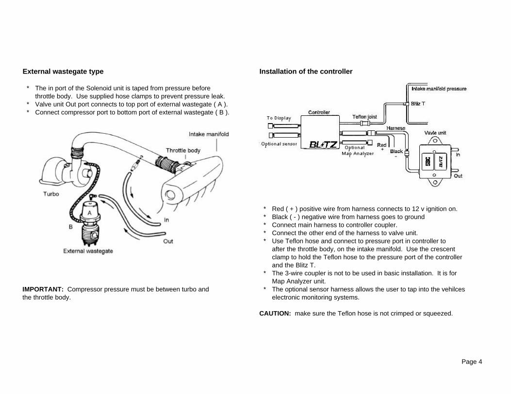
External wastegate type Installation of the controller
* The in port of the Solenoid unit is taped from pressure before throttle body. Use supplied hose clamps to prevent pressure leak.
* Valve unit Out port connects to top port of external wastegate ( A ). * Connect compressor port to bottom port of external wastegate ( B ).
* Red ( + ) positive wire from harness connects to 12 v ignition on.* Black ( - ) negative wire from harness goes to ground
* Connect main harness to controller coupler.* Connect the other end of the harness to valve unit.* Use Teflon hose and connect to pressure port in controller to
after the throttle body, on the intake manifold. Use the crescentclamp to hold the Teflon hose to the pressure port of the controllerand the Blitz T.
* The 3-wire coupler is not to be used in basic installation. It is for Map Analyzer unit.
IMPORTANT: Compressor pressure must be between turbo and * The optional sensor harness allows the user to tap into the vehilcesthe throttle body. electronic monitoring systems.
CAUTION: make sure the Teflon hose is not crimped or squeezed.
Page 4

MAIN MENUBOOST Boost Controller settings
1 To get to Main Menu, press Menu button. To set, refer to Page 62 Turn the knob to scroll for desired options. WARNING Warning and limiter settings
To set, refer to Page 7 MAIN MENU SCRAMBLE Scramble boost settings
1. Go to Main Menu and select the To set, refer to Page 7 BOOST display desired. SPEED MAP Speed Map is only used with the Blitz Power Meter I-DWARNING To set, refer to Page 8SCRAMBLE DISPLAY Different displays (up to 6)SPEED MAP Refer to Page 8DISPLAY REPLAY Record and replay REPLAY To use, please refer to Page
DATA Optional featuresRefer to Page 9
MAIN MENU AUTO PEAK Automatic Peak hold reset. 2. How to set To set, refer to Page 9
REPLAY Press enter to select. AC / WG Actuator / Wastegate settingsDATA To set, refer to Page 9AUTO PEAK OFF UNIT Boost type kg/cm2, kpa, bar and PSIAC / WG AC To set, refer to Page 9UNIT PSI CONTRAST Adjust the contrast of the display unit (0~100)CONTRAST 35 To set, refer to Page 9
BRIGHT Adjust the brightness of the display unit (0~10)To set, refer to Page 9
MAIN MENU RESET Erase and resets the boost controller 3. How to unselect To set, refer to Page 9
AUTO PEAK OFF If you press the menu button at anyAC / WG AC time, the previous screen willUNIT PSI appear.CONTRAST 35BRIGHT 15RESET
Page 5

BOOST1 In order to set desired boost MANUAL - Setting the boost pressure manually.
Press MENU button, scroll down to BOOST and WARNING - the number displayed does not represent actual boost.press enter. It is a ratio, 0 represents stock boost, 100 represents maximum
2 To select function, scroll down and press enter boost.The function will be highlighted, scroll to select or set * Always start off with a low amount ratio, then adjust to preferencedifferent setting. IMPORTANT - Boost and EGT gauges must be used when setting the
3 To unselect, press MENU button to go to previous display. SBC I-D. Always start with the boost ratio set at low then slowly adjust to desired setting.Note: Each channel can be set differently, either to AUTO or MANUAL
BOOSTSET
CHANNEL CH1 - Shows the boost ratio or boost pressure settingAUTO / MANU AUTO 1 To change boost setting press enter and scroll down to SETSET 0.6 and press enter and scroll left or right to adjust setting.GAIN 5 2 While in Boost Digital Display, the Channel and Boost setting canGRAPH SCALE 1.0 be change without going to Boost setting. Channel and Boost
setting is located under boost digital bar. By pressing enterChannel will be highlighted, scroll to Channel desired. Press enteragain to go to boost setting, set as desired.
EXPLANATION OF EACH CATEGORYGAIN
CHANNEL - Ratio of 0-100 Channel 1 ~ Channel 4 - Gain controls the boost response. The high the gain setting,
SBC I-D has 4 programmable boost settings. Each channel has its the faster the boost response will be. Stock turbo charged own individual memory and will not affect any other channels. vehicles with actuator type wastegates will usually use a gain
EXT setting of 5-15 percent. External type wastegates usuallyOnly use with the Blitz MAP Analyzer, refer to Map Analyzer requires higher gain setting.instructions WARNING - High gain setting might cause boost spikes.
OFF Note: Each channel can be set to each individual gain settingTurns boost controller off, boost pressure will be at stock.
GRAPH SCALEAUTO / MANUAL You can select the graph scale that appears on your display
AUTO - Full automatic mode screen. 1.0 ~ 1.5 ~ 2.0 ~ 2.5 kg/cm2
Dial in desire amount of boost pressure to set boost example: 1.0 ~ 1.5 ~ 2.0 ~ 2.5 x100kpaWARNING - Auto mode will not work properly on any twin 1.0 ~ 1.5 ~ 2.0 ~ 2.5 BARturbo, sequential turbo, or high boosting vehicles. 10 ~ 20 ~ 30 ~ 40 PSI
Note: Each channel can be set to different graph scale
Page 6
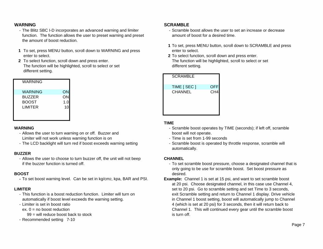
WARNING SCRAMBLE- The Blitz SBC I-D incorporates an advanced warning and limiter - Scramble boost allows the user to set an increase or decrease
function. The function allows the user to preset warning and preset amount of boost for a desired time.the amount of boost reduction.
1 To set, press MENU button, scroll down to SCRAMBLE and press 1 To set, press MENU button, scroll down to WARNING and press enter to select.
enter to select. 2 To select function, scroll down and press enter. 2 To select function, scroll down and press enter. The function will be highlighted, scroll to select or set
The function will be highlighted, scroll to select or set different setting. different setting.
SCRAMBLEWARNING
TIME [ SEC ] OFFWARNING ON CHANNEL CH4BUZZER ONBOOST 1.0LIMITER 10
TIMEWARNING - Scramble boost operates by TIME (seconds); if left off, scramble
- Allows the user to turn warning on or off. Buzzer and boost will not operate. Limiter will not work unless warning function is on - Time is set from 1-99 seconds
- The LCD backlight will turn red if boost exceeds warning setting - Scramble boost is operated by throttle response, scramble will automatically.
BUZZER- Allows the user to choose to turn buzzer off, the unit will not beep CHANNEL
if the buzzer function is turned off. - To set scramble boost pressure, choose a designated channel that isonly going to be use for scramble boost. Set boost pressure as
BOOST desired. - To set boost warning level. Can be set in kg/cm2, kpa, BAR and PSI. Example: Channel 1 is set at 15 psi, and want to set scramble boost
at 20 psi. Choose designated channel, in this case use Channel 4, LIMITER set to 20 psi. Go to scramble setting and set Time to 3 seconds,
- This function is a boost reduction function. Limiter will turn on exit Scramble setting and return to Channel 1 display. Drive vehicleautomatically if boost level exceeds the warning setting. in Channel 1 boost setting, boost will automatically jump to Channel
- Limiter is set in boost ratio 4 (which is set at 20 psi) for 3 seconds, then it will return back to ex. 0 = no boost reduction Channel 1. This will continued every gear until the scramble boost 99 = will reduce boost back to stock is turn off.
- Recommended setting 7-10 Page 7
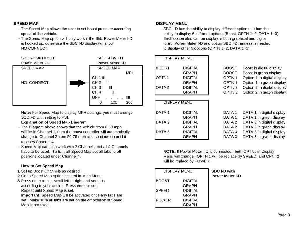
SPEED MAP DISPLAY MENU- The Speed Map allows the user to set boost pressure according - SBC I-D has the ability to display different options. It has the
speed of the vehicle. ability to display 6 different options (Boost, OPTN 1~2, DATA 1~3). - The Speed Map option will only work if the Blitz Power Meter I-D Each option also can be display is both graphical and digital
is hooked up, otherwise the SBC I-D display will show form. Power Meter I-D and option SBC I-D harness is neededNO CONNECT. to display other 5 options (OPTN 1~2, DATA 1~3).
SBC I-D WITHOUT SBC I-D WITH DISPLAY MENUPower Meter I-D Power Meter I-DSPEED MAP SPEED MAP BOOST DIGITAL BOOST Boost in digital display
MPH GRAPH BOOST Boost in graph display CH 1 III OPTN1 DIGITAL OPTN 1 Option 1 in digital display
NO CONNECT. CH 2 III GRAPH OPTN 1 Option 1 in graph display CH 3 III OPTN2 DIGITAL OPTN 2 Option 2 in digital display CH 4 IIII GRAPH OPTN 2 Option 2 in graph display OFF . . . . IIII
0 100 200 DISPLAY MENU
Note: For Speed Map to display MPH settings, you must change DATA 1 DIGITAL DATA 1 DATA 1 in digital displaySBC I-D Unit setting to PSI. GRAPH DATA 1 DATA 1 in graph displayExplanation of Speed Map Diagram DATA 2 DIGITAL DATA 2 DATA 2 in digital display
- The Diagram above shows that the vehicle from 0-50 mph GRAPH DATA 2 DATA 2 in graph display will be in Channel 1, then the boost controller will automatically DATA 3 DIGITAL DATA 3 DATA 3 in digital display
change to Channel 2 from 50-75 mph and continue on until it GRAPH DATA 3 DATA 3 in graph displayreaches Channel 4.
- Speed Map can also work with 2 Channels, not all 4 Channelshave to be used. To turn off Speed Map set all tabs to off NOTE: If Power Meter I-D is connected, both OPTNs in Display positions located under Channel 4. Menu will change. OPTN 1 will be replace by SPEED, and OPNT2
will be replace by POWER.How to Set Speed Map
1 Set up Boost Channels as desired. DISPLAY MENU SBC I-D with 2 Go to Speed Map option located in Main Menu. Power Meter I-D 3 Press enter to set, scroll left or right and set tabs BOOST DIGITAL
according to your desire. Press enter to set. GRAPHRepeat until Speed Map is set. SPEED DIGITALImportant: Speed Map will be activated once any tabs are GRAPHset. Make sure all tabs are set on the off position is Speed POWER DIGITALMap is not used. GRAPH
Page 8

DATA AC / WG - SBC I-D is capable of displaying up to 3 - AC - Actuator Type Wastegate
DATA different optional displays. Capable of - WG - External Type Wastegate displaying electronic outputs from - Refer to Page 3 and 4 for different types of wastegate
INPUT LINE 1 the ECU such as temperature, voltage, - To set, press MENU and go to Main Menu. Scroll to AC / WG,LOW [ V ] 0.0 pressure, TPS, A/F, and etc. press enter and scroll to select. Press enter to set. FIT 0.00 - Optional harness is needed to displayHIGH [ V ] 5.0 this feature. UNIT FIT 1.00 - SBC I-D has the ability to display 4 different types of boost pressureUNIT % kg/cm2 -76 cmHG ~ 2.50 kg/cm2
kpa -76 cmHG ~ 2.45x100 kpaDATA * To set up A/F, set up DATA BAR -30 inHG ~ 2.45 BAR
chart as shown below. PSI -30 inHG ~ 35.5 PSIINPUT LINE 2 - To set, press MENU and go to Main Menu. Scroll to Unit and LOW [ V ] 0.0 LOW [ V ] 0.00 press enter. Scroll left or right to select Unit, press enter to set. FIT 0.00 FIT 0.00HIGH [ V ] 12.0 HIGH [ V ] 16.0 CONTRAST FIT 200 FIT 16.0 - To set, press MENU and go to Main Menu. Scroll to CONTRAST UNIT *C UNIT VOLT and press enter. Scroll to adjust, press enter to set.
DATA BRIGHT- To set, press MENU and go to Main Menu. Scroll to BRIGHT
INPUT LINE 3 Important and press enter. Scroll to adjust, press enter to set.LOW [ V ] 0.0 - Addition instructions are included in the FIT 0.00 SBC I-D optional harness. RESETHIGH [ V ] 16.0 FIT 16UNIT Volt
AUTO PEAK
Auto Peak ON - Will automatically reset Peak Hold. Peak will reset only when throttle is release after the vehicle -> EXECUTEhas been in boost for more then 2 seconds. CANCEL
Auto Peak OFF - Peak Hold will retain the highest boost levelachieved. 1 Press MENU button, scroll down to RESET and press
- To set Auto Peak, Press MENU and go to Main Menu. Scroll to enter to select.Auto Peak, press enter and scroll to select. Press enter to set. 2 To select function, scroll down and press enter.
- To reset Peak hold, press both REC/STOP and MENU button at once. NOTE: It is recommended to reset the boost controller if the unit is not functioning properly.
Page 9
ALLRESET

DIGITAL / GRAPH DISPLAY
1 BOOST DIGITAL 2 BOOST GRAPH
1 SBC I-D has a total of 12 different displays.2 Each display can be access by either the Display option in Main
Menu or scrolling through while in Digital / Graph Display.
Display descriptionNOW Actual boost pressurePEAK Peak boost pressure
- To reset Peak: Press REC/STOP and MENU at thesame time
REC RecordWR WarningSC Scramble Boost
Shortcuts- Hold Enter for 3 seconds, this will jump you to Boost
setting menu- To change channel: Press enter, CH will be highlighted.
Scroll to desired Channel- To change boost: Press enter, 1.50 will be highlighted.
Change to desire boost setting.
Page 10

3 OPTN 1 DIGITAL 4 OPTN 1 GRAPH
* OPTN 1 is not used if Power Meter is not connected. * OPTN 1 is not used if Power Meter is not connected.
OPTN 1 in digital display OPTN 1 in graph displaywith Power Meter I-D. with Power Meter I-D.
- OPTN 1 will only work if Power Meter I-D is connected. - OPTN 1 will only work if Power Meter I-D is connected.- When Power Meter I-D is connected OPTN 1 will - When Power Meter I-D is connected OPTN 1 will
automatically change to SPEED. automatically change to SPEED.- When the Power Meter is connected, the SBC I-D - When the Power Meter is connected, the SBC I-D
can display speed. can display speed.
Page 11
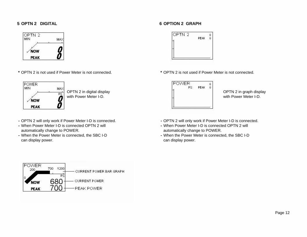
5 OPTN 2 DIGITAL 6 OPTION 2 GRAPH
* OPTN 2 is not used if Power Meter is not connected. * OPTN 2 is not used if Power Meter is not connected.
OPTN 2 in digital display OPTN 2 in graph displaywith Power Meter I-D. with Power Meter I-D.
- OPTN 2 will only work if Power Meter I-D is connected. - OPTN 2 will only work if Power Meter I-D is connected.- When Power Meter I-D is connected OPTN 2 will - When Power Meter I-D is connected OPTN 2 will
automatically change to POWER. automatically change to POWER.- When the Power Meter is connected, the SBC I-D - When the Power Meter is connected, the SBC I-D
can display power. can display power.
Page 12

7 DATA 1 ~ 3 DIGITAL 8 DATA 1 ~ 3 GRAPH
- SBC I-D is capable of displaying up to 3 - SBC I-D is capable of displaying up to 3different optional displays. Capable of different optional displays. Capable of displaying electronic outputs from displaying electronic outputs fromthe ECU such as temperature, voltage, the ECU such as temperature, voltage, pressure, TPS, A/F, and etc. pressure, TPS, A/F, and etc.
- Optional harness is needed to display - Optional harness is needed to display- Additional information will be included with - Additional information will be included with
SBC I-D optional harness. SBC I-D optional harness.
Page 13
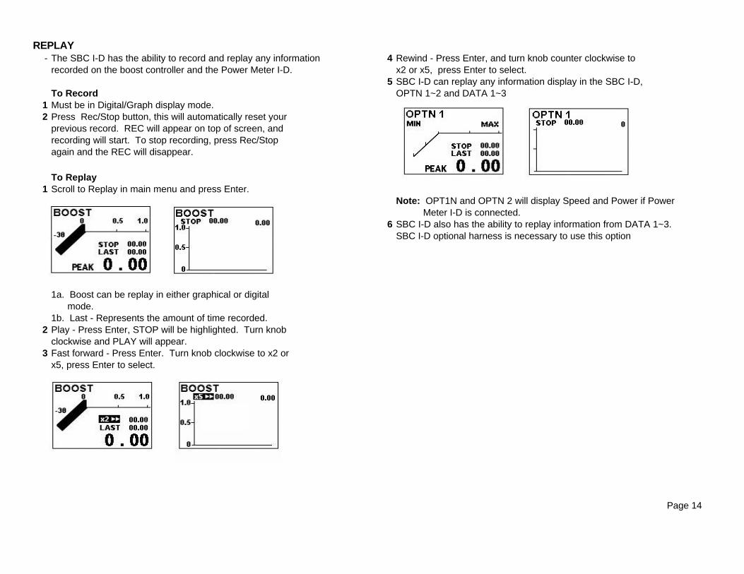
REPLAY- The SBC I-D has the ability to record and replay any information 4 Rewind - Press Enter, and turn knob counter clockwise to
recorded on the boost controller and the Power Meter I-D. x2 or x5, press Enter to select.5 SBC I-D can replay any information display in the SBC I-D,
To Record OPTN 1~2 and DATA 1~31 Must be in Digital/Graph display mode.2 Press Rec/Stop button, this will automatically reset your
previous record. REC will appear on top of screen, and recording will start. To stop recording, press Rec/Stopagain and the REC will disappear.
To Replay1 Scroll to Replay in main menu and press Enter.
Note: OPT1N and OPTN 2 will display Speed and Power if Power Meter I-D is connected.
6 SBC I-D also has the ability to replay information from DATA 1~3.SBC I-D optional harness is necessary to use this option
1a. Boost can be replay in either graphical or digital mode.1b. Last - Represents the amount of time recorded.
2 Play - Press Enter, STOP will be highlighted. Turn knob clockwise and PLAY will appear.
3 Fast forward - Press Enter. Turn knob clockwise to x2 orx5, press Enter to select.
Page 14