
INSTRUCTION MANUAL 26cc PETROL 4 in 1 MULTI-TOOL · Engine 2-stroke, Air-cooled Bore & Stroke 32 &...
36
24/11/2017 26cc PETROL 4 in 1 MULTI-TOOL Model No: THMT26 -- Product No: 1938176001 ASSEMBLY REQUIRED SAVE THESE INSTRUCTIONS SPARES & SUPPORT: 01793 333212 Please read & understand this manual, paying attention to the safety instructions, before use. The manufacturer reserves the right to change the product specification and livery according to continued product improvements. Images used are for illustration purposes only INSTRUCTION MANUAL
Transcript of INSTRUCTION MANUAL 26cc PETROL 4 in 1 MULTI-TOOL · Engine 2-stroke, Air-cooled Bore & Stroke 32 &...

24/11/2017
26cc PETROL
4 in 1 MULTI-TOOL Model No: THMT26 -- Product No: 1938176001
ASSEMBLY REQUIRED SAVE THESE INSTRUCTIONS
SPARES & SUPPORT: 01793 333212
Please read & understand this manual, paying attention to the safety instructions, before use. The manufacturer reserves the right to change the product specification and livery according to
continued product improvements. Images used are for illustration purposes only
INSTRUCTION MANUAL


CONTENTS
SPECIFICATION IMPORTANT INFORMATION GENERAL SAFETY INSTRUCTIONS GET TO KNOW YOUR MACHINE ASSEMBLY FUELING OPERATION MAINTENANCE STORAGE TROUBLE SHOOTING PARTS DIAGRAM & LIST EC DECLARATION OF CONFORMITY WARRANTY NOTES
ASSEMBLY IS REQUIRED This product requires assembly before use. See the “Assembly” section for instructions. Please check that all parts required for the assembly of this machine are included. If for any reason you believe a part for the assembly is missing or damaged, please contact us.
If you require any assistance with regards to the contents or operation of
your machine, please contact us:
TEL: 01793 333212 EMAIL: [email protected]
(MON – FRI 8.00AM TO 5.30PM EXCL. BANK HOLIDAYS)
You can register your machine at www.thehandy.co.uk

SPECIFICATION The manufacturer reserves the right to change the product specification and livery according to continued product improvements.
Model THMT26
Product Number 1938176001
Engine 2-stroke, Air-cooled
Bore & Stroke 32 & 28mm
Number of cylinder 1
Engine Displacement 25.4cm3
Rated speed 7500rpm
Maximum torque speed 6500rpm
Maximum engine speed 10500rpm
Fuel Type Unleaded Petrol
Fuel Mixture Unleaded Petrol/2-Stroke Synthetic Oil
40:1
Fuel Tank Capacity 550ml
Brushcutter Line Trimmer Pruner Hedgecutter
Cutting Diameter 254mm 400mm 19mm
Cutting Length 254mm 450mm
Chain Bar Type 3/8”
Shaft Straight Curve Straight Straight
Blades 3T
(Double Sided)
2 (Double Edged)
Spool Type Bump Feed,
Twin Line
Line Diameter 2.4mm
Chain Pitch 3/8” 0.050
Chain Links 44
File Required 5/32”
Net Weight with Power Unit (5.1kg Empty Tank)
7.0kg 6.05kg 7.1kg 7.3kg
Length with Power Unit (103mm)
185mm 170mm 212mm 228mm
Declared Sound Power Level 112 dB(A)
Vibration Front Handle: Idling 6.303 m/s2, Racing 5.323 m/s2 Rear Handle: Idling 6.128 m/s2, Racing 5.362 m/s2
Uncertainty: K=1.5 m/s2
Max Cutting Speed 6800 rpm 7000 rpm 6500 rpm 1500 rpm

IMPORTANT INFORMATION INTENDED USE The Multi-Tool is designed solely for domestic gardens, with annual use below 50 hours. This product is not intended for commercial use. Generally acknowledged accident prevention regulations and enclosed safety instructions must be observed. Only perform work described in these instructions for use, any other use is incorrect. The manufacturer will not assume responsibility for damage or injury resulting from such use.
GENERAL SAFETY INSTRUCTIONS Read and understand the owner’s manual and labels affixed to the product. Learn its application and limitations as well as the specific potential hazards. Retain these instructions for future reference. The operator is responsible for following the warnings & instructions in this manual and on the product. STAY ALERT Do not operate the machine while under the influence of drugs, alcohol, or any medication that could affect your ability to use it properly. Do not use this machine when you are tired or distracted from the job at hand. Be aware of what you are doing at all times. Use common sense. WORKING PLAN Plan your work schedule and allow plenty of time for rest. Use continuously for around 30-40 minutes per session and take between 10-20 minutes rest between work sessions. Also try to keep total amount of work performed in a single day under 2 hours or less. AVOID DANGEROUS CONDITIONS Make sure there is adequate surrounding workspace. Cluttered areas invite injuries. Keep your work area clean with sufficient light. Keep the area around the machine clear of obstructions, grease, oil, rubbish and other debris which could cause persons to fall onto moving parts. SAFE TRANSPORTATION Always carry the machine and attachments with the supplied safety guards. If transporting by vehicle, ensure is it secured horizontally, with the fuel tank at the lowest point, to prevent turnover, fuel spillage or damage. INSPECT YOUR MACHINE Check all bolts, nuts, and screws for tightness before each use, especially those securing guards and drive mechanisms. Vibration during use, may cause these to loosen. Always check to see that all other tools or equipment are removed from the working area before turning it on. Replace damaged, missing or failed parts before using it. Warning labels carry important information. Replace any missing/damaged warning labels. DRESS PROPERLY Do not wear loose clothing, gloves, scarfs, neckties or jewellery (rings, wrist watches), which can be caught in moving parts. Protective gloves and non-skid heavy-duty footwear are highly recommended when working. Wear a face or dust mask if the operation is dusty. Always wear safety glasses/goggles and/or face shields. Everyday eyeglasses have only impact resistant lenses; they are not safety glasses/goggles. Wear protective hair covering to contain long hair, preventing it from getting caught in machinery. CAUTION HOT Do not touch hot parts of the machine, burn injuries may occur. DO NOT SMOKE Do not smoke when using the machine & caution when handling fuel. We recommend you fuel the machine at least 3 metres away from where you wish to work, in case any spilt fuel ignites when starting the engine. AVOID ELECTRICAL SHOCK Do not operate near underground electrical cables, telephone lines, pipes or hoses. USE THE SHOULDER HARNESS Always use a shoulder harness. Adjust the shoulder harness to a comfortable operating position before starting. Maintain a firm grip on both handles. Keep your area clear of the machine cutting area. DO NOT OVERREACH Keep proper footing and balance at all times when using the machine. Serious injury could occur if the moving parts are unintentionally contacted. Do not store anything above or near the machine, where anyone might stand on the machine to reach them. AVOID INJURY FROM UNEXPECTED ACCIDENT Keep hands & feet out of the way of all moving parts. Do not place any part of your body or any tool e.g. in the machine during operation. Do not place any moving parts on the ground during start up.

BLOCKAGES Do not attempt to remove a blockage from a jammed machine before first switching the engine off. KICKBACK The Pruner attachment is supplied with a low KICKBACK chain, however sometimes kick back can occur, so always hold the unit firmly in two hands. The Kickback danger zone on your Pruner is the upper part of the nose of the guide bar. Never saw using this part of the guide bar, which poses a significant risk for kickback.DO NOT FORCE TOOL Always work within the rated capacity. Do not use machine for a purpose for which it was not intended. NEVER LEAVE MACHINE RUNNING UNATTENDED Do not leave the machine unattended until it has come to a complete stop. MAINTAIN YOUR MACHINE WITH CARE Clean the machine immediately after use. Keep clean to ensure it operates to its full and safest performance. When maintaining, only manufacturer original replacement parts. The use of non-original manufacturer parts may invalidate your warranty. PROTECT THE ENVIRONMENT Take left over materials & fluids to an authorised collection point or follow the stipulations in the country where the machine is used. Do not discharge into drains, soil or water. STORE IDLE EQUIPMENT When not in use, the machine should be stored in a dry location. Keep the machine away from children and others not qualified to use it.
SAFETY SYMBOLS
Safety alert symbol. Used to alert you to potential personal injury hazards. Obey all safety messages that follow this symbol to avoid possible injury.
DANGER Indicates an imminently hazardous situation which, if not avoided, will result in serious injury.
WARNING Indicates a potentially hazardous situation which, if not avoided, could result in serious injury.
CAUTION Indicates a potentially hazardous situation which, if not avoided, may result in minor or moderate injury. CAUTION Used without the safety alert symbol indicates a potentially hazardous situation which, if not avoided, may result in property damage.
1 2 3 4 5 6 7
1. Read the owner’s manual prior to operating the machine 2. Wear head, eye and ear protection 3. Wear non-skid heavy duty footwear. 4. Wear protective electrically non-conductive gloves. 5. Beware of thrown objects. 6. Warning/Attention 7. Keep all children, bystanders and animals 15 metres away from Danger Zone.
NEVER MODIFY THE MACHINE. The warranty supplied with the product is void if you make any modification to the machine or if you do not observe the proper usage guidance written in this manual.

GET TO KNOW YOUR MACHINE
Image used for illustration purposes and may differ slightly from your item.
FUEL TANK
PRIMER BULB
BRUSHCUTTER
LINE TRIMMER
GUARD
CHAIN COVER
CHAIN OIL TANK &
CAP
PETROL POWER
UNIT
CHAIN
GUARD
FUEL TANK CAP
CHOKE LEVER
THROTTLE TRIGGER
SAFETY LEVER
ON/OFF SWITCH
P-HANDLE
HARNESS HANGER
QUICK JOINT
AIR FILTER HOUSING
GUARD PRUNER
HEDGECUTTER
GUIDE BAR &
CHAIN
3T
BLADE
DOUBLE
BLADE BLADE
COVERS
SPOOL & NYLON LINE

ASSEMBLY LINE TRIMMER ATTACHMENT GUARD Place the guard onto the bent shaft of the Line Trimmer Attachment. The bracket is placed on the top of the shaft and the guard sits underneath. They are secured with two 4mm Allen Key Bolts. Tighten until secure. (Fig 1) NYLON HEAD The Nylon Head is secured to the shaft, by rotating clockwise. Do so until you reach the end of the thread (Fig 2). Secure the large nut with a suitable Spanner or Mole Grip and hand tighten until secure. (Fig 3)
BRUSHCUTTER ATTACHMENT GUARD Place the plastic guard onto the small metal guard & secure with three 5mm Allen Key bolts. (Fig 4). METAL BLADE Remove the Blade Nut, Cup & Clamp Washers. The Stepped Washer must remain (Fig 5).
Now place the blade onto the Stepped Washer, ensuring the step of the washer is placed into the hole of the blade (Fig 6). Sit the Clamp Washer onto the blade (Fig 7).
Fig 1 Fig 2 Fig 3
Fig 4
Fig 6 Fig 7
CUP WASHER
CLAMP WASHER
STEPPED WASHER
BLADE NUT
Fig 5
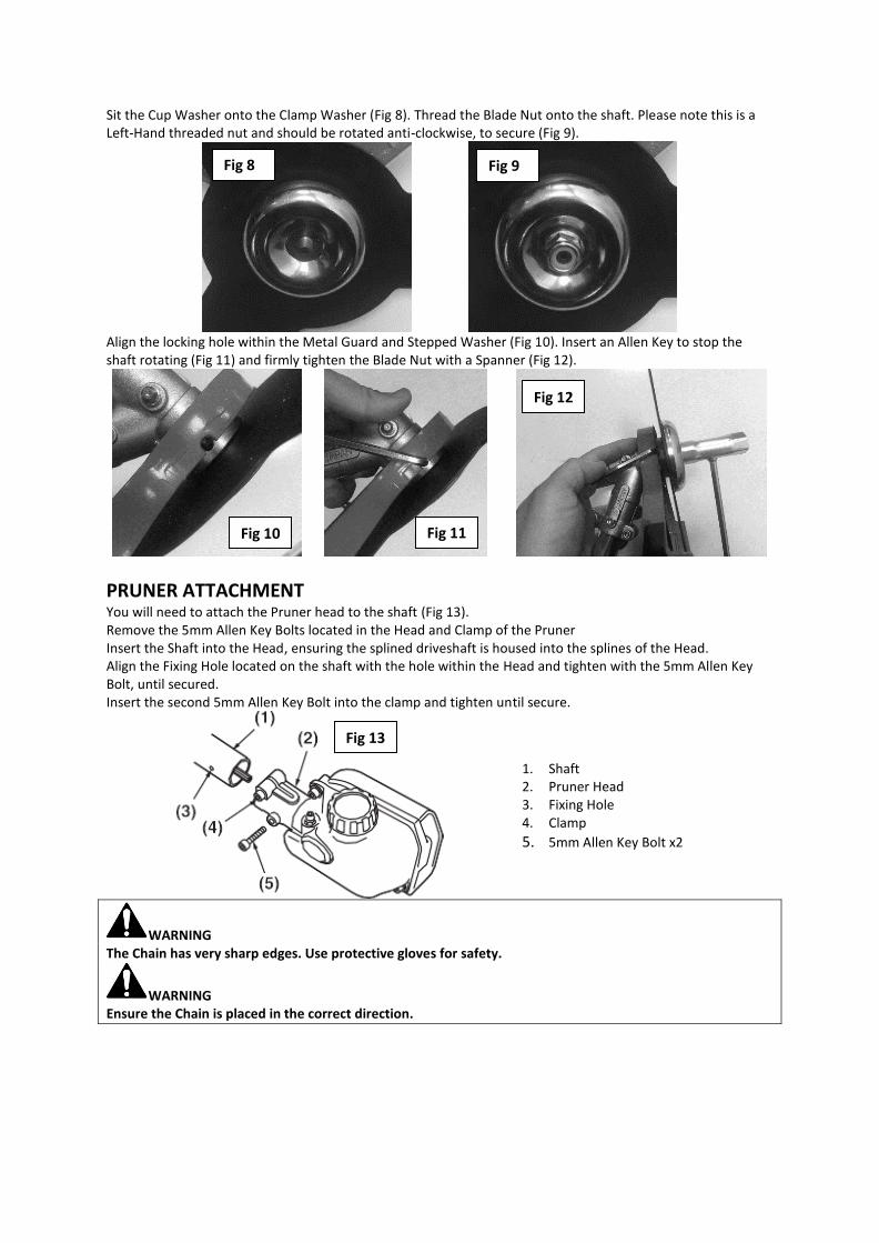
Sit the Cup Washer onto the Clamp Washer (Fig 8). Thread the Blade Nut onto the shaft. Please note this is a Left-Hand threaded nut and should be rotated anti-clockwise, to secure (Fig 9).
Align the locking hole within the Metal Guard and Stepped Washer (Fig 10). Insert an Allen Key to stop the shaft rotating (Fig 11) and firmly tighten the Blade Nut with a Spanner (Fig 12).
PRUNER ATTACHMENT You will need to attach the Pruner head to the shaft (Fig 13). Remove the 5mm Allen Key Bolts located in the Head and Clamp of the Pruner Insert the Shaft into the Head, ensuring the splined driveshaft is housed into the splines of the Head. Align the Fixing Hole located on the shaft with the hole within the Head and tighten with the 5mm Allen Key Bolt, until secured. Insert the second 5mm Allen Key Bolt into the clamp and tighten until secure.
1. Shaft 2. Pruner Head 3. Fixing Hole 4. Clamp
5. 5mm Allen Key Bolt x2
WARNING The Chain has very sharp edges. Use protective gloves for safety.
WARNING Ensure the Chain is placed in the correct direction.
Fig 8 Fig 9
Fig 10 Fig 11
Fig 12
Fig 13
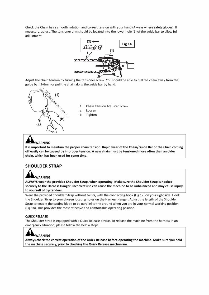
Check the Chain has a smooth rotation and correct tension with your hand (Always where safety gloves). If necessary, adjust. The tensioner arm should be located into the lower hole (1) of the guide bar to allow full adjustment.
Adjust the chain tension by turning the tensioner screw. You should be able to pull the chain away from the guide bar, 5-6mm or pull the chain along the guide bar by hand.
1. Chain Tension Adjuster Screw a. Loosen b. Tighten
WARNING It is important to maintain the proper chain tension. Rapid wear of the Chain/Guide Bar or the Chain coming off easily can be caused by improper tension. A new chain must be tensioned more often than an older chain, which has been used for some time.
SHOULDER STRAP
WARNING ALWAYS wear the provided Shoulder Strap, when operating. Make sure the Shoulder Strap is hooked securely to the Harness Hanger. Incorrect use can cause the machine to be unbalanced and may cause injury to yourself of bystanders.
Wear the provided Shoulder Strap without twists, with the connecting hook (Fig 17) on your right side. Hook the Shoulder Strap to your chosen locating holes on the Harness Hanger. Adjust the length of the Shoulder Strap to enable the cutting blade to be parallel to the ground when you are in your normal working position (Fig 18). This provides the most effective and comfortable operating position. QUICK RELEASE The Shoulder Strap is equipped with a Quick Release devise. To release the machine from the harness in an emergency situation, please follow the below steps:
WARNING Always check the correct operation of the Quick Release before operating the machine. Make sure you hold the machine securely, prior to checking the Quick Release mechanism.
Fig 14

While holding the machine securely with your left hand, pull the red tab (1) and the Shoulder Strap will release from the machine. (Fig 17)
P-HANDLE Mount the handle onto the Handle Seat (Fig 18) Insert and tighten the bolts supplied to secure the handle to the shaft in the desired position. Ensure the leg guard of the Loop Handle is on the left of the shaft and in the direction as per the arrow on the grip. (Fig 19)
QUICK JOINT The Quick Joint coupler allows you to safely attach the different attachments to the power unit. To attach your chosen attachment to the power unit, follow the below steps. 1. Loosen the Handwheel (Fig 22) 2. Align the attachment with the power unit (Fig 20) 3. Insert the attachment and depress the coupler lever. (Fig 21) 4. Ensure the attachment securing hole is aligned with the couple lever leg and secure. 5. Tighten the Handwheel until secure. (Fig 22)
Fig 15 Fig 16 Fig 17
Fig 18
Fig 19
Leg Guard
Fig 20
Fig 21 Fig 22
FUELING
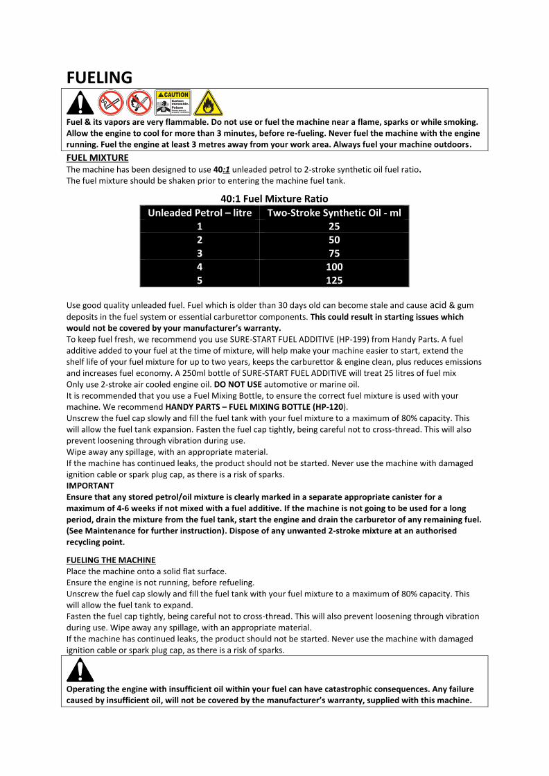
Fuel & its vapors are very flammable. Do not use or fuel the machine near a flame, sparks or while smoking. Allow the engine to cool for more than 3 minutes, before re-fueling. Never fuel the machine with the engine running. Fuel the engine at least 3 metres away from your work area. Always fuel your machine outdoors.
FUEL MIXTURE The machine has been designed to use 40:1 unleaded petrol to 2-stroke synthetic oil fuel ratio. The fuel mixture should be shaken prior to entering the machine fuel tank.
40:1 Fuel Mixture Ratio
Unleaded Petrol – litre Two-Stroke Synthetic Oil - ml 1 25 2 50 3 75 4 100 5 125
Use good quality unleaded fuel. Fuel which is older than 30 days old can become stale and cause acid & gum
deposits in the fuel system or essential carburettor components. This could result in starting issues which would not be covered by your manufacturer’s warranty. To keep fuel fresh, we recommend you use SURE-START FUEL ADDITIVE (HP-199) from Handy Parts. A fuel additive added to your fuel at the time of mixture, will help make your machine easier to start, extend the shelf life of your fuel mixture for up to two years, keeps the carburettor & engine clean, plus reduces emissions and increases fuel economy. A 250ml bottle of SURE-START FUEL ADDITIVE will treat 25 litres of fuel mix Only use 2-stroke air cooled engine oil. DO NOT USE automotive or marine oil. It is recommended that you use a Fuel Mixing Bottle, to ensure the correct fuel mixture is used with your machine. We recommend HANDY PARTS – FUEL MIXING BOTTLE (HP-120). Unscrew the fuel cap slowly and fill the fuel tank with your fuel mixture to a maximum of 80% capacity. This will allow the fuel tank expansion. Fasten the fuel cap tightly, being careful not to cross-thread. This will also prevent loosening through vibration during use. Wipe away any spillage, with an appropriate material. If the machine has continued leaks, the product should not be started. Never use the machine with damaged ignition cable or spark plug cap, as there is a risk of sparks. IMPORTANT Ensure that any stored petrol/oil mixture is clearly marked in a separate appropriate canister for a maximum of 4-6 weeks if not mixed with a fuel additive. If the machine is not going to be used for a long period, drain the mixture from the fuel tank, start the engine and drain the carburetor of any remaining fuel. (See Maintenance for further instruction). Dispose of any unwanted 2-stroke mixture at an authorised recycling point.
FUELING THE MACHINE Place the machine onto a solid flat surface. Ensure the engine is not running, before refueling. Unscrew the fuel cap slowly and fill the fuel tank with your fuel mixture to a maximum of 80% capacity. This will allow the fuel tank to expand. Fasten the fuel cap tightly, being careful not to cross-thread. This will also prevent loosening through vibration during use. Wipe away any spillage, with an appropriate material. If the machine has continued leaks, the product should not be started. Never use the machine with damaged ignition cable or spark plug cap, as there is a risk of sparks.
Operating the engine with insufficient oil within your fuel can have catastrophic consequences. Any failure caused by insufficient oil, will not be covered by the manufacturer’s warranty, supplied with this machine.

OPERATION
DANGER The DANGER ZONE on the output of the machine must be respected, to avoid serious injury. Do not allow anyone to enter the operating DANGER ZONE with you. The danger zone is an area 15 metres in radius. Insist that persons in the RISK ZONE beyond the danger zone wear eye protection from thrown objects. Do not operate if the user or bystanders have insufficient protection.
DANGER ZONE WITHIN 15 METRES – RISK ZONE GREATER THAN 15 METRES
POWER UNIT STARTING A COLD ENGINE Once you are happy that your Multi-Tool has been assembled & fueled correctly, you are now in a position to start the machine. During the first 10 hours of work, run the engine at moderate speed. Place the Power Unit onto the floor, with the fuel tank at its lowest. We recommend you use a concrete or similar surface to avoid slippage. Move the ON/OFF switch to the ‘I’ position (Fig 23). Move the Choke Lever (CL) left to the Closed position (Towards the cutting blade). Push the clear Primer Bulb (PB), 5-10 times until the fuel mixture fills the bulb. Place your left hand on the handle shaft to apply downward pressure.
Pull the Recoil Starter Handle (SH), with a smooth rapid pull for a strong spark, until the engine fires, but immediately cuts out. (We call this a false start). Apply downward pressure onto the Safety Trigger (1) and pull up the Trigger (2). This will automatically release the Choke Lever to the Open position. Release the Safety Trigger and Trigger (3) Pull the Recoil Starter again, with a smooth rapid pull. The engine should now start. Allow the engine to run for 10 seconds on normal tick over before pulling the trigger to increase the engine revs and move the cutting blade. NOTE Over choking of the engine, can cause the engine to be difficult to start due to excess fuel. When the engine fails to start after several attempts, remove the spark plug and dry it with the appropriate material.
Choke Closed Cold Start Position
Choke Open Warm Start or Run Position
Fig 23
STARTING A WARM ENGINE Place the Power Unit onto the floor, with the fuel tank at its lowest. We recommend you use a concrete or similar surface to avoid slippage. Move the ON/OFF switch to the ‘I’ position. Ensure the Choke Lever is to the right in the Open position. Pull the Recoil Starter again, with a smooth rapid pull. The engine should now start, and you are free to operate the machine.
WARNING The product is equipped with a centrifugal clutch mechanism, so the cutting blade should not move on start up or tick over. If the cutting blade does move, stop the engine immediately and refer to the Trouble Shooting section of this manual.
STOPPING THE ENGINE
• Release the throttle trigger and allow the engine to idle for a few moments.
• Move the ON/OFF switch to the ‘O’ position.
WARNING Attachments may continue to rotate for a few seconds after the engine has stopped.
GENERAL USE
WARNING Prior to using the Multi-Tool, ensure all nuts, bolts & screws are securely tightened. Always have a firm footing and use two hands. Always position the Power Unit on your right side, with all attachments. Using it on the left side will expose the user to the exhaust. Hot surfaces can result in burns. The trigger handle should be positioned at waist height. Operate the trigger with your right hand & hold the P-handle with your left hand. The trigger increases and decreases the power of the engine to the attachment, increasing the revolution/reciprocation of the attachment.
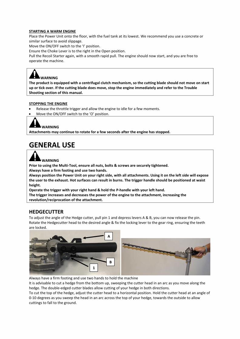
HEDGECUTTER To adjust the angle of the Hedge cutter, pull pin 1 and depress levers A & B, you can now release the pin. Rotate the Hedgecutter head to the desired angle & fix the locking lever to the gear ring, ensuring the teeth are locked.
Always have a firm footing and use two hands to hold the machine It is advisable to cut a hedge from the bottom up, sweeping the cutter head in an arc as you move along the hedge. The double-edged cutter blades allow cutting of your hedge in both directions. To cut the top of the hedge, adjust the cutter head to a horizontal position. Hold the cutter head at an angle of 0-10 degrees as you sweep the head in an arc across the top of your hedge, towards the outside to allow cuttings to fall to the ground.
1
B
A

Pay special attention to hedges which are positioned along wire fencing. If the cutting blades contact the fence, damage may occur. If the blade meets a stone, wire or other foreign object, stop immediately and check for any damage to the blades immediately. Do not attempt to remove any twigs or branches jammed in the blades, without first turning the engine off. Always check for any damage before each use and replace damaged blades immediately, with an approved replacement part. Always fit the supplied blade guard when the Hedgecutter is not in use.
BRUSHCUTTER
WARNING Always wear safety goggles or glasses to protect your eyes. Never lean over the rotating head. Stones or other debris could be thrown towards your face and cause serious personal injury. Always keep the guard in place.
Operate with the power unit on your right side, using the Shoulder Strap. Always keep a firm grip with both hands during operation. The machine should be held at a comfortable position, with the trigger handle at hip height. Adjust the shoulder strap to suit. Maintain a firm footing in case the machine hits a solid object & kicks back. Do not use the Brushcutter near fencing, posts, buildings or other immoveable objects. If a hard object is struck, immediately stop the machine and inspect for damage. Use the front left side of the cutting rotation. Guide the blade from left to right, with the blade tilted slightly towards the left. Be sure that the blade and holder are positioned and secured correctly. If assembled incorrectly, excessive vibration made be felt and the machine must be stopped immediately, and the correct assembly instructions followed.
Do not attempt to cut foliage which is too long. We recommended you cut long foliage in stages. The blade may become seized by foliage if the engine speed is too low or you attempt to cut too deep into the growth. Adjust the engine speed and cut in stages to avoid stoppages.
WARNING DO NOT contact the metal blade with utility wires, metal stakes, rubber, masonry, rocks, fences, and trees.
DANGER Rocks & metal can dull or damage a blade. Wires can wrap around the blade head or be thrown in the air. DO NOT cut with a dull, cracked or damaged metal blade. Before cutting, inspect for obstructions. If an obstruction cannot be removed, mark its location clearly so you can avoid it during operation.
SCYTHING WEEDS This is cutting by swinging the blade in a level arc. It can quickly clear areas of field grass and weeds. Scything should not be used to cut large, tough weeds or woody growths. Scything can be done in both directions, or just in one way which results in the debris being thrown away from you. This is done by using the side of the blade that it is rotating away from you. Tilt the blade downwards slightly, on this same side. You will be hit by some debris if you scythe in both directions
LINE TRIMMER
WARNING Always wear safety goggles or glasses to protect your eyes. Never lean over the rotating head. Stones or other debris could be thrown towards your face and cause serious personal injury. Always ensure the guard is in place.
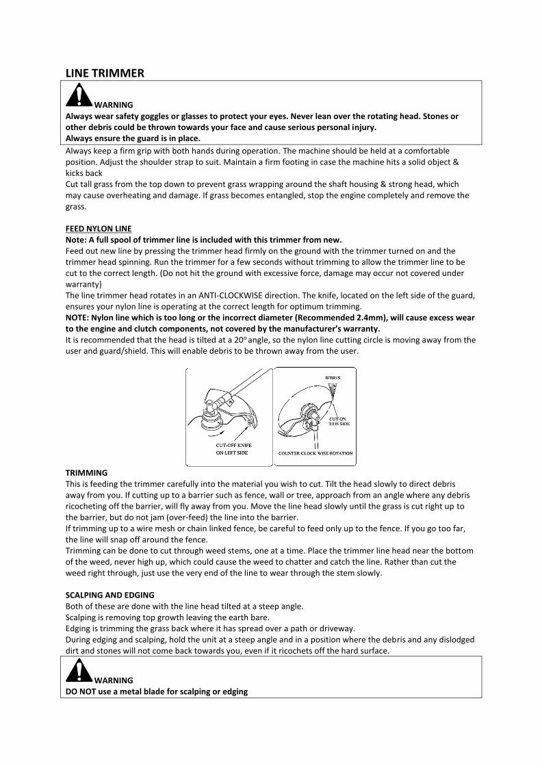
Always keep a firm grip with both hands during operation. The machine should be held at a comfortable position. Adjust the shoulder strap to suit. Maintain a firm footing in case the machine hits a solid object & kicks back Cut tall grass from the top down to prevent grass wrapping around the shaft housing & strong head, which may cause overheating and damage. If grass becomes entangled, stop the engine completely and remove the grass. FEED NYLON LINE Note: A full spool of trimmer line is included with this trimmer from new. Feed out new line by pressing the trimmer head firmly on the ground with the trimmer turned on and the trimmer head spinning. Run the trimmer for a few seconds without trimming to allow the trimmer line to be cut to the correct length. (Do not hit the ground with excessive force, damage may occur not covered under warranty) The line trimmer head rotates in an ANTI-CLOCKWISE direction. The knife, located on the left side of the guard, ensures your nylon line is operating at the correct length for optimum trimming. NOTE: Nylon line which is too long or the incorrect diameter (Recommended 2.4mm), will cause excess wear to the engine and clutch components, not covered by the manufacturer’s warranty. It is recommended that the head is tilted at a 20o angle, so the nylon line cutting circle is moving away from the user and guard/shield. This will enable debris to be thrown away from the user.
TRIMMING This is feeding the trimmer carefully into the material you wish to cut. Tilt the head slowly to direct debris away from you. If cutting up to a barrier such as fence, wall or tree, approach from an angle where any debris ricocheting off the barrier, will fly away from you. Move the line head slowly until the grass is cut right up to the barrier, but do not jam (over-feed) the line into the barrier. If trimming up to a wire mesh or chain linked fence, be careful to feed only up to the fence. If you go too far, the line will snap off around the fence. Trimming can be done to cut through weed stems, one at a time. Place the trimmer line head near the bottom of the weed, never high up, which could cause the weed to chatter and catch the line. Rather than cut the weed right through, just use the very end of the line to wear through the stem slowly. SCALPING AND EDGING Both of these are done with the line head tilted at a steep angle. Scalping is removing top growth leaving the earth bare. Edging is trimming the grass back where it has spread over a path or driveway. During edging and scalping, hold the unit at a steep angle and in a position where the debris and any dislodged dirt and stones will not come back towards you, even if it ricochets off the hard surface.
WARNING DO NOT use a metal blade for scalping or edging
PRUNER
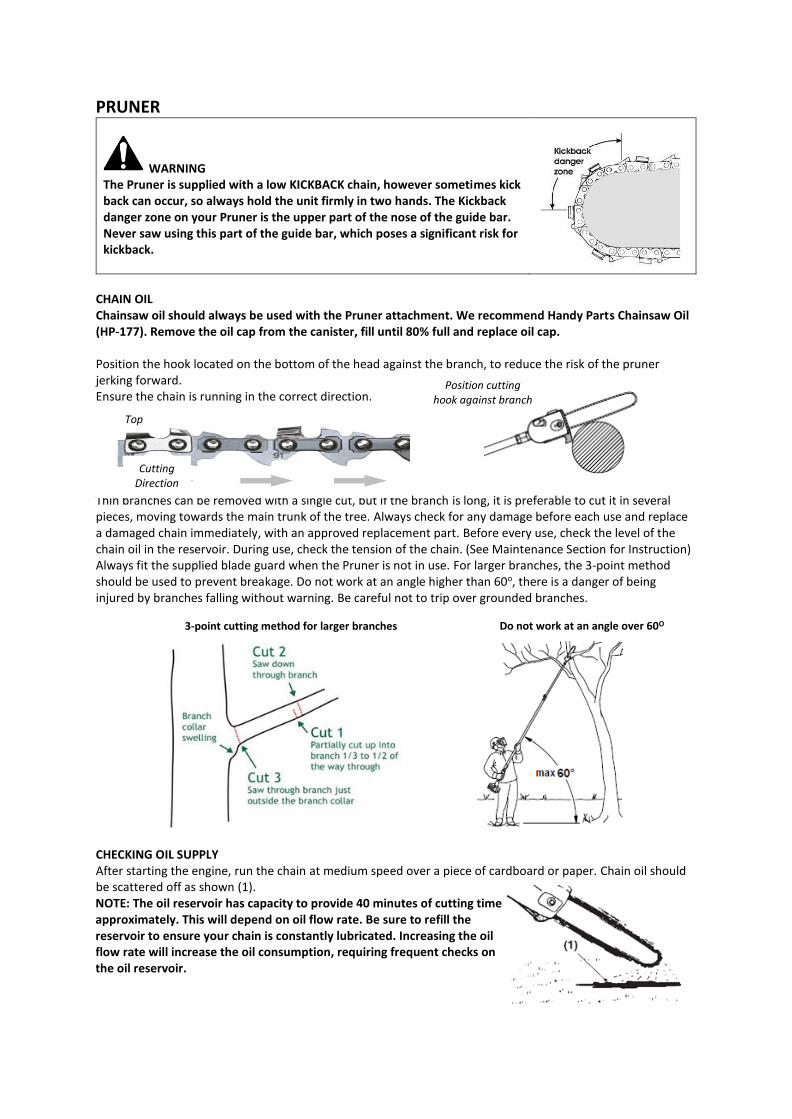
WARNING The Pruner is supplied with a low KICKBACK chain, however sometimes kick back can occur, so always hold the unit firmly in two hands. The Kickback danger zone on your Pruner is the upper part of the nose of the guide bar. Never saw using this part of the guide bar, which poses a significant risk for kickback.
CHAIN OIL Chainsaw oil should always be used with the Pruner attachment. We recommend Handy Parts Chainsaw Oil (HP-177). Remove the oil cap from the canister, fill until 80% full and replace oil cap. Position the hook located on the bottom of the head against the branch, to reduce the risk of the pruner jerking forward. Ensure the chain is running in the correct direction.
Thin branches can be removed with a single cut, but if the branch is long, it is preferable to cut it in several pieces, moving towards the main trunk of the tree. Always check for any damage before each use and replace a damaged chain immediately, with an approved replacement part. Before every use, check the level of the chain oil in the reservoir. During use, check the tension of the chain. (See Maintenance Section for Instruction) Always fit the supplied blade guard when the Pruner is not in use. For larger branches, the 3-point method should be used to prevent breakage. Do not work at an angle higher than 60o, there is a danger of being injured by branches falling without warning. Be careful not to trip over grounded branches.
CHECKING OIL SUPPLY After starting the engine, run the chain at medium speed over a piece of cardboard or paper. Chain oil should be scattered off as shown (1). NOTE: The oil reservoir has capacity to provide 40 minutes of cutting time approximately. This will depend on oil flow rate. Be sure to refill the reservoir to ensure your chain is constantly lubricated. Increasing the oil flow rate will increase the oil consumption, requiring frequent checks on the oil reservoir.
Cutting Direction
Top
3-point cutting method for larger branches Do not work at an angle over 60O
Position cutting hook against branch
ADJUSTING THE OIL FLOW RATE
WARNING Never fill the oil reservoir or adjust the oiler with the engine running.
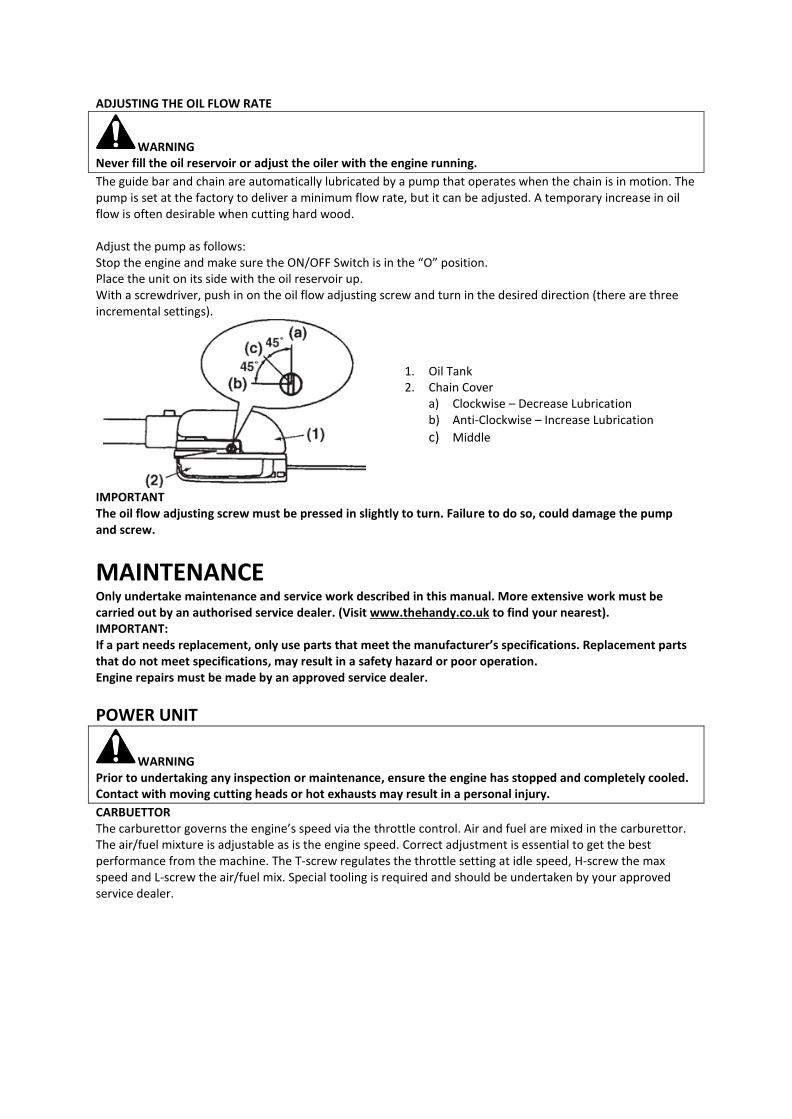
The guide bar and chain are automatically lubricated by a pump that operates when the chain is in motion. The pump is set at the factory to deliver a minimum flow rate, but it can be adjusted. A temporary increase in oil flow is often desirable when cutting hard wood. Adjust the pump as follows: Stop the engine and make sure the ON/OFF Switch is in the “O” position. Place the unit on its side with the oil reservoir up. With a screwdriver, push in on the oil flow adjusting screw and turn in the desired direction (there are three incremental settings).
1. Oil Tank 2. Chain Cover
a) Clockwise – Decrease Lubrication b) Anti-Clockwise – Increase Lubrication
c) Middle
IMPORTANT The oil flow adjusting screw must be pressed in slightly to turn. Failure to do so, could damage the pump and screw.
MAINTENANCE Only undertake maintenance and service work described in this manual. More extensive work must be carried out by an authorised service dealer. (Visit www.thehandy.co.uk to find your nearest). IMPORTANT: If a part needs replacement, only use parts that meet the manufacturer’s specifications. Replacement parts that do not meet specifications, may result in a safety hazard or poor operation. Engine repairs must be made by an approved service dealer.
POWER UNIT
WARNING Prior to undertaking any inspection or maintenance, ensure the engine has stopped and completely cooled. Contact with moving cutting heads or hot exhausts may result in a personal injury.
CARBUETTOR The carburettor governs the engine’s speed via the throttle control. Air and fuel are mixed in the carburettor. The air/fuel mixture is adjustable as is the engine speed. Correct adjustment is essential to get the best performance from the machine. The T-screw regulates the throttle setting at idle speed, H-screw the max speed and L-screw the air/fuel mix. Special tooling is required and should be undertaken by your approved service dealer.
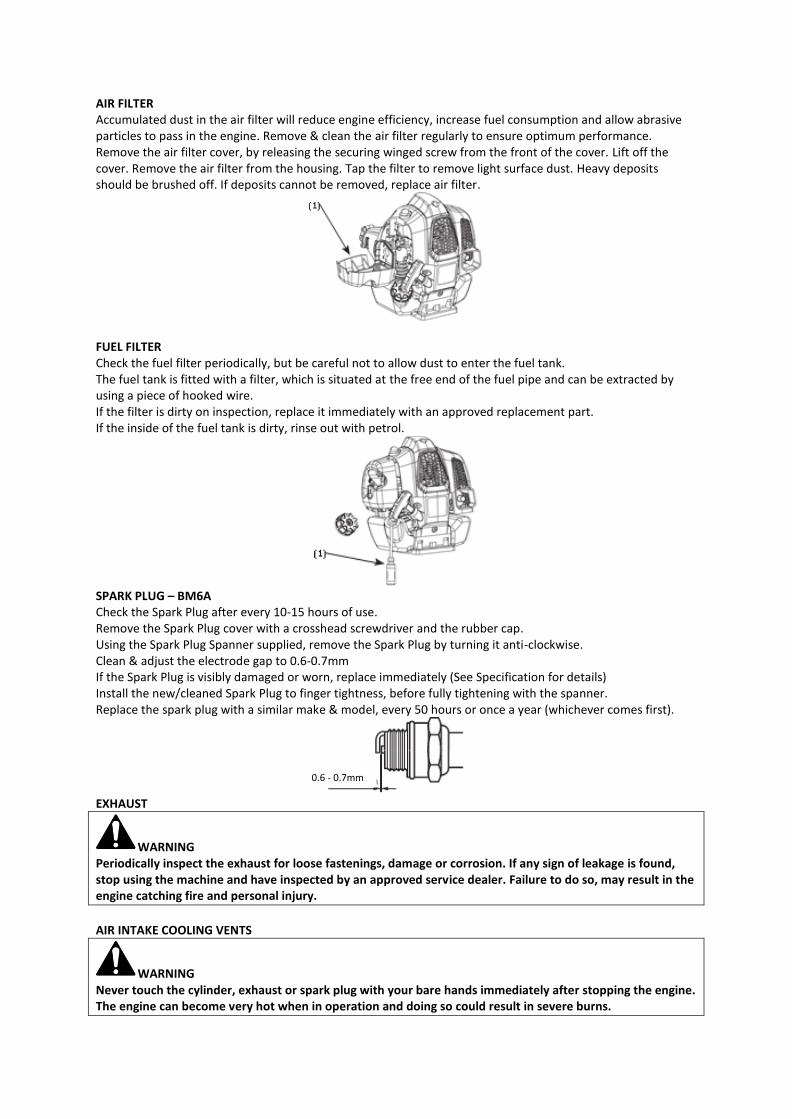
AIR FILTER Accumulated dust in the air filter will reduce engine efficiency, increase fuel consumption and allow abrasive particles to pass in the engine. Remove & clean the air filter regularly to ensure optimum performance. Remove the air filter cover, by releasing the securing winged screw from the front of the cover. Lift off the cover. Remove the air filter from the housing. Tap the filter to remove light surface dust. Heavy deposits should be brushed off. If deposits cannot be removed, replace air filter.
FUEL FILTER Check the fuel filter periodically, but be careful not to allow dust to enter the fuel tank. The fuel tank is fitted with a filter, which is situated at the free end of the fuel pipe and can be extracted by using a piece of hooked wire. If the filter is dirty on inspection, replace it immediately with an approved replacement part. If the inside of the fuel tank is dirty, rinse out with petrol.
SPARK PLUG – BM6A Check the Spark Plug after every 10-15 hours of use. Remove the Spark Plug cover with a crosshead screwdriver and the rubber cap. Using the Spark Plug Spanner supplied, remove the Spark Plug by turning it anti-clockwise. Clean & adjust the electrode gap to 0.6-0.7mm If the Spark Plug is visibly damaged or worn, replace immediately (See Specification for details) Install the new/cleaned Spark Plug to finger tightness, before fully tightening with the spanner. Replace the spark plug with a similar make & model, every 50 hours or once a year (whichever comes first).
EXHAUST
WARNING Periodically inspect the exhaust for loose fastenings, damage or corrosion. If any sign of leakage is found, stop using the machine and have inspected by an approved service dealer. Failure to do so, may result in the engine catching fire and personal injury.
AIR INTAKE COOLING VENTS
WARNING Never touch the cylinder, exhaust or spark plug with your bare hands immediately after stopping the engine. The engine can become very hot when in operation and doing so could result in severe burns.
0.6 - 0.7mm
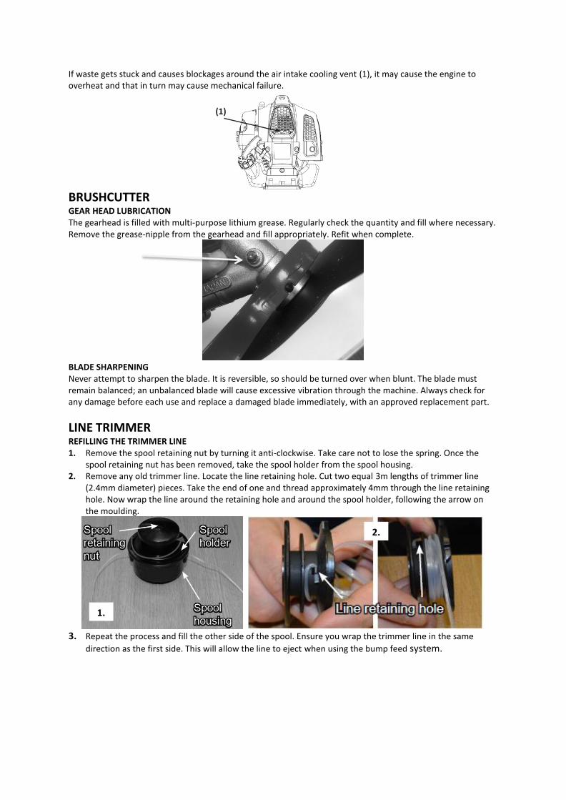
If waste gets stuck and causes blockages around the air intake cooling vent (1), it may cause the engine to overheat and that in turn may cause mechanical failure.
BRUSHCUTTER GEAR HEAD LUBRICATION The gearhead is filled with multi-purpose lithium grease. Regularly check the quantity and fill where necessary. Remove the grease-nipple from the gearhead and fill appropriately. Refit when complete.
BLADE SHARPENING Never attempt to sharpen the blade. It is reversible, so should be turned over when blunt. The blade must remain balanced; an unbalanced blade will cause excessive vibration through the machine. Always check for any damage before each use and replace a damaged blade immediately, with an approved replacement part.
LINE TRIMMER REFILLING THE TRIMMER LINE 1. Remove the spool retaining nut by turning it anti-clockwise. Take care not to lose the spring. Once the
spool retaining nut has been removed, take the spool holder from the spool housing. 2. Remove any old trimmer line. Locate the line retaining hole. Cut two equal 3m lengths of trimmer line
(2.4mm diameter) pieces. Take the end of one and thread approximately 4mm through the line retaining hole. Now wrap the line around the retaining hole and around the spool holder, following the arrow on the moulding.
3. Repeat the process and fill the other side of the spool. Ensure you wrap the trimmer line in the same
direction as the first side. This will allow the line to eject when using the bump feed system.
1.
2.
(1)
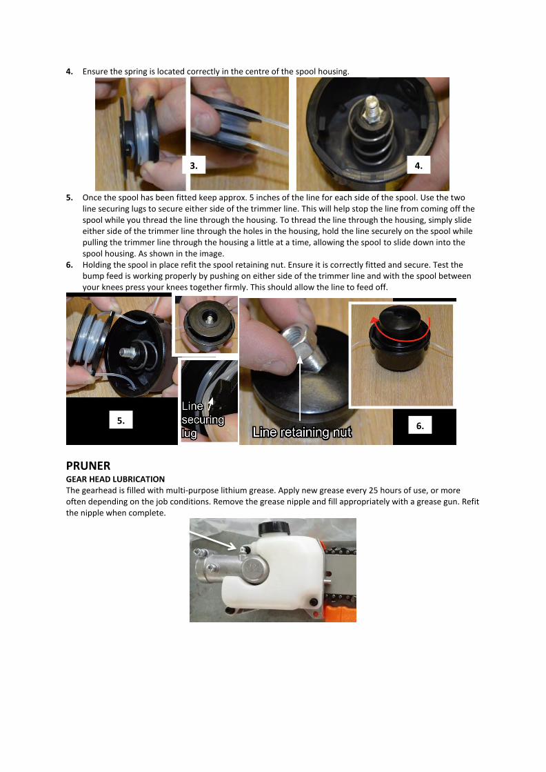
4. Ensure the spring is located correctly in the centre of the spool housing.
5. Once the spool has been fitted keep approx. 5 inches of the line for each side of the spool. Use the two
line securing lugs to secure either side of the trimmer line. This will help stop the line from coming off the spool while you thread the line through the housing. To thread the line through the housing, simply slide either side of the trimmer line through the holes in the housing, hold the line securely on the spool while pulling the trimmer line through the housing a little at a time, allowing the spool to slide down into the spool housing. As shown in the image.
6. Holding the spool in place refit the spool retaining nut. Ensure it is correctly fitted and secure. Test the bump feed is working properly by pushing on either side of the trimmer line and with the spool between your knees press your knees together firmly. This should allow the line to feed off.
PRUNER GEAR HEAD LUBRICATION The gearhead is filled with multi-purpose lithium grease. Apply new grease every 25 hours of use, or more often depending on the job conditions. Remove the grease nipple and fill appropriately with a grease gun. Refit the nipple when complete.
3. 4.
5. 6.
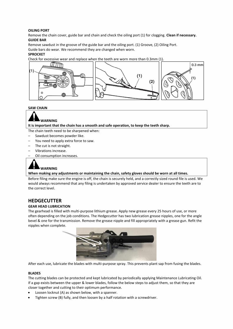
OILING PORT Remove the chain cover, guide bar and chain and check the oiling port (1) for clogging. Clean if necessary. GUIDE BAR Remove sawdust in the groove of the guide bar and the oiling port. (1) Groove, (2) Oiling Port. Guide bars do wear. We recommend they are changed when worn. SPROCKET Check for excessive wear and replace when the teeth are worn more than 0.3mm (1).
SAW CHAIN
WARNING It is important that the chain has a smooth and safe operation, to keep the teeth sharp.
The chain teeth need to be sharpened when:
– Sawdust becomes powder like.
– You need to apply extra force to saw.
– The cut is not straight.
– Vibrations increase.
– Oil consumption increases.
WARNING When making any adjustments or maintaining the chain, safety gloves should be worn at all times.
Before filing make sure the engine is off, the chain is securely held, and a correctly sized round file is used. We would always recommend that any filing is undertaken by approved service dealer to ensure the teeth are to the correct level.
HEDGECUTTER GEAR HEAD LUBRICATION The gearhead is filled with multi-purpose lithium grease. Apply new grease every 25 hours of use, or more often depending on the job conditions. The Hedgecutter has two lubrication grease nipples, one for the angle bevel & one for the transmission. Remove the grease nipple and fill appropriately with a grease gun. Refit the nipples when complete.
After each use, lubricate the blades with multi-purpose spray. This prevents plant sap from fusing the blades. BLADES The cutting blades can be protected and kept lubricated by periodically applying Maintenance Lubricating Oil. If a gap exists between the upper & lower blades, follow the below steps to adjust them, so that they are closer together and cutting to their optimum performance.
• Loosen locknut (A) as shown below, with a spanner.
• Tighten screw (B) fully, and then loosen by a half rotation with a screwdriver.

• While holding the screw in position with a screwdriver, tighten the locknut with a spanner.
• Check to make sure, flat washer (C) is loose enough to be turned by your finger. Tightening the screw too tightly may make it impossible for the blades to move. Conversely, not tightening the screw sufficiently may make the blades feel dull and cause leaves and branches to become caught in the blades.
System Component Procedure Before
Use
Every 25hrs after
Every 50hrs after
Every 100hrs after
Note
ENGINE
Fuel leaks & spillage Wipe clean ✔
Fuel tank, air filter, fuel filter Inspect or Clean ✔ ✔ Replace if necessary
Idle Adjusting Screw See Operation section ✔ Replace carburettor
if necessary
Spark Plug Clean and readjust gap ✔ GAP 0.6-0.7mm.
Replace if necessary
Cylinder fins, air intake fan Clean ✔
Exhaust Check operation ✔
SHAFT
Throttle trigger, On/Off switch
Check operation ✔
Cutting parts Replace if faulty ✔
Nuts, bolts or screws Tighten or replace ✔ ✔ Not adjusting screws
Transmission Grease ✔
Cutting guard Ensure attached ✔
CUTTING UNIT
Oiling port Clean ✔
Guide bar Clean ✔
Sprocket Inspect or replace ✔ ✔
Saw chain Inspect or sharpen ✔
STORAGE For years of trouble free service, make sure the machine is clean and dry before storing. Before storing, clean the machine thoroughly as indicated above. Store indoors or in a safe, locked protected area during severe weather and winter months. DO NOT STORE in an enclosed area, where fuel vapors can reach an open hot flame. DO NOT STORE fuel in the machine. Ensure fuel is removed from the fuel tank and carburetor. If storing for an extended period, inspect, clean and repair the machine if necessary. Remove all fuel from the fuel tank. Start the engine, this will remove all fuel from the carburetor and fuel lines. Remove the spark plug, pour a small quantity of 2-stroke oil into the spark plug hole of the cylinder and re-seat spark plug. Store in a clean, dry, dust free area. DO NOT STORE fuel for longer than 30 days. Fuel can become stale and cause damage to the engine carburettor, which is not covered by the machines manufacturer’s warranty.

TROUBLE SHOOTING Failures such as a difficulty in starting the engine, irregularity in functions and abnormality in performance can normally be prevented if careful attention is paid to all operating instructions & maintenance procedures. FAILURE TO START Correctly follow the starting procedure, not setting the choke or priming the engine can cause it not to start. Ensure that fuel is fresh and clean. Dispose of fuel from the tank, particularly if over 30 days old. Install a new, properly gapped spark plug. When there is serious trouble with the unit, have your approved service dealer inspect it for you. POWER UNIT POSSIBLE CAUSE SOLUTION
Non-Start, Power Loss or Sudden Stop
1. Fuel Tank Empty 2. Mixture not reaching carburettor 3. Water in fuel mixture 4. The Air Filter is dirty 5. Carbon deposits in cylinder or
exhaust.
1. Add Fuel 2. Drain mixture from fuel system 3. Clean Fuel Filter 4. Clean Air Filter 5. Clean all affected parts or change
exhaust.
Engine runs, head not rotating
Possible clutch failure Take to authorised service dealer
Power Unit is smoking Incorrect fuel/oil mixture Drain tank & use 40-parts unleaded fuel to 1-part synthetic oil (40:1).
Idle is lumpy or attachment rotating without trigger depressed
Idle Screw is incorrectly adjusted Take to authorised service dealer
LINE TRIMMER POSSIBLE CAUSE SOLUTION
Line will not advance
1. Line is welded to itself 2. Insufficient line on spool 3. Line has worn too short 4. Line is tangled in spool
1. Lubricate with silicone spray 2. Add more line 3. Bump head on ground to feed line. 4. Remove line from the spool & rewind
Trimmer head not rotating Buildup of grass or grass wrapped around head
Clean head by removing grass
Grass wrapping around attachment shaft & head assembly
Cutting tall grass at ground level Cut tall grass in stages.
PRUNER POSSIBLE CAUSE SOLUTION
Difficult to cut branches Chain is blunt Replace chain or arrange for sharpening
Chain is smoking Lack of lubrication 1. Check that oil duct is clear 2. Top up the oil reservoir with chain oil
Chain not rotating 1. Chain too tight 2. Chain Sprocket faulty
1. Adjust chain tension 2. Replace
HEDGECUTTER POSSIBLE CAUSE SOLUTION
Blades not reciprocating 1. Blades fused by sap 2. Gear head issue
1. Lubricate with Multi-purpose spray and leave to soak
2. Take to authorised service dealer
BRUSHCUTTER POSSIBLE CAUSE SOLUTION
Vibration through machine Blade has been incorrectly assembled Strip down blade assembly, rebuild.

PARTS DIAGRAM & LIST POWER UNIT
Item No Part No Description Qty Item No Part No Description Qty
B1 TH243-PUB1 Coupler Assembly 1 B14 TH243-PUB14 Bearing 6000 1
B2 TH243-PUB2 Washer 6x12x1.5 1 B15 TH243-PUB15 Shaft Joint 1
B3 TH243-PUB3 Handwheel 1 B16 TH243-PUB16 Snap Ring 26 1
B4 TH243-PUB4 Coupler Body 1 B17 Nut M5 1
B5 TH243-PUB5 Bolt M4x16 1 B18 Lower P Handle 1
B6 TH243-PUB6 Bolt M6x30 1 B20 Upper P Handle 1
B7 TH243-PUB7 Bolt M5x12 2 B21 Bolts M5x35 4
B8 TH243-PUB8 Lever 1 B19 TH243-PUB19 Handle Seat 1
B9 TH243-PUB9 Lever Spring 1 B22 TH243-PUB22 Trigger Assembly 1
B10 TH243-PUB10 M6 Nut 2 B23 TH243-PUB23 Harness Hanger 1
B11 TH243-PUB11 M6 Acorn Nut 1 B24 Inner Driveshaft 1
B12 TH243-PUB12 M4 Nut 1 B25 Shaft Bearing 3
B13 TH243-PUB13 Snap Ring 10 1 B26 Outer Shaft 1
B27 TH243-PUB27 Complete G3404 Engine 1
TH243-PUB17
TH243-PUB24
NOTE: Parts Lists are supplied for information purposes only, not all parts are stocked individually & we recommend you contact our Spares Team on 01793 333212 for expert advice.

ENGINE
NOTE: Parts Lists are supplied for information purposes only, not all parts are stocked individually & we recommend
you contact our Spares Team on 01793 333212 for expert advice.

Item N
oPar
t No
Descr
iption
QtyIte
m No
Part N
oDe
script
ionQty
Item N
oPar
t No
Descr
iption
QtyIte
m No
Part N
oDe
script
ionQty
A1TH
238-EN
GA1
Left C
lamp
1A2
3TH
238-EN
GA23
Ignitio
n Coil
1A4
4TH
238-EN
GA44
Thrott
le Line
Set
1A6
8TH
238-EN
GA68
Cylind
er1
A2TH
238-EN
GA2
Right
Clamp
1A2
4TH
238-EN
GA24
Oil Se
al 12x2
2x72
A45
TH238
-ENGA
45Bo
lt M4x1
02
A69
TH238
-ENGA
69Spa
rk Plug
BM6A
1
A3TH
238-EN
GA3
Bolt M
5x25
2A2
5TH
238-EN
GA25
Bolt M
5x20
4A4
6TH
238-EN
GA46
Air Fil
ter Bu
tterfly
Bolt
1A7
0TH
238-EN
GA70
Exhaus
t Gask
et1
A4TH
238-EN
GA4
Bolt M
5x12
1A2
6TH
238-EN
GA26
Right
Crankc
ase1
A47
TH238
-ENGA
47Air
Filter
Cover
1A7
1TH
238-EN
GA71
Exhaus
t1
A5TH
238-EN
GA5
Anti-V
ibrati
on Se
t1
A27
TH238
-ENGA
27Be
aring
6001 (1
2x28x8
)2
A48
TH238
-ENGA
48Bo
lt M5x4
52
A72
TH238
-ENGA
72Bo
lt M5x5
51
A6TH
238-EN
GA6
Clutch
Housi
ng1
A28
TH238
-ENGA
28Ke
y 3x3.
7x10
1A4
9TH
238-EN
GA49
Air Fil
ter Pla
te1
A73
TH238
-ENGA
73Exh
aust H
eat Co
ver1
A7TH
238-EN
GA7
Circlip
151
A29
TH238
-ENGA
29Cra
nkshaf
t1
A50
TH238
-ENGA
50Air
Filter
1A7
5TH
238-EN
GA75
Cylind
er Ga
sket
1
A8TH
238-EN
GA8
Beari
ng 620
21
A30
TH238
-ENGA
30Pin
5x10
2A5
1TH
238-EN
GA51
Air Fil
ter Ho
using
1A7
6TH
238-EN
GA76
Piston
Ring
2
A9TH
238-EN
GA9
Beari
ng Pla
te1
A31
TH238
-ENGA
31Cra
nkcase
Gaske
t1
A52
TH238
-ENGA
52Car
buret
tor1
A77
TH238
-ENGA
77Pis
ton1
A10
TH238
-ENGA
10Scr
ew ST
4.8x14
4A3
2TH
238-EN
GA32
Left C
rankca
se1
A53
TH238
-ENGA
53Car
buret
tor Ga
sket
1A7
8TH
238-EN
GA78
Piston
Pin1
A11
TH238
-ENGA
11Pas
sive P
late
1A3
3TH
238-EN
GA33
Starte
r Paw
l1
A54
TH238
-ENGA
54Bo
lt M4x2
01
A79
TH238
-ENGA
79Pis
ton Pin
Snap
Ring
2
A12
TH238
-ENGA
12Ho
using
Scree
n1
A100
Recoi
l Asse
mbly
1A5
5TH
238-EN
GA55
Insula
tor1
A80
TH238
-ENGA
80Ne
edle B
earing
8x11x
91
A13
TH238
-ENGA
13Scr
ew ST
4x14
4A3
4Re
coil H
andle B
ung
1A5
6TH
238-EN
GA56
Insula
tor Ga
sket
1A8
1TH
238-EN
GA81
Washe
r1
A14
TH238
-ENGA
14Bo
lt M5x1
66
A35
Recoi
l Hand
le1
A101
TH238
-ENGA
101Fue
l Tank
Assem
bly1
A82
TH238
-ENGA
82Pri
mer B
ulb1
A15
TH238
-ENGA
15Clu
tch Bo
lt2
A36
Recoi
l Rope
1A5
7TH
238-EN
GA57
Retur
n Pipe
2.5x5x
1701
A83
TH238
-ENGA
83Mo
tor Ho
using
1
A16
TH238
-ENGA
16Clu
tch Bo
lt Wash
er 8x1
3x.05
2A3
7Squ
are Nu
t2
A58
TH238
-ENGA
58Fue
l Pipe
Bung
1A8
4TH
238-EN
GA84
Prime
r Pipe
2.5x5x
651
A17
TH238
-ENGA
17Clu
tch Sh
oe1
A38
Crossh
ead Sc
rew M5
x101
A59
TH238
-ENGA
59Fue
l Pipe
3x5x1
701
A85
TH238
-ENGA
85Gu
ide Pla
te1
A18
TH238
-ENGA
18Fla
t Wash
er 6.5
x18x1.
52
A39
Flat W
asher
5.2x15
x1.5
1A6
0TH
238-EN
GA60
Fuel Fi
lter
1A8
6TH
238-EN
GA86
Bolt M
5x18
1
A19
TH238
-ENGA
19Ou
ter He
x Bolt
M5x16
2A4
0Re
coil W
heel
1A6
1TH
238-EN
GA61
Fuel Ca
p Asse
mbly
1A8
7TH
238-EN
GA87
Spark P
lug Co
ver1
A20
TH238
-ENGA
20Clu
tch Se
t1
A41
Spring
1A6
2TH
238-EN
GA62
Fuel Ta
nk1
A88
TH238
-ENGA
88Spa
rk Plug
Cover
Gaske
t1
A21
TH238
-ENGA
21He
x Flan
ge Nu
t1
A42
Recoi
l Hou
sing
1A6
3TH
238-EN
GA63
Fuel Ta
nk Bra
cket
1A8
9TH
238-EN
GA89
Cable C
lip1
A22
TH238
-ENGA
22Fan
1A4
3TH
238-EN
GA43
Bolt M
6x20
3A6
4TH
238-EN
GA64
Bolt M
5x20
8
TH238
-ENGA
100

PRUNER
Item No Part No Description Qty Item No Part No Description Qty
G1 TH239-PRUG1 M6 Nut 1 G20 TH239-PRUG20 Bearing 627 2
G2 TH239-PRUG2 Chain Cover 1 G21 TH239-PRUG21 Gear Case 1
G3 TH239-PRUG3 Bolt M6x14 1 G22 TH239-PRUG22 Screw M5x12 3
G4 TH239-PRUG4 Washer 5 1 G23 TH239-PRUG23 Oil Pipe 1
G5 TH239-PRUG5 Sprocket 1 G24 TH239-PRUG24 Valve 1
G6 TH239-PRUG6 Bearing Gasket 1 G25 TH239-PRUG25 Oil Tank 1
G7 TH239-PRUG7 Guide Bar 1 G26 TH239-PRUG26 Oil Cap Hook 1
G8 TH239-PRUG8 Chain 1 G27 Oil Cap Gasket 1
G9 TH239-PRUG9 Tensioner Screw 1 G28 Oil Cap 1
G10 TH239-PRUG10 Circlip 3 1 G29 TH239-PRUG29 Screw M5x25 1
G11 TH239-PRUG11 Tensioner Nut 1 G30 TH239-PRUG30 Circlip 24 1
G12 TH239-PRUG12 Gear Case Cover 1 G31 TH239-PRUG31 Circlip 9 1
G13 TH239-PRUG13 Screw M5x12 4 G32 TH239-PRUG32 Gear Transmission 1
G14 TH239-PRUG14 Screw M6x35 1 G33 TH239-PRUG33 Shaft Assembly 1
G15 TH239-PRUG15 Bearing 6001 1 G34 Outer Shaft 1
G16 TH239-PRUG16 Screw M4x10 2 G35 Driveshaft 1
G17 TH239-PRUG17 Gasket 1 G36 Shaft Bearing 1
G18 TH239-PRUG18 Gear Shaft 1 G37 TH239-STOPPER Stopper 1
G19 TH239-PRUG19 Oil Pump 1
TH239-PRUG34
NOTE: Parts Lists are supplied for information purposes only, not all parts are stocked individually & we recommend you contact our Spares Team on 01793 333212 for expert advice.

BRUSHCUTTER
Item No Part No Description Qty Item No Part No Description Qty
D1 Gearcase Assembly 1 D3 TH241-BCD3 Cup Washer 1
D9 Bearing 1 D4 TH241-BCD4 Clamp Washer 1
D10 Snap Ring 1 D5 TH241-BCD5 3T Blade 1
D11 Splined Shaft 1 D6 TH241-BCD6 Stepped Washer 1
D12 Drive Gear 1 D7 TH241-BCD7 Bolt M5x10 3
D13 Bearing 1 D8 TH241-BCD8 Inner Guard 1
D14 Gearcase 1 D21 TH241-BCD21 Bolt M6-16 5
D15 Grease Nipple 1 D22 TH241-BCD22 Guard 1
D16 Bolt M5x12 1 D23 TH241-BCD23 Cutting Knife 1
D17 Bolt M5x25 1 D24 TH241-BCD24 Bolt M6 2
D18 Gear 1 D25 Outer Shaft 1
D19 Small Snap Ring 1 D26 Inner Driveshaft 1
D20 Ring 1 D27 Shaft Bearing 3
D2 TH241-BCD2 Blade Nut 1 D28 TH239-STOPPER Stopper 1
TH241-BCD1
TH241-BCD25
NOTE: Parts Lists are supplied for information purposes only, not all parts are stocked individually & we recommend you
contact our Spares Team on 01793 333212 for expert advice.

LINE TRIMMER
Item No Part No Description Qty
C1 TH240-LTC1 Nylon Head 1
C2 Square Locknut 1
C3 Bushing 1
C4 Shaft Bearing 3
C5 Output Shaft 1
C6 Shaft Assembly 1
C13 Flexible Inner Collar 1
C14 Driveshaft 1
C7 Bolt M5x6 1
C8 TH240-LTC8 Bolt M5x16 4
C9 TH240-LTC9 Guard Bracket 1
C10 TH240-LTC10 M5 Locknut 1
C11 TH240-LTC11 Guard Knife 1
C12 TH240-LTC12 Guard 1
C15 TH239-STOPPER Stopper 1
TH240-LTC6
NOTE: Parts Lists are supplied for information purposes only, not all parts are stocked individually & we recommend you contact our Spares Team on 01793 333212 for expert advice.

HEDGECUTTER
Item No Part No Description Qty Item No Part No Description Qty Item No Part No Description Qty
J1 TH242-HTJ1 Snap Ring 24 1 J20 TH242-HTJ20 Blade Cover 2 J39 TH242-HTJ39 Gasket 1
J2 TH242-HTJ2 Ring 9 1 J21 TH242-HTJ21 Screw M6 2 J40 TH242-HTJ40 Washer 2
J3 TH242-HTJ3 Bearing 609 2 J22 TH242-HTJ22 Angle Adjuster 1 J41 TH242-HTJ41 Blade Gear 1
J4 TH242-HTJ4 Gear 1 1 J23 TH242-HTJ23 Lever 1 J42 TH242-HTJ42 Transmission Link 2
J5 TH242-HTJ5 Gearcase 1 J24 TH242-HTJ24 Large Spring 1 J43 TH242-HTJ43 Felt Washer 1
J6 TH242-HTJ6 Bolt M5x25 1 J25 TH242-HTJ25 Pin 1 J44 TH242-HTJ44 Blade Gasket 1
J7 TH242-HTJ7 Bolt M5x12 1 J26 TH242-HTJ26 Small Spring 1 J45 TH242-HTJ45 Blade Gear Protector 1
J8 TH242-HTJ8 Split Pin 1 J27 TH242-HTJ27 Knob Pin 1 J46 TH242-HTJ46 Blade Gearcase Cover 1
J9 TH242-HTJ9 Nut M6 1 J28 TH242-HTJ28 Blade Gearcase 1 J47 TH242-HTJ47 M4 Spring Washer 7
J10 TH242-HTJ10 Spring Washer M6 1 J29 TH242-HTJ29 Handle 1 J48 TH242-HTJ48 Bolt M4x10 7
J11 TH242-HTJ11 Flat Washer M6 1 J30 TH242-HTJ30 Bolt M5x18 2 J49 TH242-HTJ49 Washer 16x5.2x1.5 3
J12 TH242-HTJ12 Seal Ring 1 J31 TH242-HTJ31 Grease Nipple 2 J50 TH242-HTJ50 Blade Assembly 1
J13 TH242-HTJ13 Gear 2 1 J32 TH242-HTJ32 Gearcase Shaft 1 J51 TH242-HTJ51 Nut
J14 TH242-HTJ14 Washer 2 J33 TH242-HTJ33 Snap Ring 28 1 J52 Shaft Assembly 1
J15 TH242-HTJ15 Gear Spacer 1 J34 TH242-HTJ34 Ring 12 1 J54 Outer Shaft 1
J16 TH242-HTJ16 Bolt M5x16 6 J35 TH242-HTJ35 Bearing 6001 2 J55 Inner Driveshaft 1
J17 TH242-HTJ17 Nut M5 5 J36 TH242-HTJ36 Transmission Gear 1 J56 Shaft Bearing 1
J18 TH242-HTJ18 Bolt M5x20 1 J37 TH242-HTJ37 Blade Plate 1 J53 TH239-STOPPER Stopper 1
J19 TH242-HTJ19 Top Brace 1 J38 TH242-HTJ38 Crankshaft 1
TH242-HTJ52
NOTE: Parts Lists are supplied for information purposes only, not all parts are stocked individually & we recommend you contact our Spares Team on 01793 333212 for expert advice.

EC DECLARATION OF CONFORMITY
We Handy Distribution Ltd - SN3 5HY (Importer) declare that the product:
Designation: Petrol 4 in 1 Multi-Tool Model(s): THMT26
Product Number: 1938176001 Type/Serial No: As per rating label on machine
Engine Displacement: 25.4cm3
Max Engine Power: 7500rpm Rated Engine Power: 0.75kW
Complies with the following directives: 2006/42/EC – Machinery Directive
2000/14/EC amended by 2005/88/EC - Noise Emission of Outdoor Equipment Directive
The conformity assessment procedure followed was in accordance with EN ISO 11806-1:2011, EN ISO 10517:2009/A1:2013,
EN ISO 14982:2009
Guaranteed Sound Power Level LWA: 112 dB(A)
Vibration Front Handle: Idling 6.303m/s2, Racing 5.323m/s2 Rear Handle: Idling 6.128m/s2, Racing 5.362m/s2
Uncertainty: K=1.5m/s2
Notified Bodies:
TÜV SÜD Product Service GmbH Address(es):
Zertifizierstelle, Ridlerstraße, 80339 München, Germany
Authorised signatory & technical file holder Date:
30/11/2017
Signature:
Name: Mr Simon Belcher
Position: Managing Director Company: Handy Distribution Ltd
Address: Murdock Rd, Dorcan, Swindon, Wiltshire, SN3 5HY.


For spares or support of your handy product, please contact us:
Tel: 01793 333212 Email: [email protected]
(Mon – Fri 8.00am to 5.30pm excl. Bank Holidays)
To see our range of garden machinery & equipment visit:
www.thehandy.co.uk Making gardening easier & affordable since 1938
Distributed by Handy Distribution, Murdock Road, Dorcan, Swindon, SN3 5HY