
MiMAPT : Adaptive Multi-Resolution Thermal Analysis at RT and Gate Level
Upload
phungkhanhCategory
view
217download
0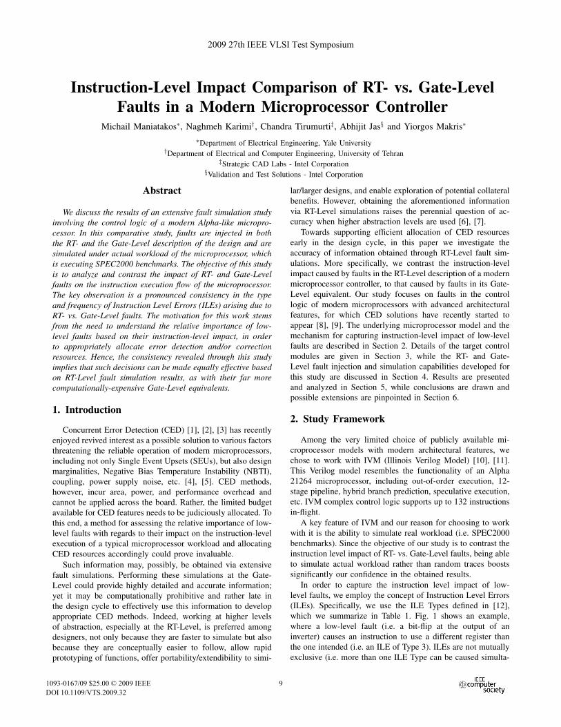
Instruction-Level Impact Comparison of RT- vs. Gate-LevelFaults in a Modern Microprocessor Controller
Michail Maniatakos∗, Naghmeh Karimi†, Chandra Tirumurti‡, Abhijit Jas§ and Yiorgos Makris∗
∗Department of Electrical Engineering, Yale University†Department of Electrical and Computer Engineering, University of Tehran
‡Strategic CAD Labs - Intel Corporation§Validation and Test Solutions - Intel Corporation
Abstract
We discuss the results of an extensive fault simulation studyinvolving the control logic of a modern Alpha-like micropro-cessor. In this comparative study, faults are injected in boththe RT- and the Gate-Level description of the design and aresimulated under actual workload of the microprocessor, whichis executing SPEC2000 benchmarks. The objective of this studyis to analyze and contrast the impact of RT- and Gate-Levelfaults on the instruction execution flow of the microprocessor.The key observation is a pronounced consistency in the typeand frequency of Instruction Level Errors (ILEs) arising due toRT- vs. Gate-Level faults. The motivation for this work stemsfrom the need to understand the relative importance of low-level faults based on their instruction-level impact, in orderto appropriately allocate error detection and/or correctionresources. Hence, the consistency revealed through this studyimplies that such decisions can be made equally effective basedon RT-Level fault simulation results, as with their far morecomputationally-expensive Gate-Level equivalents.
1. Introduction
Concurrent Error Detection (CED) [1], [2], [3] has recentlyenjoyed revived interest as a possible solution to various factorsthreatening the reliable operation of modern microprocessors,including not only Single Event Upsets (SEUs), but also designmarginalities, Negative Bias Temperature Instability (NBTI),coupling, power supply noise, etc. [4], [5]. CED methods,however, incur area, power, and performance overhead andcannot be applied across the board. Rather, the limited budgetavailable for CED features needs to be judiciously allocated. Tothis end, a method for assessing the relative importance of low-level faults with regards to their impact on the instruction-levelexecution of a typical microprocessor workload and allocatingCED resources accordingly could prove invaluable.
Such information may, possibly, be obtained via extensivefault simulations. Performing these simulations at the Gate-Level could provide highly detailed and accurate information;yet it may be computationally prohibitive and rather late inthe design cycle to effectively use this information to developappropriate CED methods. Indeed, working at higher levelsof abstraction, especially at the RT-Level, is preferred amongdesigners, not only because they are faster to simulate but alsobecause they are conceptually easier to follow, allow rapidprototyping of functions, offer portability/extendibility to simi-
lar/larger designs, and enable exploration of potential collateralbenefits. However, obtaining the aforementioned informationvia RT-Level simulations raises the perennial question of ac-curacy when higher abstraction levels are used [6], [7].
Towards supporting efficient allocation of CED resourcesearly in the design cycle, in this paper we investigate theaccuracy of information obtained through RT-Level fault sim-ulations. More specifically, we contrast the instruction-levelimpact caused by faults in the RT-Level description of a modernmicroprocessor controller, to that caused by faults in its Gate-Level equivalent. Our study focuses on faults in the controllogic of modern microprocessors with advanced architecturalfeatures, for which CED solutions have recently started toappear [8], [9]. The underlying microprocessor model and themechanism for capturing instruction-level impact of low-levelfaults are described in Section 2. Details of the target controlmodules are given in Section 3, while the RT- and Gate-Level fault injection and simulation capabilities developed forthis study are discussed in Section 4. Results are presentedand analyzed in Section 5, while conclusions are drawn andpossible extensions are pinpointed in Section 6.
2. Study Framework
Among the very limited choice of publicly available mi-croprocessor models with modern architectural features, wechose to work with IVM (Illinois Verilog Model) [10], [11].This Verilog model resembles the functionality of an Alpha21264 microprocessor, including out-of-order execution, 12-stage pipeline, hybrid branch prediction, speculative execution,etc. IVM complex control logic supports up to 132 instructionsin-flight.
A key feature of IVM and our reason for choosing to workwith it is the ability to simulate real workload (i.e. SPEC2000benchmarks). Since the objective of our study is to contrast theinstruction level impact of RT- vs. Gate-Level faults, being ableto simulate actual workload rather than random traces boostssignificantly our confidence in the obtained results.
In order to capture the instruction level impact of low-level faults, we employ the concept of Instruction Level Errors(ILEs). Specifically, we use the ILE Types defined in [12],which we summarize in Table 1. Fig. 1 shows an example,where a low-level fault (i.e. a bit-flip at the output of aninverter) causes an instruction to use a different register thanthe one intended (i.e. an ILE of Type 3). ILEs are not mutuallyexclusive (i.e. more than one ILE Type can be caused simulta-
2009 27th IEEE VLSI Test Symposium
1093-0167/09 $25.00 © 2009 IEEE
DOI 10.1109/VTS.2009.32
9
2009 27th IEEE VLSI Test Symposium
1093-0167/09 $25.00 © 2009 IEEE
DOI 10.1109/VTS.2009.32
9
2009 27th IEEE VLSI Test Symposium
1093-0167/09 $25.00 © 2009 IEEE
DOI 10.1109/VTS.2009.32
9
2009 27th IEEE VLSI Test Symposium
1093-0167/09 $25.00 © 2009 IEEE
DOI 10.1109/VTS.2009.32
9
2009 27th IEEE VLSI Test Symposium
1093-0167/09 $25.00 © 2009 IEEE
DOI 10.1109/VTS.2009.32
9
2009 27th IEEE VLSI Test Symposium
1093-0167/09 $25.00 © 2009 IEEE
DOI 10.1109/VTS.2009.32
9
2009 27th IEEE VLSI Test Symposium
1093-0167/09 $25.00 © 2009 IEEE
DOI 10.1109/VTS.2009.32
9
2009 27th IEEE VLSI Test Symposium
1093-0167/09 $25.00 © 2009 IEEE
DOI 10.1109/VTS.2009.32
9

Fig. 1. Instruction level impact of low-level fault
neously by a low-level fault) and do not reflect every possibleinstruction level error, yet they provide a comprehensive basisfor capturing incorrect behavior in the instruction executionflow. For proper classification of a low-level fault into one ormore ILE Type, information is collected from various partsof the microprocessor, including the Scheduler, the ReOrderBuffer, the Execution Units, the Scoreboard etc., as shown inTable 2. In other words, the complete microprocessor modelneeds to be simulated to ensure accurate classification. Detailsabout ILEs and the classification process can be found in [12].
The key limitation of the IVM version which supportssimulation of actual workload is that it is not synthesizable,thus limiting our logic and fault simulation options to the RT-Level. Therefore, in order to perform a comparative study ofthe instruction-level impact of RT- vs. Gate-Level faults, weconverted the target modules to synthesizable, incorporatedtheir Gate-Level version in the RT-Level model of the micro-processor, and created the necessary infrastructure for using anRT-Level logic simulator to perform fault simulation of boththeir RT- and Gate-Level versions.
3. Target ModulesSince our focus is on microprocessor control logic, we target
two key control modules: the Scheduler, which controls theallocation of instructions to execution units, and the ReOrderBuffer (ROB) which controls the order of instruction retire-ment. Both modules incorporate large buffers to support thenumber of instructions that can be in-flight, with a combinedtotal of over 40,000 storage elements, as shown in Table 3. TheScheduler is relatively small; it contains 32 slots for instructionswaiting to be executed and keeps the information needed toidentify and correctly issue an instruction. The ROB is muchlarger because it contains a 64-slot instruction buffer, as well ascomplementary information about instruction retirement order.
In order to perform a comparative RT- vs. Gate-Levelanalysis, we converted the Verilog description of these twomodules to a synthesizable version and employed Synop-sys Design Compiler to synthesize them and obtain theirGate-Level description. The synthesized Scheduler consists of170,099 standard cells, while the synthesized ROB consists of228,881 standard cells. Even though the ROB has over 20K(228%) more storage elements than the Scheduler, it only uses34% more standard cells. This is explained since, despite thefact that the ROB uses much larger buffers, the control logicinvolved is rather small and is only limited to the proper retire-ment of instructions. On the other hand, the Scheduler performs
Group 1: Type 1: Incorrect (yet valid) operation code usedOperation Errors Type 2: Invalid operation code used
Type 3: Incorrect (yet valid) register addressedGroup 2: Type 4: Invalid register addressed
Operand Errors Type 5: Premature use of register contentsType 6: Incorrect immediate operand used
Group 3: Type 7: Incorrect functional unit type utilizedExecution Errors Type 8: Multiple functional units utilized
Type 9: Early commencementGroup 4: Type 10: Late or no commencement
Timing Errors Type 11: Longer durationType 12: Shorter duration
Group 5:Order Errors
Type 13: Commitment order violation
TABLE 1. Instruction-Level Errors
Module InformationDecoder Opcode, OperandsRename Physical RegistersExecution Functional Unit UtilizationScheduler Issue Time, ReplaysScoreboard Availability of RegistersReorder Buffer (ROB) ROBid, Retirement Cycle/Order
TABLE 2. ILE classification information traced fromvarious microprocessor modules
complicated tasks such as checking whether operands are ready,whether an instruction can be issued avoiding structural hazardsetc., which involve much more control logic. This observationimplies diversity, since both control logic-heavy and buffer-heavy modules are considered in the study. Finally, using anindustrial-strength tool, we performed fault enumeration andcollapsing on the two target modules and we provide the resultsin Table 4. All faults, including faults within the cells, areconsidered.
4. Fault Simulation
With the exception of the Scheduler and the ROB modules,for which we created synthesizable versions, the rest of theIVM microprocessor is not synthesizable; therefore, Gate-Levelfault simulation tools cannot be used in our study. Even ifthe complete processor was synthesizable, fault-simulating theentire Gate-Level model would probably be impractical. Hence,we are limited to using RT-Level logic simulation tools, such asSynopsys VCS. This enables simulation of the RT-Level modelof the microprocessor while it executes actual workload, butit does not offer fault injection capabilities. In this section,we describe the methods that we employ in order to injectfaults in the RT- and Gate-Level models of the target modules,while performing RT-Level logic simulation. These methodshave been fully automated through in-house software.
4.1. RT-Level Fault Injection
In order to support RT-Level fault injection, an extra modulecalled Fault Controller is added to control all fault injectionparameters, and the RT-Level model of each target moduleis mutated. Injection is performed in every storage elementdefined in the Verilog model, as shown in Table 3. Faultinjection during RT-Level fault simulation is performed using
1010101010101010
Module # of Storage ElementsScheduler 9,411ReOrder Buffer (ROB) 30,735
TABLE 3. Statistics on RT-Level Modules
Fault Type Scheduler ReOrder BufferAll faults 1,159,012 1,714,306Unique faults 679,833 1,074,850Untestable faults 320 19,845
TABLE 4. Statistics on Gate-Level Modules
a method similar to the parallel saboteurs technique describedin [13]. Fig. 2 presents a simplified diagram of the method,which is capable of injecting either stuck-at faults, with user-defined start and stop times and duration (lighter color indicateshardware resources added for fault simulation purposes). Sincewe operate at the RT-Level model, only storage elements arefault-injected. Each storage element is driven by a MUX whichis controlled by the Fault Controller. The latter also provides anadditional fault clock signal which alters the value of the targetstorage element during the active fault injection window. Eachstorage element has a unique ID, so that the Fault Controllercan pick the one to be injected each time, while the resthold their value. The fault clock is different than the regularclock, with fault injection performed when it has a value of 1.Otherwise, the value set by the Fault Controller is ignored.
4.2. Gate-Level Fault InjectionGate-Level fault injection during RT-Level fault simulation
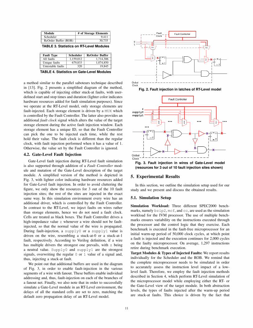
is also supported through addition of a Fault Controller mod-ule and mutation of the Gate-Level description of the targetmodule. A simplified version of the method is depicted inFig. 3, with lighter color indicating hardware resources addedfor Gate-Level fault injection. In order to avoid cluttering thefigure, we only show the resources for 3 out of the 10 faultinjection sites; the rest of the sites are injected in the exactsame way. In this simulation environment every wire has anadditional driver, which is controlled by the Fault Controller.In contrast to the RT-Level, we inject faults on wires ratherthan storage elements, hence we do not need a fault clock.Cells are treated as black boxes. The Fault Controller drives ahigh-impedance value z whenever a wire should not be fault-injected, so that the normal value of the wire is propagated.During fault-injection, a supply0 or a supply1 value isdriven on the wire, resembling a stuck-at-0 or a stuck-at-1fault, respectively. According to Verilog definition, if a wirehas multiple drivers the strongest one prevails, with z beinga neutral value. Supply0 and supply1 are the strongestsignals, overwriting the regular 0 or 1 value of a signal and,thus, injecting a stuck-at fault.
We point out that additional buffers are used in the diagramof Fig. 3, in order to enable fault-injection in the varioussegments of a wire with fanout. These buffers enable individualaddressing and, thus, fault-injection on each of the branches ofa fanout net. Finally, we also note that in order to successfullysimulate a Gate-Level module in an RT-Level environment, thedelays of all the standard cells are set to zero, matching thedefault zero propagation delay of an RT-Level model.
Fig. 2. Fault injection in latches of RT-Level model
Fig. 3. Fault injection in wires of Gate-Level model(resources for 3 out of 10 fault injection sites shown)
5. Experimental Results
In this section, we outline the simulation setup used for ourstudy and we present and discuss the obtained results.
5.1. Simulation Setup
Simulation Workload: Three different SPEC2000 bench-marks, namely bzip2, mcf, and cc, are used as the simulationworkload for the IVM processor. The use of multiple bench-marks ensures variability on the instructions executed throughthe processor and the control logic that they exercise. Eachbenchmark is executed in the fault-free microprocessor for aninitial warm-up period of 50,000 clock cycles, at which pointa fault is injected and the execution continues for 2,000 cycleson the faulty microprocessor. On average, 1,297 instructionsretire during benchmark execution.Target Modules & Types of Injected Faults: We report resultsindividually for the Scheduler and the ROB. We remind thatthe complete microprocessor needs to be simulated in orderto accurately assess the instruction level impact of a low-level fault. Therefore, we employ the fault injection methodsdescribed in Section 4, which perform RT-Level simulation ofthe microprocessor model while employing either the RT- orthe Gate-Level view of the target module. In both abstractionlevels, the types of faults injected after the warm-up periodare stuck-at faults. This choice is driven by the fact that
1111111111111111
such injected faults resemble errors occurring due to designmarginalities and in-field failures. Furthermore, their permanentnature increases the probability that they will cause an ILE,and, thereby, decreases the length of the fault simulationsnecessary to study their impact. We note, however, that thedeveloped fault injection infrastructure also supports simulationof other fault types, such as single-cycle or multi-cycle tran-sients, so a similar (yet much more computationally expensive)study can be performed for those.Number of Injected Faults: While simulating the RT-Levelversions of the two modules, all faults presented in Table 3 areinjected. At the Gate-Level, however, the number of faults inTable 4 is very large so we resort to sampling, with a samplesize of c = 10%. For the Scheduler, where the total number offaults is NScheduler = 1, 159, 012, this translates to a samplesize of nScheduler = 115, 901 faults, while for the ROB, whereNROB = 1, 714, 306 faults, this translates to a sample size ofnROB = 171, 430 faults. To assess the error incurred due tosampling, we use the following equation, defined in [14]:
C0.99 = c± ε, ε =a2k
2Ni
√1 +
4Nic(1− c)a2k
(1)
where ε is the incurred error, C0.99 is the range of faultcoverage within which the true coverage lies with a confidenceinterval of 99%, Ni is the total number of faults, c is thefraction of faults to be simulated, a = 2.60 to achievea confidence interval of 99%, and k = 1 since the totalpopulation is large. Thus, our sample size of c = 10% yieldsan error of ε = 0.015%, which is adequate for our analysis.Computational Power: The reported simulation times are ob-tained on a Quad-core Xeon 3.33GHz with 16GB of memory.
5.2. Results and Discussion
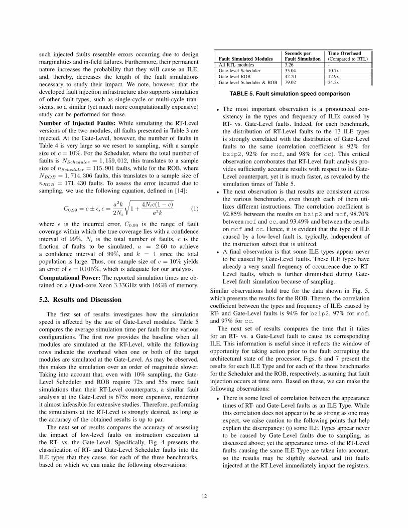
The first set of results investigates how the simulationspeed is affected by the use of Gate-Level modules. Table 5compares the average simulation time per fault for the variousconfigurations. The first row provides the baseline when allmodules are simulated at the RT-Level, while the followingrows indicate the overhead when one or both of the targetmodules are simulated at the Gate-Level. As may be observed,this makes the simulation over an order of magnitude slower.Taking into account that, even with 10% sampling, the Gate-Level Scheduler and ROB require 72x and 55x more faultsimulations than their RT-Level counterparts, a similar faultanalysis at the Gate-Level is 675x more expensive, renderingit almost infeasible for extensive studies. Therefore, performingthe simulations at the RT-Level is strongly desired, as long asthe accuracy of the obtained results is up to par.
The next set of results compares the accuracy of assessingthe impact of low-level faults on instruction execution atthe RT- vs. the Gate-Level. Specifically, Fig. 4 presents theclassification of RT- and Gate-Level Scheduler faults into theILE types that they cause, for each of the three benchmarks,based on which we can make the following observations:
Seconds per Time OverheadFault Simulated Modules Fault Simulation (Compared to RTL)All RTL modules 3.26 -Gate-level Scheduler 35.04 10.7xGate-level ROB 42.20 12.9xGate-level Scheduler & ROB 79.02 24.2x
TABLE 5. Fault simulation speed comparison
• The most important observation is a pronounced con-sistency in the types and frequency of ILEs caused byRT- vs. Gate-Level faults. Indeed, for each benchmark,the distribution of RT-Level faults to the 13 ILE typesis strongly correlated with the distribution of Gate-Levelfaults to the same (correlation coefficient is 92% forbzip2, 92% for mcf, and 98% for cc). This criticalobservation corroborates that RT-Level fault analysis pro-vides sufficiently accurate results with respect to its Gate-Level counterpart, yet it is much faster, as revealed by thesimulation times of Table 5.
• The next observation is that results are consistent acrossthe various benchmarks, even though each of them uti-lizes different instructions. The correlation coefficient is92.85% between the results on bzip2 and mcf, 98.70%between mcf and cc, and 93.49% and between the resultson mcf and cc. Hence, it is evident that the type of ILEcaused by a low-level fault is, typically, independent ofthe instruction subset that is utilized.
• A final observation is that some ILE types appear neverto be caused by Gate-Level faults. These ILE types havealready a very small frequency of occurrence due to RT-Level faults, which is further diminished during Gate-Level fault simulation because of sampling.
Similar observations hold true for the data shown in Fig. 5,which presents the results for the ROB. Therein, the correlationcoefficient between the types and frequency of ILEs caused byRT- and Gate-Level faults is 94% for bzip2, 97% for mcf,and 97% for cc.
The next set of results compares the time that it takesfor an RT- vs. a Gate-Level fault to cause its correspondingILE. This information is useful since it reflects the window ofopportunity for taking action prior to the fault corrupting thearchitectural state of the processor. Figs. 6 and 7 present theresults for each ILE Type and for each of the three benchmarksfor the Scheduler and the ROB, respectively, assuming that faultinjection occurs at time zero. Based on these, we can make thefollowing observations:
• There is some level of correlation between the appearancetimes of RT- and Gate-Level faults as an ILE Type. Whilethis correlation does not appear to be as strong as one mayexpect, we raise caution to the following points that helpexplain the discrepancy: (i) some ILE Types appear neverto be caused by Gate-Level faults due to sampling, asdiscussed above; yet the appearance times of the RT-Levelfaults causing the same ILE Type are taken into account,so the results may be slightly skewed, and (ii) faultsinjected at the RT-Level immediately impact the registers,
1212121212121212

Fig. 4. Comparison between ILE Types caused by RT- vs. Gate-Level faults in the Scheduler
Fig. 5. Comparison between ILE Types caused by RT- vs. Gate-Level faults in the ROB
while faults injected at the Gate-Level have to traversemore logic which may require infrequent combinations ofinputs, in order to reach a register.
• More importantly, due to point (ii) above, it is evidentthat it takes longer for a Gate-Level fault rather than anRT-Level fault to manifest as an ILE. Therefore, definingthe window of opportunity for taking preventive/correctiveaction based on RT-Level fault simulation analysis is apessimistic approach, whose validity and effectivenessholds for the Gate-Level faults as well.
6. Conclusion & Future DirectionsMotivated by the need to develop cost-effective CED meth-
ods for the control logic of modern microprocessors, weperformed a comparative investigation of the instruction levelimpact of RT- vs. Gate-Level faults. Our study revealed a verystrong correlation in the type and frequency of ILEs causedby RT- and Gate-Level faults, respectively. Furthermore, weobserved that the time needed for an injected RT-Level fault toappear as an ILE is a pessimistic estimate of the time it takesfor a Gate-Level fault, which typically takes longer to manifest.In addition, we demonstrated that substitution of even a singleRT-Level module with its Gate-Level equivalent results in fault
simulation which is over an order of magnitude slower perfault, as well as a large increase in the number of faults thatneed to be simulated to ensure accuracy, even when samplingis employed. Based on these observations, we conclude thatinstruction-level impact analysis of RT-Level faults providessufficiently accurate information with regards to the prevalenttypes of ILEs and the window of opportunity for avertingthem, yet earlier in the design cycle and at significantly lowercomputational cost than analysis of Gate-Level faults.
As a continuation of this study, we plan to expend the com-putational resources needed for fault-simulating the completeGate-Level fault list as opposed to the current 10% sample,experiment with more SPEC2000 benchmarks to increase thevariety of instructions executed by the microprocessor, andconvert more control modules into synthesizable versions inorder to extend the scope of our results.
AcknowledgementsThe described research is supported through a generous gift
from Intel Corporation, where it was partially carried out duringan internship by the first author. The second author performedthis research while being a visiting student at Yale University.The authors would like to thank Prof. Sanjay Patel and Nicholas
1313131313131313

Fig. 6. Comparison of time-to-appearance of RT- vs. Gate-Level faults in the Scheduler as ILE Types
Fig. 7. Comparison of time-to-appearance of RT- vs. Gate-Level faults in the ROB as ILE Types
Wang from the University of Illinois at Urbana-Champaign forproviding the IVM microprocessor and technical assistance.
References
[1] M. Goessel and S. Graf, Error Detection Circuits, McGraw-Hill,1993.
[2] S. Mitra and E. J. McCluskey, “Which concurrent error detectionscheme to choose?,” in International Test Conference, 2000, pp.985–994.
[3] S. Almukhaizim, P. Drineas, and Y. Makris, “Entropy-drivenparity-tree selection for low-overhead concurrent error detectionin finite state machines,” IEEE Transactions on Computer-AidedDesign of Integrated Circuits and Systems, vol. 25, no. 8, pp.1547–1554, 2006.
[4] C. Metra, M. Favalli, and B. Ricco, “On-line detection oflogic errors due to crosstalk, delay, and transient faults,” inInternational Test Conference, 1998, pp. 524–533.
[5] T. Karnik, P. Hazucha, and J. Patel, “Characterization of softerrors caused by single event upsets in cmos processes,” IEEETransactions on Dependable and Secure Computing, vol. 1, no.2, pp. 128–143, 2004.
[6] F. Corno, G. Cumani, M. Sonza Reorda, and G. Squillero, “AnRT-level fault model with high gate level correlation,” IEEEInternational High-Level Design Validation and Test Workshop,2000.
[7] W. Mao and R. K. Gulati, “Improving gate level fault coverage
by RTL fault grading,” International Test Conference, pp. 150–159, 1996.
[8] M. Maniatakos, N. Karimi, Y. Makris, A. Jas, and C. Tirumurti,“Design and evaluation of a timestamp-based concurrent errordetection method (CED) in a modern microprocessor controller,”IEEE International Symposium on Defect and Fault Tolerance ofVLSI Systems, pp. 454–462, Oct. 2008.
[9] C. Metra, Rossi D., Omana M., Jas A., and Galivanche R.,“Function-inherent code checking: A new low cost on-line testingapproach for high performance microprocessor control logic,”IEEE European Test Symposium, pp. 171–176, 2008.
[10] N. J. Wang, J. Quek, T. M. Rafacz, and S. J. Patel, “Char-acterizing the effects of transient faults on a high-performanceprocessor pipeline,” in International Conference on DependableSystems and Networks, 2004, pp. 61–70.
[11] N. J. Wang and S. J. Patel, “Restore: symptom based soft errordetection in microprocessors,” in International Conference onDependable Systems and Networks, 2005, pp. 30–39.
[12] N. Karimi, M. Maniatakos, Y. Makris, and A. Jas, “On thecorrelation between controller faults and instruction-level errorsin modern microprocessors,” International Test Conference, pp.24.1.1–24.1.10, 2008.
[13] J. C. Baraza, J. Gracia, S. Blanc, D. Gil, and P. J. Gil, “Enhance-ment of fault injection techniques based on the modification ofVHDL code,” IEEE Transactions on Very Large Scale Integration(VLSI) Systems, vol. 16, no. 6, pp. 693–706, 2008.
[14] D. Agrawal and H. Kato, “Fault sampling revisited,” IEEEDesign and Test, vol. 7, no. 4, pp. 32–35, 1990.
1414141414141414


