
INSTRUCTION - Campbell Sci · by a licensed and qualified electrician. ... PDF viewers: These page...
22
INSTRUCTION MANUAL CURS100 100 Ohm Current Shunt Terminal Input Module Revision: 4/17 Copyright © 1996-2017 Campbell Scientific, Inc.
Transcript of INSTRUCTION - Campbell Sci · by a licensed and qualified electrician. ... PDF viewers: These page...

INST
RU
CT
ION
MA
NU
AL
CURS100 100 Ohm Current Shunt Terminal Input Module
Revision: 4/17
C o p y r i g h t © 1 9 9 6 - 2 0 1 7C a m p b e l l S c i e n t i f i c , I n c .


Guarantee
This equipment is guaranteed against defects in materials and workmanship.
We will repair or replace products which prove to be defective during the
guarantee period as detailed on your invoice, provided they are returned to us
prepaid. The guarantee will not apply to:
Equipment which has been modified or altered in any way without the
written permission of Campbell Scientific
Batteries
Any product which has been subjected to misuse, neglect, acts of God or
damage in transit.
Campbell Scientific will return guaranteed equipment by surface carrier
prepaid. Campbell Scientific will not reimburse the claimant for costs incurred
in removing and/or reinstalling equipment. This guarantee and the Company’s
obligation thereunder is in lieu of all other guarantees, expressed or implied,
including those of suitability and fitness for a particular purpose. Campbell
Scientific is not liable for consequential damage.
Please inform us before returning equipment and obtain a Repair Reference
Number whether the repair is under guarantee or not. Please state the faults as
clearly as possible, and if the product is out of the guarantee period it should
be accompanied by a purchase order. Quotations for repairs can be given on
request. It is the policy of Campbell Scientific to protect the health of its
employees and provide a safe working environment, in support of this policy a
“Declaration of Hazardous Material and Decontamination” form will be
issued for completion.
When returning equipment, the Repair Reference Number must be clearly
marked on the outside of the package. Complete the “Declaration of
Hazardous Material and Decontamination” form and ensure a completed copy
is returned with your goods. Please note your Repair may not be processed if
you do not include a copy of this form and Campbell Scientific Ltd reserves
the right to return goods at the customers’ expense.
Note that goods sent air freight are subject to Customs clearance fees which
Campbell Scientific will charge to customers. In many cases, these charges are
greater than the cost of the repair.
Campbell Scientific Ltd,
80 Hathern Road,
Shepshed, Loughborough, LE12 9GX, UK
Tel: +44 (0) 1509 601141
Fax: +44 (0) 1509 601091
Email: [email protected]
www.campbellsci.co.uk


PLEASE READ FIRST
About this manual
Please note that this manual was originally produced by Campbell Scientific Inc. primarily for the North
American market. Some spellings, weights and measures may reflect this origin.
Some useful conversion factors:
Area: 1 in2 (square inch) = 645 mm
2
Length: 1 in. (inch) = 25.4 mm
1 ft (foot) = 304.8 mm
1 yard = 0.914 m
1 mile = 1.609 km
Mass: 1 oz. (ounce) = 28.35 g
1 lb (pound weight) = 0.454 kg
Pressure: 1 psi (lb/in2) = 68.95 mb
Volume: 1 UK pint = 568.3 ml
1 UK gallon = 4.546 litres
1 US gallon = 3.785 litres
In addition, while most of the information in the manual is correct for all countries, certain information
is specific to the North American market and so may not be applicable to European users.
Differences include the U.S standard external power supply details where some information (for
example the AC transformer input voltage) will not be applicable for British/European use. Please note,
however, that when a power supply adapter is ordered it will be suitable for use in your country.
Reference to some radio transmitters, digital cell phones and aerials may also not be applicable
according to your locality.
Some brackets, shields and enclosure options, including wiring, are not sold as standard items in the
European market; in some cases alternatives are offered. Details of the alternatives will be covered in
separate manuals.
Part numbers prefixed with a “#” symbol are special order parts for use with non-EU variants or for
special installations. Please quote the full part number with the # when ordering.
Recycling information
At the end of this product’s life it should not be put in commercial or domestic refuse but
sent for recycling. Any batteries contained within the product or used during the
products life should be removed from the product and also be sent to an appropriate
recycling facility.
Campbell Scientific Ltd can advise on the recycling of the equipment and in some cases
arrange collection and the correct disposal of it, although charges may apply for some
items or territories.
For further advice or support, please contact Campbell Scientific Ltd, or your local agent.
Campbell Scientific Ltd, 80 Hathern Road, Shepshed, Loughborough, LE12 9GX, UK
Tel: +44 (0) 1509 601141 Fax: +44 (0) 1509 601091
Email: [email protected]
www.campbellsci.co.uk


Precautions DANGER — MANY HAZARDS ARE ASSOCIATED WITH INSTALLING, USING, MAINTAINING, AND WORKING ON OR AROUND TRIPODS, TOWERS, AND ANY ATTACHMENTS TO TRIPODS AND TOWERS SUCH AS SENSORS, CROSSARMS, ENCLOSURES, ANTENNAS, ETC. FAILURE TO PROPERLY AND COMPLETELY ASSEMBLE, INSTALL, OPERATE, USE, AND MAINTAIN TRIPODS, TOWERS, AND ATTACHMENTS, AND FAILURE TO HEED WARNINGS, INCREASES THE RISK OF DEATH, ACCIDENT, SERIOUS INJURY, PROPERTY DAMAGE, AND PRODUCT FAILURE. TAKE ALL REASONABLE PRECAUTIONS TO AVOID THESE HAZARDS. CHECK WITH YOUR ORGANIZATION'S SAFETY COORDINATOR (OR POLICY) FOR PROCEDURES AND REQUIRED PROTECTIVE EQUIPMENT PRIOR TO PERFORMING ANY WORK.
Use tripods, towers, and attachments to tripods and towers only for purposes for which they are designed. Do not exceed design limits. Be familiar and comply with all instructions provided in product manuals. Manuals are available at www.campbellsci.eu or by telephoning +44(0) 1509 828 888 (UK). You are responsible for conformance with governing codes and regulations, including safety regulations, and the integrity and location of structures or land to which towers, tripods, and any attachments are attached. Installation sites should be evaluated and approved by a qualified engineer. If questions or concerns arise regarding installation, use, or maintenance of tripods, towers, attachments, or electrical connections, consult with a licensed and qualified engineer or electrician.
General • Prior to performing site or installation work, obtain required approvals and permits. Comply with all
governing structure-height regulations, such as those of the FAA in the USA.• Use only qualified personnel for installation, use, and maintenance of tripods and towers, and any
attachments to tripods and towers. The use of licensed and qualified contractors is highly recommended.• Read all applicable instructions carefully and understand procedures thoroughly before beginning work.• Wear a hardhat and eye protection, and take other appropriate safety precautions while working on or
around tripods and towers.• Do not climb tripods or towers at any time, and prohibit climbing by other persons. Take reasonable
precautions to secure tripod and tower sites from trespassers.• Use only manufacturer recommended parts, materials, and tools.
Utility and Electrical • You can be killed or sustain serious bodily injury if the tripod, tower, or attachments you are installing,
constructing, using, or maintaining, or a tool, stake, or anchor, come in contact with overhead orunderground utility lines.
• Maintain a distance of at least one-and-one-half times structure height, or 20 feet, or the distancerequired by applicable law, whichever is greater, between overhead utility lines and the structure (tripod,tower, attachments, or tools).
• Prior to performing site or installation work, inform all utility companies and have all underground utilitiesmarked.
• Comply with all electrical codes. Electrical equipment and related grounding devices should be installedby a licensed and qualified electrician.
Elevated Work and Weather • Exercise extreme caution when performing elevated work.• Use appropriate equipment and safety practices.• During installation and maintenance, keep tower and tripod sites clear of un-trained or non-essential
personnel. Take precautions to prevent elevated tools and objects from dropping.• Do not perform any work in inclement weather, including wind, rain, snow, lightning, etc.
Maintenance • Periodically (at least yearly) check for wear and damage, including corrosion, stress cracks, frayed cables,
loose cable clamps, cable tightness, etc. and take necessary corrective actions.• Periodically (at least yearly) check electrical ground connections.
WHILE EVERY ATTEMPT IS MADE TO EMBODY THE HIGHEST DEGREE OF SAFETY IN ALL CAMPBELL SCIENTIFIC PRODUCTS, THE CUSTOMER ASSUMES ALL RISK FROM ANY INJURY RESULTING FROM IMPROPER INSTALLATION, USE, OR MAINTENANCE OF TRIPODS, TOWERS, OR ATTACHMENTS TO TRIPODS AND TOWERS SUCH AS SENSORS, CROSSARMS, ENCLOSURES, ANTENNAS, ETC.

i
Table of Contents PDF viewers: These page numbers refer to the printed version of this document. Use the PDF reader bookmarks tab for links to specific sections.
1. Introduction ................................................................ 1
2. Specifications ............................................................. 1
3. Measurement Concepts ............................................. 23.1 Differential Measurement .................................................................... 3 3.2 Completing the Current Loop Circuit .................................................. 3
4. Transmitter Wiring ..................................................... 44.1 Two-Wire Transmitters ........................................................................ 4
4.1.1 Possible Ground Loop Problems ................................................... 5 4.1.2 Minimum Supply Voltage ............................................................. 5
4.2 Three-Wire Transmitters ...................................................................... 6 4.3 Four-Wire Transmitters ........................................................................ 7
5. Sensor and Programming Example .......................... 85.1 Voltage Range ...................................................................................... 8 5.2 Calculating Multiplier and Offset—An Example ................................ 8 5.3 CR1000 Program Example .................................................................. 9 5.4 CR9000(X) Program Example ........................................................... 10
Figures 1-1. CURS100 terminal input module ......................................................... 1 2-1. CURS100 schematic ............................................................................ 2 3-1. CURS100 L terminal connected to a datalogger G terminal using a
jumper wire. ...................................................................................... 4 4-1. 2-wire with datalogger power .............................................................. 54-2. 2-wire with external power .................................................................. 54-3. 2-wire supply voltage ........................................................................... 64-4. 3-wire with datalogger power .............................................................. 64-5. 3-wire with external power .................................................................. 74-6. 4-wire with datalogger power .............................................................. 74-7. 4-wire with external power .................................................................. 7
CRBasic Example 5-1. CR1000 Program Example for Sensor with 4 to 20 mA Output .......... 9


1
CURS100 100 Ohm Current Shunt Terminal Input Module
1. IntroductionTerminal input modules connect directly to the datalogger’s input terminals to provide completion resistors for resistive bridge measurements, voltage dividers, and precision current shunts. The CURS100 converts a current signal (for example, 4 to 20 mA) to a voltage that is measured by the datalogger. The 100 ohm resistor used for the current shunt allows currents up to 50 mA to be read on a ±5000 mV range (CR6, CR800, CR850, CR1000, CR3000, CR5000, CR9000X, CR9000). The CR300 allows currents up to 25 mA with a –100 to +2500 mV range.
FIGURE 1-1. CURS100 terminal input module
2. Specifications100 Ohm Shunt Resistor
Tolerance @ 25 °C: ±0.01%
Temperature coefficient: ±0.8 ppm / °C
Power rating:
Compliance:
0.25 W
View the EU Declaration of Conformity at www.campbellsci.eu/curs100

CURS100 100 Ohm Current Shunt Terminal Input Module
2
FIGURE 2-1. CURS100 schematic
The CURS100 has three pins: high, low, and ground; these pins are the correct spacing to insert directly into the datalogger’s high, low, and ground terminals (⏚ on CR6, CR300, CR800, CR850, CR1000, CR3000, CR5000, orCR9000(X)).
3. Measurement ConceptsTransmitters that have current as an output signal consist of three parts: a sensor, a current transmitter (quite often integrated with the sensor), and a power supply. The power supply provides the required power to the sensor and the transmitter. The sensor signal changes with the phenomenon being measured. The current transmitter converts the sensor signal into a current signal. The current output changes in a known way with the phenomenon being measured.
An advantage of current loop transmitters over voltage output transmitters is the current signal remains constant over long lead lengths.
Two disadvantages with current loop transmitters are as follows. First, most transmitters require constant current from the power supply, adding cost and size. Second, the conditioned output quality may not be as good as a similar unconditioned sensor being measured directly by a datalogger.
The output of the transmitter is wired so the current must flow through the 100 ohm resistor in the CURS100.
Ohm’s law describes how a voltage (V) is generated by the signal current (I) through a completion resistor (R):
V = I (R)
This voltage is measured by the datalogger.

CURS100 100 Ohm Current Shunt Terminal Input Module
3
3.1 Differential Measurement The voltage across the completion resistor is measured with the differential voltage measurement. Use VoltDiff() for the CRBasic dataloggers (for example, CR6, CR1000, CR5000, or CR9000(X)). The differential voltage measurement measures the difference in voltage between the low and high terminals. The CURS100 connects the resistor between the high and the low terminals.
3.2 Completing the Current Loop Circuit As shown in FIGURE 2-1, the 100 Ω sense resistor in the CURS100 is not connected to the adjacent ground pin that connects into the datalogger signal ground (⏚). Hence, an additional connection must be made in order to complete the loop, which is commonly done by connecting the CURS100 L terminal to a datalogger G (power ground) terminal with a jumper wire (FIGURE 3-1). Connecting the L terminal to the adjacent ground (⏚ or G) terminal on the CURS100 will result in unwanted return currents flowing into the datalogger signal ground (⏚), which could induce undesirable offset errorsin low-level, single-ended measurements. The ground (⏚ or G) terminal on the CURS100 can be used to connect cable shields to ground.
Completing the loop by connecting voltages other than ground is possible as long as the datalogger voltage input limits are not exceeded. These input limits specify the voltage range, relative to datalogger ground, which both H and L input voltages must be within in order to be processed correctly by the datalogger. The input limits are ±5 V for the CR6, CR800, CR850, CR1000, CR3000, CR5000, and CR9000(X). Hence, when measuring currents up to 50 mA with the CURS100, a connection to datalogger ground is necessary in order for the resulting (50 mA) • (100 Ω) = 5 V signal to comply with the ±5 V input limits for the CR6, CR800, CR850, CR1000, CR3000, CR5000, and CR9000(X) dataloggers. The CR300 is limited to 25 mA with a –100 to +2500 mV range.

CURS100 100 Ohm Current Shunt Terminal Input Module
4
FIGURE 3-1. CURS100 L terminal connected to a datalogger G terminal using a jumper wire.
Normally the L terminal on the CURS100 should be connected to a datalogger G terminal (power ground) with a jumper wire (FIGURE 3-1). Connecting the L terminal to the adjacent ground (⏚ or G) terminal on the CURS100 can result in unwanted returncurrents on the datalogger signal ground, which could induce undesirable offset errors in low-level, single-ended measurements. The G terminal on the CURS100 can be used to connect cable shields to ground.
4. Transmitter WiringCurrent transmitters differ mainly in how they are powered and in the relative isolation of the current output. In this section, the transmitters are grouped by the total number of wires the transmitter uses to obtain power and output the current.
4.1 Two-Wire Transmitters In a two-wire transmitter, the power supply is in series within the current loop. The transmitter regulates the amount of current that flows; the current drawn from the battery is exactly the current used as a signal.
NOTE

CURS100 100 Ohm Current Shunt Terminal Input Module
5
FIGURE 4-1. 2-wire with datalogger power
FIGURE 4-2. 2-wire with external power
4.1.1 Possible Ground Loop Problems The resistor must be grounded at the datalogger to ensure that measurements are within common mode range. The signal (or low) output on the transmitter is higher than the datalogger ground by the voltage drop across the resistor. A ground-loop error may occur if the signal output is not electrically isolated but is connected to the sensor’s case. If such a sensor is in contact with earth ground (for example, a pressure transmitter in a well or stream), an alternative path for current flow is established through earth ground to the datalogger earth ground. This path is in parallel with the path from the signal output through the resistor; hence, not all the current will pass through the resistor and the measured voltage will be too low.
4.1.2 Minimum Supply Voltage When the power supply is in the current loop, as is the case in a 2-wire transmitter, it is necessary to consider the effect of voltage drop across the resistor on the voltage applied to the transmitter.
For example, suppose a 4 to 20 mA transmitter requires at least 9 volts to operate correctly and the system is powered by a 12 volt battery. The voltage the transmitter sees is the battery voltage minus the voltage drop in the rest of the current loop. At 20 mA output, the voltage drop across the 100 ohm resistor is 2 volts. When the battery is at 12 volts, this leaves 10 volts for the

CURS100 100 Ohm Current Shunt Terminal Input Module
6
transmitter and everything is fine. However, if the battery voltage drops to 11 volts, a 20 mA current will leave just 9 volts for the transmitter. In this case, when the battery drops below 11 volts, the output of the transmitter may be in error.
FIGURE 4-3. 2-wire supply voltage
4.2 Three-Wire Transmitters A three-wire current loop transmitter has the power supply connected directly to the transmitter. The voltage of the power supply is the voltage applied to the transmitter. The current output returns to power ground. Datalogger ground is connected to sensor ground and the current output by the sensor must pass through the resistor before going to ground.
FIGURE 4-4. 3-wire with datalogger power
CURS100 100 Ohm Current Shunt Terminal Input Module
7
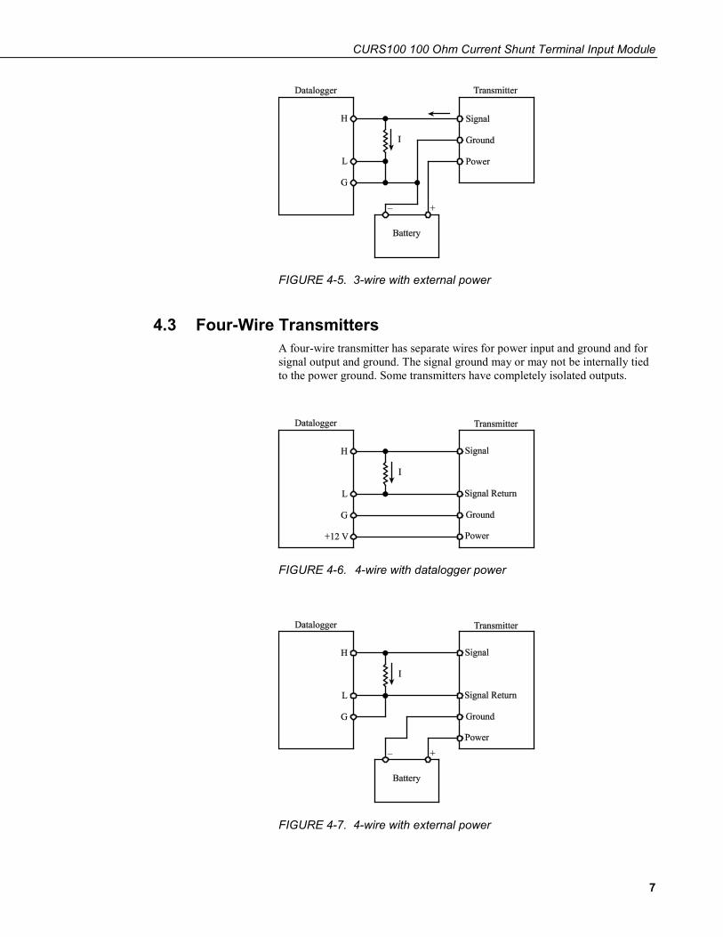
FIGURE 4-5. 3-wire with external power
4.3 Four-Wire Transmitters A four-wire transmitter has separate wires for power input and ground and for signal output and ground. The signal ground may or may not be internally tied to the power ground. Some transmitters have completely isolated outputs.
FIGURE 4-6. 4-wire with datalogger power
FIGURE 4-7. 4-wire with external power

CURS100 100 Ohm Current Shunt Terminal Input Module
8
5. Sensor and Programming ExampleIn this example, the input voltage range, and the multiplier and offset values are calculated for a 4 to 20 mA output pressure transmitter. Examples showing the differential measurement made on Channel 1 are then given for the CR1000 and CR9000(X) dataloggers; programming for the CR6, CR300, CR800, CR850, CR3000, and CR5000 is virtually identical to the CR1000.
5.1 Voltage Range The voltage range on which to make the measurement should be the smallest range that will accommodate the maximum signal the sensor will output. Using the smallest possible range will give the best resolution.
The voltage across the resistor, V, is equal to the resistance (100 ohms) multiplied by the current, I.
V = 100 I
The maximum voltage occurs at the maximum current. Thus, a 4 to 20 mA transmitter will output its maximum voltage at 20 mA.
V = 100 ohms • 0.02 A = 2 V
An output of 2 volts is measured on the ±2500 mV range on the CR800, CR850, and CR1000 or on the ±5000 mV range on the CR6, CR3000, CR5000, or CR9000(X). The 2 volt output is measured on the –100 to +2500 mV range of the CR300.
5.2 Calculating Multiplier and Offset—An Example The multiplier and the offset are the slope and y-intercept of a line and are computed with Ohm’s law and a linear fit.
For example, measure a current loop transmitter that detects pressure where the sensor specifications are as follows:
Transmitter range – 200 to 700 psi
Transmitter output range – 4 to 20 mA
The transmitter will output 4 mA at 200 psi and 20 mA at 700 psi. Using Ohm’s law, the voltage across the resistor at 200 psi is:
V = I • R
V = 0.004 • 100
V = 0.4 V or 400 mV
and at 700 psi is:
V = 0.020 • 100
V = 2.0 V or 2000 mV

CURS100 100 Ohm Current Shunt Terminal Input Module
9
Since the datalogger measures in mV, the multiplier (or slope) must be in units of psi/mV. Therefore, the y values have the units psi and the x values mV.
The equation of a line is:
(y – y1) = m (x – x1)
Solve the equation for m that is the slope of the line (or multiplier).
mpsi psi
mV mV
psi
mV=
−
−=
700 200
2000 4000 3125.
Now replace the known values to determine the intercept (or offset). Where y = m(x) + b
psib
bmVmVpsipsi
754003125.0200
4003125.0200
=×−=
+×=
m = multiplier (slope) = 0.3125 and
b = the offset (intercept) = 75.0.
5.3 CR1000 Program Example CRBasic Example 5-1. CR1000 Program Example for Sensor with 4 to 20 mA Output
'CR1000 program example for sensor with 4-20 mA output.
'Assuming a flow meter that outputs a 4-20 mA signal representing 0 - 100 gal/min, 'the voltage across the resistor at 0 gal/min = 4 mA * 100 ohms = 400 mV, 'and at 100 gal/min is 20 mA * 100 ohms = 2000 mV. The change in mV is '2000 mV - 400 mV = 1600 mV for 0 - 100 gal/min flow rate.
'The measurement result (X) for the VoltDiff instruction is mV. The 'multiplier to convert mV to gal/min is: mV * 100 gal/min / 1600 mV = 0.0625, 'the offset is 400 mV * .0625 = -25.0.
Public Measure
DataTable (Hourly,True,-1) DataInterval (0,60,Min,0) Average (1,Measure,IEEE4,0) EndTable
BeginProg Scan (1,Sec,1,0) 'Generic 4-20 mA Input measurement Measure: VoltDiff (Measure,1,mV2500,1,True,0,_60Hz,0.0625,-25.0) CallTable (Hourly) NextScan EndProg

CURS100 100 Ohm Current Shunt Terminal Input Module
10
5.4 CR9000(X) Program Example CRBasic Example 5-1 will work with the CR9000(X) datalogger with one small change. Insert the following VoltDiff() command in place of the VoltDiff() command in the program. The program will now function with the CR9000(X). This program assumes the analogue input module is installed in slot 5 for this example.
VoltDiff (Measure,1,mV5000,5,1,1,0,0,0.3125,75)


Campbell Scientific Companies
Campbell Scientific, Inc. 815 West 1800 North Logan, Utah 84321 UNITED STATES
www.campbellsci.com • [email protected]
Campbell Scientific Africa Pty. Ltd. PO Box 2450
Somerset West 7129 SOUTH AFRICA
www.campbellsci.co.za • [email protected]
Campbell Scientific Southeast Asia Co., Ltd. 877/22 Nirvana@Work, Rama 9 Road
Suan Luang Subdistrict, Suan Luang District Bangkok 10250
THAILAND www.campbellsci.asia • [email protected]
Campbell Scientific Australia Pty. Ltd. PO Box 8108
Garbutt Post Shop QLD 4814 AUSTRALIA
www.campbellsci.com.au • [email protected]
Campbell Scientific (Beijing) Co., Ltd. 8B16, Floor 8 Tower B, Hanwei Plaza
7 Guanghua Road Chaoyang, Beijing 100004
P.R. CHINA www.campbellsci.com • [email protected]
Campbell Scientific do Brasil Ltda. Rua Apinagés, nbr. 2018 ─ Perdizes CEP: 01258-00 ─ São Paulo ─ SP
BRASIL www.campbellsci.com.br • [email protected]
Campbell Scientific Canada Corp. 14532 – 131 Avenue NW Edmonton AB T5L 4X4
CANADA www.campbellsci.ca • [email protected]
Campbell Scientific Centro Caribe S.A. 300 N Cementerio, Edificio Breller
Santo Domingo, Heredia 40305 COSTA RICA
www.campbellsci.cc • [email protected]
Campbell Scientific Ltd. Campbell Park
80 Hathern Road Shepshed, Loughborough LE12 9GX
UNITED KINGDOM www.campbellsci.co.uk • [email protected]
Campbell Scientific Ltd. 3 Avenue de la Division Leclerc
92160 ANTONY FRANCE
www.campbellsci.fr • [email protected]
Campbell Scientific Ltd. Fahrenheitstraße 13
28359 Bremen GERMANY
www.campbellsci.de • [email protected]
Campbell Scientific Spain, S. L. Avda. Pompeu Fabra 7-9, local 1
08024 Barcelona SPAIN
www.campbellsci.es • [email protected]
Please visit www.campbellsci.com to obtain contact information for your local US or international representative.


![Multisim 14.1 Power Pro ComponentsMultisim 14.1 Power Pro Components Page 1 of 785 0 Ohm [CAT10-000J4LF] 0 Ohm [CAT16-000J2GLF] 0 Ohm [CAT16-000J2LF] 0 Ohm [CAT16-000J4GLF]](https://static.fdocuments.us/doc/165x107/5f50c78d85d2ce148a6061d9/multisim-141-power-pro-components-multisim-141-power-pro-components-page-1-of.jpg)


