Instruction and Assembly Manual - RC Atomic · Tools Needed (Not Included) : Equipment required :...
10
Instruction and Assembly Manual Version 1.5 (October 2016)
Transcript of Instruction and Assembly Manual - RC Atomic · Tools Needed (Not Included) : Equipment required :...
Instruction and Assembly Manual
Version 1.5 (October 2016)
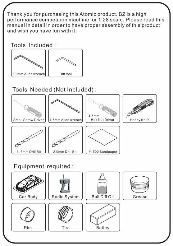
Tools Needed (Not Included) :
Equipment required :
Tools Included :
Thank you for purchasing this Atomic product. BZ is a high performance competition machine for 1:28 scale. Please read this manual in detail in order to have proper assembly of this product and wish you have fun with it.
Car Body Radio System Ball Diff Oil Grease
Rim Tire Battey
Small Screw Driver 1.5mm Allen wrench
1.3mm Allen wrench Diff tool
Hex Nut Driver4.5mm
Hobby Knife
1.5mm Drill Bit 2.0mm Drill Bit #1500 Sandpaper

1.9x4KB(Silver)
2x4KM
x8
x3
Bulkhead B (+0)
Bulkhead A (+0)
1 1
2 Apply ThrustBearing Grease
oil
Polish the diff plate and thrust bearing plate with #1500 sand paper
2.38mmThrust Ball
Diff Housing (Short)
Diff Housing (Long)
27T Pulley
Diff rubber
Diff Scwer
Pulley Collar
Diff Nut
Build 2 sets
2
Loosen
Tighten
After assembly
Diff tool
Ball differential
Attaching bulkheads
P.1
Apply Grease
Apply Ball Diff Grease
M1.9x4KB (silver color)
M1.9x4KB (silver color)
2x4KM
2x4KM
Bulkhead B (+0)
Bulkhead A (+0)
Bulkhead B (+0)
Bulkhead A (+0)
Motor Mount
Spur gear shaft
Lower deck

M1.9x4PB
Bearing hub
Bearing hub
6x10x2.5Bearing
6x10x2.5Bearing
2x6PM
2x4x0.2shims
2x5x2.5Bearing
3x6x2.5Bearing
Upper Bulkhead B (+0)
Upper Bulkhead A (+0)
16T Cnter Pulley
Drive belt (Short)
6x8 shimsAbout 0.2 mm
M1.9x4PB
6x10x2.5Bearing
Bearing hub
Bearing hub
Upper Bulkhead B (+2.5)
Upper Bulkhead A (+2.5)
Drive belt (Long)
3 3 Attaching Rear Ball differential& Center Pully
1.9x4PB (silver)
2x6PM
x4
x1
4 4 Attaching Front Ball differential
1.9x4PB (Silver)
x4
Upper Bulkhead B (+0)
Upper Bulkhead A (+0)
Upper Bulkhead B (+2.5)
Upper Bulkhead A (+2.5)
6x10x2.5Bearing
P.2
6x8 shimsAbout 0.2mm
!
!
Attention:!
Attention:!
Add 0.2 mmshims at this sideof outdrive cup.
Add 0.2 mmshims at this sideof outdrive cup.
!

5
2x4PM
1.2x4KM
x4
x4
5Attaching Upper deck
2x4PM
2x4PM
Upper deck
1.2x4KM
1.2x4KM
For Adjusting Bearing Hub
For Adjusting Bearing Hub
LoosenTighten
Loosen Tighten
Front
Rear
6 6 Attaching Steering System
2x10PMx2
2x5x2.5Bearing
Bell Crank
2x4x1washer
Makeing 2
Linkage Ball A
Linkage Ball B
2x4x0.2shims
2x10PM
Steering SystemMount
Crank Link
Attention:Installation direction
!!
P.3
Adjust the bearing hubposition to adjust belt tension. Middle is the recommended.
Make sure the carbon top deck can beeasily put on the bulk head. otherwise, use sand paper to trim the end of top deck.

Attention:!
Motor
7 7 Attaching Servo Mount
2x4PM
2x4KM
x5
x2
1.5x6PBx1
8
8 Attaching Spur gear & Motor gear
2x4PM2x4KM
2x4KM
2x4KM
2x4PM
1.5x6PB
Servo(AMZ-OP024)
Servo Mount A
Servo Mount B
Steering System
Linkage assembly
1.5x11 set screw
2.5mm Ball end
Linkage Ball A
Servo horn
1.5x11Set screw
x1
Quick
Smooth
Steering Respond
!
Attention:Installation direction
chamfer
Planar
chamfer
Planar
!
Motor
Motor pinion
Spur gear5x7x1mmO-ring
2x4KMx4
5x7x1mmO-ring
x1
Servo assembly
P.4
!
�� 14 15 16 17 18
54 5.70 5.36 5.06
56 6.75 6.30 5.91 5.56 5.25
58 7.53 6.99 6.53 6.12 5.76 5.44
Motor Pinion
Spur Gear
(5.91 is recommended for 5000KV motor)
( )Spur gear
x 1.69Motor gear
= Gear ratio
Carefully adjustthe position of pinion, make sureit does not touchthe front belt.
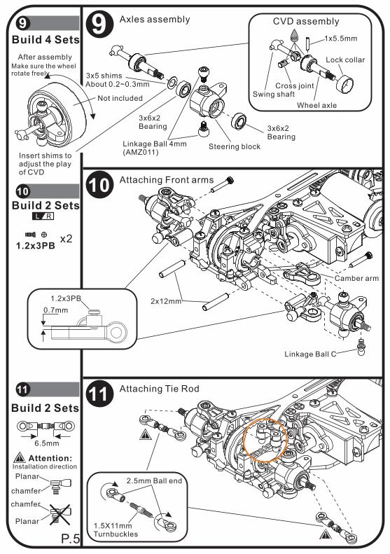
9 9 Axles assembly
3x5 shimsAbout 0.2~0.3mm
3x6x2Bearing 3x6x2
Bearing
Steering blockLinkage Ball 4mm(AMZ011)
10 Attaching Front arms
Wheel axle
Swing shaftCross joint
Lock collar
oil
CVD assembly
1x5.5mm
After assemblyMake sure the wheelrotate freely.
Insert shims toadjust the playof CVD
10
L R
0.7mm
11 Attaching Tie Rod11
1.2x3PBx2
1.2x3PB 2x12mm
Linkage Ball C
Camber arm
1.5X11mmTurnbuckles
2.5mm Ball end
6.5mm
Build 2 Sets
!
Attention:Installation direction
chamfer
Planar
chamfer
Planar
!
!
Not included
Build 2 Sets
Build 4 Sets
P.5
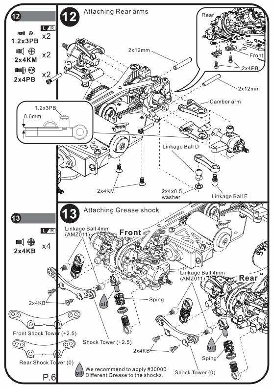
12Attaching Rear arms
12
L R
1.2x3PBx2
2x4KMx2
2x4PBx2
2x12mm
Camber arm
Linkage Ball D
Linkage Ball E2x4x0.5washer
2x4KM
2x12mm
2x4PB
Rear
Front
13 Attaching Grease shock
13
L R Front
Rear
2x4KBx4
Front Shock Tower (+2.5)
Rear Shock Tower (0)
Shock Tower (+2.5)
Linkage Ball 4mm (AMZ011)
2x4KB
Shock Tower (0)
2x4KB
0.6mm
1.2x3PB
Sping
Spingoil
oil
Linkage Ball 4mm (AMZ011)
P.6oil
We recommend to apply #30000Different Grease to the shocks.

2x6KBx2
15 15 Attaching Front Body Mount
2x4KBx3
2x4PBx2
14 14 Attaching other parts
2x4KB
2x4PB
2x4PB
Double-sided Tapes
Speed controller w/ RX
2x6KB
Not included
Trim this part to avoid the touch of front belt
P.7
Caution:Trim the front bodymount a little bitto give space for the front belt.
www.rcatomic.com
End of Assembly