Institutionen för datavetenskap - DiVA...
109
Institutionen för datavetenskap Department of Computer and Information Science Final thesis Functional Reactive Programming as programming model for telecom server software by Klervie Toczé LiTH-IDA/ERASMUS-A--14/003—SE 2014-12-18 Linköpings universitet SE-581 83 Linköping, Sweden Linköpings universitet 581 83 Linköping
Transcript of Institutionen för datavetenskap - DiVA...

Institutionen för datavetenskap Department of Computer and Information Science
Final thesis
Functional Reactive Programming as
programming model for telecom server
software
by
Klervie Toczé
LiTH-IDA/ERASMUS-A--14/003—SE
2014-12-18
Linköpings universitet
SE-581 83 Linköping, Sweden
Linköpings universitet
581 83 Linköping

Linköping University
Department of Computer and Information Science
Final Thesis
Functional Reactive Programming as
programming model for telecom server
software
by
Klervie Toczé
LiTH-IDA/ERASMUS-A--14/003—SE
2014-12-18
Supervisor: Maria Vasilevskaya
Examiner: Simin Nadjm-Tehrani

Abstract
This thesis studies the use of the functional reactive programming (FRP) framework reactive-banana in a prototype which simulates a part of a Long-Term Evolution (LTE) base station: theRadio Resource Control connection setup procedure. The investigated problem is to determinewhether using this FRP framework leads to an implementation with suitable performance andimproved maintainability compared to the current implementation. Enhancing the maintain-ability of the base station software enables quicker and more efficient maintenance activities,which lead to an improved customer satisfaction. Moreover, it means that less programmersneed to work on maintenance, so they can work on developing new products instead.
In order to compare the use of the FRP paradigm to the one currently used in the basestation implementation, the object-oriented programming (OOP) paradigm, a second prototypeusing this paradigm was also implemented. Having two prototypes implementing the samedesigned reference model (which is a simplified version of the Radio Resource Control connectionsetup procedure) enables a relevant comparison of the two paradigms. The two prototypes werethen compared in terms of performance and maintainability. The maintainability evaluationconsisted in using both software metrics and experts’ assessment, as this has been proven tobe the most efficient way to evaluate software maintainability. Four experts were asked to fillin a questionnaire after reviewing the code of the two implementations.
The comparison of the two prototypes indicates that the FRP prototype is more maintain-able than the OOP one, but the OOP prototype has better performances than the FRP one.Moreover, the performance of the FRP prototype during the conducted tests indicates thatsuch an implementation of the FRP paradigm is not suitable for a real base station.
Acknowledgements
First I would like to thank my thesis examiner, professor Simin Nadjm-Tehrani, for letting mework on this thesis topic and for her useful insights given along the thesis work. I also thank myuniversity supervisor, Maria Vasilevskaya, for our productive discussions and her useful piecesof advice. Thanks also for your comments on this report. Furthermore, I thanks KristianSandahl for his advice on the different questionnaires used in the thesis work.
Then, I would like to thank my supervisor at Ericsson, Patrik Sandahl, particularly forbeing always available and very helpful when a problem or question arose. I also want to thankall the Ericsson experts who found some time in their very busy schedules for contributing tomy thesis. Thanks a lot as well to all my colleagues at 3Gsim for being very welcoming andhelping me a lot to improve my Swedish. Tack så mycket!
I would also like to thank Michael for his great support and understanding, particularlyduring the report writing period.
Finally, my studies in a whole and this thesis work in particular would have been a lotmore difficult to achieve without the support and encouragement of my family. I will alwaysbe immensely grateful for that.
Klervie ToczéLinköping, Sweden
January, 2015
ii

Contents
1 Introduction 11.1 Motivation . . . . . . . . . . . . . . . . . . . . . . . . . . . . . . . . . . . . . . . 11.2 Problem definition . . . . . . . . . . . . . . . . . . . . . . . . . . . . . . . . . . 21.3 Goals . . . . . . . . . . . . . . . . . . . . . . . . . . . . . . . . . . . . . . . . . 21.4 Methodology . . . . . . . . . . . . . . . . . . . . . . . . . . . . . . . . . . . . . 21.5 Intended Audience . . . . . . . . . . . . . . . . . . . . . . . . . . . . . . . . . . 31.6 Limitations . . . . . . . . . . . . . . . . . . . . . . . . . . . . . . . . . . . . . . 31.7 Thesis outline . . . . . . . . . . . . . . . . . . . . . . . . . . . . . . . . . . . . . 4
2 Telecom application background 52.1 Long-Term Evolution architecture . . . . . . . . . . . . . . . . . . . . . . . . . . 5
2.1.1 Long-Term Evolution network overview . . . . . . . . . . . . . . . . . . 62.1.2 eNodeB architecture . . . . . . . . . . . . . . . . . . . . . . . . . . . . . 6
2.2 Radio Resource Control Protocol . . . . . . . . . . . . . . . . . . . . . . . . . . 72.2.1 Location in the protocol stack . . . . . . . . . . . . . . . . . . . . . . . . 72.2.2 States of the User Equipment . . . . . . . . . . . . . . . . . . . . . . . . 82.2.3 Connection setup procedure . . . . . . . . . . . . . . . . . . . . . . . . . 8
3 Functional Reactive Programming 103.1 Functional Programming . . . . . . . . . . . . . . . . . . . . . . . . . . . . . . . 103.2 Reactive Programming . . . . . . . . . . . . . . . . . . . . . . . . . . . . . . . . 113.3 Functional Reactive Programming . . . . . . . . . . . . . . . . . . . . . . . . . 12
3.3.1 Evolution of the FRP paradigm . . . . . . . . . . . . . . . . . . . . . . . 123.3.2 Advantages and disadvantages of FRP . . . . . . . . . . . . . . . . . . . 15
3.4 Alternative approaches for reactive programming . . . . . . . . . . . . . . . . . 153.4.1 Akka . . . . . . . . . . . . . . . . . . . . . . . . . . . . . . . . . . . . . . 153.4.2 Erlang . . . . . . . . . . . . . . . . . . . . . . . . . . . . . . . . . . . . . 163.4.3 ReactiveML . . . . . . . . . . . . . . . . . . . . . . . . . . . . . . . . . . 16
3.5 FRP and the telecom servers . . . . . . . . . . . . . . . . . . . . . . . . . . . . 16
4 Survey of the FRP frameworks 184.1 Methodology . . . . . . . . . . . . . . . . . . . . . . . . . . . . . . . . . . . . . 184.2 Presentation of the preliminary selected frameworks . . . . . . . . . . . . . . . 19
4.2.1 Scala.React . . . . . . . . . . . . . . . . . . . . . . . . . . . . . . . . . . 194.2.2 Reactive-banana . . . . . . . . . . . . . . . . . . . . . . . . . . . . . . . 204.2.3 Yampa . . . . . . . . . . . . . . . . . . . . . . . . . . . . . . . . . . . . . 20
iii

iv CONTENTS
4.2.4 TimeFlies . . . . . . . . . . . . . . . . . . . . . . . . . . . . . . . . . . . 214.3 Result of the survey . . . . . . . . . . . . . . . . . . . . . . . . . . . . . . . . . 22
5 Prototype design and implementation 235.1 Methodology . . . . . . . . . . . . . . . . . . . . . . . . . . . . . . . . . . . . . 235.2 Reference model . . . . . . . . . . . . . . . . . . . . . . . . . . . . . . . . . . . 24
5.2.1 Simplified RRC connection setup procedure . . . . . . . . . . . . . . . . 245.2.2 System architecture . . . . . . . . . . . . . . . . . . . . . . . . . . . . . 265.2.3 Deployment details . . . . . . . . . . . . . . . . . . . . . . . . . . . . . . 265.2.4 Simulation parameters . . . . . . . . . . . . . . . . . . . . . . . . . . . . 27
5.3 Implementations . . . . . . . . . . . . . . . . . . . . . . . . . . . . . . . . . . . 275.3.1 FRP implementation . . . . . . . . . . . . . . . . . . . . . . . . . . . . . 275.3.2 OOP implementation . . . . . . . . . . . . . . . . . . . . . . . . . . . . . 32
6 Performance evaluation 386.1 Key performance indicators . . . . . . . . . . . . . . . . . . . . . . . . . . . . . 386.2 Methodology . . . . . . . . . . . . . . . . . . . . . . . . . . . . . . . . . . . . . 38
6.2.1 Testing environment . . . . . . . . . . . . . . . . . . . . . . . . . . . . . 386.2.2 Testing procedure . . . . . . . . . . . . . . . . . . . . . . . . . . . . . . 396.2.3 Testing scenarios . . . . . . . . . . . . . . . . . . . . . . . . . . . . . . . 39
6.3 Results . . . . . . . . . . . . . . . . . . . . . . . . . . . . . . . . . . . . . . . . . 396.3.1 Results for Scenario 1 . . . . . . . . . . . . . . . . . . . . . . . . . . . . 406.3.2 Results for Scenario 2 . . . . . . . . . . . . . . . . . . . . . . . . . . . . 45
7 Maintainability evaluation 497.1 Expert evaluation - Initial thoughts . . . . . . . . . . . . . . . . . . . . . . . . . 49
7.1.1 Methodology . . . . . . . . . . . . . . . . . . . . . . . . . . . . . . . . . 497.1.2 Outcome . . . . . . . . . . . . . . . . . . . . . . . . . . . . . . . . . . . 51
7.2 Expert evaluation - Assessment . . . . . . . . . . . . . . . . . . . . . . . . . . . 527.2.1 Methodology . . . . . . . . . . . . . . . . . . . . . . . . . . . . . . . . . 527.2.2 Outcome . . . . . . . . . . . . . . . . . . . . . . . . . . . . . . . . . . . 55
7.3 Software Metrics . . . . . . . . . . . . . . . . . . . . . . . . . . . . . . . . . . . 627.3.1 Methodology . . . . . . . . . . . . . . . . . . . . . . . . . . . . . . . . . 627.3.2 Outcome . . . . . . . . . . . . . . . . . . . . . . . . . . . . . . . . . . . 63
7.4 Conclusion of the maintainability evaluation . . . . . . . . . . . . . . . . . . . . 65
8 Conclusions and future work 678.1 Conclusions . . . . . . . . . . . . . . . . . . . . . . . . . . . . . . . . . . . . . . 678.2 Future investigations . . . . . . . . . . . . . . . . . . . . . . . . . . . . . . . . . 68
8.2.1 About performance . . . . . . . . . . . . . . . . . . . . . . . . . . . . . . 688.2.2 About maintainability . . . . . . . . . . . . . . . . . . . . . . . . . . . . 698.2.3 About the FRP paradigm in general . . . . . . . . . . . . . . . . . . . . 698.2.4 About the prototypes . . . . . . . . . . . . . . . . . . . . . . . . . . . . 69
8.3 Personal reflection on the thesis work . . . . . . . . . . . . . . . . . . . . . . . . 69
Appendix A Survey of the frameworks 76
CONTENTS v
Appendix B Messaging sequences 78
Appendix C Content of the UE context 80
Appendix D Interview questionnaires 81D.1 Preliminary questionnaire . . . . . . . . . . . . . . . . . . . . . . . . . . . . . . 81D.2 Interview questionnaire . . . . . . . . . . . . . . . . . . . . . . . . . . . . . . . . 82
Appendix E Evaluation questionnaire 85
Appendix F Analysis of the maintainability assessment 93F.1 Answers frequencies . . . . . . . . . . . . . . . . . . . . . . . . . . . . . . . . . 93F.2 Descriptive statistics . . . . . . . . . . . . . . . . . . . . . . . . . . . . . . . . . 94

List of Figures
2.1 High-level overview of a LTE network . . . . . . . . . . . . . . . . . . . . . . . 62.2 High-level overview of a LTE base station . . . . . . . . . . . . . . . . . . . . . 72.3 Uu control-plane protocol stack . . . . . . . . . . . . . . . . . . . . . . . . . . . 72.4 Messaging sequence of a successful connection setup procedure in the reference
model . . . . . . . . . . . . . . . . . . . . . . . . . . . . . . . . . . . . . . . . . 9
5.1 Overview of the reference model . . . . . . . . . . . . . . . . . . . . . . . . . . . 265.2 Deployment view of the reference model . . . . . . . . . . . . . . . . . . . . . . 275.3 Module coupling in the FRP prototype . . . . . . . . . . . . . . . . . . . . . . . 285.4 Class diagram of the OOP prototype . . . . . . . . . . . . . . . . . . . . . . . . 33
6.1 Average total time (with standard deviation) elapsed on the UE side for poweringon given numbers of UEs (FRP prototype) . . . . . . . . . . . . . . . . . . . . . 40
6.2 Average time (with standard deviation) elapsed on the UE side for attaching aUE in the FRP prototype for 100, 500 and 1000 UEs powered on . . . . . . . . 41
6.3 Average productivity (with standard deviation) of the FRP prototype programsaccording to the number of UEs powered on . . . . . . . . . . . . . . . . . . . . 42
6.4 Average productivity (with standard deviation) of the FRP prototype programs(with classic functional UE program) according to the number of UEs powered on 43
6.5 Average total time elapsed on the UE side for powering on given numbers of UEs(FRP prototype with classic functional UE program) . . . . . . . . . . . . . . . 43
6.6 Average time (with standard deviation) elapsed on the UE side for attaching aUE in the FRP prototype (with classic functional UE program) for 100, 500 and1000 UEs powered on . . . . . . . . . . . . . . . . . . . . . . . . . . . . . . . . . 44
6.7 Average total time elapsed on the UE side for powering on given numbers of UEs(OOP prototype) . . . . . . . . . . . . . . . . . . . . . . . . . . . . . . . . . . . 44
6.8 Average time (with standard deviation) elapsed on the UE side for attaching aUE in the OOP prototype for 100, 500 and 1000 UEs powered on . . . . . . . . 45
6.9 Average time elapsed on the UE side for attaching a UE in the FRP prototype 466.10 Average percentage (with standard deviation) of CPU time (CPU) and available
physical memory (MEM) used by the eNodeB program in the FRP prototype . 476.11 Average time elapsed on the UE side for attaching a UE in the OOP prototype 476.12 Average percentage (with standard deviation) of CPU time (CPU) and available
physical memory (MEM) used by the eNodeB program in the OOP prototype . 48
7.1 Average score on each question for both prototypes . . . . . . . . . . . . . . . . 587.2 Frequencies of the answers to question 32 . . . . . . . . . . . . . . . . . . . . . 59
vi

LIST OF FIGURES vii
7.3 Frequencies of the answers to question 33 . . . . . . . . . . . . . . . . . . . . . 607.4 Frequencies of the answers to question 34 . . . . . . . . . . . . . . . . . . . . . 607.5 Frequencies of the answers to question 35 . . . . . . . . . . . . . . . . . . . . . 617.6 Frequencies of the answers to question 36 . . . . . . . . . . . . . . . . . . . . . 61
B.1 Messaging sequence during a failed connection setup procedure: rejection of theRRC connection request . . . . . . . . . . . . . . . . . . . . . . . . . . . . . . . 78
B.2 Messaging sequence during a failed connection setup procedure: failure of thesecurity mode . . . . . . . . . . . . . . . . . . . . . . . . . . . . . . . . . . . . . 79
B.3 Messaging sequence during a failed connection setup procedure: failure of theRRC connection reconfiguration . . . . . . . . . . . . . . . . . . . . . . . . . . . 79
List of Tables
5.1 Content of two successive messages . . . . . . . . . . . . . . . . . . . . . . . . . 255.2 Data stored in each UE . . . . . . . . . . . . . . . . . . . . . . . . . . . . . . . 25
7.1 Types of question examples from the interview questionnaire . . . . . . . . . . . 507.2 Table explaining the meaning of the different scale items. . . . . . . . . . . . . 547.3 Maintainability levels according to the score on a question . . . . . . . . . . . . 567.4 Mean and standard deviation for the OOP prototype . . . . . . . . . . . . . . . 567.5 Mean and standard deviation for the FRP prototype . . . . . . . . . . . . . . . 577.6 Questions for the second task . . . . . . . . . . . . . . . . . . . . . . . . . . . . 597.7 Code size metrics in the FRP implementation . . . . . . . . . . . . . . . . . . . 637.8 Code size metrics in the OOP implementation . . . . . . . . . . . . . . . . . . . 64
A.1 Framework list summarizing the preliminary selection outcome . . . . . . . . . 76A.2 Characteristics needed for the framework to be chosen . . . . . . . . . . . . . . 77
C.1 Data stored for each UE in the MME . . . . . . . . . . . . . . . . . . . . . . . . 80C.2 Data stored for each UE in the eNodeB . . . . . . . . . . . . . . . . . . . . . . 80
F.1 Frequencies of the answers for the OOP prototype . . . . . . . . . . . . . . . . 93F.2 Frequencies of the answers for the FRP prototype . . . . . . . . . . . . . . . . . 94F.3 Descriptive statistics for the OOP prototype . . . . . . . . . . . . . . . . . . . . 94F.4 Descriptive statistics for the FRP prototype . . . . . . . . . . . . . . . . . . . . 95
viii

List of Snippets
4.1 Currency converter example implemented in Scala.React . . . . . . . . . . . . . 194.2 Currency converter example implemented in reactive-banana . . . . . . . . . . . 204.3 Currency converter example implemented in Yampa . . . . . . . . . . . . . . . 214.4 Currency converter example implemented in TimeFlies . . . . . . . . . . . . . . 215.1 Creating and powering up several UEs . . . . . . . . . . . . . . . . . . . . . . . 295.2 Set up of the event network . . . . . . . . . . . . . . . . . . . . . . . . . . . . . 295.3 Message reception decoding and sending to the event network . . . . . . . . . . 305.4 Handling of the RRC Connection Request message . . . . . . . . . . . . . . . . 305.5 Partial set up of the epoll instance . . . . . . . . . . . . . . . . . . . . . . . . . 335.6 Reception, decoding and handling beginning of one UE message . . . . . . . . . 345.7 Extract of the handleUeMessage function . . . . . . . . . . . . . . . . . . . . 355.8 Function handleRrcConnectionRequest . . . . . . . . . . . . . . . . . . . 35
ix

List of Acronyms
2G second generation.
3G third generation.
3GPP 3rd Generation Partnership Project.
4G fourth generation.
AFOTEC Air Force Operational Test and Evaluation Center.
AFRP Arrowized FRP.
API Application Programming Interface.
C-RNTI Cell-Radio Network Temporary Identifier.
CPU Central Processing Unit.
E-FRP Event-driven FRP.
E-UTRAN Evolved UMTS Terrestrial Radio Access Network.
EPC Evolved Packet Core.
FRP Functional Reactive Programming.
GCC GNU Compiler Collection.
GHC Glasgow Haskell Compiler.
GUI Graphical User Interface.
IMSI International Mobile Subscriber Identity.
JVM Java Virtual Machine.
LTE Long-Term Evolution.
MAC Medium Access Control.
x

Acronyms xi
MME Mobility Management Entity.
OOP Object-Oriented Programming.
P-FRP Priority-based FRP.
PDCP Packet Data Convergence Protocol.
PHY physical layer.
RAM Random-Access Memory.
RLC Radio Link Control.
RNTI Radio Network Temporary Identifier.
RRC Radio Resource Control.
RT-FRP Real-time FRP.
SRB Signalling Radio Bearer.
TCP Transmission Control Protocol.
UE User Equipment.
UEH User Equipment Handling.
UMTS Universal Mobile Telecommunication System.

Chapter 1
Introduction
This thesis work (30 ECTS) was done in partial fulfilment of a French engineering degree inComputer Science at the University of Technology of Compiègne and of a master degree inComputer Science at Linköping University. It was examined at Linköping University, Depart-ment of Computer and Information Science, as part of a dual degree programme. The workwas carried out at Ericsson in Linköping
Nowadays, telecommunication systems involve lots of complex software components. Thetelecom protocols themselves are complex but the fact that they are programmed using tradi-tional software engineering techniques adds even more complexity, called accidental complexity[20], to the whole program. Indeed, the current programming model used in the telecom serversdoesn’t handle events and other reactive behaviours, which are the core of the telecom proto-cols, without a lot of additional code dedicated to them. This creates a program that is morecomplex than strictly needed and thus, less readable and maintainable. The aim of this thesisis to investigate a new programming model which could lead to a less complex code for thetelecom servers.
Functional Reactive Programming (FRP) is a quite new programming model [28] whichis dedicated to deal with reactive systems. It has already successful applications in differentdomains such as Graphical User Interfaces (GUIs), video games, and robotics. The aim of thisthesis is to determine whether this programming model can be used in the telecom servers aswell.
1.1 Motivation
Reducing as much as possible the accidental complexity of the telecom servers is very importantas it is closely associated to increased maintainability. First, this is beneficial because theresources (and the associated cost) that are no longer needed to be spent on maintenance taskscan be used to create new products with added value. Secondly, if the maintenance tasks areeasier to perform for the programmer, it will lead to a more efficient and quicker maintenancewhich will increase customer satisfaction.
1

2 CHAPTER 1. INTRODUCTION
1.2 Problem definition
The question addressed in this thesis is whether using Functional Reactive Programming as aprogramming model leads to a suitably performing and more maintainable program comparedto the current Object Oriented Programming paradigm. To address the problem in the telecomcontext, the implementation of the Radio Resource Control protocol in a Long-Term Evolutionbase station will be considered.
1.3 Goals
The goals which were set for the thesis were the following:
• To perform a theoretical investigation of FRP to find out how this programming modelrelates to reactive behaviours typical for telecom server software.
• To survey the existing FRP frameworks, in particular, the Haskell framework reactive-banana [6] and the Scala framework Scala.React [39] in order to select the most appro-priate for implementing a prototype.
• To develop one prototype showing how a typical reactive pattern from telecom softwarecan look like when implemented in a FRP framework.
• To develop one prototype showing how the same reactive pattern can look like whenimplemented with the currently-used object-oriented programming paradigm.
• To compare the performance of both prototypes, together with insights about the per-formance of the current telecom server software, in order to determine whether the FRPprototype performs suitably.
• To obtain insights about the current telecom server software maintainability in order toknow which maintainability characteristics are the most important.
• To compare the maintainability of the two prototypes using both expert assessment andsoftware metrics.
1.4 Methodology
The thesis began by a study of the connection setup procedure of the Radio Resource Control(RRC) protocol, the part of the Long-Term Evolution (LTE) base station which is modelledin the thesis. The aim was to get familiar with the procedure and also to identify its typicalreactive behaviours.
The thesis continued with a literature study of FRP. The aim was to get to know thisprogramming paradigm and to select a suitable framework for implementing the referencemodel. The selection was made according to criteria such as the amount of documentation andexample available and the type of applications already using the framework. It was done firstusing the literature specific to the frameworks and then completed by small experimentationsfor four pre-selected frameworks. This approach was chosen due to time limitation which madeexperimenting with every framework impossible. Moreover, practical experimentations were

1.5. INTENDED AUDIENCE 3
carried out to know if the frameworks were usable in practice. More details can be found inSection 4.1.
Then, in order to stay within the thesis timeframe, a simplified reference model, focusingon the typical reactive behaviours of the modelled procedure, was derived from this complexprocedure. Two prototypes were developed using the FRP and the Object-Oriented Program-ming (OOP) paradigms in order to compare two implementations of the same reference model.More details can be found in Section 5.1.
Last but not least, the two prototypes were evaluated. First, the performance of the proto-types was evaluated using key performance indicators (detailed in Section 6.1) related to time,Central Processing Unit (CPU) and memory use of the programs. Those key performanceindicators where chosen because they were the ones interesting with regards to the real basestation implementation. The performance was evaluated during a peak load scenario and aspread load scenario is order to cover the two types of situations a base station can experience.More details can be found in Section 6.2. Then the maintainability of the two prototypes wasevaluated using expert assessments and software metrics. This combination of evaluation waschosen as the literature reviewed presents it as the best way to perform a software maintain-ability evaluation [13]. Experts working on the real base station were first interviewed in orderto know which maintainability characteristics are the most important in the real base station.It was chosen to begin by asking people involved everyday with the real implementation inorder to focus on the characteristics important in practice for such a software during the rest ofthe evaluation (more details can be found in Section 7.1.1). Then other software experts wereasked to evaluate the maintainability of the two prototypes using a questionnaire (more detailscan be found in Section 7.2.1). Finally software metrics related to code size were calculated(more details can be found in Section 7.3.1).
In order to answer the thesis problem, a higher or lower maintainability of the FRP pro-totype will be achieved if both the software metrics and the expert assessment results are inagreement. For its performance to be considered suitable, the FRP prototype performanceshould exceed the performance expected in the real base station, as it implements a simpli-fied procedure. Having better performance than the OOP prototype is not required for theperformance to be suitable.
1.5 Intended Audience
This thesis is intended to be understandable by anyone without prior knowledge of telecomapplications but with basic programming knowledge. Being familiar with object-oriented andfunctional programming is an advantage but already knowing the FRP paradigm is not requiredas it will be presented.
1.6 Limitations
The intent of this thesis was not to reimplement the whole LTE base station using functionalreactive programming, but to focus on the parts of this implementation dealing with eventhandling. Thus, the prototypes are implementing only a simplified version of a procedurewhich is part of one of the protocols used in the base station: the RRC connection setupprocedure.

4 CHAPTER 1. INTRODUCTION
1.7 Thesis outline
This thesis is organized as follows:
• The chapter 2 will describe the telecom application background of the thesis, including apresentation of the LTE base station and of the RRC connection setup procedure.
• The chapter 3 will present the functional reactive programming paradigm, as well asrelated works.
• The chapter 4 will explain how the survey of the FRP frameworks was conducted andpresent its outcome.
• The chapter 5 will present the reference model used for the design of the two prototypesand details about their implementations.
• The chapter 6 will explain how the performance evaluation of the two prototypes wasperformed and describe its outcomes.
• The chapter 7 will describe the maintainability evaluation of the two prototypes and itsoutcomes.
• The chapter 8 will present the conclusions of the thesis work and ideas for future inves-tigations.

Chapter 2
Telecom application background
This thesis was carried out within a specific field of application: the telecom servers. In thischapter, basic background about these telecom servers will be given.
2.1 Long-Term Evolution architecture
The telecom server architecture used in the thesis is the LTE architecture. LTE is a standardfor wireless data communications technology. It is the latest evolution of the Universal MobileTelecommunication System (UMTS) standard, commonly called third generation (3G).
The LTE standard is developed by the 3rd Generation Partnership Project (3GPP), whichis a collaboration between six telecommunications standard development organizations basedin different parts of the world. One of the primary goals of this collaboration is to haveglobally applicable standards for mobile communications, on the contrary to the first andsecond generations where several technologies were deployed nationally or regionally [1].
Driven by the growing popularity of smartphones and other mobile devices, the aim of theLTE was to increase the capacity and speed of wireless data networks, as well as to simplify thenetwork architecture. It uses a larger wireless spectrum than the precedent second generation(2G) and 3G standards, meaning that both the users and the operators need to invest incompatible equipments to use the new features of the LTE.
The first LTE standard (Release 8) was finalized in December 2008. It has been greatlyimproved with the release 10, finalized in March 2011, thus taking the name of LTE-Advancedfrom this release. This improved version of the standard complies with the requirements set bythe International Telecommunication Union in order to belong to the fourth generation (4G).However, this version of the standard is backwards compatible so LTE, and LTE-Advancedterminals can both use either LTE or LTE-Advanced networks [1]. Some improvements ofLTE-Advanced are [62]:
• an increased peak data rate beyond 1 Gbps
• a higher spectral efficiency
• an increased number of simultaneously active subscribers
• improved performance at cell edges.
This thesis considers the release 12 of the 3GPP standard.
5

6 CHAPTER 2. TELECOM APPLICATION BACKGROUND
Figure 2.1: High-level overview of a LTE network
2.1.1 Long-Term Evolution network overview
The LTE network architecture is composed of three main high-level components [57]:
• the User Equipment (UE)
• the Evolved UMTS Terrestrial Radio Access Network (E-UTRAN)
• the Evolved Packet Core (EPC)
The UE is the device that the end-user uses to communicate over the network. It can be amobile phone but also a mobile broadband adapter used by a computer, a tablet or any otherdevice.
The E-UTRAN is the access part of the network. It handles the radio communicationsbetween the UEs and the EPC. The E-UTRAN is composed of base stations, called eNodeBs,physically spread all over the area where the telecommunication service is accessible.
The EPC is the core part of the network, which handles the communication with packet datanetworks in the outside world, like the internet. It is itself composed of several components.During the thesis, we will only consider the Mobility Management Entity (MME) of the EPC,which processes the non-radio signalling between the UE and the core network. We will morespecifically focus on its functions related to connection management [9].
Figure 2.1 presents these three main components of the LTE architecture, as well as thethree interfaces (Uu, X2 and S1) which enable the communication between them.
2.1.2 eNodeB architecture
Figure 2.2 shows a high-level overview of the hardware organization in a LTE-Advanced basestation. A base station is composed of an antenna which will receive all the radio signallingcoming over the air from the different UEs that are located in its range. Then, this radio sig-nalling is handled by several digital signal processors depicted as dark-blue rectangles gatheredin the Radio Units box in Figure 2.2. Those Radio Units then transmit information to theDigital Unit part of the eNodeB, using some real-time signalling equivalent to the signallingused in an ordinary network application. The interface used between a radio unit and a digitalunit is called the Common Public Radio Interface. The role of the Digital Unit is to take careof everything which is not related to the radio signalling, like traffic handling, communicationswith the MME or UE handling. The Digital Unit is an ordinary Linux-based computer. Thenumber of radio units and digital units depends on the type of base station.

2.2. RADIO RESOURCE CONTROL PROTOCOL 7
Figure 2.2: High-level overview of a LTE base station
The RRC protocol that was implemented during the thesis is part of the User EquipmentHandling (UEH) software layer of the eNodeB. This software layer is processed by the MainProcessor, a part of the Digital Unit.
2.2 Radio Resource Control Protocol
Since a telecom server consists of a lot of protocols and procedures, it was chosen for the thesisto only implement a part of the RRC protocol, the connection setup procedure. In this part,some information will be given about the RRC protocol in general and about the connectionsetup procedure in particular.
2.2.1 Location in the protocol stack
The LTE radio protocols over the Uu and S1 interfaces are separated into two categories: theuser plane protocols and the control plane protocols. On the one hand, in the user plane,the protocols implement the actual E-UTRAN radio access bearers which will carry the userdata. On the other hand, in the control plane, the protocols are responsible for the controllingof those bearers and for several different aspects of the connection between the UE and thenetwork [9].
Figure 2.3: Uu control-plane protocol stack
As it is shown in Figure 2.3, the RRC protocol is on top of the Uu control-plane protocol

8 CHAPTER 2. TELECOM APPLICATION BACKGROUND
stack. Lower layers are: Packet Data Convergence Protocol (PDCP), Radio Link Control(RLC), Medium Access Control (MAC) and the physical layer (PHY) that handles the actualtransmission.
The RRC protocol is thus a high-level protocol, mainly responsible for the establishment,maintenance, handover to another eNodeB and release of a RRC connection between the UEand the E-UTRAN. It also, among other functions, broadcasts system information for both thenon-access stratum (between the UE and the EPC) and the access stratum (between the UEand the eNodeB) and performs integrity protection of the RRC messages [9].
2.2.2 States of the User Equipment
The radio functionalities handled by the control plane depend on the state of the consideredUE. A UE can be in two states: idle or connected [9].
An idle UE is not connected to the network. In order to become connected, it performsuplink synchronization and the RRC connection setup procedure.
A connected UE transmits and receives control messages and user data to and from thenetwork. In this state, the network controls the UE mobility, which means that it decides whenthe UE must move to another cell.
2.2.3 Connection setup procedure
The connection setup procedure occurs when a UE wants to attach itself to an eNodeB in orderto be able to communicate over the network. This situation occurs when someone powers on asmartphone for example. The connection setup procedure involves three actors:
• a UE, which initiates the connection setup procedure towards an eNodeB.
• an eNodeB, which will handle the connection setup procedure.
• a MME, which will handle the core network part of the connection setup procedure.
During the connection setup procedure, those three actors will exchange information inorder to establish a secured connection between a UE and an EPC. The messaging sequence ofa successful connection setup procedure can be found in Figure 2.4.
The two first messages are the initial contact between a UE and an eNodeB. Temporaryconnection identifiers and configuration are exchanged. Then, the two next messages enablethe establishment of a dedicated connection between the UE and the eNodeB, with perma-nent identifiers and configuration. The eNodeB also selects a MME for the next steps of theprocedure. The following two messages convey the attach request from the UE to the MMEthrough the eNodeB. Then, the core network asks for further configuration using the S1APInitial Context Setup Request message. The next four messages configure the encryption ofthe messages (Security Mode messages) and the network technologies that the UE can handle(UE Capability messages). Finally, the last four messages perform the last steps needed forthe attach to be completed. The RRC Connection Accept message, which is not part of thestandard, is used to define when a UE is attached on the UE side in our reference model. Atthe end of this procedure, the UE is able to concretely communicate using the network, forexample to call another UE.

2.2. RADIO RESOURCE CONTROL PROTOCOL 9
Figure 2.4: Messaging sequence of a successful connection setup procedure in the referencemodel

Chapter 3
Functional Reactive Programming
In Section 3.1, the functional programming paradigm will be presented. Then, Section 3.2,will explain the need to use more reactive programming. After that, in Section 3.3, the FRPparadigm, which derives from the two previous ones, will be introduced, including its evolution,its advantages and its disadvantages. Section 3.4 will present other approaches for programmingin a reactive way. Finally, Section 3.5 emphasizes how the FRP paradigm can be useful for thetelecom servers.
3.1 Functional Programming
Functional programming is a programming paradigm which, as its name indicates, uses func-tions (either pre-defined or used defined) as base elements. On the contrary to an imperativeprogram, where a sequence of instructions tells the computer how to solve a problem, a func-tional program consists of an expression telling the computer what it should compute [38].
Functions in a functional language are thus similar to the mathematical concept of "func-tion": they can be be passed around like every other objects, and even to other functions (inwhich case it is called function composition by analogy with mathematics). They also alwaysgive the same result when called with the same argument(s), without side effects: they are"pure". In addition to the latter, another important property of a functional language is thatthe values are immutable: they never change after instantiation, thus enabling an easier rea-soning about the program. Those two properties contribute to making a functional programmore reliable, predictable and maintainable [26]. Functional programming thus promotes codereuse and is often considered as an elegant way of writing programs. [38]
Examples of programming languages using the functional paradigm are Haskell, Scala, Com-mon Lisp, Scheme, Erlang and OCaml. The majority of functional languages are almost purelyfunctional (like Haskell or Common Lisp) but some of them allow the use of imperative con-structs as well (like Scala, which also uses the object-oriented paradigm). Languages thatare almost purely functional restrict the ways that a program can use to interact with otherprograms or systems.
Some other concepts that are widely used in functional programming are lists, recursion(which usually replaces loops), partial application of functions and strong type systems (en-abling the use of pattern matching and type inference for example).
10

3.2. REACTIVE PROGRAMMING 11
3.2 Reactive Programming
Nowadays most applications need to interact with their environment and to be able to reactto events occurring around them. Indeed, there are new requirements on applications: highernumber of servers needed, lower expected response time, different kinds of maintenance, anddata size which is rapidly growing. Some of the most concerned domains are robotics and GUIapplications.
The reasons why we need to strive for programming using more and more reactive function-alities and the definition of a reactive system have been summarized in the Reactive Manifesto[3]. It describes four characteristics that a program needs in order to be reactive. Thus, thereis currently a need for systems that are:
• event-driven (react to events)
• scalable (react to load)
• resilient (react to failure)
• and responsive (react to users)
Anyone who wants to design a reactive system (and especially a reactive program) should keepthose four interconnected aspects in mind.
Reactive programming is a quite new area of programming whose aim is to coordinate theasynchronous data streams that go between the different actors of the system. Those reactivebehaviours (like changing the display according to what the user is typing) are difficult toprogram using the conventional ways (which favour a sequential approach of programming)because it is then impossible to predict the order of the arrival of events. Moreover, it is theresponsibility of the programmer to check that all data dependent on one state is updated if thisstate changes and to ensure that the asynchronous callbacks (which traditional programmingtechniques rely on to react on events, like in the Observer design pattern [29]) are correctlyimplemented [17]. Doing so uses a lot of the programmer’s time and is often error-prone.
The reactive programming paradigm aims at tackling those issues in event-driven programsby providing abstractions to express the program in terms of its reactions to the events, thusfreeing the programmer from having to manage the order of events and data dependencies, sincethe language takes care about that automatically [17]. This programming paradigm is basedon the synchronous dataflow paradigm described by Lee and Messerschmitt in [37], but withless strict real-time constraints [17]. Indeed, synchronous languages are languages specificallydeveloped for real-time systems, which forbid constructs like recursion in order to avoid spaceand time leaks. A space leak occurs when a program unexpectedly uses a very large amount ofmemory thus leading to a very long computation time (time leak), which makes the concernedprogram unsuitable for certain application domains, particularly in real-time systems. The keyingredients of the synchronous dataflow paradigm are continuous time-varying values andpropagation of changes. The paradigm takes care that when a change occurs, all dependentvalues and computations are updated automatically as well. The abstractions provided thusenable the programmer to focus on what to do, as the language will take care of when to doit [17]. Two key abstractions of reactive programming are behaviours and events. Behavioursrefer to continuously time-varying values whereas events refer to streams of value changes. Abasic example of a behaviour is time itself (it has a value at every instant) and an example ofan event can be keyboard button presses (which occur at discrete instants) [17].

12 CHAPTER 3. FUNCTIONAL REACTIVE PROGRAMMING
3.3 Functional Reactive Programming
FRP is a quite new (around 20 years) area of programming whose aim is to combine thestrengths of the functional approach with the need to use reactive programming. FRP usesthe declarative paradigm [26]. It means that a programmer only needs to focus on what toprogram, leaving the compiler decide how the computer will do it. This enables a higher levelof abstraction and makes the code clearer, because a lot of details do not need to be expressedany more in order for the program to work correctly. Moreover, FRP expresses the mutablevalues as time-varying values, which makes programming time-related values easier.
This programming approach has already been used with success to implement applicationsin various domains such as graphical user interface [26, 24], animation [28], video games [25, 22],robotics [61] and music synthesis [30]. All of these areas indeed need a lot of interaction withexternal systems, ranging from a human user to the mechanical components of a robot and arethus good representatives of reactive domains.
3.3.1 Evolution of the FRP paradigm
The name and the idea of FRP originated from the work of Conal Elliott and Paul Hudak[28] who worked on a more reactive animation framework, called Fran (for Functional ReactiveANimation). Their aim was to create higher-level abstractions for constructing interactivemultimedia animations in a less complex way. They wanted to achieve a clear separation ofmodelling and presentation, so that the programmers only care about what the animationshould do, with Fran handling how to present it.
Fran uses the programming language Haskell because they found that the animation mod-elling benefits from using properties such as higher-order functions, strong typing and non-strictsemantics [28]. With Fran, Elliott and Hudak introduced the two key abstractions of FRP: thebehaviour and the event. They defined the behaviours as "time-varying, reactive values" andthe events as "sets of arbitrarily complex conditions, carrying possibly rich information" [28].They also provided semantics for both abstractions.
However, Fran suffers from space and time leaks [61, 60]. Therefore, other frameworks werecreated in order to solve those issues, keeping the key abstractions of Fran that would becomethe key abstractions of the FRP paradigm. Because Fran was developed using Haskell, mostof the FRP frameworks use Haskell as the support language. However, the paradigm has alsobeen implemented using other languages like Java [23] or Scala [40] and even with languagesdedicated to FRP, like Elm [26].
Until now, two main different semantic frameworks, which will be presented in the nextsubsections, have been defined theoretically through research on the FRP paradigm. Theybasically use many common concepts but differentiate themselves in the treatment of signalsand the representation of events. [10]
Classic FRP
The original semantic framework used for FRP is now refered to as "Classic FRP" [27]. Itstays close to the semantics of Fran, with some modifications in order to avoid space andtime leaks. In Classic FRP, signals (most often called behaviours) and events are first-classconcepts. In FRP, these as referred to as "first-class values" [17]. It means that the programmercan directly manipulate them, using the different language constructs available [10]. Behaviours

3.3. FUNCTIONAL REACTIVE PROGRAMMING 13
are continuously time-varying values. They are represented as functions from a time to a value[26]. Events represent a discrete sequence of values associated with a time-stamp.
As mentioned before, the semantics used in the Classic FRP frameworks were initiallyoutlined for Fran [28]. This first formulation of FRP introduced the behaviour and the event,the two types of value that can be found in every FRP framework. These semantics werelater formally defined by Wan and Hudak [59]. In this article, the authors gave a denotationalsemantics to FRP and tested the match of a stream-based implementation of FRP towards itsformal semantics. The results were that the implementation is faithful to the semantics undera set of sufficient conditions, thus leaving to the programmer an important role in ensuringthat the behaviours will respect the semantics.
The space and time leaks that Fran suffers from are due to the fact that Fran is implementedin Haskell [26]. Indeed, Haskell evaluates expressions in a lazy manner, meaning that it delaysthe computation until it is really needed. This kind of evaluation makes the use of infinite datastructures very convenient. However, if an accumulated very big expression (taking a lot ofmemory and creating a space leak) suddenly needs to be evaluated, it can take a very long time(creating a time leak). Subsequent implementations of FRP thus focused on creating a leak-freeimplementation of FRP. Some implementations changed the language but kept the semantics,like FrTime (implemented in Racket) or Frappé (implemented in Java), whereas some otherimplementations made some changes in the approach to the semantics of FRP. Those latterimplementations are presented in the next subsections.
Classic FRP - second approach
As described by Conal Elliott, one of the developers of Fran, despite being "simple and power-ful", the first version of FRP semantics did not succeed in being efficiently implemented [27].Therefore, Elliott presented a new version of the semantics [27] in 2009. These semantics com-bine the data- and demand-driven evaluations (hence the name of the article, Push-Pull FRP)to obtain both the advantages of pull-based evaluation (simplicity of functional implementationand applicability to temporal continuity) and those of the push-based approach (efficiency andminimal latency). This new version of the semantics solved the memory leaks problems ofthe previous one [40]. Frameworks like reactive-banana [6] and Lula-FRP [53] implement thismodification of the Classic FRP semantics.
Signal function FRP
In Signal function FRP, signals are conceptually there but are not considered as first-classvalues. Instead, functions on signals can be manipulated and are made reactive. Events areconsidered as a special case of signals and can be manipulated with specific signal functions.[10]. Signal functions were introduced in the semantics of FRP with the aim to avoid spaceand time leaks and to simplify the use of external inputs as signals [44]
Real-time FRP (RT-FRP), introduced by Hudak et al. in 2001 [60], managed to solvethe space and time leaks problems of the first version of Classic FRP semantics. In RT-FRP,the semantics of FRP were also simplified, with behaviour and event being represented with acommon type called signal. Indeed an event is considered as a behaviour of a special type thatcan either represent an occurrence of an event or Nothing (a Haskell constructor for an emptyoptional value). However, this implementation of FRP is less expressive because the signals arenot higher-order functions and can only be manipulated by a limited language distinct from

14 CHAPTER 3. FUNCTIONAL REACTIVE PROGRAMMING
the base language. This is done in order to have better control over signals and to ensure aresource-bounded execution [26].
The same research team also published in 2002 the Event-driven FRP (E-FRP) [61]. It isthe continuation of the work with RT-FRP but introduces a discrete time model with discretesignals, that only change when an event occurs. Conal Elliott indicates in the second versionof the Classic FRP semantics [27] that E-FRP has similar goals, with the system being re-evaluated only if necessary. However, he points out the lower expressiveness of E-FRP andsome deviation from the original semantics.
These two approaches (RT-FRP and E-FRP), despite the fact that they have solved memoryand space leaks, are not really developed any more. Indeed, the research teams which createdthem think that it is possible to achieve better expressiveness if going another way. However,a recent FRP implementation in Java uses this approach [34].
Arrowized FRP (AFRP) [44], created in 2002, aims at giving Haskell programmers some ofthe expressive capabilities of synchronous dataflow languages (such as Lustre, Esterel, Signal),basic hybrid modelling functionality and at solving the time and space leaks problems of thefirst version of the semantics of Classic FRP. Building upon the results of RT-FRP and E-FRP, there are no events in AFRP. Instead, it uses signal functions, which are functions froma signal to another signal. A signal has the same definition as in RT-FRP [26]. In order toavoid the dreaded space and time leaks, the programmer cannot directly use signals. He orshe has to manipulate them using signal functions. Thus, contrary to dataflow languages, thesignal functions of AFRP (the equivalent to a dataflow processing element) are first-class values.AFRP is named after the arrow notation of Ross Paterson [46], which enables the programmerto conveniently use the arrow model, which increases expressiveness among other benefits. TheAFRP has been implemented in frameworks like Yampa [25] or Fruit [24] .
Other evolutions
Neil Sculthorpe and Henrik Nilsson [51] proposed a new conceptual model whose aim is toovercome some limitations of Yampa, such as a Haskell-based type system which is not safe orlimited possibilities to enable optimisations like change propagation. It introduced a furtherabstraction called signal vector, with signal functions being redefined to be functions on signalvectors. In 2013, a new FRP framework using this model was designed by Edward Amsden:Timeflies [12]. It uses a push-pull evaluation system, like in the second version of the ClassicFRP semantics. A part of its aim was to have better performance than Yampa and to providea much easier way to implement optimizations than what is possible in Yampa.
Priority-based FRP (P-FRP) is a variant of E-FRP which guarantees that the resourceusage is bounded and where different events can have different priorities. Belwal et al. [19]present a technology that reduces the energy consumption of programs using P-FRP, thusmaking it more suitable for embedded and real-time systems which are battery-powered.
Monadic FRP [58], which was presented in 2013, uses another approach to FRP based onthe notion of reactive computation: "a monadic computation which may require the occur-rence of external events to continue". It differentiates itself from other FRP formulations intwo main aspects. First, the signal computations can end, thus providing a convenient in-terface for expressing reactive behaviours which are only needed for a limited period of time.Second, Monadic FRP can avoid needless recomputations by using a straightforward and purelyfunctional implementation.

3.4. ALTERNATIVE APPROACHES FOR REACTIVE PROGRAMMING 15
3.3.2 Advantages and disadvantages of FRP
The FRP has several assets, like a high level of abstraction, a more concise and elegant producedcode, and a native handling of events (which means no need for the observer pattern any more).As it is derived from the functional paradigm, same pieces of code copy pasted at differentplaces can be replaced by a function that will be passed around, thus promoting code reuseand removing the errors created when these same pieces of code are modified only in one place.The latter can also be done in OOP but as the functional paradigm is based on functions, it iseasier and more flexible to do it using this paradigm.
However, considering the number of successive frameworks that were developed, it is ratherdifficult to go from the semantics to an efficient abstraction that will avoid memory and timeproblems. FRP has also known efficiency problems such as global delays and needless recom-putations [26]. Global delays occur when a system cannot immediately process an incomingevent and is thus less responsive. This is due to the fact that most of the FRP implementationsmaintain a strict ordering of incoming events. Events are handled one after the other and if oneevent takes particularly long to be processed, all the following have to wait, even if they are notrelated. A needless recomputation occurs when a function is recomputed even if its input hasnot changed. In purely functional languages, like Haskell or Elm, a function always producesthe same output for a given input. Therefore, there is no need to recompute a function if itsinput has not changed. The Elm language, specifically created for FRP, was designed withthose issues in mind, as well as the space and time leaks problems [26]. However, this languagefocuses mainly on GUIs.
One other current issue is that few functional reactive languages support multidirectionalityand distributed programming [17]. Multidirectionality refers to the fact that when a valuechanges, the changes can be propagated to the dependent values (in one direction) but alsoback to the value from which they came from (in another direction). Distributed programmingenables the programmer to spread dependent computations or data among several nodes (forexample on different machines or on different cores of a multi-core processor). This area iscurrently being researched by Salvaneschi et al. [49].
3.4 Alternative approaches for reactive programming
Designing a language to express in an easier way reactive behaviours has not been the focusof research only in the FRP paradigm. Other approaches are also developed in order to makeprograms more concise, elegant and easier to read. These approaches which tackle the samekind of issues are presented in this section.
3.4.1 Akka
Akka [33] is an open-source toolkit and runtime developed since 2009. It aims to simplify thedevelopment of concurrent, distributed, fault-tolerant event-driven applications running on theJava Virtual Machine (JVM). It uses mainly the actor model to deal with concurrency, takinginspiration from Erlang. It is written in Scala and can be used in both Scala and Java.
The actor model is based on small, concurrent and independent entities called actors. Actorscommunicate with each other using messages and an actor can perform some basic actions onthe messages it receives: sending messages, creating new actors or changing its internal state
16 CHAPTER 3. FUNCTIONAL REACTIVE PROGRAMMING
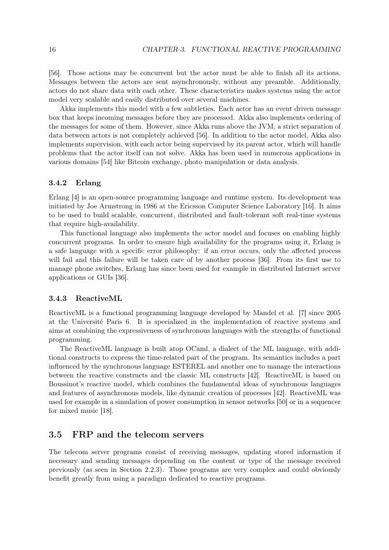
[56]. Those actions may be concurrent but the actor must be able to finish all its actions.Messages between the actors are sent asynchronously, without any preamble. Additionally,actors do not share data with each other. These characteristics makes systems using the actormodel very scalable and easily distributed over several machines.
Akka implements this model with a few subtleties. Each actor has an event driven messagebox that keeps incoming messages before they are processed. Akka also implements ordering ofthe messages for some of them. However, since Akka runs above the JVM, a strict separation ofdata between actors is not completely achieved [56]. In addition to the actor model, Akka alsoimplements supervision, with each actor being supervised by its parent actor, which will handleproblems that the actor itself can not solve. Akka has been used in numerous applications invarious domains [54] like Bitcoin exchange, photo manipulation or data analysis.
3.4.2 Erlang
Erlang [4] is an open-source programming language and runtime system. Its development wasinitiated by Joe Armstrong in 1986 at the Ericsson Computer Science Laboratory [16]. It aimsto be used to build scalable, concurrent, distributed and fault-tolerant soft real-time systemsthat require high-availability.
This functional language also implements the actor model and focuses on enabling highlyconcurrent programs. In order to ensure high availability for the programs using it, Erlang isa safe language with a specific error philosophy: if an error occurs, only the affected processwill fail and this failure will be taken care of by another process [36]. From its first use tomanage phone switches, Erlang has since been used for example in distributed Internet serverapplications or GUIs [36].
3.4.3 ReactiveML
ReactiveML is a functional programming language developed by Mandel et al. [7] since 2005at the Université Paris 6. It is specialized in the implementation of reactive systems andaims at combining the expressiveness of synchronous languages with the strengths of functionalprogramming.
The ReactiveML language is built atop OCaml, a dialect of the ML language, with addi-tional constructs to express the time-related part of the program. Its semantics includes a partinfluenced by the synchronous language ESTEREL and another one to manage the interactionsbetween the reactive constructs and the classic ML constructs [42]. ReactiveML is based onBoussinot’s reactive model, which combines the fundamental ideas of synchronous languagesand features of asynchronous models, like dynamic creation of processes [42]. ReactiveML wasused for example in a simulation of power consumption in sensor networks [50] or in a sequencerfor mixed music [18].
3.5 FRP and the telecom servers
The telecom server programs consist of receiving messages, updating stored information ifnecessary and sending messages depending on the content or type of the message receivedpreviously (as seen in Section 2.2.3). Those programs are very complex and could obviouslybenefit greatly from using a paradigm dedicated to reactive programs.
3.5. FRP AND THE TELECOM SERVERS 17
In this thesis, we will investigate one of the approaches to implement such programs, whichis the FRP paradigm. As we have seen in this chapter, this paradigm aims at abstracting awayall the pieces of code needed to handle events in traditional programming techniques. It claimsto produce clearer programs, which are also easier to reason about. In a nutshell, it appears tobe very promising for reducing the complexity of telecom servers applications.
However, the various problems (particularly those linked to memory and execution time)that have been spotted in various FRP implementations could prevent it for being concretelyusable in this kind of real-life application. As far as we know, the FRP paradigm has never beenused for this kind of large scale applications, being only used in research or basic programs1.
In the following chapters, we will select a FRP framework that will be used to develop aprototype simulating a LTE base station. We will then compare its performance and maintain-ability with another prototype that uses traditional programming techniques.
1Erlang is not considered here because despite being functional, telecom oriented and having been used forlarge applications, it is not using the semantics of the FRP paradigm and thus falls out of the thesis scope.

Chapter 4
Survey of the FRP frameworks
In this chapter, the approach used to select one framework for the prototype development willbe described and the outcome of the resulting survey will be presented.
4.1 Methodology
Having a good framework is important for the thesis work: it will make the comparison betweenthe two paradigms more relevant. Therefore, an investigation of the existing FRP frameworkswas performed in order to select one for the development of a LTE base station prototype.Indeed, more than twenty different FRP frameworks have been developed since FRP was cre-ated. However, they often target a specific application domain (like GUIs or music synthesis),which may not be adapted to a LTE base station prototype. Moreover, some of them arestill experimental and cannot be used for real applications. The survey was conducted in twophases: first a preliminary selection and then a final selection.
For the preliminary selection we considered only the FRP frameworks which were mentionedin the research papers discussed in Section 3.3. Each framework was studied with respect tothe following criteria:
• What language does the framework use? The different frameworks should indeed not usetoo many new languages in order to minimize the time spent learning them.
• Is the framework enough developed, stable and maintained? The framework should beusable to develop the prototype and it should be maintained, as a proof that it is not anabandoned project.
• Has the framework identified flaws? Frameworks with identified space and time leaksshould be avoided in order to have good performance in the prototype.
• For what kind of applications has this framework already been used? If the applicationdomain is similar to the thesis’ one, the framework is considered as a good candidate.
The complete list of the 21 frameworks that were investigated during this phase can befound in Appendix A.1.
At the end of the preliminary selection, four frameworks were selected. They are presentedin the next section. In order to make the final choice, a more detailed list of criteria was
18

4.2. PRESENTATION OF THE PRELIMINARY SELECTED FRAMEWORKS 19
elaborated. It can be found in Appendix A.2 and also contains brief explanations of why thecriteria are important. The different frameworks were studied more in detail so as to checkthese criteria. This included more literature and documentation studies but also some concreteexperimentation in order to determine if they were easy enough to use and to understand inthe limited time-frame of the thesis.
4.2 Presentation of the preliminary selected frameworks
The four selected frameworks (Scala.React, reactive-banana, Yampa and TimeFlies) are imple-mented in either Scala or Haskell. Haskell is a purely functional language, whereas Scala alsouses concepts from the object-oriented paradigm.
In order to have comparable examples of code, each framework has been used to implementa very simple currency converter which takes a price in euros (EUR) and converts it to Swedishcrowns (SEK). This example represents a typical reactive scenario: one value is updated bya user (here the price in EUR) and this automatically triggers the update of other relatedvalue(s) (here the price in SEK). Reacting to an external event and performing some actionsrelated to it are the core ideas used in the connection setup procedure. The implementationprocess of examples like the currency converter was used to investigate criteria such as the easeof understanding the framework and the support provided with it.
4.2.1 Scala.React
Scala.React [39] is a FRP library for Scala, which has been developed since 2010 at the EcolePolytechnique Fédérale de Lausanne by Ingo Maier and Martin Odersky (who is also the de-signer of the Scala language itself). The concepts of Scala.React and its implementation arepresented in [40]. In this report, it is explained why and how the observer pattern could bereplaced by reactive programming abstractions. Moreover, in [41], the authors present in detailone feature of Scala.React which improves the efficiency and the expressiveness of programs: ahigher-order functional reactive data structure. However, they also mention that there is roomfor optimization of the current implementation of Scala.React, which they are working with. InScala.React, the concept of behaviour is called signal. It is used to create dependencies betweenvariables. The changes are propagated using a push-based model [17].
The currency converter example can be implemented in Scala.React as follows:
Snippet 4.1: Currency converter example implemented in Scala.Reactval valueEUR = Signal{ NewAmount() }val valueSEK = Signal{ valueEUR() * 9.19} /*change value on the 29/07/2014*/
observe(valueEUR) {EUR =>//nicely print the value
}observe(valueSEK) {SEK =>//nicely print the value
}
In order to keep the example simple, we must assume that the signal NewAmount holds atany time the amount of money to be converted. The function Signal is used to create the

20 CHAPTER 4. SURVEY OF THE FRP FRAMEWORKS
depending signals valueEUR and valueSEK. The observe method contains a closure thatis invoked at every change of the signal value. In the example, the value will be printed againeach time there is a new amount of money to be converted.
4.2.2 Reactive-banana
Reactive-banana [6] is a FRP library for Haskell which is developed since 2011 by HeinrichApfelmus. The concepts and implementation of reactive-banana are described in a series ofarticles on the maintainer’s blog [14]. Reactive-banana implements the second version of theClassic FRP semantics [27], with some adjustments 1. Since reactive-banana follows the ClassicFRP semantics, it implements both behaviours and events.
The currency converter example can be implemented in reactive-banana as follows:
Snippet 4.2: Currency converter example implemented in reactive-bananaeValueEUR <- fromAddHandler newAmount
leteValueSEK :: Event t DoubleeValueSEK = (\euro -> euro * 9.19) <$> eValueEUR
reactimate $ printNicelyEUR <$> eValueEURreactimate $ printNicelySEK <$> eValueSEK
In this example, newAmount contains the updated value. This value is stored in the eventeValueEUR using the reactive-banana function fromAddHandler and the Haskell operator<-, which means "draw from". The <$> operator is used to apply the function on its left to thevalue of the event on its right. The $ operator is a Haskell operator used to avoid parenthesis.What is on its right takes precedence over what is on its left. Finally, the reactive-bananafunction reactimate is used to output results.
4.2.3 Yampa
Yampa [2] is a domain-specific embedded language in Haskell, which means that this languagebuilds abstractions dedicated to a specific domain (like animation, GUIs or networking). Ituses the concepts of FRP and is based on Fran. It is developed at Yale University by theYale Haskell Group2 since 2003. This group presented the Yampa language and its underlyingconcepts in detail in [32]. This article also contains an example of the use of Yampa for amobile robot. Robotics is not the only domain where Yampa has been used: in [25], the sameresearch group described an implementation of the game "Space Invaders" using it.
In order to diminish the risks of introducing space and time leaks into the systems developedwith it, Yampa is structured using arrows. Its abstractions for reactive behaviours are signalfunctions and events. Signal functions are a way of encapsulating time-varying values, but theyare first class functions so the programmer can directly manipulate them [17]. Additionally,Yampa provides a set of primitive combinators for event composition and a set of switching
1For example, it does not implement the switcher function and the continuous behaviours2http://haskell.cs.yale.edu/

4.2. PRESENTATION OF THE PRELIMINARY SELECTED FRAMEWORKS 21
combinators to enable the use of the dynamic dataflow structure. The changes are propagatedusing a pull-based model [17].
The example of the currency converter can be implemented in Yampa as follows:
Snippet 4.3: Currency converter example implemented in YampacurrencyConverter = proc -> do
valueEUR <- newAmountvalueSEK <- valueEUR * 9.19
returnA -< valueSEK
In the previous code snippet, currencyConverter is a signal function, defined using thekeyword proc. newAmount is a predefined signal function holding the updated value. Theconverted value is send as an input to returnA (the identity arrow, which plays the role ofthe return function in the arrow notation) using the arrow notation -<. The converted valueis returned each time the signal function is accessed.
4.2.4 TimeFlies
TimeFlies [11] is a FRP library for Haskell which was developed at the Rochester Instituteof Technology by Edward Amsden during his master thesis in 2013. Thus, the concepts andthe description how the framework was designed and implemented can be found in EdwardAmsden’s thesis [12]. The three main goals behind TimeFlies were to implement a frameworkthat has an efficient evaluation, a good composability of events and a simple integration withother Haskell libraries, like GUIs librairies.
TimeFlies uses the signal function abstraction. It also uses the concept of signal vectors inorder to be able to better control the inputs and outputs of the signal functions in a push-basedevaluation. According to its designer, it provides a semantic guarantee that no event will belost during evaluation. The language contains a whole set of combinators for manipulating thesignal functions. TimeFlies uses a push-pull evaluation model to propagate changes [12].
The currency converter example can be implemented in TimeFlies as follows:
Snippet 4.4: Currency converter example implemented in TimeFliescurrencyConverter :: SVEvent (Double) :~> SVEvent (IO())currencyConverter = pureEventTransformer convertAndPrint
whereconvertAndPrint :: Double -> IO()convertAndPrint valueEUR = do
let valueSEK = 9.19 * valueEURprintNicely valueEURprintNicely valueSEK
In order to keep the example concise, the setup code for the TimeFlies framework is notconsidered here. It is thus assumed that the value to be converted is to be handled by thefunction currencyConverter. The function pureEventTransformer will then applyconvertAndPrint to each new value of newAmount to obtain the result of the conversion.

22 CHAPTER 4. SURVEY OF THE FRP FRAMEWORKS
4.3 Result of the survey
After the further investigation of the preceding four FRP frameworks, the final selection wasmade: it was decided to use reactive-banana for developing the LTE base station prototype.
Implementing small examples like the currency converter enabled a deeper comparison ofthe syntax used by all frameworks. For instance, the Yampa example is the shortest one whereasthe Scala.React and the Timeflies examples are the longest ones. Secondly, all examples usespecific syntax elements and reactive-banana is the framework where the most specific syntaxelements were needed to write the example whereas Scala.React needed the least number ofspecific syntax elements. However, other aspects of the frameworks such as documentation,examples and help available were prioritized over syntactic sugar in the final choice of theframework to be used.
Indeed, the amount of documentation and help available for Scala.React was not sufficient tomanage the development of the prototype in the time-frame of the thesis work. Two additionalinsights about Scala.React were also obtained during this survey. First, as Scala.React usesScala, which mixes the object-oriented and the functional paradigm, it may not be the mostsuitable frameworks to emphasize the differences between FRP and traditional programmingtechniques like object-oriented programming. Secondly, even in the Scala.React enthusiastscommunity, there are some interactions on whether the framework is still under developmentand whether the released version is ready to be used in real-world projects [5].
Choosing a framework using Haskell as its host language was also motivated by the fact thatthere were experienced people available at Ericsson, which could help if something was goingwrong during the prototype development. At the time of the choice of the framework, Yampahad not been updated on Hackage since 2012 3. This is why TimeFlies was also investigated, asit was recent and closely related to Yampa (its aim was to improve Yampa’s performance andeffectiveness). However, TimeFlies has not sufficient amount of examples and documentationavailable, probably because it is a very recent framework. Last but not least, it uses a recentevolution of FRP which implements signal vectors. The new syntax introduced with thisevolution made the few examples available quite complicated to understand.
On the contrary to Yampa, reactive-banana is actively maintained and although its main-tainer has not published academic papers about his framework, he follows the semantics of thenew Classic FRP and discusses its implementation with Conal Elliott. Moreover, it is indicatedthat future development of reactive-banana will focus on performance, which is something im-portant for the prototype. Finally, given the limited experience of the author in FRP or telecomprogramming, the choice among the frameworks tested was somewhat arbitrary and affectedby the experienced ease and subjective judgement.
3But two updates were released later in 2014

Chapter 5
Prototype design and implementation
In this chapter, the approach that was used to define the reference model and to implementthe prototypes will be described. Details about the reference model and the implementationswill then be presented.
5.1 Methodology
In order to be able to determine whether the FRP paradigm leads to a less complex and moremaintainable implementation of the connection setup procedure, the initial approach was todevelop a prototype using FRP and to compare it to the code implementing the connectionsetup procedure in the real base station implementation. However, this approach had severaldownsides:
• Isolating the part of the implementation that would only deal with the connection setupprocedure would have been extremely time-consuming and maybe impossible. The basestation implementation is indeed very large and contains the code of numerous proceduresthat are sometimes interwoven with some others.
• The code extracted from the real implementation would not be executable without spend-ing a lot of time creating stubs for all the needed functions. Therefore, comparing theperformance of both implementation would imply relying on external tests that may bedifficult to have access to and/or not have been carried in relevant conditions for thisthesis.
• The prototype and the real implementation are not completely comparable programs.Indeed, they differ in some ways, such as:
– the complexity of the procedure. The real implementation realises the complete pro-cedure, including handling for various problems that can appear. Due to the limitedtime-frame allocated to the thesis work, it was not possible to implement a completeversion of the connection setup procedure in the prototype: only a simplified versionis implemented.
– the conditions of execution. Procedures in the real base station include real radio-signalling, which is not the case of the prototype: it will only be implemented on apersonal computer, for practical reasons. Therefore, comparing the performance ofthose two programs would be irrelevant.
23
24 CHAPTER 5. PROTOTYPE DESIGN AND IMPLEMENTATION
– how the code is written. The real implementation contains parts of code that areautomatically generated, which means that the programmer has no control over howthe paradigm is used in those parts. In the prototype, all the code will be writtenby hand. Such a difference could affect the maintainability comparison of the twopieces of code.
In order to perform a relevant comparison between the FRP paradigm and the traditionalparadigm that is used in the base station, both in terms of complexity and performance, it wasdecided to improve this approach: instead of only creating one FRP prototype, two prototypesimplementing the same design but using different paradigms will be developed. Thus, the onlysignificant difference between the implementations will be the paradigm they use and not some-thing else which cannot be controlled. The second prototype, which represents the traditionalprogramming techniques, will be implemented using the object-oriented programming languageC++, as it is the one used mostly in the real LTE base station implementation.
5.2 Reference model
The two prototypes will implement a simplified version of the connection setup procedure ina LTE base station (see Figure 2.4). This simplified version is our reference model. Thesimplifications made and the design decisions taken at the reference model level are presentedin the following subsections.
5.2.1 Simplified RRC connection setup procedure
The reactive behaviours which are investigated during this thesis are those typical of the telecomservers (mentioned in Section 3.5). Therefore, the simplified RRC connection setup procedurefocuses on two aspects: receiving/sending messages and modifying stored information if needed.Those two aspects are presented in the following subsections.
Messaging
The message sequence used in the reference model is almost the same as the one defined in theRRC standard [8] and is depicted in Figure 2.4 for a successful connection. Apart from thiscase of the success of the procedure, the reference model also contains three scenarios wherethe connection setup procedure fails and the UE is not attached. A UE is rejected if:
• the eNodeB rejects its RRC connection request.
• the security mode fails to complete. This happens if the decryption of the security modecommand message failed.
• the RRC connection reconfiguration fails to complete.
The sequence diagrams for those three scenarios can be found in Appendix B.
The content of the messages exchanged during all possible scenarios are most of the timesimplified, in order to only keep the pieces of information that are needed for modifying thestored information or for sending the response. The other pieces of information, for examplethose needed by other procedures or for configuring the radio signalling, were discarded. The
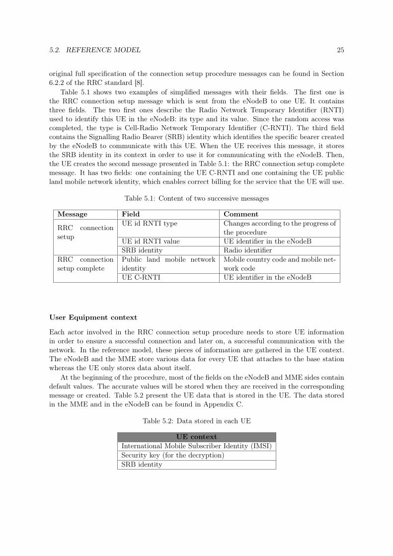
5.2. REFERENCE MODEL 25
original full specification of the connection setup procedure messages can be found in Section6.2.2 of the RRC standard [8].
Table 5.1 shows two examples of simplified messages with their fields. The first one isthe RRC connection setup message which is sent from the eNodeB to one UE. It containsthree fields. The two first ones describe the Radio Network Temporary Identifier (RNTI)used to identify this UE in the eNodeB: its type and its value. Since the random access wascompleted, the type is Cell-Radio Network Temporary Identifier (C-RNTI). The third fieldcontains the Signalling Radio Bearer (SRB) identity which identifies the specific bearer createdby the eNodeB to communicate with this UE. When the UE receives this message, it storesthe SRB identity in its context in order to use it for communicating with the eNodeB. Then,the UE creates the second message presented in Table 5.1: the RRC connection setup completemessage. It has two fields: one containing the UE C-RNTI and one containing the UE publicland mobile network identity, which enables correct billing for the service that the UE will use.
Table 5.1: Content of two successive messages
Message Field Comment
RRC connectionsetup
UE id RNTI type Changes according to the progress ofthe procedure
UE id RNTI value UE identifier in the eNodeBSRB identity Radio identifier
RRC connectionsetup complete
Public land mobile networkidentity
Mobile country code and mobile net-work code
UE C-RNTI UE identifier in the eNodeB
User Equipment context
Each actor involved in the RRC connection setup procedure needs to store UE informationin order to ensure a successful connection and later on, a successful communication with thenetwork. In the reference model, these pieces of information are gathered in the UE context.The eNodeB and the MME store various data for every UE that attaches to the base stationwhereas the UE only stores data about itself.
At the beginning of the procedure, most of the fields on the eNodeB and MME sides containdefault values. The accurate values will be stored when they are received in the correspondingmessage or created. Table 5.2 present the UE data that is stored in the UE. The data storedin the MME and in the eNodeB can be found in Appendix C.
Table 5.2: Data stored in each UE
UE contextInternational Mobile Subscriber Identity (IMSI)Security key (for the decryption)SRB identity

26 CHAPTER 5. PROTOTYPE DESIGN AND IMPLEMENTATION
Figure 5.1: Overview of the reference model
5.2.2 System architecture
Figure 5.1 presents an overview of the system architecture for the reference model.A prototype consists of three components, which implement the three types of actors in-
volved in the connection setup procedure: the MME, the eNodeB and the UEs. There arealways one MME and one eNodeB, whereas the number of UEs can vary. However, all the UEsare within the same UE component.
The messages exchanged between the three components are of two types: RRC messages(for communication between the UE and the eNodeB) or S1 messages (for communicationbetween the eNodeB and the MME). The messages implement the different fields defined inthe simplified RRC connection setup procedure. The various identifiers used in the differentmessages are either derived from the UE number (attributed when it is created) for the UEidentifiers or generated randomly for the other identifiers.
A prototype also contains logging tools which register the content of each message arriving inone of the three components. Information about the number of messages received is registeredin the eNodeB and MME logs. The log for the UE component indicates how many UEs werepowered on. When a UE completes the procedure in one component (either with success orfail) a specific log entry is printed. Each log entry has a timestamp and there is one log filecreated for each of the three components.
5.2.3 Deployment details
The three components run in the same Linux computer and they communicate with each otherusing the Transmission Control Protocol (TCP) protocol (which is similar to the real-timesignalling used in the real base station), as depicted in Figure 5.2. Since the programs arerunning in the same computer for practical reasons, another simplification was made: theprototypes are not handling packet loss in the network. Moreover, every component runs inone operating system thread, including the UE component (meaning that all the UEs are inthe same thread).

5.3. IMPLEMENTATIONS 27
Figure 5.2: Deployment view of the reference model
5.2.4 Simulation parameters
In order to be as close to the real situation as possible, some RRC connection setup proceduresmust fail to complete, according to the scenarios described in 5.2.1. Therefore, two failuremodes were implemented.
The first failure scenario occurs after the RRC connection request message. In the referencemodel, 3% of the UEs are rejected at this stage. The second failure scenario occurs if the securitymode is not completed. It was chosen not to implement a failure mode for this scenario in theprototypes. The last failure scenario occurs if the RRC connection reconfiguration fails. In thereference model, 1% of the UEs which initiated the reconfiguration are rejected at this stage.
5.3 Implementations
The complete source code of both prototypes is available online1. In this Section, the particu-larities of each implementation will be presented.
5.3.1 FRP implementation
The FRP implementation of the LTE base station prototype is coded in Haskell using thereactive-banana framework. It is structured using the Haskell Cabal2, which is a system en-abling the use of a common architecture for building Haskell applications and libraries.
Program design
In order to implement the reference model using FRP, the three main components were split insmaller design modules (depicted as light blue boxes in Figure 5.3). The arrows indicate that amodule uses function(s) from another module. Each design module is implemented using oneor several Haskell modules (depicted as dark blue boxes in Figure 5.3). Using Haskell modulesis the way used to structure programs in Haskell. Each Haskell module corresponds to onesource code file with the same name (except from the main modules which must be named"main", whatever the name of the source code file).
1https://github.com/Ilydocus2http://www.haskell.org/cabal/

28 CHAPTER 5. PROTOTYPE DESIGN AND IMPLEMENTATION
The design modules are organized as follows. First, there are three main modules whichcontain the main functions of each three components (i.e. all the FRP setup and the messagehandling logic). Then there are six other modules which contain functions that are used inat least two of the main modules. These functions belong to different areas. The functionsthat are found in the logging module (implemented in the Haskell module LogTools) handleall the logging-related actions of the prototype. Then, the FRP module contains FRP setupfunctions used by all three components. The random identifiers generation module containsthe functions used to generate randomly the different fields of the UE context. The UE contextmodule contains the definition of the three different UE context, as well as the functions used tomodify or print those contexts. Finally the messages modules contains the message definitionsand the functions related to them. It is implemented using two Haskell modules, one for eachtype of messages (RRC or S1).
Figure 5.3: Module coupling in the FRP prototype
The following subsections present the interesting particularities of the FRP prototype im-plementation. This includes a description of how the handling of a message is performed in thisprototype, focusing on the important parts for the telecom servers: receiving/sending messagesand modifying stored information when needed. The same description will also be made forthe OOP prototype in order to be able to compare both implementations.
Haskell light-weight threads
Even if each of the three programs runs in one operating system thread, some parts of theprograms need to use concurrency, i.e. to execute different actions at the same time. Forexample, the UE program has to implement several UEs that will simultaneously try to attachto the base station.
In the FRP prototype, concurrency is achieved using Haskell light-weight threads. This kindof thread can be created using the function forkIO, which belongs to Concurrent Haskell [35].They are called light-weight because both thread creation and context switching overheads arevery low. They are thus very cheap to use and more efficient than operating system threads.

5.3. IMPLEMENTATIONS 29
The scheduling of those threads is done internally by the Haskell runtime system. Haskellthreads are non-deterministic, meaning that the order in which they will execute cannot bespecified.
Snippet 5.1 shows how the different UEs are created and powered on simultaneously in theprototype:
Snippet 5.1: Creating and powering up several UEsues <- mapM (async . powerOn logh) [1..nbOfUes]mapM_ wait ues
Here the function async is used. It is part of a Haskell module which is a thin layer over thebasic concurrency operations providing functions for performing I/O operations asynchronouslyand waiting for their results.
Setting up the event network
The reactive-banana framework uses an event network to implement FRP. This event networkcontains the event logic of the program: what type of events the event network will handleand how to react to them. Implementing the event network means describing these events andreactions in a function in the source code. The event network can execute actions outside ofitself using a specific instruction.
Snippet 5.2 shows the main function of the eNodeB program. It presents how the eventnetwork is set up. We can see that the setup of an FRP network (with the data structureneeded to store the UE contexts and a log system) does not demand a lot of code: only 6lines. Moreover, since FRP provides high-level abstractions for the setup, it is concise and thedifferent parts are rather easy to understand.
Snippet 5.2: Set up of the event networkmain :: IO ()main = dosources <- makeSourcesenbMap <- newTVarIO Map.emptylogh <- openFile "log_enb.txt" WriteModenetwork <- compile $ setupNetwork sources (return enbMap) loghactuate networkeventLoop sources
The function eventLoop receives the messages sent to the eNodeB using the TCP protocoland fires the corresponding events to the event network in order for them to be handled.
Receiving a message and reacting to it
As explained in the previous paragraph, the messages are received in the eventLoop functionand fired to the event network as soon as they are received. Snippet 5.3 shows how the messagescoming from the UEs are received, decoded and then sent to the event network in the eNodeB.Thanks to the high-level abstractions of both Haskell and FRP, this takes only two lines ofcode: one for receiving and decoding the message and one for sending it to the event network.Those lines do not contain any byte operation. We can also notice that the FRP prototype

30 CHAPTER 5. PROTOTYPE DESIGN AND IMPLEMENTATION
does not discriminate the different messages arriving from the UEs before sending them to theevent network. It does however separate the messages coming from the UEs and from the MME(since they arrive on different sockets and have different types) but both will be handled in thesame event network.
Snippet 5.3: Message reception decoding and sending to the event networkmessDecUe <- decode <$> recv ueSock 1024(fire messageUe (messDecUe,ueSock,mmeSock))
Once the message arrives in the event network, it will be handled according to its type. Inorder to understand how a message is handled in the FRP prototype, we take the example ofan incoming RRC Connection Request message.
Snippet 5.4 contains the parts of the event network function that are related to the handlingof this message. The handling of an event is composed of different steps:
1. The event is retrieved from the event source (line 4)
2. Depending on the type of message which arrived, a specific event is created, hereeRrcConnectionRequest (line 24)
3. When the eRrcConnectionRequest event is fired, the createRrcCS function isexecuted (line 29). This function creates a new event containing the response message,which is either RRC Connection Reject or RRC Connection Setup, depending on theC-RNTI contained in the event eRrcConnectionRequest.
4. Different response messages are aggregated in the event (line 41) eResponseMessage,including eResponseRrrcCRequest created during the previous step.
Different outputs are also defined in the function describing the event network:
• the received message (contained in the event eMessageUe) is written to the log file (line49).
• the IMSI identifier contained in the received message (once it is identified as an RRCconnection request) is added to the UE context corresponding to the sending UE (line47).
• the response message (contained in the aggregated event eResponseMessage) is sentto the UE (line 45).
Snippet 5.4: Handling of the RRC Connection Request message1 setupNetwork :: forall t. Frameworks t =>2 (EventSource (RrcMessage,Socket,Socket), EventSource(S1ApMessage,
Socket,Socket))-> IO(TVar EnbMap) -> Handle -> Moment t ()3 setupNetwork (messageUe, messageMme) state logh = do4 eMessageUe <- fromAddHandler (addHandler messageUe)5 --(...)6 let7 --(...)8 --Behavior holding the state
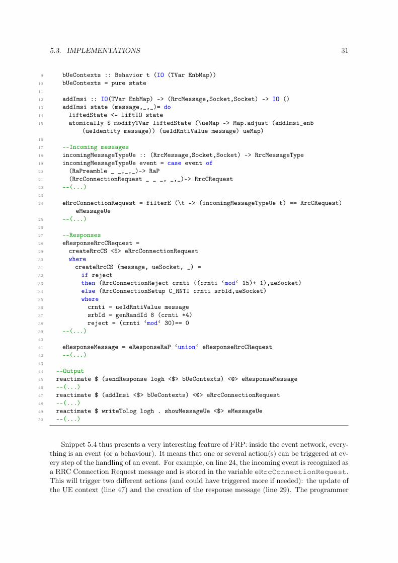
5.3. IMPLEMENTATIONS 31
9 bUeContexts :: Behavior t (IO (TVar EnbMap))10 bUeContexts = pure state11
12 addImsi :: IO(TVar EnbMap) -> (RrcMessage,Socket,Socket) -> IO ()13 addImsi state (message,_,_)= do14 liftedState <- liftIO state15 atomically $ modifyTVar liftedState (\ueMap -> Map.adjust (addImsi_enb
(ueIdentity message)) (ueIdRntiValue message) ueMap)16
17 --Incoming messages18 incomingMessageTypeUe :: (RrcMessage,Socket,Socket) -> RrcMessageType19 incomingMessageTypeUe event = case event of20 (RaPreamble _ _,_,_)-> RaP21 (RrcConnectionRequest _ _ _, _,_)-> RrcCRequest22 --(...)23
24 eRrcConnectionRequest = filterE (\t -> (incomingMessageTypeUe t) == RrcCRequest)eMessageUe
25 --(...)26
27 --Responses28 eResponseRrcCRequest =29 createRrcCS <$> eRrcConnectionRequest30 where31 createRrcCS (message, ueSocket, _) =32 if reject33 then (RrcConnectionReject crnti ((crnti ‘mod‘ 15)+ 1),ueSocket)34 else (RrcConnectionSetup C_RNTI crnti srbId,ueSocket)35 where36 crnti = ueIdRntiValue message37 srbId = genRandId 8 (crnti *4)38 reject = (crnti ‘mod‘ 30)== 039 --(...)40
41 eResponseMessage = eResponseRaP ‘union‘ eResponseRrcCRequest42 --(...)43
44 --Output45 reactimate $ (sendResponse logh <$> bUeContexts) <@> eResponseMessage46 --(...)47 reactimate $ (addImsi <$> bUeContexts) <@> eRrcConnectionRequest48 --(...)49 reactimate $ writeToLog logh . showMessageUe <$> eMessageUe50 --(...)
Snippet 5.4 thus presents a very interesting feature of FRP: inside the event network, every-thing is an event (or a behaviour). It means that one or several action(s) can be triggered at ev-ery step of the handling of an event. For example, on line 24, the incoming event is recognized asa RRC Connection Request message and is stored in the variable eRrcConnectionRequest.This will trigger two different actions (and could have triggered more if needed): the update ofthe UE context (line 47) and the creation of the response message (line 29). The programmer

32 CHAPTER 5. PROTOTYPE DESIGN AND IMPLEMENTATION
does not have to take care of the order in which those actions will be performed: both willbe performed when the event is fired. Other features from Haskell and FRP are also presentin Snippet 5.4: pattern matching, event filter and event union. Pattern matching is found inseveral functional programming languages (including Haskell). On line 20 and 21, it enables aquick filtering of the messages. There is no need to have an additional attribute to discriminatewhich message it is, only the type of the message is enough. The filtering function is thus keptvery brief and easy to read. Event filter is a FRP feature. On line 24, it enables a specific eventto be fired only when a certain message is received. It is thus possible to create different subevents all deriving from the same main event. The reverse operation is event union and is usedon line 41. This enables the responses to be sent using only one line for all similar messages.Finally, we can notice that creating a response message is very concise, as it takes only one lineof code (line 33 for example).
Updating the User Equipment context
The eNodeB and the MME need to store the UE context of several UEs whereas each UE onlystores its own information. The UE context is stored in a record which needs to be updatedseveral times during the RRC connection setup procedure.
However, since having a variable that is mutable is not in the spirit of functional program-ming, it was needed to use a specific type of variable: a transactional variable (TVar). Thosevariables can be modified using specific primitives (such as modifyTVar). In order to avoidconcurrency problems, all the modifications or accesses to the TVar variables are performedatomically.
Encoding
In order to be sent to the TCP network, the messages (which are values of custom algebraicdata types) need to be encoded into byte strings. This is done in the FRP prototype by usingthe Put and Get monads. Each message is encoded by creating a byte string that contains twoparts: first a number which indicates what type of message it is and then the different fields ofthe message. The details of the message encoding and decoding can be found in the modulesRrcMessages and S1Messages, which were developed during the thesis but are not included inthis report.
Encryption
The message Security Mode Command (see Figure 2.4) contains a field which is encrypted.The UE which receives this message needs to decrypt it and compare it to its reference value inorder to imitate (on a smaller scale) the encryption process which takes place in the real basestation implementation. In the FRP prototype, this encryption and decryption is performedusing the Haskell package AES3.
5.3.2 OOP implementation
The second prototype, which represents the traditional programming techniques, is imple-mented using the object-oriented programming paradigm and the language C++.
3http://hackage.haskell.org/package/AES

5.3. IMPLEMENTATIONS 33
Program design
The class diagram presenting how the reference model is implemented in the OOP prototypecan be found in Figure 5.4.
Figure 5.4: Class diagram of the OOP prototype
The main function for each component creates an event handler. The event handler powersup the UEs (in the UE program) and receives the different messages. The handling of thosemessages is the task of an appropriate UeContext. There is one UeContext per UE in each ofthe three components and it also contains the UE context for this UE.
The following subsections present the interesting particularities of the OOP prototype im-plementation. This includes a description of how the different steps of the handling of a messageare performed in this prototype and a comparison with how the FRP prototype performs them.
Handling of events
There is no equivalent in C++ to the Haskell light-weight threads. Therefore, another approachwas used to enable the concurrent treatment of different messages: the use of the epoll facility.This facility regroups three Linux kernel system calls which provide I/O event notifications.It uses a file descriptor (created using epoll_create) which registers interest for other filedescriptors (registration is done using epoll_ctl). The epoll instance then waits (usingepoll_wait) for an event to occur in one of the registered file descriptors. Snippet 5.5 showsan example of a set up of the epoll instance (from the file EnbEventHandler.cc). The epollinstance is first created (line 5), then the socket that is used to communicate with the MMEis added to the file descriptor of the instance in order for it to receive a notification when anew message arrives on this socket (line 14). Finally, the epoll instance waits in an infiniteloop until an event arrives in one of its registered file descriptors (line 22). The code whichfollows this line will handle the incoming event. In the prototype, the epoll function is usedin edge-triggered mode on the receiving sockets, which means that epoll_wait will returnonly when a new message is detected on those sockets.
Snippet 5.5: Partial set up of the epoll instance1 void EnbEventHandler::run () {2 epoll_event ev, events[MAX_EVENTS];3 int connSock, nfds, epollfd;4
34 CHAPTER 5. PROTOTYPE DESIGN AND IMPLEMENTATION
5 epollfd = epoll_create(MAX_EVENTS);6 if (epollfd == -1) {7 std::cerr << "error in epoll_create" << std::endl;8 exit(EXIT_FAILURE);9 }
10 //(...)11
12 ev.events = EPOLLIN | EPOLLET;13 ev.data.fd = mMmeSocket;14 if (epoll_ctl(epollfd, EPOLL_CTL_ADD, mMmeSocket, &ev) == -1) {15 std::cerr << "error in epoll_ctl: mMmeSocket" << std::endl;16 exit(EXIT_FAILURE);17 }18 //(...)19
20 for (;;) {21
22 nfds = epoll_wait(epollfd, events, MAX_EVENTS, -1);
Snippet 5.5 illustrates well the differences between the FRP and the OOP prototypes whenit comes to setting up the handling of events (which is a very important part in the telecomservers). First, the number of lines needed for the setup is higher in the OOP prototype.Then, the abstractions used in the OOP prototype are on a much lower level. This has severalimplications: first the programmer needs more time to understand how the setup works, then heor she also has to read up on the different options to be sure that the epoll instance is correctlyconfigured and finally because of the previous aspects, it is easier to make mistakes, hence thedifferent error handlers that are in the snippet. During the prototypes’ implementation, it wasmore time-consuming to setup the epoll instance than the FRP event network. However, theepoll instance allows more configuration options, as it is on a lower level of abstraction.
Receiving a message and reacting to it
As it was stated in the previous paragraph, when an event occurs on a registered file descriptor,the function epoll_wait returns. If this event corresponds to a message arriving from aUE which is currently performing the RRC connection setup procedure, the following code isexecuted:
Snippet 5.6: Reception, decoding and handling beginning of one UE message1 ssize_t bytesReceived;2 char incomingDataBuffer[1000];3 memset(incomingDataBuffer,0,1000);4 bytesReceived = recv(events[n].data.fd, incomingDataBuffer,1000, 0);5 if (bytesReceived == 0) {std::cout << "host shut down." << std::endl;}6 if (bytesReceived == -1){std::cerr << "recieve error!" << std::endl;}7 if (bytesReceived != -1 && bytesReceived != 0){8 incomingDataBuffer[bytesReceived] = ’\0’;9 GOOGLE_PROTOBUF_VERIFY_VERSION;
10 std::string strMessage(incomingDataBuffer, bytesReceived);11 RrcMessage rrcMessage;12 rrcMessage.ParseFromString(strMessage);
5.3. IMPLEMENTATIONS 35
13
14 UeMapUe::iterator tempIt = mUeContextsUe.find(events[n].data.fd);15 UeContextEnb *ueContext = tempIt->second;16 handleUeMessage(rrcMessage, ueContext);
Snippet 5.6 implements one of the important reactive behaviours for the telecom servers:the reception of a message. The higher abstraction level of the FRP paradigm can also beseen when comparing this snippet to Snippet 5.3. Instead of the two elegant lines of the FRPprototype, the OOP prototype needs 15 lines which include very low level actions, such as online 8, were the "end of string" character needs to be manually added to the received message.
At the end of Snippet 5.6, the message is received (line 4), decoded (line 12) and theUeContext object corresponding to the relevant UE has been found (line 14 and 15). In thehandleUeMessage function (line 16), each message will be handle according to its type. Wetake the example of the reception and handling of a RRC Connection Request message.
Snippet 5.7 shows the part of handleUeMessage related to this message. This snippetshows the OOP equivalent to the pattern matching of the FRP prototype. Here the RRCmessage needs to carry a specific attribute to indicate which messages it carries. Then the realmessage needs to be retrieved in a variable in order to be able to call the right handler. This ismore low level and less readable than the pattern matching performed in the FRP prototype.
Snippet 5.7: Extract of the handleUeMessage function1 void EnbEventHandler::handleUeMessage(RrcMessage rrcMessage, UeContextEnb
*ueContext){2 //(...)3 switch (rrcMessage.messagetype()){4 //(...)5 case RrcMessage_MessageType_TypeRrcCRequest :6 {RrcConnectionRequest rrcCRequest;7 rrcCRequest = rrcMessage.messagerrccrequest();8 ueContext->handleRrcConnectionRequest(rrcCRequest);}9 break;
10 //(...)11 default:12 std::cerr << "Unexpected message type from Ue in eNodeB" << std::endl;13 }14 }
The next part of the code related to the handling of this message is found in the file UeCon-textEnb.cc (see Snippet 5.8). It consists of the function handleRrcConnectionRequest,called on line 8 in Snippet 5.7.
Snippet 5.8: Function handleRrcConnectionRequest
1 void UeContextEnb::handleRrcConnectionRequest(RrcConnectionRequest message){2
3 std::ostringstream messageLog;4 messageLog << "Message received from Ue: RrcConnectionRequest {Rnti Type: " <<
message.ueidrntitype() << " Rnti Value: " << message.ueidrntivalue() << " UEidentity is : " << (message.ueidentity()).mcc()<<"-"<<(message.ueidentity()).mnc() << "-"<< (message.ueidentity()).msin() <<" }" <<

36 CHAPTER 5. PROTOTYPE DESIGN AND IMPLEMENTATION
std::endl;5 mLog->writeToLog(messageLog.str());6
7 mState->imsi = message.ueidentity();8
9 RrcMessage rrcMessage;10 bool reject;11 reject = (message.ueidrntivalue() % 30) == 0;12 if (reject) {13 RrcConnectionReject *rrcCReject = new RrcConnectionReject;14 rrcCReject->set_uecrnti(message.ueidrntivalue());15 rrcCReject->set_waitingtime((message.ueidrntivalue() % 15)+1);16
17 rrcMessage.set_messagetype(RrcMessage_MessageType_TypeRrcCReject);18 rrcMessage.set_allocated_messagerrccreject(rrcCReject);19 printState();20 }21 else {22 std::string * srbId = new std::string;23 genRandId(srbId, 8);24 mState->srbIdentity = *srbId;25 delete srbId;26
27 RrcConnectionSetup *rrcCS = new RrcConnectionSetup;28 rrcCS->set_ueidrntitype(C_RNTI);29 rrcCS->set_ueidrntivalue(message.ueidrntivalue());30 rrcCS->set_srbidentity(mState->srbIdentity);31
32 rrcMessage.set_messagetype(RrcMessage_MessageType_TypeRrcCS);33 rrcMessage.set_allocated_messagerrccs(rrcCS);34 }35
36 sendRrcMessage(mUeSocket,rrcMessage);37 }
Snippet 5.8 shows the different steps of the handling of the RRC connection request:
1. The UE context is updated according to the C-RNTI of the received message (line 7).
2. Depending on whether the request is rejected or not, the response message is created(lines 13-18 or 27-33).
3. If the request is accepted, the SRB id is added to the UE context (line 24).
4. Finally, the response message is sent (line 36).
This snippet shows important differences between the prototypes on aspects related to theimportant reactive behaviours in the telecom servers. First creating the response messagetakes 5 or 6 lines (depending on the number of fields in the message) in the OOP prototypewhereas it takes 1 line in the FRP prototype. Moreover, the logging instructions, the storingof the IMSI instructions, the creation of the response message and the sending of the responseare in every message handler in the OOP prototype. In the FRP prototype, those parts are

5.3. IMPLEMENTATIONS 37
more clearly separated and common code is only written once in the event network function.However, the storing of the IMSI is more straightforward in the OOP prototype and requires 1line. In the FRP prototype, it requires an additional function and 5 lines in total. Moreover, asstoring a value in a data structure which can be modified is not really in the spirit of functionalprogramming, it requires the use of the specific type of variable TVar which demands a bit oflearning to handle.
Updating the User Equipment context
In the C++ implementation of the prototype, the UE context is contained in a data structure.The relevant UeContext object (UeContextUe, UeContextEnb or UeContextMme) which rep-resents the UE has a pointer to this structure in its attributes. Updating the UE context isthus done by using this pointer.
Encoding
The message encoding in the C++ implementation is taken care of by the Google ProtocolBuffers Application Programming Interface (API)4. The structure of all the messages is declaredusing a specific language in separate files. Then, these files are used by the API to generateC++ files which contain all the functions needed to encode/decode and use the messages.
Encryption
In the C++ prototype, the encryption and decryption of the Security Mode Command fieldare performed using the Crypto++ library5.
4https://developers.google.com/protocol-buffers/5http://www.cryptopp.com/

Chapter 6
Performance evaluation
In this chapter, the performance evaluation part of the thesis work will be presented. Theaim of this part was to investigate the first aspect of the thesis’ hypothesis: Using FunctionalReactive Programming as a programming model leads to a suitably performing programcompared to the current implementation of the RRC protocol in a LTE base station.
6.1 Key performance indicators
The performance of both prototypes is going to be evaluated according to different key perfor-mance indicators. The indicators used were thus:
• time needed for the three components to attach X UEs (where X is a placeholder for afixed number which can take different values)
• time needed for the UE component to attach for each UE
• memory footprint of each of the three programs
• CPU footprint of each of the three programs
Those indicators were selected because they are the ones which are of interest in the realbase station implementation.
6.2 Methodology
In order to carry out the performance evaluation and to measure the different key performanceindicators, several tests were done using both prototypes. The following sections present thetests which were performed and how they were performed.
6.2.1 Testing environment
All the tests presented in this chapter were performed on the same test machine, which isequivalent in terms of hardware and operating system to what is used in the real base station.This test machine is a Dell Inspiron 7537 laptop which is running Ubuntu 14.04 LTS 64-bit. This computer is equipped of a Intel Core i7-4500U Haswell CPU and of 8Gb of DDR3
38
6.3. RESULTS 39
Random-Access Memory (RAM). The programs where compiled using the version 4.8.1 of theGNU Compiler Collection (GCC) (for the OOP prototype) and the version 7.6.3 of the GlasgowHaskell Compiler (GHC) (for the FRP prototype).
6.2.2 Testing procedure
Performing a test consists in executing the three programs (UE, eNodeB and MME) whichcompose each prototype. The CPU usage, the memory usage and other statistics are measuredfor each program using the Linux commands top and pidstat. In addition, for the FRPprototype programs, the Haskell runtime system is used to obtain additional information, liketime spent in garbage collection. Time information for the execution of the UEs is obtainedwith the help of specific lines of the log files which are generated during the execution of theprograms. Each test is executed automatically several times (five times for each of the tenfixed numbers of UEs in Scenario 1 and three times in Scenario 2 below) with the help of bashscripts.
6.2.3 Testing scenarios
Two different scenarios were thus investigated to evaluate the performance of both prototypes.They simulate different situations which the base station encounters during its use.
Scenario 1: A fixed number of UEs is powered on
In this scenario, the UE program is asked to power on a fixed number of UEs. Those UEs arepowered on in a limited amount of time, resulting in a bursty behaviour. This scenario thuscorresponds to a peak load test. Such a situation, where a large number of UEs will try toconnect to the base station almost simultaneously corresponds for example to a train enteringthe base station area when moving or to the end of a movie, where all the users begin to usetheir smartphones again.
Scenario 2: A random number of UEs is powered on each second
However, most of the time, the base station is not experiencing a bursty behaviour. Therefore,it was also important to test the behaviour of both prototypes in a scenario which simulatesa spread load. In this second scenario, the UE program was slightly modified to power on arandom number of UEs every second, those random numbers being Poisson distributed.
6.3 Results
The two preceding scenarios were thus implemented and tested. The results of those tests arepresented in this section.
In the prototypes, the total time to power on a given number of UEs is calculated from thebeginning of the program execution until the moment where all UEs have completed the RRCconnection setup procedure, either with success or not. However, when the average time for oneUE to attach is presented, only the successful ones are taken into account (those which receivedthe RRC connection accept message), as the rejected ones do not have to send and receive thesame amount of messages. The proportion of rejected UEs were defined in the reference model(see Section 5.2.4).
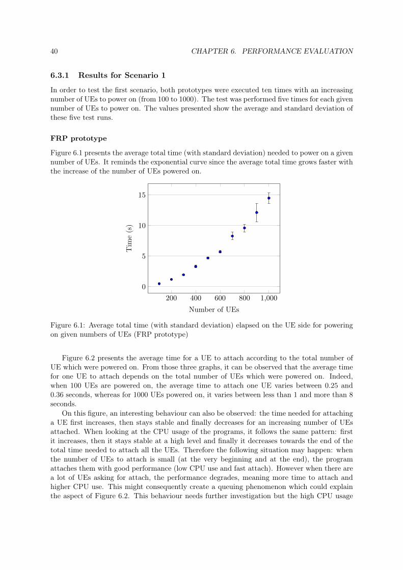
40 CHAPTER 6. PERFORMANCE EVALUATION
6.3.1 Results for Scenario 1
In order to test the first scenario, both prototypes were executed ten times with an increasingnumber of UEs to power on (from 100 to 1000). The test was performed five times for each givennumber of UEs to power on. The values presented show the average and standard deviation ofthese five test runs.
FRP prototype
Figure 6.1 presents the average total time (with standard deviation) needed to power on a givennumber of UEs. It reminds the exponential curve since the average total time grows faster withthe increase of the number of UEs powered on.
200 400 600 800 1,000
0
5
10
15
Number of UEs
Tim
e(s
)
Figure 6.1: Average total time (with standard deviation) elapsed on the UE side for poweringon given numbers of UEs (FRP prototype)
Figure 6.2 presents the average time for a UE to attach according to the total number ofUE which were powered on. From those three graphs, it can be observed that the average timefor one UE to attach depends on the total number of UEs which were powered on. Indeed,when 100 UEs are powered on, the average time to attach one UE varies between 0.25 and0.36 seconds, whereas for 1000 UEs powered on, it varies between less than 1 and more than 8seconds.
On this figure, an interesting behaviour can also be observed: the time needed for attachinga UE first increases, then stays stable and finally decreases for an increasing number of UEsattached. When looking at the CPU usage of the programs, it follows the same pattern: firstit increases, then it stays stable at a high level and finally it decreases towards the end of thetotal time needed to attach all the UEs. Therefore the following situation may happen: whenthe number of UEs to attach is small (at the very beginning and at the end), the programattaches them with good performance (low CPU use and fast attach). However when there area lot of UEs asking for attach, the performance degrades, meaning more time to attach andhigher CPU use. This might consequently create a queuing phenomenon which could explainthe aspect of Figure 6.2. This behaviour needs further investigation but the high CPU usage

6.3. RESULTS 41
may be caused by a part of the reactive-banana implementation which has been identified byits maintainer as decreasing the framework performance [15].
0 50 100
0.2
0.3
0.4
UE attaching order
Tim
e(s
)
0 200 400
0
2
4
UE attaching order0 500 1,000
0
5
10
UE attaching order
Figure 6.2: Average time (with standard deviation) elapsed on the UE side for attaching a UEin the FRP prototype for 100, 500 and 1000 UEs powered on
Moreover, a problem appeared during the testing: the productivity of the UE program wasa lot lower than the productivity of the eNodeB and MME programs. The productivity,which is calculated by the Haskell runtime system, is the percentage of execution time spentdoing productive work (i.e. not spent doing garbage collection). A low productivity thereforeindicates that the program spends a lot of time in garbage collection, meaning that the programgenerates a lot of heap allocated data. A satisfactory productivity is above 90% [45].
Figure 6.3 shows clearly that the UE program has a much lower productivity than theeNodeB and the MME programs. The only noticeable difference between the UE program andthe other ones is that several FRP event networks are concurrently created and used in theUE program whereas the eNodeB and the MME use only one FRP event network each. Thissuggests that creating a lot of FRP event networks using Haskell’s concurrency does not resultin good performance.
Since the UE program was experiencing performance troubles which could affect the eN-odeB program, it was decided to develop a second version of this program (with the samemessaging sequence and actions on the messages) which would not use FRP but classic func-tional programming. It means that we don’t use an FRP event network anymore to handle themessaging. Instead, the messages are received and treated in a sequential order. By doing so,we loose the flexible event handling system of FRP but we hope to solve the performance issue.Scenario 1 was then conducted again using this second version of the program.
First, Figure 6.4 shows that the productivity of the UE program using classic functionalprogramming is now comparable to the productivity of the eNodeB and MME programs usingFRP. Then, the average total time elapsed for a given number of UEs to complete the RRCconnection setup procedure is presented in Figure 6.5. Two interesting conclusions can bedrawn from this graph:
• The average total time is around five times lower than when using the FRP UE program(see Figure 6.1).

42 CHAPTER 6. PERFORMANCE EVALUATION
100 500 1000
20
40
60
80
100
65
32
20
9691
86
98 9589
Pro
duct
ivity
(%)
UE eNodeB MME
Figure 6.3: Average productivity (with standard deviation) of the FRP prototype programsaccording to the number of UEs powered on
• The average total time is now increasing close to linearly with the number of poweredon UEs. However, there are some outliers (it is particularly visible for 700, 900 and 1000UEs) which are also the values with the highest standard deviation.
During those tests, another interesting behaviour occured: when testing the prototype with500 UEs or more, a minority of test runs (on average 1.5 with a standard deviation of 0.76)would not complete in an reasonable amount of time (indicating a potential deadlock situation)and are thus not included in the values presented in the graphs. This may explain the outliersobserved on Figure 6.5. It also suggests that this configuration of the FRP prototype (with aclassic functional UE program and a FRP eNodeB and MME programs) is not always reliablewhen more than 500 UEs simultaneously try to attach. This behaviour was not present whenthe FRP prototype was tested with the three FRP programs.
The graphs of Figure 6.6 confirm that having the UE program implemented using classicfunctional programming impacts positively the performance of the eNodeB program using FRP.Indeed, the average time needed for a UE to attach is reduced in comparison to the valuesobserved in Figure 6.2.
Since the purpose of this thesis was to investigate the use of FRP in a LTE base station(and not in the UEs) and since the UE program using FRP is affecting the performance of theprototype, it was decided to only use the UE program using classic functional programming forthe tests of the second scenario. Thus, when comparing the OOP prototype to the FRP one, itis the values of the tests using the classic functional UE program which are taken into account.
OOP prototype
On Figure 6.7, we can see the average time needed for a given number of UEs to complete theRRC connection setup procedure. First, we can observe that this average time is around tentimes less than the time needed in the FRP prototype. Then, we can see that the increase

6.3. RESULTS 43
100 500 1000
20
40
60
80
100 95 92 9097
90 87
99 96 93
Pro
duct
ivity
(%)
UE eNodeB MME
Figure 6.4: Average productivity (with standard deviation) of the FRP prototype programs(with classic functional UE program) according to the number of UEs powered on
200 400 600 800 1,0000
1
2
3
Number of UEs
Tim
e(s
)
Figure 6.5: Average total time elapsed on the UE side for powering on given numbers of UEs(FRP prototype with classic functional UE program)

44 CHAPTER 6. PERFORMANCE EVALUATION
0 50 1000.1
0.2
0.3
UE attaching order
Tim
e(s
)
0 200 400
0.5
1
UE attaching order0 500 1,000
0
1
2
UE attaching order
Figure 6.6: Average time (with standard deviation) elapsed on the UE side for attaching a UEin the FRP prototype (with classic functional UE program) for 100, 500 and 1000 UEs poweredon
can be separated in three phases: from 100 to 200 UEs powered on, from 300 to 600 and from700 to 1000. Within those phases, the increase is close to be linear but in between the phasesthere is a bigger increase of the average time needed and an increase in the standard deviation.This may be due to the fact that different test runs give very different values for the totaltime elapsed when more than 200 UEs are involved. Since only five test runs were performed,outliers have a great impact on the average total time elapsed, which may create those biggerincreases in between the phases. This is not satisfactory but running more test runs was leftout due to limitation in time.
200 400 600 800 1,000
5 · 10−2
0.1
0.15
0.2
0.25
Number of UEs
Tim
e(s
)
Figure 6.7: Average total time elapsed on the UE side for powering on given numbers of UEs(OOP prototype)
Figure 6.8 presents the average time for a UE to attach according to the total number ofUEs which were powered on. Those graphs also show that the OOP prototype is about tentimes faster than the FRP prototype. It is also noticeable that the average time for one UE

6.3. RESULTS 45
to attach increases linearly with the number of UEs, apart from the last ones powered on (thismay be a consequence of the use of epoll). On the contrary, in the FRP prototype (Figure 6.6),the average time increases rather quickly for the first fourth of the powered on UEs (for 100,500 and 1000 UEs powered on) and a lot more slowly (between around 3 to around 8 timesmore slowly depending on the number of UEs powered on) afterwards.
0 50 100
2
2.5
3
·10−2
UE attaching order
Tim
e(s
)
0 200 400
8 · 10−2
9 · 10−2
0.1
0.11
UE attaching order0 500 1,000
0.15
0.2
UE attaching order
Figure 6.8: Average time (with standard deviation) elapsed on the UE side for attaching a UEin the OOP prototype for 100, 500 and 1000 UEs powered on
Conclusion of Scenario 1
The first scenario, which compared the behaviour of the two prototypes in a peak load situa-tion, showed that under those conditions, the OOP prototype performs better than the FRPprototype, since the time needed for attaching the UEs is smaller.
6.3.2 Results for Scenario 2
The second scenario simulates a base station in a spread load situation with a mean arrivalrate of 100 UEs per second. In order to test it, both prototypes were executed during a givenduration (10 min). During that time, a random number of UEs (following a Poisson process ofmean 10) were powered on every 1
10 seconds to simulate the spread load.
FRP prototype
Figure 6.9 presents the average attach time for the 5000 first UEs which successfully attachedto the base station. We consider 5000 UEs here as, even if Scenario 1 only considered up to1000 UEs, it is interesting to notice that the average time for attaching a UE is rather similarif it is the 1000th or the 5000th to attach. In Scenario 1, there was already a big differencewhen testing with 100 and with 1000 UEs and this difference increased even more when testingwith more than 1000 UEs (those tests are not presented in this report).
Figure 6.9 shows that in a spread load scenario, the average time for a UE to attach (0.046swith a standard deviation of 0.01) is up to 50 times lower than in a bursty scenario, if we takethe results of the bursty scenario where 1000 UEs are powered on. It is also noticeable that this

46 CHAPTER 6. PERFORMANCE EVALUATION
average time for a UE to attach does not increase a lot with the total number of UEs attached,contrary to what happend in the peak load scenario. However, when looking at the rest of theUEs attached (those results are not presented in this report), it appears that the average timefor attaching a UE does increase with time.
0 1,000 2,000 3,000 4,000 5,000
2
4
6
8
·10−2
Number of attached UEs
Tim
e(s
)
Figure 6.9: Average time elapsed on the UE side for attaching a UE in the FRP prototype
Moreover, Figure 6.10 shows the evolution of the eNodeB program shares in terms of CPUtime and available physical memory during the ten minutes of the tests. Thus, we can see thatthe share of available physical memory is increasing linearly over time. This is due to the factthat to each attached UE corresponds a stored UE context in the eNodeB, so the more UEare attached, the more memory the program is using for storing the contexts. This figure alsoshows that the share of CPU time used by the eNodeB program is very high at the beginning(on average 51.06% with a standard deviation of 5.45 during the first minute), then decreasesto about 30% after one minute (with a high standard deviation), decreases again at around200s and then increases with up and downs. This behaviour is the result of a deadlock occuringin the prototype after a random time following the first minute. This deadlock is probablythe result of an ill-formed message failing to be decoded in the eNodeB program. This showsthat, although it was chosen not to implement comprehensive error-handling in the prototypesdue to time limitation, this is necessary to do in a real implementation to avoid such deadlocksituations. Moreover, some formal analysis of designs would be needed to exclude deadlocks,both for the FRP and for the OOP prototypes. Due to this deadlock situation, only the firstminute of Figure 6.10, can be used to compare the CPU and memory use between the twoprototypes.
OOP prototype
Figure 6.11 presents the average attach time for the 5000 first UEs which successfully attachedto the base station. We can see that the average time needed for a UE to attach in the OOPprototype is a lot lower (around 8 times) than the one needed in the FRP prototype. The twooutliers occur when only one UE is powered on during a tenth of second. In this case, a lot

6.3. RESULTS 47
0 100 200 300 400 500 600
0
20
40
60
Time (s)
%
CPUMEM
Figure 6.10: Average percentage (with standard deviation) of CPU time (CPU) and availablephysical memory (MEM) used by the eNodeB program in the FRP prototype
of time (around 0.035s) is spent between the reception of the S1APInitialUeMessage and thereception of the S1APInitialContextSetupRequest. Moreover, when looking at the rest of thetest results (which are not presented in this report), the average time for attaching a UE doesnot increase with time, contrary to what happens for the FRP prototype.
0 1,000 2,000 3,000 4,000 5,000
0
1
2
3
4
·10−2
UE attaching order
Tim
e(s
)
Figure 6.11: Average time elapsed on the UE side for attaching a UE in the OOP prototype
Figure 6.12 shows how the eNodeB program shares CPU time and available physical memoryduring the ten minutes of the tests. On this figure, we can observe that the average shares ofCPU time (6.75% with a standard deviation of 0.35) and available physical memory needed bythe OOP prototype are a lot lower (around 7.5 times lower for the share of CPU time and upto around 36 times lower for the share of memory after one minute) than the ones needed by

48 CHAPTER 6. PERFORMANCE EVALUATION
the FRP one.
0 100 200 300 400 500 600
0
2
4
6
8
Time (s)
%
CPUMEM
Figure 6.12: Average percentage (with standard deviation) of CPU time (CPU) and availablephysical memory (MEM) used by the eNodeB program in the OOP prototype
Conclusion of Scenario 2
The second scenario, which compared the behaviour of the two prototypes in a spread loadsituation, showed that under those conditions as well, the OOP prototype performs better thanthe FRP prototype. Indeed it has a lower average time needed for a UE to attach, as well aslower shares of CPU use and memory use. Moreover, it is interesting to notice that the averagetime needed for a UE to attach is much lower for both prototypes in the spread load scenariothan in the peak load situation.

Chapter 7
Maintainability evaluation
In this chapter, the maintainability evaluation part of the thesis work will be presented. Theaim of this part was to investigate the second aspect of the thesis hypothesis: Using FunctionalReactive Programming as a programming model leads to a more maintainable programcompared to the current implementation of the RRC protocol in a LTE base station.
This maintainability evaluation has been carried out in three different parts. In the firstpart, we investigated the maintainability aspects of the current base station code base. Thesecond part uses the output obtained in the first part for investigating maintainability aspectsof the two developed prototypes. Finally, in the third part, we compute software metrics tocomplement the investigation of the two prototypes’ maintainability carried in the second part.These three parts are presented in the following sections.
7.1 Expert evaluation - Initial thoughts
The first part of the maintainability evaluation was carried out with the help of three expertsfrom Ericsson. The aim of this part was to obtain information about the maintainability of theLTE base station current implementation. Those pieces of information were then used duringthe next two maintainability evaluations of the prototypes.
7.1.1 Methodology
The approach is composed of five steps:
1. Elaboration of the interview questionnaire.
2. Meeting with the experts to present the thesis work and the evaluation process.
3. Sending of a preliminary questionnaire so that the experts can think about the topicswhich are going to be taken up during the interviews.
4. One-hour interview with each of the three experts.
5. Analysis of the interviews.
In the following subsections, we will outline the structure of the elaborated questionnaireand give some background about our experts, as well as brief information about the interviewsetup.
49

50 CHAPTER 7. MAINTAINABILITY EVALUATION
Interview questionnaire
The interview questionnaire (which can be found in Appendix D) was designed as a supportfor the interviewer. It is structured in four big parts:
• Questions about the expert.
• Questions about maintainability in general.
• Questions about the maintenance of the base station implementation.
• Questions about more specific aspects of maintainability (such as understandability, sim-plicity, readability, etc.).
The aim of this questionnaire was to give directions to the experts during the interviewand to gather their experience and thoughts about topics that were thought to be of interest.Indeed, the experts know which aspects of maintainability particularly need to be emphasizedand which ones may be less important for the LTE base station implementation. However, thisquestionnaire was only a guideline, which means that the experts did not have to answer allthe questions if they did not want to. Moreover, they were encouraged to talk about othermaintainability aspects which are not present in the questionnaire. Table 7.1 presents some ofthe different types of questions which are present in the interview questionnaire.
Table 7.1: Types of question examples from the interview questionnaire
Question type Example
Open question
Yes/no question
Evaluation ofa situation

7.1. EXPERT EVALUATION - INITIAL THOUGHTS 51
Expert panel
This part of the maintainability evaluation was conducted with the help of three experts fromEricsson. Those experts work in different areas related to the base station implementationsuch as software architecture, testing, future hardware/software and the implementation itself.They can thus provide initial thoughts coming from different areas which would benefit froma higher maintainability of the code. All three of them have been working with the LTE basestation implementation for at least five years.
Interviews
Three interviews were conducted, one with each expert. Because the scheduled duration forthose meeting was only of one hour, the experts received in advance a preliminary questionnaire(which can be found in Appendix D) so that they could think about the different topics beforethe actual interview.
During the interviews, all the questions from the interview questionnaire were asked by theinterviewer, as well as additional questions related to what the expert was saying. The thoughtswhich were gathered during those interviews are presented in the next section.
7.1.2 Outcome
The interviews provided initial thoughts about several aspects of the base station implementa-tion maintainability. First, the experts gave their definition of maintainability. Thus, a softwareproduct is maintainable according to them if:
• it is flexible: it is possible to add new functionalities to the code and to correct existingbugs without introducing unwanted behaviours and destroying the architecture.
• it can be very often modified according to new requirements (both on software and hard-ware).
• it is easy to determine how a function or a module works, what are its side effects, howit interacts with the other components and how it uses the hardware resources.
• it is portable: it can be run on different types of hardware.
• it is easy for a lot of persons to work on it at the same time.
The experts have confirmed that there is room for maintainability improvements in theLTE base station code base. Those improvements can either concern the implementation itself(e.g. reducing the size of the code or achieving a satisfactory number of modules) or the way ofworking with it (e.g. improving the use of refactoring). Moreover, when discussing the main-tainability characteristics presented (understandability, expandability, testability, readabilityand simplicity) with the experts during the interviews, it appeared that those characteristicsare important for the maintainability of the base station implementation. Finally, accordingto the experts, it is realistic to change the paradigm used in one part of the system. However,they also expressed some reservations: changing the paradigm may solve some problems but itwill also probably create new ones. Moreover, the skills and wills of the persons working withthe base station code must be considered.

52 CHAPTER 7. MAINTAINABILITY EVALUATION
Therefore, in order to be a good candidate for a change, the paradigm must cohabit wellwith the rest of the system and must provide strong benefits. According to the experts, suchbenefits could be:
• The paradigm makes it easy to separate different parts of the system.
• The paradigm provides high abstraction levels.
• The paradigm provides a good, quick and easy to use support for documentation (likedocumentation written in the code).
• The paradigm provides a good fault-handling mechanism.
• It is possible to see different abstraction levels of the program.
• It is easy to follow and understand the flow of the program.
• It is easy to extract meta information from the code.
• It is easy for several persons to work on the program at the same time.
• The resulting code is highly readable.
• The resulting program is portable.
• There is a good tool support for making changes and testing.
• The test environment is close to the code.
Those initial thoughts were used in the other parts of the maintainability evaluation whichconcerned the two prototypes, either for the analysis of the evaluation questionnaire or forinvestigating characteristics of the prototypes.
7.2 Expert evaluation - Assessment
The second part of the maintainability evaluation was also carried out with the help of expertsfrom Ericsson. A group of software experts were asked to assess the maintainability of the twoprototypes that had been developed. This assessment was performed using a questionnaire.The prototypes used for this assessment were the one used in Scenario 1 of the performanceevaluation (with the FRP UE program). It was chosen to include expert assessments in themaintainability evaluation because it is the most frequently employed strategy for assessing themaintainability of a software system [13].
7.2.1 Methodology
The approach which was chosen to conduct the expert assessment of the two prototypes iscomposed of four steps:
1. Literature review to find guidelines for the questionnaire design.
2. Elaboration of the evaluation questionnaire and preparation of the evaluation material.
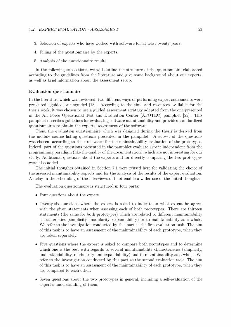
7.2. EXPERT EVALUATION - ASSESSMENT 53
3. Selection of experts who have worked with software for at least twenty years.
4. Filling of the questionnaire by the experts.
5. Analysis of the questionnaire results.
In the following subsections, we will outline the structure of the questionnaire elaboratedaccording to the guidelines from the literature and give some background about our experts,as well as brief information about the assessment setup.
Evaluation questionnaire
In the literature which was reviewed, two different ways of performing expert assessments werepresented: guided or unguided [13]. According to the time and resources available for thethesis work, it was chosen to use a guided assessment strategy adapted from the one presentedin the Air Force Operational Test and Evaluation Center (AFOTEC) pamphlet [55]. Thispamphlet describes guidelines for evaluating software maintainability and provides standardizedquestionnaires to obtain the experts’ assessment of the software.
Thus, the evaluation questionnaire which was designed during the thesis is derived fromthe module source listing questions presented in the pamphlet. A subset of the questionswas chosen, according to their relevance for the maintainability evaluation of the prototypes.Indeed, part of the questions presented in the pamphlet evaluate aspect independent from theprogramming paradigm (like the quality of the documentation), which are not interesting for ourstudy. Additional questions about the experts and for directly comparing the two prototypeswere also added.
The initial thoughts obtained in Section 7.1 were reused here for validating the choice ofthe assessed maintainability aspects and for the analysis of the results of the expert evaluation.A delay in the scheduling of the interviews did not enable a wider use of the initial thoughts.
The evaluation questionnaire is structured in four parts:
• Four questions about the expert.
• Twenty-six questions where the expert is asked to indicate to what extent he agreeswith the given statements when assessing each of both prototypes. There are thirteenstatements (the same for both prototypes) which are related to different maintainabilitycharacteristics (simplicity, modularity, expandability) or to maintainability as a whole.We refer to the investigation conducted by this part as the first evaluation task. The aimof this task is to have an assessment of the maintainability of each prototype, when theyare taken separately.
• Five questions where the expert is asked to compare both prototypes and to determinewhich one is the best with regards to several maintainability characteristics (simplicity,understandability, modularity and expandability) and to maintainability as a whole. Werefer to the investigation conducted by this part as the second evaluation task. The aimof this task is to have an assessment of the maintainability of each prototype, when theyare compared to each other.
• Seven questions about the two prototypes in general, including a self-evaluation of theexpert’s understanding of them.

54 CHAPTER 7. MAINTAINABILITY EVALUATION
One maintainability characteristic which was mentioned in Section 7.1 as a important oneis however not present in this evaluation questionnaire: the testability. This is due to the factthat the experts being provided only the written source code of the prototypes, they wouldhave only been able to evaluate partially the testability of the prototypes, since the testingenvironment was not provided.
During the first assessment task, the experts were asked to say to which extent they agreeto a statement. In order to facilitate the analysis of the answers and following the AFOTECguide, this agreement is given using a Likert scale which is presented in Table 7.2.
Table 7.2: Table explaining the meaning of the different scale items.
RESPONSE MEANING EXPLANATION1 Decidedly Disagree This response indicates the program
being evaluated is terrible with respectto the attribute addressed.
2 Moderately Disagree This response indicates the programbeing evaluated is very poor with re-spect to the attribute addressed.
3 Somewhat Disagree This response indicates the programbeing evaluated is unacceptable withrespect to the attribute addressed.
4 Somewhat Agree This response indicates the programbeing evaluated is barely acceptablewith respect to the attribute addressed.
5 Moderately Agree This response indicates the programbeing evaluated is very good with re-spect to the attribute addressed.
6 Decidedly Agree This response indicates the programbeing evaluated is excellent with re-spect to the attribute addressed.
Since the experts completed the questionnaire on their own, definitions of some terms orexplanations are provided after each statement, in order to limit the misunderstandings. Lastbut not least, the experts are asked to give as many comments as possible about all parts oftheir assessment. Those comments can provide useful information, such as helping to identifywhich characteristics of the paradigms are particularly relevant with regards to maintainability.The full evaluation questionnaire can be found in Appendix E.
Expert panel
The four experts who performed the maintainability assessments were not the same as thefirst group of experts who performed the evaluation of the current implementation (see Section7.1.1). The experts for this part of the maintainability evaluation were software experts workingat Ericsson in different areas not related to the base station implementation. All of them havebeen working with software for at least twenty years.

7.2. EXPERT EVALUATION - ASSESSMENT 55
Assessment
The assessment was performed by the experts on their own. They were provided the writtensource code implementing the peak load scenario for both prototypes and the sequence dia-grams representing the messaging sequences. The material was accessed through the GitHubrepository. They were asked to study the two prototypes and to answer using an online versionof the evaluation questionnaire. They were also given a contact address, if some problemsshould arise when filling in the questionnaire.
7.2.2 Outcome
Four software experts completed the maintainability evaluation questionnaire. Among them,two named the functional paradigm as their favourite programming paradigm and two namedthe object-oriented one. The expert group as a whole was thus not biased towards one pro-gramming paradigm.
Outcome of the first task
First, the agreement of the evaluators on the questions of the first task was calculated, using aformula presented in [47]. This article describes statistical analysis techniques which were usedto validate the AFOTEC methodology.
The formula is:
AG =1
NE
NS∑i=0
NRi
2i
where AG is the agreement factor, NS the number of unit steps in the scoring scale (in ourcase 5), NRi the number of responses which are i steps from the mode1 and NE the numberof evaluators (in our case 4). This formula assigns a weight to each possible response valuedepending on how many evaluators chose it and how far it is from the mode. The closer aresponse value is to the mode, the higher weight it gets. The sum of the weights of all responsevalues is then divided by the number of evaluators to obtain an agreement factor between 0and 1. The calculation of the agreement factors shows that the average agreement factor is0.62 (standard deviation 0.06) for the OOP prototype and of 0.68 (standard deviation 0.10) forthe FRP prototype.This indicates that the experts have different opinions on some questionssince it is below 0.8 (defined in [47] as the threshold for expert agreement). These scores can beexplained by the fact that there were only four experts who answered the questionnaire (whichmeans that the weight of outliers will be important) and also by the fact that the range of thegiven responses was indeed very large on some questions (up to four on a scale of five steps).The agreement measures for each questions can be found in Appendix F.2.
The mean and standard deviation were then calculated for each question of the first task.The results are presented in Table 7.4 for the OOP prototype and in Table 7.5 for the FRPprototype. The mean values are divided in three maintainability levels, each of them corre-sponding to a background colour. Those three levels are presented in Table 7.3 and are derivedfrom the AFOTEC maintainability thresholds.
1In a data set, the mode is the value which appears the highest number of times. For example, in the dataset [1,2,2,2,5], the mode is 2.

56 CHAPTER 7. MAINTAINABILITY EVALUATION
Table 7.3: Maintainability levels according to the score on a question
Score range Maintainability level Colour4.00 - 6.00 Good3.00 - 3.99 Passable1.00 - 2.99 Poor
Table 7.4: Mean and standard deviation for the OOP prototype
Question Mean Standard de-viation
The program contains a reasonable number ofexecutable statements with regards to its pur-pose
2.75 1.50
The program contains a manageable amount ofbranching
3.25 1.71
The program contains manageable levels of nest-ing
3.00 1.41
The program is understandable 3.50 1.29The program clearly allow you to follow the flowof the implemented RRC Connection Setup pro-cedure
4.00 1.41
Overall, the program is simple 4.25 1.26The program clearly separates different concernsfrom each other in the code
3.50 1.73
The program exhibits loose coupling between itsdifferent parts
3.50 1.92
The program exhibits high cohesion within itsdifferent parts
3.75 1.50
Overall, the program is modular 5.00 0.82The program clearly describes how the flow ofthe implemented RRC Connection Setup proce-dure is impacted by the handling of an event
3.50 1.73
Overall, the program is expandable 3.50 1.73Overall, the program is maintainable 3.50 1.73
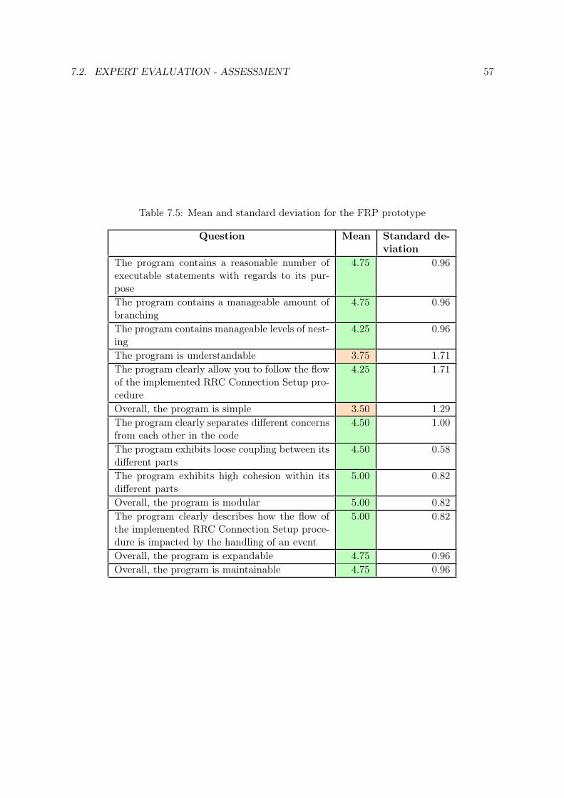
7.2. EXPERT EVALUATION - ASSESSMENT 57
Table 7.5: Mean and standard deviation for the FRP prototype
Question Mean Standard de-viation
The program contains a reasonable number ofexecutable statements with regards to its pur-pose
4.75 0.96
The program contains a manageable amount ofbranching
4.75 0.96
The program contains manageable levels of nest-ing
4.25 0.96
The program is understandable 3.75 1.71The program clearly allow you to follow the flowof the implemented RRC Connection Setup pro-cedure
4.25 1.71
Overall, the program is simple 3.50 1.29The program clearly separates different concernsfrom each other in the code
4.50 1.00
The program exhibits loose coupling between itsdifferent parts
4.50 0.58
The program exhibits high cohesion within itsdifferent parts
5.00 0.82
Overall, the program is modular 5.00 0.82The program clearly describes how the flow ofthe implemented RRC Connection Setup proce-dure is impacted by the handling of an event
5.00 0.82
Overall, the program is expandable 4.75 0.96Overall, the program is maintainable 4.75 0.96
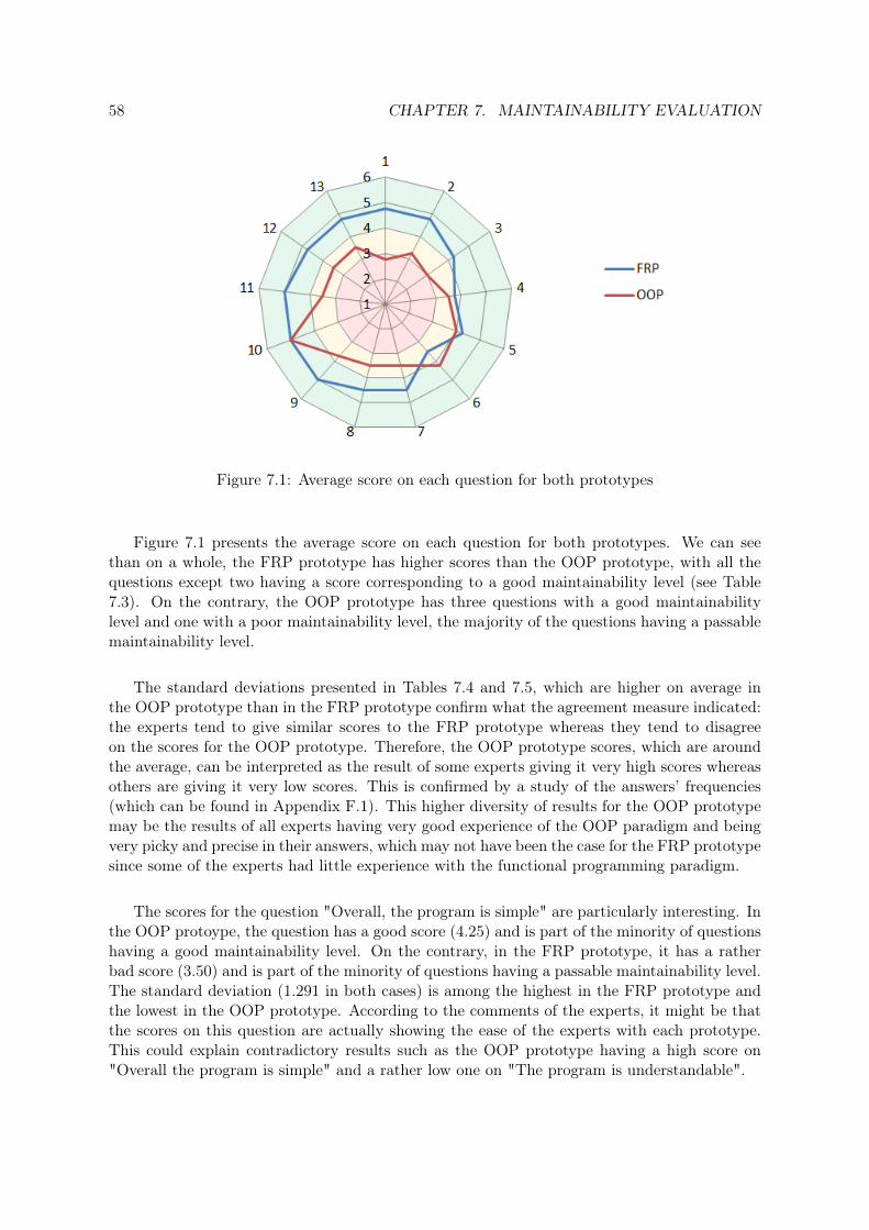
58 CHAPTER 7. MAINTAINABILITY EVALUATION
Figure 7.1: Average score on each question for both prototypes
Figure 7.1 presents the average score on each question for both prototypes. We can seethan on a whole, the FRP prototype has higher scores than the OOP prototype, with all thequestions except two having a score corresponding to a good maintainability level (see Table7.3). On the contrary, the OOP prototype has three questions with a good maintainabilitylevel and one with a poor maintainability level, the majority of the questions having a passablemaintainability level.
The standard deviations presented in Tables 7.4 and 7.5, which are higher on average inthe OOP prototype than in the FRP prototype confirm what the agreement measure indicated:the experts tend to give similar scores to the FRP prototype whereas they tend to disagreeon the scores for the OOP prototype. Therefore, the OOP prototype scores, which are aroundthe average, can be interpreted as the result of some experts giving it very high scores whereasothers are giving it very low scores. This is confirmed by a study of the answers’ frequencies(which can be found in Appendix F.1). This higher diversity of results for the OOP prototypemay be the results of all experts having very good experience of the OOP paradigm and beingvery picky and precise in their answers, which may not have been the case for the FRP prototypesince some of the experts had little experience with the functional programming paradigm.
The scores for the question "Overall, the program is simple" are particularly interesting. Inthe OOP protoype, the question has a good score (4.25) and is part of the minority of questionshaving a good maintainability level. On the contrary, in the FRP prototype, it has a ratherbad score (3.50) and is part of the minority of questions having a passable maintainability level.The standard deviation (1.291 in both cases) is among the highest in the FRP prototype andthe lowest in the OOP prototype. According to the comments of the experts, it might be thatthe scores on this question are actually showing the ease of the experts with each prototype.This could explain contradictory results such as the OOP prototype having a high score on"Overall the program is simple" and a rather low one on "The program is understandable".

7.2. EXPERT EVALUATION - ASSESSMENT 59
Outcome of the second task
The second task asked the experts to compare the two programs on the three maintainabilitycharacteristics which were investigated in the first task (simplicity, modularity and expandabil-ity), plus on understandability (which was part of the simplicity section in the first task) andon maintainability in a whole. Table 7.6 presents the questions asked during the second task.
Table 7.6: Questions for the second task
Number Question32 Indicate the programming paradigm that exhibits the simplest program33 Indicate the programming paradigm that exhibits the most understandable program34 Indicate the programming paradigm that exhibits the most modular program35 Indicate the programming paradigm that exhibits the most expandable program36 Indicate the programming paradigm that exhibits the most maintainable program
The first investigated maintainability characteristic was simplicity. In the evaluation ques-tionnaire, it is indicated that simplicity can be decomposed into program size, control structurecomplexity, data structure complexity and straightforward coding. It is related to the under-standability of the program [55]. According to Figure 7.2, which presents the frequencies ofthe answers, the experts assess the FRP program as the simplest one, which actually gives ancontradictory result to the one obtained when comparing the answers given to question "Over-all, the program is simple" during the first task. This makes the study performed on simplicityunconclusive.
Figure 7.2: Frequencies of the answers to question 32
The second investigated maintainability characteristic was understandability. As defined inthe questionnaire, a part of the program is understandable if the expert is able to understandwhat it does [55]. The results shown in Figure 7.3 indicate that the experts assess both programs

60 CHAPTER 7. MAINTAINABILITY EVALUATION
as equally understandable. However, as it was mentioned by two experts in the comments, thisquestion may be biased towards the paradigm which the expert knows best.
Figure 7.3: Frequencies of the answers to question 33
The third investigated maintainability characteristic was modularity. As explained in thequestionnaire, modular software is composed of largely independent parts [55]. The frequenciesof the answers shown in Figure 7.4 indicate that according to the experts, the programs areequally modular.
Figure 7.4: Frequencies of the answers to question 34
The fourth investigated maintainability characteristic was expandability. A program isexpandable, according to the definition provided in the questionnaire, when it is easy to makechanges and to add new parts to it [55]. Figure 7.5 shows that the experts assessed the FRP
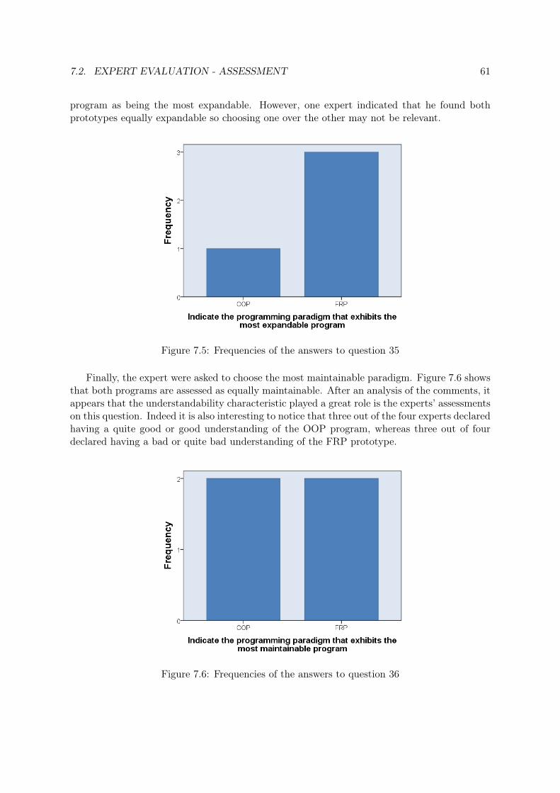
7.2. EXPERT EVALUATION - ASSESSMENT 61
program as being the most expandable. However, one expert indicated that he found bothprototypes equally expandable so choosing one over the other may not be relevant.
Figure 7.5: Frequencies of the answers to question 35
Finally, the expert were asked to choose the most maintainable paradigm. Figure 7.6 showsthat both programs are assessed as equally maintainable. After an analysis of the comments, itappears that the understandability characteristic played a great role is the experts’ assessmentson this question. Indeed it is also interesting to notice that three out of the four experts declaredhaving a quite good or good understanding of the OOP program, whereas three out of fourdeclared having a bad or quite bad understanding of the FRP prototype.
Figure 7.6: Frequencies of the answers to question 36

62 CHAPTER 7. MAINTAINABILITY EVALUATION
Threats to validity and improvements
A potential bias in this study is that some experts having a lot more experience with theobject-oriented programming than with functional programming may tend to favour the firstone because they have troubles understanding the FRP program. Such troubles were indeedmentioned by one expert. Two different improvements to the study could have reduced thissource of bias. The first one would have been to to provide the experts with proper educationin the FRP paradigm to help them understand it. The second would have been to ask peoplewithout any specific knowledge of programming after educating them in both paradigms, assuggested by one expert. Both improvements were however not feasible within the thesis time-frame. Nonetheless, this situation actually reflects the real situation as described by the firstgroup of experts in their initial thoughts: most people have experience and skills in object-oriented programming and only few have experience and skills in functional programming. Thesame understandability problems would probably arise in a real situation as well.
Moreover, this study would greatly benefit from having more experts assessing the twoprototypes. This would increase the reliability of the results by reducing the weight of expertsthat are strongly biased towards one paradigm for any reason. This may also emphasize betterthe differences between the two paradigms.
7.3 Software Metrics
The third part of the maintainability evaluation consisted in using software metrics in order tocompare the maintainability of the OOP and the FRP programs.
7.3.1 Methodology
The chosen approach to conduct this last part of the maintainability evaluation is composed ofthree steps:
1. Review of the literature to find potential metrics.
2. Choice of the metrics to be used.
3. Calculation of the chosen metrics.
Literature review
The aim of the literature review was to find potential metrics to use for the comparison of thetwo prototypes. The review was focused on software metrics which measure maintainability orcharacteristics related to it, such as complexity or readability for example.
Choice of the metrics
During the literature review, some interesting metrics were found such as McCabe’s cyclomaticcomplexity [43], Halstead’s measures [31] or Shao and Wang’s cognitive functional size [52].However, calculating those measures is either time-consuming or requires specific software.Using those measures was thus not possible with the thesis time frame and resources.

7.3. SOFTWARE METRICS 63
Therefore, it was chosen to measure metrics related to the size of the code. Indeed, thosemetrics were mentioned in most of the studies, were found to be successful software maintain-ability predictors [48] and can be calculated easily for both prototypes.
Among the existing code size metrics, the following were measured:
• Number of lines of code (LOC)
• Number of lines of comments (CM)
• Total number of lines in the files
• Average line length
• Number of files
7.3.2 Outcome
The software metrics were calculated on the version of the prototypes which corresponds to theone evaluated by the experts. The UE programs considered in this part are thus the code usedin Scenario 1 of the performance evaluation (with the FRP UE program).
The number of lines of code was measured using the tool Code Analyzer2. The measuresobtained are presented in Table 7.7 for the FRP prototype and Table 7.8 for the OOP prototype.In the latter table, a subtotal has been calculated to separate the files which have been manuallycoded and the files which have been generated by the Google protocol buffers API. The two.proto files used for this generation are presented separately at the end of the table.
Table 7.7: Code size metrics in the FRP implementation
File name Numberof files
Totallines
Averagelinelength
Totalcodelines
Totalcommentlines
Totalwhitespacelines
eNodeB.hs 297 42 251 7 39ue.hs 191 36 161 4 26mme.hs 104 36 81 4 19EventSources.hs 14 20 10 0 4UeContextStates.hs 194 28 160 10 24Identifiers.hs 46 20 35 2 9RrcMessages.hs 146 30 132 3 11S1Messages.hs 79 27 65 4 10LogTools.hs 59 31 51 0 8TOTAL 9 1130 34 957 24 150
These tables show that the total number of lines of code needed to compile the OOPprototype (10990) is a lot higher (more than 11 times more) than the one needed for the FRP
2http://www.codeanalyzer.teel.ws/
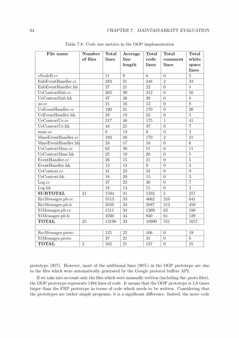
64 CHAPTER 7. MAINTAINABILITY EVALUATION
Table 7.8: Code size metrics in the OOP implementation
File name Numberof files
Totallines
Averagelinelength
Totalcodelines
Totalcommentlines
Totalwhitespacelines
eNodeB.cc 11 9 6 0 5EnbEventHandler.cc 283 31 248 2 33EnbEventHandler.hh 27 21 22 0 5UeContextEnb.cc 262 39 212 0 50UeContextEnb.hh 47 26 39 0 8ue.cc 21 16 13 0 8UeEventHandler.cc 190 31 170 0 20UeEventHandler.hh 28 19 23 0 5UeContextUe.cc 217 40 175 1 41UeContextUe.hh 44 25 37 0 7mme.cc 8 13 6 0 2MmeEventHandler.cc 193 28 170 2 21MmeEventHandler.hh 24 17 18 0 6UeContextMme.cc 62 39 51 0 11UeContextMme.hh 25 19 20 0 5EventHandler.cc 26 15 21 0 5EventHandler.hh 12 12 9 0 3UeContext.cc 41 23 32 0 9UeContext.hh 18 20 15 0 3Log.cc 37 23 30 0 7Log.hh 18 14 15 0 3SUBTOTAL 21 1594 31 1332 5 257RrcMessages.pb.cc 5513 33 4662 210 641RrcMessages.pb.h 3550 33 2887 213 450S1Messages.pb.cc 1511 34 1269 62 180S1Messages.pb.h 1030 34 840 61 129TOTAL 25 13198 33 10990 551 1657
RrcMessages.proto 125 22 106 0 19S1Messages.proto 37 21 31 0 6TOTAL 2 162 21 137 0 25
prototype (957). However, most of the additional lines (96%) in the OOP prototype are dueto the files which were automatically generated by the Google protocol buffers API.
If we take into account only the files which were manually written (including the .proto files),the OOP prototype represents 1494 lines of code. It means that the OOP prototype is 1.6 timeslarger than the FRP prototype in terms of code which needs to be written. Considering thatthe prototypes are rather simple programs, it is a significant difference. Indeed, the more code

7.4. CONCLUSION OF THE MAINTAINABILITY EVALUATION 65
is to be written, the more probable it is for the programmer to make a mistake which will laterneed a maintenance operation: simplicity is an important maintainability characteristic.
However, in addition to the fact that changing or adding a message means having to recom-pile the .proto files (which might be time-consuming for large files: for the OOP prototype, ittook 0.140s), the generated C++ files need to be understood in order to use the messages inthe OOP prototype (for example to know how to fill a field of a message). In this case, a pro-grammer who is not familiar with the implementation needs to browse through 11.5 times morelines of code to be able to work with it. This can lead to a huge difference in the time neededto perform a maintenance task since no programmer knows the complete implementation ofthe base station3.
The average line length is similar between the two prototypes, with the OOP prototypehaving a slightly lower value. Small average line length is indeed better for the readability ofthe programs [21].
Moreover, there is also a big difference in the number of files in each prototype. With 23manually written files in the OOP prototype and 9 in the FRP prototype, the OOP prototypecontains 2.6 times more files than the FRP, which also contributes to make the source codemore complex.
Last but not least, when focusing on the parts of the code dealing with the events, differencesbetween the prototypes are also present. For example, the code parts which handle the RRCconnection request consist of 30 lines in the OOP prototype (see Snippet 5.8) and 16 lines inthe FRP one (see Snippet 5.4). Moreover, in the FRP prototype, 5 of the 16 lines are actuallyused by several messages, thus showing that the FRP paradigm more easily enables to reusecode, which is a good feature for maintainability.
Another example is receiving a UE message, decoding it and calling the function whichhandles it. It corresponds to 12 lines in the OOP prototype (see Snippet 5.6) and to 2 lines inthe FRP one (see Snippet 5.3). This is because the FRP prototype, in addition to having higherabstractions for event-handling with the FRP framework, benefits from the high abstractionlevel of Haskell as a whole, here with the abstractions dealing with the reception and decodingof a message arriving in the TCP network. Being able to have higher abstractions was part ofthe experts’ wishes (see Section 7.1).
7.4 Conclusion of the maintainability evaluation
The maintainability evaluation of the two prototypes consisted in a combination of experts’assessments and of structural measures. During the literature review, it was found that sucha combination has been proven to be the most efficient way to assess the maintainability ofsoftware [13].
The first part of the maintainability evaluation was an investigation of how three expertsworking with the real implementation of the base station understood its maintainability. Theobtained initial thoughts show, for example, that high level abstractions are desirable. More-over, the initial thoughts indicated that the maintainability of a FRP base station would beaffected by the persons working with it, since FRP is not currently very well-known.
3This was one of the initial thoughts of Section 7.1

66 CHAPTER 7. MAINTAINABILITY EVALUATION
The important aspects discovered during this first part were then studied through an expert-based assessment. During this assessment, the experts evaluated the FRP prototype better thanthe OOP prototype in 11 of the 13 questions composing the first evaluation task. Moreover,when asked to compare the two prototypes, the FRP was assessed better or equal to the OOPprototype on all criteria4. According to the participating experts, the FRP prototype is thus themost maintainable. The evaluation of the two prototypes also showed that the FRP prototypeprovides higher level abstractions compared to the OOP one, which was one of the desirablecharacteristics mentioned in the initial thoughts. The thought that the maintainability of aFRP base station would be affected by the persons working with it was also brought up by theexperts performing the assessment of the two prototypes.
Finally, structural measures were investigated. The measures used were related to code size.They show that the FRP implementation is smaller than the OOP one with regards to numberof code lines and number of files. Moreover, the number of code lines needed to implementevent-handling is at least reduced by two when using the FRP framework. Finally, the twoprototypes perform comparably on readability (this is confirmed by the experts’ assessment ofquestion "The program clearly allow you to follow the flow of the implemented RRC ConnectionSetup procedure"). According to the chosen software metrics, the FRP prototype is thus themost maintainable.
Therefore, the maintainability evaluation of the two prototypes shows that the FRP proto-type is more maintainable than the OOP one.
However, the initial thoughts from the real implementation also mentioned areas that werenot investigated in the evaluation of the prototypes due to practical and time reasons. The firstone is the testability of the programs and the second one is the scale of the programs, the realbase station being a huge program whereas the prototypes are rather small ones. However, itwas out of the scope of the thesis to investigate if all of the desirable characteristics could beprovided by the FRP paradigm.
4The study on simplicity being unconclusive because of contradictory results between the two assessments.

Chapter 8
Conclusions and future work
This last chapter presents the conclusions of the thesis work, further investigations which couldbe conducted as well as personal reflections on the thesis work.
8.1 Conclusions
We can now answer the thesis hypothesis which was formulated in Section 1.2: using FRPas a programming model leads to a more maintainable but not suitably performing programcompared to the current OOP paradigm.
The goals defined for the thesis work are fulfilled. First, a theoretical investigation ofFRP, including a survey of the existing frameworks, was performed. Then, two prototypesimplementing the same reference model were developed, one using the FRP paradigm and oneusing the OOP paradigm. Finally, those two prototypes were compared regarding performanceand maintainability. The performance evaluation consisted of two scenarios: one representing apeak load situation and one representing a spread load situation. The maintainability evaluationused experts’ initial thoughts, experts’ assessment and software metrics.
At the end of the performance and maintainability evaluations presented in the two preced-ing chapters, the FRP prototype is assessed as more maintainable than the OOP one but theOOP prototype performs better than the FRP prototype in terms of average time needed for aUE to attach, CPU usage and memory usage. It was also shown that both prototypes performbetter in a spread load situation than in a peak load situation, both in terms of time needed toattach a UE and maximum number of UEs which can be handled by the prototype. However,even if the performance of the prototypes cannot be directly compared to the performance ofthe real base station, some input about the performance of the real base station will be usedto determine whether the prototypes perform suitably. Indeed, since the prototypes implementa simplified version of the connection setup procedure in a simplified base station, they areexpected to perform better than the real implementation on certain aspects like execution timeand number of UE handled.
The performances expected in the real base station are the following: a UE should attach inless than 100ms, with slightly less than 10% of this time (meaning less than 10 ms) dedicated tothe control plane procedures such as the RRC connection setup procedure (the rest of the timebeing used for radio and baseband signalling). The FRP prototype performances, as evaluatedduring the two scenarios presented in Chapter 6, are thus not suitable for an implementation
67

68 CHAPTER 8. CONCLUSIONS AND FUTURE WORK
in the real base station, as the FRP prototype, which only implements the RRC connectionsetup procedure, needs more than 10 ms to perform a simplified attach of a UE.
Nevertheless, according to the results of the performance evaluation, the FRP prototypeusing reactive-banana did not have (for the investigated number of UEs) the dreaded spaceand time leaks (mentioned in Section 3.3.1) which were a big problem in preceding FRP imple-mentations. Yet, having a lot of FRP networks running in the same operating system thread(as in the UE program) decreases the performance of the prototype. Nonetheless, the FRPprototype using the classic functional UE program, although faster than the one using onlyreactive-banana, sometimes has a time leak when more than 500 UEs were involved.
However, some aspects of this thesis work may weaken those conclusions. First, the main-tainability evaluation was conducted with a limited number of experts, meaning that the resultsare influenced by the opinion of those specific experts. Moreover, the experts were not giventraining, particularly regarding FRP. This may have affected their assessment. Finally, the pro-totypes were developed with basic knowledge and experience of both OOP and FRP. Thereforethey may not be representative of what experts in those paradigms can achieve and this mayaffect both the performance and the maintainability of the prototypes.
Finally we conclude with a reflection about the problem. In this thesis, we have investigatedhow a new programming model, FRP, could lead to a less complex code and thus an increasedmaintainability for the telecom servers. However, the thesis work showed that maintainabilityof the telecom servers encompasses other areas than the ones strictly related to the code. Forexample the workflow used with the programming model is also very important. However, thestudy of these other areas was outside the scope of this thesis.
8.2 Future investigations
This section presents ideas for further investigations of the performance or maintainabilityevaluation of the FRP paradigm, but which did not fit ether in the time frame or in the scopeof this thesis.
8.2.1 About performance
As it have been already mentioned, the prototypes are different from the real implementationon several aspects. The prototypes are indeed a simplified version of the real implementationand interact with simulated UEs and MME. In order to know the performance of the reactive-banana framework in real conditions and to test how easy or hard it is to use with the existingsoftware, it would be interesting to implement the RRC connection setup procedure completelyand to integrate it with the real base station software. Moreover, it would then be possible tocheck if time leaks sometimes occur in real conditions. Finally, performing a formal analysiscould find the potential deadlocks (or prove their absence).
Then, Heinrich Apfelmus, the developer and maintainer of reactive-banana, announced onhis blog [14] that he will focus on improving the efficiency of the framework for the next releasesof reactive-banana. The performance discrepancies between the FRP prototype and the OOPprototype may thus diminish or even disappear with a future release of the FRP framework, so itmay be interesting to perform the tests again with an improved version of the FRP framework.

8.3. PERSONAL REFLECTION ON THE THESIS WORK 69
8.2.2 About maintainability
The maintainability evaluation could be enlarged with the investigation of the testability char-acteristic, which was mentioned as important in the experts’ initial thoughts. Moreover, sincethe FRP prototype may need to use different tools than the one used currently with the im-plementation of the base station, it could be interesting to investigate the tool support thatthe FRP paradigm offers. In addition, the FRP paradigm may provide support in aspects thatwere mentioned as desirable by the experts, such as offering a way to extract high-level viewsof the software, so it could be interesting to investigate the other desirable aspects mentionedby the experts such as testability.
The experts also emphasized that changing the paradigm which is used for programmingimplies a lot of changes, ranging a new language to change of tools. A further study of allthe impacts of changing the paradigm would thus have to be carried carefully before actuallychanging the paradigm.
8.2.3 About the FRP paradigm in general
Finally, it would be interesting to investigate further other FRP paradigms. Indeed, reactive-banana was chosen because it fitted the requirements for this thesis when the survey of theframeworks was made. However, a lot of research and development is currently going on aroundthe FRP paradigm and there may be an alternative framework in the future which would bemore suitable for the base station implementation.
8.2.4 About the prototypes
As mentioned before, the prototypes developed during this thesis are lacking comprehensiveerror-handling. Adding this would enable the prototypes to be closer to what is expected froma real implementation. It would also enable to compare the amount of code needed for thispurpose in both paradigms.
Moreover, it could be interesting to ask an expert in each of the paradigms to implement thereference model and compare the performance and maintainability of the resulting programswith the ones developed in this thesis to know if the experience of the programmer has animpact and if yes, the extent of it.
8.3 Personal reflection on the thesis work
First I would like to examine whether my own background as a Computer Science studentcould have influenced this thesis work. I have encountered both the object-oriented and thefunctional programming paradigms during my studies, so I was already familiar with both thoseapproaches before the thesis work. I am also comfortable with both paradigms. Therefore, Ithink that the thesis work was not influenced by a personal preference for one paradigm over theother. Regarding the languages, I had some university experience of programming with C++whereas Haskell and the reactive-banana framework were completely new to me. However, Ihad the prototypes reviewed by someone experienced in both languages to avoid any beginnermistake in the prototypes which could compromise the study. Therefore, I think that my ownbackground had a limited influence on the conclusions of this thesis.

70 CHAPTER 8. CONCLUSIONS AND FUTURE WORK
Then, I would like to reflect on the thesis process. There were a lot of interesting investi-gations possible during this thesis but it was not possible to carry them out within the thesistimeframe. Therefore having a clear scope for the work from the beginning was very importantin order to prioritize the work to do. Moreover, I have improved my prioritizing skills alongthe thesis and I think that if I had to do a similar work again, I would allocate less time forthe litterature review and for the framework selection, knowing what time is actually neededfor implementing and evaluating the prototypes (which I had a bit underestimated). I wouldalso define a clear scope for each phase of the work at the beginning of them in order to be ableto refer to it when having to decide whether to investigate a new idea or not, and thus avoidinvestigating too many "nice but a bit unrelated" areas and have more time to dig deeper inthe areas which are the most relevant for the thesis.

References
[1] About 3gpp. http://www.3gpp.org/About-3GPP. (accessed on 15/05/2014).
[2] Yampa - haskellwiki. http://www.haskell.org/haskellwiki/Yampa, 2012. (accessed on30/07/2014).
[3] The reactive manifesto (v.1.1). http://www.reactivemanifesto.org, September 2013.(accessed on 19/03/2014).
[4] Erlang programming language. http://www.erlang.org/, 2014. (accessed on27/07/2014).
[5] Observer pattern - what happened to scala.react? - stack overflow. http://stackoverflow.com/questions/21546456/what-happened-to-scala-react, 2014. (ac-cessed on 31/03/2014).
[6] Reactive-banana - haskell wiki. http://www.haskell.org/haskellwiki/Reactive-banana, 2014. (accessed on 28/07/2014).
[7] ReactiveML. http://rml.lri.fr/, June 2014. (accessed on 27/07/2014).
[8] 3GPP. Protocol specification of Radio Resource Control - 3GPP TS 36.331, December2013. V12.0.0, http://www.3gpp.org/DynaReport/36331.htm.
[9] S. Ahmadi. LTE-advanced : a practical systems approach to understanding the 3GPP LTEreleases 10 and 11 radio access technologies. Academic Press, Oxford, U.K., 2014.
[10] E. Amsden. A survey of functional reactive programming. Concepts, implementations,optimizations, and applications. Unpublished, 2011.
[11] E. Amsden. eamsden/pushbasedfrp - github. https://github.com/eamsden/pushbasedFRP, 2013. (accessed on 30/07/2014).
[12] E. Amsden. Timeflies: Push-pull signal-function functional reactive programming. Mas-ter’s thesis, Rochester Institute of Technology, August 2013.
[13] B. Anda. Assessing software system maintainability using structural measures and ex-pert assessments. In Proceedings of the 2007 IEEE International Conference on SoftwareMaintenance (ICSM 2007), pages 204–213. IEEE, 2007.
[14] H. Apfelmus. apfelmus - blog posts and articles. http://apfelmus.nfshost.com/blog.html, 2014. (accessed on 29/07/2014).
71

72 REFERENCES
[15] H. Apfelmus. apfelmus - FRP - release of reactive-banana version 0.8. http://http://apfelmus.nfshost.com/blog/2014/01/29-frp-banana-0-8.html, 2014. (article pub-lished on 29/01/2014).
[16] J. Armstrong. A history of Erlang. In Proceedings of the Third ACM SIGPLAN Conferenceon History of Programming Languages (HOPL III), pages 6–1–6–26. ACM, 2007.
[17] E. Bainomugisha, A. Lombide Carreton, T. Van Cutsem, S. Mostinckx, and W. De Meuter.A survey on reactive programming. ACM Computing Surveys, 45(4):52 – 52:34, 2013.
[18] G. Baudart, L. Mandel, and M. Pouzet. Programming mixed music in ReactiveML. InACM SIGPLAN Workshop on Functional Art, Music, Modeling and Design (FARM’13).ACM, September 2013.
[19] C. Belwal, A. M. K. Cheng, J. Ras, and Y. Wen. Variable voltage scheduling with thepriority-based functional reactive programming language. In Proceedings of the 2013 Re-search in Adaptive and Convergent Systems (RACS ’13), pages 440–445. ACM, 2013.
[20] J. Brooks and P. Frederick. No silver bullet essence and accidents of software engineering.Computer, 20(4):10–19, April 1987.
[21] R. P. L. Buse andW. R. Weimer. Learning a metric for code readability. IEEE Transactionson Software Engineering, 36(4):546 – 558, 2010.
[22] M. H. Cheong. Functional programming and 3d games. Bachelor thesis, The Universityof New South Wales School of Computer Science and Engineering, 2005.
[23] A. Courtney. Frappé: Functional reactive programming in java. In Practical Aspects ofDeclarative Languages 3rd International Symposium (PADL 2001), pages 29–44. Springer,2001.
[24] A. Courtney and C. Elliott. Genuinely functional user interfaces. In Preliminary Proceed-ings of the 2001 Haskell Workshop (HW’2001), pages 41–69. Department of Informationand Computing Sciences, Utrecht University, 2001.
[25] A. Courtney, H. Nilsson, and J. Peterson. The yampa arcade. In Proceedings of the 2003ACM SIGPLAN Haskell Workshop, pages 7–18. ACM, 2003.
[26] E. Czaplicki. Elm: Concurrent FRP for Functional GUIs. Senior thesis, Harvard Univer-sity, March 2012.
[27] C. Elliott. Push-pull functional reactive programming. In Proceedings of the 2009 ACMSIGPLAN Haskell Symposium (Haskell’09), pages 25–36. ACM, 2009.
[28] C. Elliott and P. Hudak. Functional reactive animation. In Proceedings of the SecondACM SIGPLAN International Conference on Functional Programming (ICFP ’97), pages263–273. ACM, 1997.
[29] E. Gamma, R. Helm, R. Johnson, and J. Vlissides. Design Patterns - Elements of reusableObject-Oriented Software. Addison-Wesley, 1995.

REFERENCES 73
[30] G. Giorgidze and H. Nilsson. Switched-on yampa, declarative programming of modularsymthesizers. In Practical Aspects of Declarative Languages 10th International Symposium(PADL 2008), pages 282–298. Springer, 2008.
[31] M. H. Halstead. Elements of Software Science (Operating and Programming Systems Se-ries). Elsevier Science Inc., New York, NY, USA, 1977.
[32] P. Hudak, A. Courtney, H. Nilsson, and J. Peterson. Arrows, robots, and functionalreactive programming. Advanced Functional Programming, 2638:159–187, 2003.
[33] Typesafe Inc. Akka. http://akka.io/, 2014. (accessed on 27/07/2014).
[34] A. Jeffrey. Functional reactive programming with liveness guarantees. In Proceedings of the18th ACM SIGPLAN International Conference on Functional Programming (ICFP ’13),pages 233–244. ACM, 2013.
[35] S.P. Jones, A. Gordon, and S. Finne. Concurrent haskell. In Proceedings of the 23rd ACMSIGPLAN-SIGACT Symposium on Principles of Programming Languages, pages 295–308.ACM, 1996.
[36] J. Larson. Erlang for concurrent programming. Communications of the ACM, 52(3):48–56,2009.
[37] E.A. Lee and D.G. Messerschmidt. Synchronous data flow: Describing signal processingalgorithms for parallel computation. In Digest of Papers - COMPCON Spring ’87. Thirty-Second IEEE Computer Society International Conference: Intellectual Leverage, pages310–313. IEEE, 1987.
[38] C. K. K. Loverdos and A. Syropoulos. Steps in Scala: an introduction to object-functionalprogramming, chapter 1. Cambridge University Press, New York, 2010.
[39] I. Maier. ingoem/scala-react - github. https://github.com/ingoem/scala-react, 2012.(accessed on 29/07/2014).
[40] I. Maier and M. Odersky. Deprecating the observer pattern with scala.react. TechnicalReport 176887, EPFL, 2012.
[41] I. Maier and M. Odersky. Higher-order reactive programming with incremental lists. InECOOP 2013 - Object-Oriented Programming, pages 707–731. Springer-Verlag, 2013.
[42] L. Mandel and M. Pouzet. ReactiveML, a reactive extension to ML. In Proceedings of theSeventh ACM SIGPLAN Conference on Principles and Practice of Declarative Program-ming (PPDP’05), pages 82–93. ACM, 2005.
[43] T.J. McCabe. A complexity measure. IEEE Transactions on Software Engineering, SE2(4):308–320, 1976.
[44] H. Nilsson, A. Courtney, and J. Peterson. Functional reactive programming, continued.In Proceedings of the 2002 ACM SIGPLAN Haskell Workshop, pages 51–64. ACM, 2002.
[45] B. O’Sullivan. Performance measurement and optimization in haskell [video file]. https://skillsmatter.com/skillscasts/5466-bryan-o-sullivan, October 2014.

74 REFERENCES
[46] R. Paterson. A new notation for arrows. In Proceedings of the Sixth ACM SIGPLANInternational Conference on Functional Programming (ICFP ’01), pages 229–240. ACM,2001.
[47] D. E. Peercy. Software maintainability evaluation methodology. IEEE Transactions onSoftware Engineering, 7(4):343 – 351, 1981.
[48] M. Riaz, E. Mendes, and E. Tempero. A systematic review of software maintainability pre-diction and metrics. In Third International Symposium on Empirical Software Engineeringand Measurement, pages 367 – 377. IEEE, 2009.
[49] G. Salvaneschi, J. Drechsler, and M. Mezini. Towards distributed reactive programming.In Coordination Models and Languages 15th International Conference. Springer, 2013.
[50] L. Samper, F. Maraninchi, L. Mounier, and L. Mandel. Glonemo: Global and accurateformal models for the analysis of ad hoc sensor networks. In Proceedings of the First Inter-national Conference on Integrated Internet Ad hoc and Sensor Networks (InterSense’06).ACM, May 2006.
[51] N. Sculthorpe and H. Nilsson. Safe functional reactive programming through dependenttypes. In Proceedings of the 14th ACM SIGPLAN International Conference on FunctionalProgramming (ICFP ’09), pages 23–34. ACM, 2009.
[52] J. Shao and Y. Wang. A new measure of software complexity based on cognitive weights.Canadian Journal of Electrical and Computer Engineering, 28(2):69 – 74, 2003.
[53] M. Sperber. Computer-Assisted Lighting Design and Control. PhD thesis, University ofTübingen, June 2001.
[54] S. Tasharofi. Actor analysis. http://actor-applications.cs.illinois.edu/akka.html.(accessed on 27/07/2014).
[55] Air Force Operational Test and Evaluation Center (AFOTEC). Software maintainabilityevaluation guide. 1996.
[56] M. Thurau. Akka framework. http://media.itm.uni-luebeck.de/teaching/ws2012/sem-sse/martin-thurau-akka.io.pdf. University of Lübeck.
[57] Tutorialspoint. LTE network architecture. http://www.tutorialspoint.com/lte/lte_network_architecture.htm. (accessed on 15/05/2014).
[58] A. van der Ploeg. Monadic functional reactive programming. In Proceedings of the 2013ACM SIGPLAN Symposium on Haskell (Haskell ’13), pages 117–128. ACM, 2013.
[59] Z. Wan and P. Hudak. Functional reactive programming from first principles. In Pro-ceedings of the ACM SIGPLAN 2000 Conference on Programming Language Design andImplementation, pages 242–252. ACM, 2000.
[60] Z. Wan, W. Taha, and P. Hudak. Real-time FRP. In Proceedings of the Sixth ACMSIGPLAN International Conference on Functional Programming (ICFP ’01), pages 146–156. ACM, 2001.

REFERENCES 75
[61] Z. Wan, W. Taha, and P. Hudak. Event-driven FRP. In Practical Aspects of DeclarativeLanguages 4th International Symposium (PADL 2002), pages 155–172. Springer, 2002.
[62] J. Wannstrom. LTE-advanced. http://www.3gpp.org/technologies/keywords-acronyms/97-lte-advanced, June 2013. (accessed on 15/05/2014).

Appendix A
Survey of the frameworks
Table A.1: Framework list summarizing the preliminary selection outcome
Name of theframework
Hostlanguage
Decision
DataDriven Haskell RejectedDire Scala RejectedElerea Haskell RejectedElm Elm RejectedEuphoria Haskell RejectedFlapjax JavaScript RejectedFran Haskell RejectedFrappé Java RejectedFrenetic OCaml RejectedFroc OCaml RejectedFrTime Racket RejectedGrapefruit Haskell RejectedNetwire Haskell RejectedOrdrea Haskell RejectedPyretic Python RejectedReactive Haskell RejectedReactive-banana
Haskell Selected
Scala.React Scala SelectedSodium Haskell RejectedTimeFlies Haskell SelectedYampa Haskell Selected
76
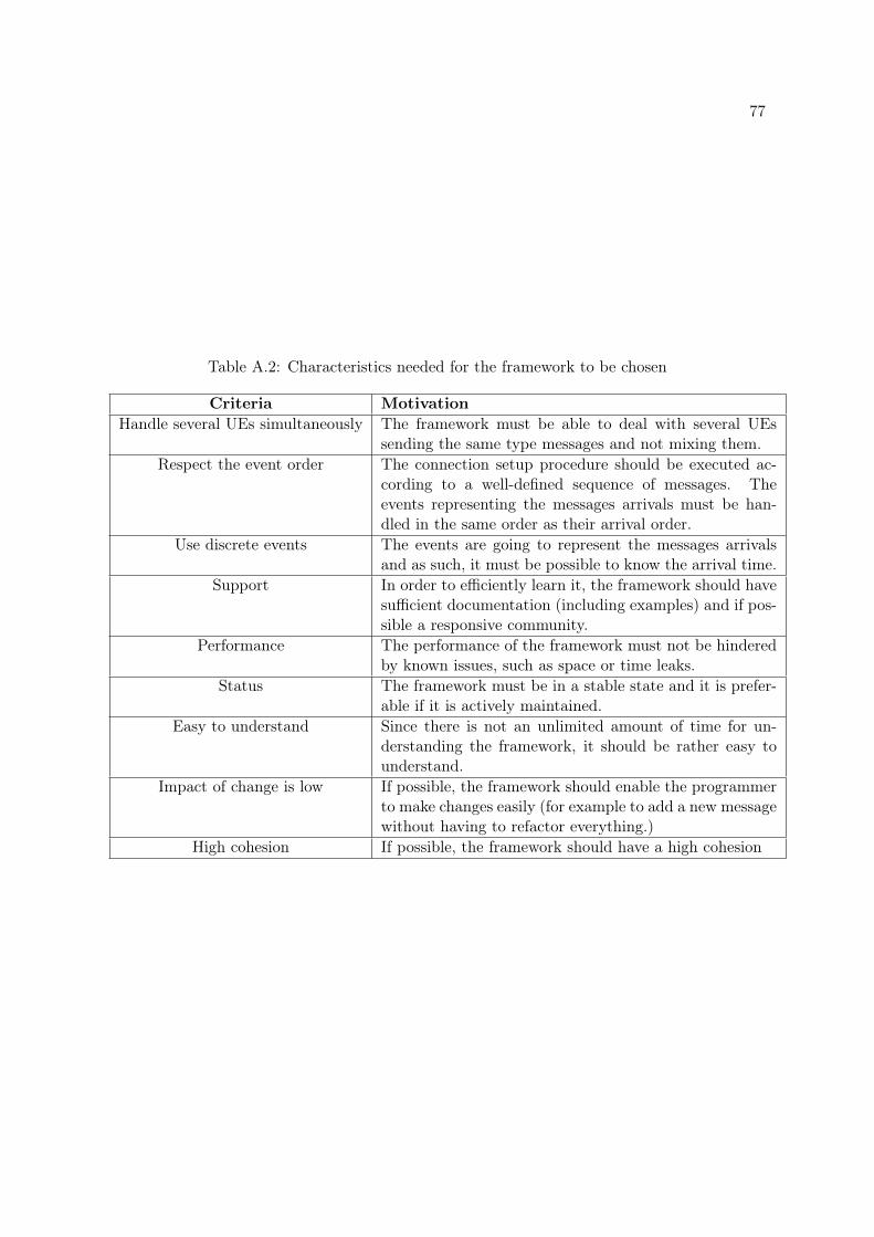
77
Table A.2: Characteristics needed for the framework to be chosen
Criteria MotivationHandle several UEs simultaneously The framework must be able to deal with several UEs
sending the same type messages and not mixing them.Respect the event order The connection setup procedure should be executed ac-
cording to a well-defined sequence of messages. Theevents representing the messages arrivals must be han-dled in the same order as their arrival order.
Use discrete events The events are going to represent the messages arrivalsand as such, it must be possible to know the arrival time.
Support In order to efficiently learn it, the framework should havesufficient documentation (including examples) and if pos-sible a responsive community.
Performance The performance of the framework must not be hinderedby known issues, such as space or time leaks.
Status The framework must be in a stable state and it is prefer-able if it is actively maintained.
Easy to understand Since there is not an unlimited amount of time for un-derstanding the framework, it should be rather easy tounderstand.
Impact of change is low If possible, the framework should enable the programmerto make changes easily (for example to add a new messagewithout having to refactor everything.)
High cohesion If possible, the framework should have a high cohesion

Appendix B
Messaging sequences
Figure B.1: Messaging sequence during a failed connection setup procedure: rejection of theRRC connection request
78

79
Figure B.2: Messaging sequence during a failed connection setup procedure: failure of thesecurity mode
Figure B.3: Messaging sequence during a failed connection setup procedure: failure of the RRCconnection reconfiguration

Appendix C
Content of the UE context
Table C.1: Data stored for each UE in the MME
UE contextMME UE S1 AP idSecurity key
Table C.2: Data stored for each UE in the eNodeB
UE contextRRC state (idle or connected)C-RNTIIMSISRB identityeNodeB UE S1 AP idRadio Access Technologies capabilitiesSecurity key (for the encryption)Evolved Packet System bearer id
80

Appendix D
Interview questionnaires
D.1 Preliminary questionnaire
81

Expert evaluation of the current implementation 1
Questionnaire for the expert evaluation of thecurrent implementation
The aim of this questionnaire is to give directions to the experts in order to get their insights about themaintainability of the current implementation of a LTE base station and more particularly of the RRC Protocol.
About the expert
1. Name of the expert:
2. How long have you been working with the LTE base station implementation?
3. Please explain briefly what are the tasks you perform here at Ericsson (related to the basestation or not).
About maintainability in general
4. What is maintainability for you ?
About the maintenance of the base station implementation
5. Could you describe what the maintenance environment looks like? Some sketches of the orga-nization of the software used are planed to be made on separate sheets of paper.
6a. Could you describe usual maintenance tasks? (What needs to be done/How it is done/Orderthem from the one that is the most often performed to the least often performed)
6b. How often do you perform them?
7a. When performing maintenance tasks, do you sometimes spend time on part of the codenon-directly related to the original task? 2 Yes 2 No
7b. If yes, on which parts of the code?
7c. If yes, is this more or less time-consuming than the original task alone?
8a. Would you say that a clear separation of concerns is achieved in the implementation ?(protocol logic, state handling, event handling, concurrent execution)
2 No
2 Rather no
2 Rather yes
2 Yes
8b. Why?
9. Please give a grade (between 1 and 10) to the maintainability of the current implementation.(1 means no maintainability at all and 10 means perfect maintainability)
10. What makes maintaining the code difficult for you?
11. What makes maintaining the code easy for you?
12. What would you like to change in the current implementation to make it more maintainable(even if not technically possible)?
More specific aspects of maintainability
Understandability
13. How much time did it take you to understand the implementation? 2 I don’t remember2 Time:(how long?)
82 APPENDIX D. INTERVIEW QUESTIONNAIRES
D.2 Interview questionnaire

Expert evaluation of the current implementation 2
14a. Would you say that understanding the base station implementation was ?
2 Difficult
2 Rather difficult
2 Rather easy
2 Easy
2 Doesn’t remember
14b. Why?
Simplicity
15a. Do you think that it is possible to make the implementation simpler? 2 No 2 Yes
15b. Why?
15c. If yes, how?
Expandability
16a. Please evaluate the following task using a number between 1 and 10 (1 means it’s extremelydifficult and 10 that it’s extremely easy):
You have to add a new message in the middle of the current message sequence.
16b. Check all the following words/sentences that would apply to the task :
2 time-consuming
2 quick
2 will probably introduce errors (error-prone)
2 won’t introduce errors
2 hard to locate where to modify the code
2 easy to locate where to modify the code
2 hard to test
2 easy to test
2 Other:
16c. Could you explain why?
Making changes
17a. Please evaluate the following task using a number between 1 and 10 (1 means it’s extremelydifficult and 10 that it’s extremely easy):
You have to change the behavior of the program when a specific message is received.
17b. Check all the following words/sentences that would apply to the task :
2 time-consuming
2 quick
2 will probably introduce errors (error-prone)
2 won’t introduce errors
2 hard to locate where to modify the code
2 easy to locate where to modify the code
2 hard to test
2 easy to test
2 Other:
17c. Could you explain why?
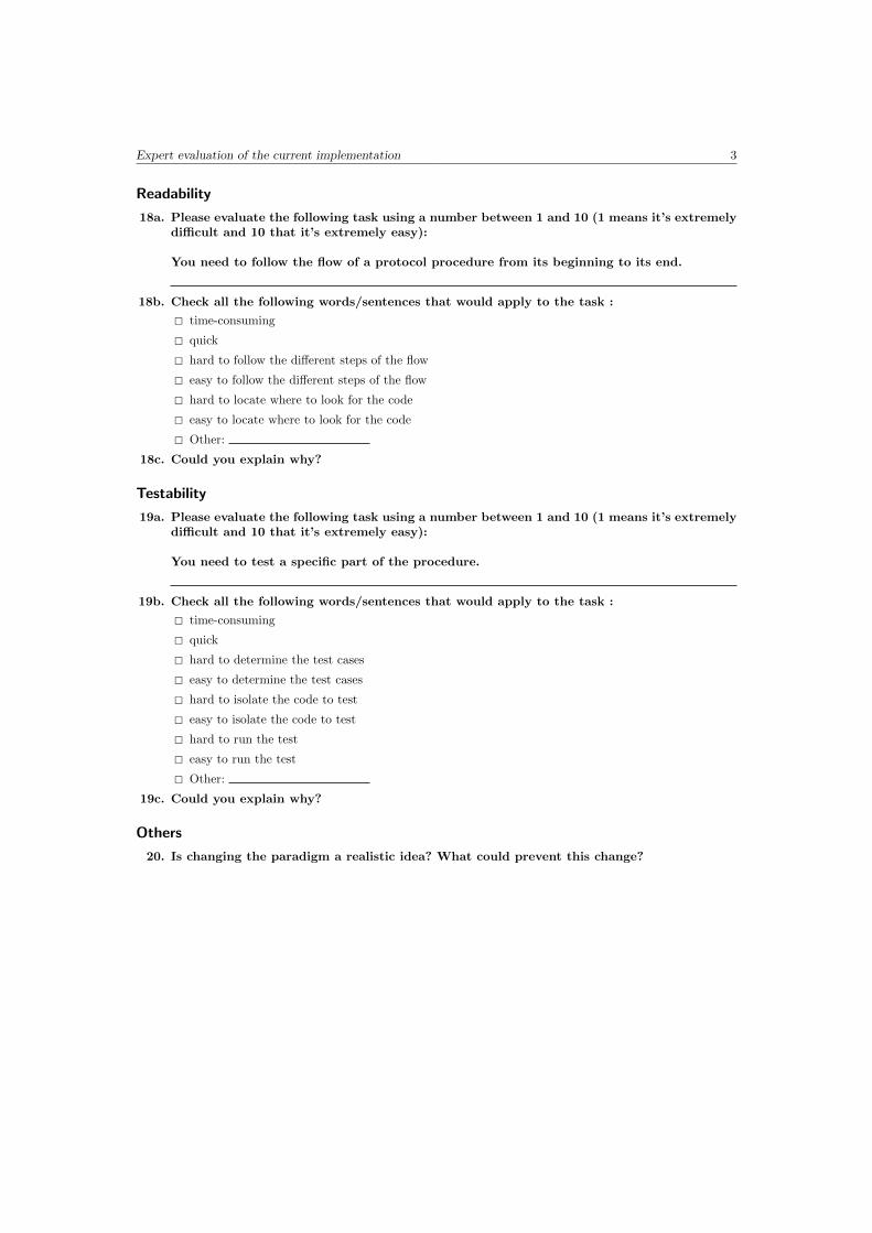
Expert evaluation of the current implementation 3
Readability
18a. Please evaluate the following task using a number between 1 and 10 (1 means it’s extremelydifficult and 10 that it’s extremely easy):
You need to follow the flow of a protocol procedure from its beginning to its end.
18b. Check all the following words/sentences that would apply to the task :
2 time-consuming
2 quick
2 hard to follow the different steps of the flow
2 easy to follow the different steps of the flow
2 hard to locate where to look for the code
2 easy to locate where to look for the code
2 Other:
18c. Could you explain why?
Testability
19a. Please evaluate the following task using a number between 1 and 10 (1 means it’s extremelydifficult and 10 that it’s extremely easy):
You need to test a specific part of the procedure.
19b. Check all the following words/sentences that would apply to the task :
2 time-consuming
2 quick
2 hard to determine the test cases
2 easy to determine the test cases
2 hard to isolate the code to test
2 easy to isolate the code to test
2 hard to run the test
2 easy to run the test
2 Other:
19c. Could you explain why?
Others
20. Is changing the paradigm a realistic idea? What could prevent this change?

Appendix E
Evaluation questionnaire
85

Evaluation Questionnaire 1
Evaluation Questionnaire
You are presented two small computer software programs. Each program is implementing the same task,and implementing the same functional and non-functional requirements. The task implemented is typical fortelecommunications control systems and is modelled from the RRC connection setup procedure in LTE. Severalsequence diagrams modelling the different flows of the procedure implemented are available in the evaluationmaterial.
The programs are implemented using two different programming paradigms: one is using the object-orientedprogramming paradigm and the other is using the functional reactive programming paradigm. Both programsare implemented in what is regarded as idiomatic style for their respective paradigms.
The first task is to assess the two programs with regards to maintainability. Hence you are asked to answertwo identical sets of questions, one for each paradigm. Please give as detailed answers as possible and do nothesitate to write comments.
The second task is to compare the two programs with regards to several maintainability characteristics.
How to answer? Fill in the online questionnaire.
1. Your name:
1 About you
2. How long have you been working with software ?Note: Including both experience within the software industry and other software development experience(e.g. open source projects)
3. Please explain briefly what are the tasks you perform here at Ericsson
4. What programming paradigm(s) are you experienced in?Note: Examples of programming paradigms: functional, object-oriented, declarative, imperative, reactive,etc...
5. Do you have a favourite programming paradigm ? If yes, please write which one
2 First task: Maintainability assessment
This part of the questionnaire is separated into two sets of questions, one for the object-oriented programmingparadigm and one for the functional reactive programming paradigm. The two sets are identical. You can choosewhich programming paradigm you want to assess first.
The statements are gathered into categories corresponding to the program characteristic that is evaluated.You are asked to indicate to which extent you agree or disagree with the given statements using a scale from 1to 6. The meaning of each response is provided in the following table. Please read it carefully.

Evaluation Questionnaire 2
RESPONSE MEANING EXPLANATION1 Decidedly Disagree This response indicates the program being evaluated is terrible with
respect to the attribute addressed2 Moderately Disagree This response indicates the program being evaluated is very poor with
respect to the attribute addressed3 Somewhat Disagree This response indicates the program being evaluated is unacceptable
with respect to the attribute addressed4 Somewhat Agree This response indicates the program being evaluated is barely acceptable
with respect to the attribute addressed5 Moderately Agree This response indicates the program being evaluated is very good with
respect to the attribute addressed6 Decidedly Agree This response indicates the program being evaluated is excellent with
respect to the attribute addressed
Some glossary notes are given to make sure that the statement being assessed has the same meaning foreveryone. However, if something should not been clear, please contact me for clarifications.
2.1 Object-oriented programming paradigm
Simplicity
Simple programs are easier for programmers to understand. Simplicity can be decomposed into program size,control structure complexity, data structure complexity and straightforward coding. Maintainability will beimproved when the maintainer has fewer things to understand and if the techniques and structures used arebasic ones.
6. The program contains a reasonable number of executable statements with regards to itspurpose.2 1 Decidedly Disagree 2 2 Moderately Disagree 2 3 Somewhat Disagree 2 4 Somewhat Agree
2 5 Moderately Agree 2 6 Decidedly AgreeGlossary: An executable statement is a language statement, excluding comments, data declarations andvariable/constant declarations.
Please write any relevant information that made you choose this alternative
7. The program contains a manageable amount of branching2 1 Decidedly Disagree 2 2 Moderately Disagree 2 3 Somewhat Disagree 2 4 Somewhat Agree
2 5 Moderately Agree 2 6 Decidedly AgreeGlossary: An branching is a non-sequential execution caused by the use of control statements (If-then,case, ..) or of explicit transfers of control instructions (Goto).
Please write any relevant information that made you choose this alternative
8. The program contains manageable levels of nesting2 1 Decidedly Disagree 2 2 Moderately Disagree 2 3 Somewhat Disagree 2 4 Somewhat Agree
2 5 Moderately Agree 2 6 Decidedly AgreeGlossary: Nesting refers to the use of control statement(s) inside another control statement.
Please write any relevant information that made you choose this alternative
9. The program is understandable2 1 Decidedly Disagree 2 2 Moderately Disagree 2 3 Somewhat Disagree 2 4 Somewhat Agree
2 5 Moderately Agree 2 6 Decidedly AgreeGlossary: A part of the program is understandable if you are able to understand what it does.
Please write any relevant information that made you choose this alternative

Evaluation Questionnaire 3
10. The program clearly allow you to follow the flow of the implemented RRC ConnectionSetup procedure2 1 Decidedly Disagree 2 2 Moderately Disagree 2 3 Somewhat Disagree 2 4 Somewhat Agree
2 5 Moderately Agree 2 6 Decidedly AgreeReminder: Several sequence diagrams representing the different flows of the implemented RRC connectionsetup procedure are part of the evaluation material.
Please write any relevant information that made you choose this alternative
11. Overall, the program is simple2 1 Decidedly Disagree 2 2 Moderately Disagree 2 3 Somewhat Disagree 2 4 Somewhat Agree
2 5 Moderately Agree 2 6 Decidedly AgreeGlossary: Simplicity can be decomposed into program size, control structure complexity, data structurecomplexity and straightforward coding. The degree of simplicity of a source code is related to the under-standability of the program.
Please write any relevant information that made you choose this alternative
Modularity
Modular software is composed of largely independent parts. Modularity is important because it is easier tounderstand and manage small pieces of code than large and complex ones.
12. The program clearly separates different concerns from each other in the code2 1 Decidedly Disagree 2 2 Moderately Disagree 2 3 Somewhat Disagree 2 4 Somewhat Agree
2 5 Moderately Agree 2 6 Decidedly AgreeGlossary: Different concerns can be for example : protocol logic, state handling, event handling, concurrentexecution.
Please write any relevant information that made you choose this alternative
13. The program exhibits loose coupling between its different parts2 1 Decidedly Disagree 2 2 Moderately Disagree 2 3 Somewhat Disagree 2 4 Somewhat Agree
2 5 Moderately Agree 2 6 Decidedly AgreeGlossary: Coupling describes the degree of interdependence between program parts.
Please write any relevant information that made you choose this alternative
14. The program exhibits high cohesion within its different parts2 1 Decidedly Disagree 2 2 Moderately Disagree 2 3 Somewhat Disagree 2 4 Somewhat Agree
2 5 Moderately Agree 2 6 Decidedly AgreeGlossary: Cohesion describes the strength of association of the elements within the same program part.
Please write any relevant information that made you choose this alternative
15. Overall, the program is modular2 1 Decidedly Disagree 2 2 Moderately Disagree 2 3 Somewhat Disagree 2 4 Somewhat Agree
2 5 Moderately Agree 2 6 Decidedly AgreeGlossary: Modular software is composed of largely independent parts.
Please write any relevant information that made you choose this alternative

Evaluation Questionnaire 4
Expandability
A program is expandable when it is easy to make changes to code and to add new parts to it.
16. The program clearly describes how the flow of the implemented RRC Connection Setupprocedure is impacted by the handling of an event2 1 Decidedly Disagree 2 2 Moderately Disagree 2 3 Somewhat Disagree 2 4 Somewhat Agree
2 5 Moderately Agree 2 6 Decidedly AgreeGlossary: It is easy to determine what happens when an event occur and how it affects the flow of theimplemented RRC Connection Setup procedure.
Please write any relevant information that made you choose this alternative
17. Overall, the program is expandable2 1 Decidedly Disagree 2 2 Moderately Disagree 2 3 Somewhat Disagree 2 4 Somewhat Agree
2 5 Moderately Agree 2 6 Decidedly AgreeGlossary: In this program, expanding it could mean: modifying what happens when a certain messageis received, adding a message in the middle of the message sequence, add additional information to thestate that is stored in the eNodeB, etc...
Please write any relevant information that made you choose this alternative
Maintainability
18. Overall, the program is maintainable2 1 Decidedly Disagree 2 2 Moderately Disagree 2 3 Somewhat Disagree 2 4 Somewhat Agree
2 5 Moderately Agree 2 6 Decidedly AgreeGlossary: Maintainability is evaluated regarding the simplicity, understandability, modularity and expan-dability of the program.
Please write any relevant information that made you choose this alternative
2.2 Functional reactive programming paradigm
Simplicity
Simple programs are easier for programmers to understand. Simplicity can be decomposed into program size,control structure complexity, data structure complexity and straightforward coding. Maintainability will beimproved when the maintainer has fewer things to understand and if the techniques and structures used arebasic ones.
19. The program contains a reasonable number of executable statements with regards to itspurpose.2 1 Decidedly Disagree 2 2 Moderately Disagree 2 3 Somewhat Disagree 2 4 Somewhat Agree
2 5 Moderately Agree 2 6 Decidedly AgreeGlossary: An executable statement is a language statement, excluding comments, data declarations andvariable/constant declarations.
Please write any relevant information that made you choose this alternative
20. The program contains a manageable amount of branching2 1 Decidedly Disagree 2 2 Moderately Disagree 2 3 Somewhat Disagree 2 4 Somewhat Agree
2 5 Moderately Agree 2 6 Decidedly AgreeGlossary: An branching is a non-sequential execution caused by the use of control statements (If-then,case, ..) or of explicit transfers of control instructions (Goto).
Please write any relevant information that made you choose this alternative

Evaluation Questionnaire 5
21. The program contains manageable levels of nesting2 1 Decidedly Disagree 2 2 Moderately Disagree 2 3 Somewhat Disagree 2 4 Somewhat Agree
2 5 Moderately Agree 2 6 Decidedly AgreeGlossary: Nesting refers to the use of control statement(s) inside another control statement.
Please write any relevant information that made you choose this alternative
22. The program is understandable2 1 Decidedly Disagree 2 2 Moderately Disagree 2 3 Somewhat Disagree 2 4 Somewhat Agree
2 5 Moderately Agree 2 6 Decidedly AgreeGlossary: A part of the program is understandable if you are able to understand what it does.
Please write any relevant information that made you choose this alternative
23. The program clearly allow you to follow the flow of the implemented RRC ConnectionSetup procedure2 1 Decidedly Disagree 2 2 Moderately Disagree 2 3 Somewhat Disagree 2 4 Somewhat Agree
2 5 Moderately Agree 2 6 Decidedly AgreeReminder: Several sequence diagrams representing the different flows of the implemented RRC connectionsetup procedure are part of the evaluation material.
Please write any relevant information that made you choose this alternative
24. Overall, the program is simple2 1 Decidedly Disagree 2 2 Moderately Disagree 2 3 Somewhat Disagree 2 4 Somewhat Agree
2 5 Moderately Agree 2 6 Decidedly AgreeGlossary: Simplicity can be decomposed into program size, control structure complexity, data structurecomplexity and straightforward coding. The degree of simplicity of a source code is related to the under-standability of the program.
Please write any relevant information that made you choose this alternative
Modularity
Modular software is composed of largely independent parts. Modularity is important because it is easier tounderstand and manage small pieces of code than large and complex ones.
25. The program clearly separates different concerns from each other in the code2 1 Decidedly Disagree 2 2 Moderately Disagree 2 3 Somewhat Disagree 2 4 Somewhat Agree
2 5 Moderately Agree 2 6 Decidedly AgreeGlossary: Different concerns can be for example : protocol logic, state handling, event handling, concurrentexecution.
Please write any relevant information that made you choose this alternative
26. The program exhibits loose coupling between its different parts2 1 Decidedly Disagree 2 2 Moderately Disagree 2 3 Somewhat Disagree 2 4 Somewhat Agree
2 5 Moderately Agree 2 6 Decidedly AgreeGlossary: Coupling describes the degree of interdependence between program parts.
Please write any relevant information that made you choose this alternative
27. The program exhibits high cohesion within its different parts2 1 Decidedly Disagree 2 2 Moderately Disagree 2 3 Somewhat Disagree 2 4 Somewhat Agree
2 5 Moderately Agree 2 6 Decidedly AgreeGlossary: Cohesion describes the strength of association of the elements within the same program part.
Please write any relevant information that made you choose this alternative

Evaluation Questionnaire 6
28. Overall, the program is modular2 1 Decidedly Disagree 2 2 Moderately Disagree 2 3 Somewhat Disagree 2 4 Somewhat Agree
2 5 Moderately Agree 2 6 Decidedly AgreeGlossary: Modular software is composed of largely independent parts.
Please write any relevant information that made you choose this alternative
Expandability
A program is expandable when it is easy to make changes to code and to add new parts to it.
29. The program clearly describes how the flow of the implemented RRC Connection Setupprocedure is impacted by the handling of an event2 1 Decidedly Disagree 2 2 Moderately Disagree 2 3 Somewhat Disagree 2 4 Somewhat Agree
2 5 Moderately Agree 2 6 Decidedly AgreeGlossary: It is easy to determine what happens when an event occur and how it affects the flow of theimplemented RRC Connection Setup procedure.
Please write any relevant information that made you choose this alternative
30. Overall, the program is expandable2 1 Decidedly Disagree 2 2 Moderately Disagree 2 3 Somewhat Disagree 2 4 Somewhat Agree
2 5 Moderately Agree 2 6 Decidedly AgreeGlossary: In this program, expanding it could mean: modifying what happens when a certain messageis received, adding a message in the middle of the message sequence, add additional information to thestate that is stored in the eNodeB, etc...
Please write any relevant information that made you choose this alternative
Maintainability
31. Overall, the program is maintainable2 1 Decidedly Disagree 2 2 Moderately Disagree 2 3 Somewhat Disagree 2 4 Somewhat Agree
2 5 Moderately Agree 2 6 Decidedly AgreeGlossary: Maintainability is evaluated regarding the simplicity, understandability, modularity and expan-dability of the program.
Please write any relevant information that made you choose this alternative
3 Second task: Comparison of the two programming paradigms
In this second part of the questionnaire, you are asked to compare the two programs that you have been givenwith regards to several characteristics related to maintainability.
32. Indicate the programming paradigm that exhibits the simplest program:2 1- Object-oriented programming paradigm 2 2- Functional reactive programming paradigmPlease explain your decision
33. Indicate the programming paradigm that exhibits the most understandable program:2 1- Object-oriented programming paradigm 2 2- Functional reactive programming paradigmPlease explain your decision
34. Indicate the programming paradigm that exhibits the most modular program:2 1- Object-oriented programming paradigm 2 2- Functional reactive programming paradigmPlease explain your decision
35. Indicate the programming paradigm that exhibits the most expandable program:2 1- Object-oriented programming paradigm 2 2- Functional reactive programming paradigmPlease explain your decision
36. Indicate the programming paradigm that exhibits the most maintainable program:2 1- Object-oriented programming paradigm 2 2- Functional reactive programming paradigmPlease explain your decision
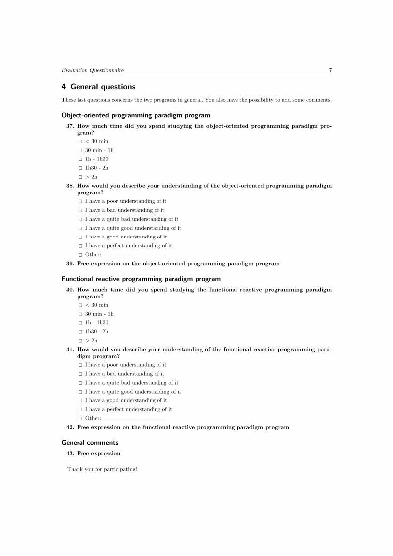
Evaluation Questionnaire 7
4 General questions
These last questions concerns the two programs in general. You also have the possibility to add some comments.
Object-oriented programming paradigm program
37. How much time did you spend studying the object-oriented programming paradigm pro-gram?
2 < 30 min
2 30 min - 1h
2 1h - 1h30
2 1h30 - 2h
2 > 2h
38. How would you describe your understanding of the object-oriented programming paradigmprogram?
2 I have a poor understanding of it
2 I have a bad understanding of it
2 I have a quite bad understanding of it
2 I have a quite good understanding of it
2 I have a good understanding of it
2 I have a perfect understanding of it
2 Other:
39. Free expression on the object-oriented programming paradigm program
Functional reactive programming paradigm program
40. How much time did you spend studying the functional reactive programming paradigmprogram?
2 < 30 min
2 30 min - 1h
2 1h - 1h30
2 1h30 - 2h
2 > 2h
41. How would you describe your understanding of the functional reactive programming para-digm program?
2 I have a poor understanding of it
2 I have a bad understanding of it
2 I have a quite bad understanding of it
2 I have a quite good understanding of it
2 I have a good understanding of it
2 I have a perfect understanding of it
2 Other:
42. Free expression on the functional reactive programming paradigm program
General comments
43. Free expression
Thank you for participating!
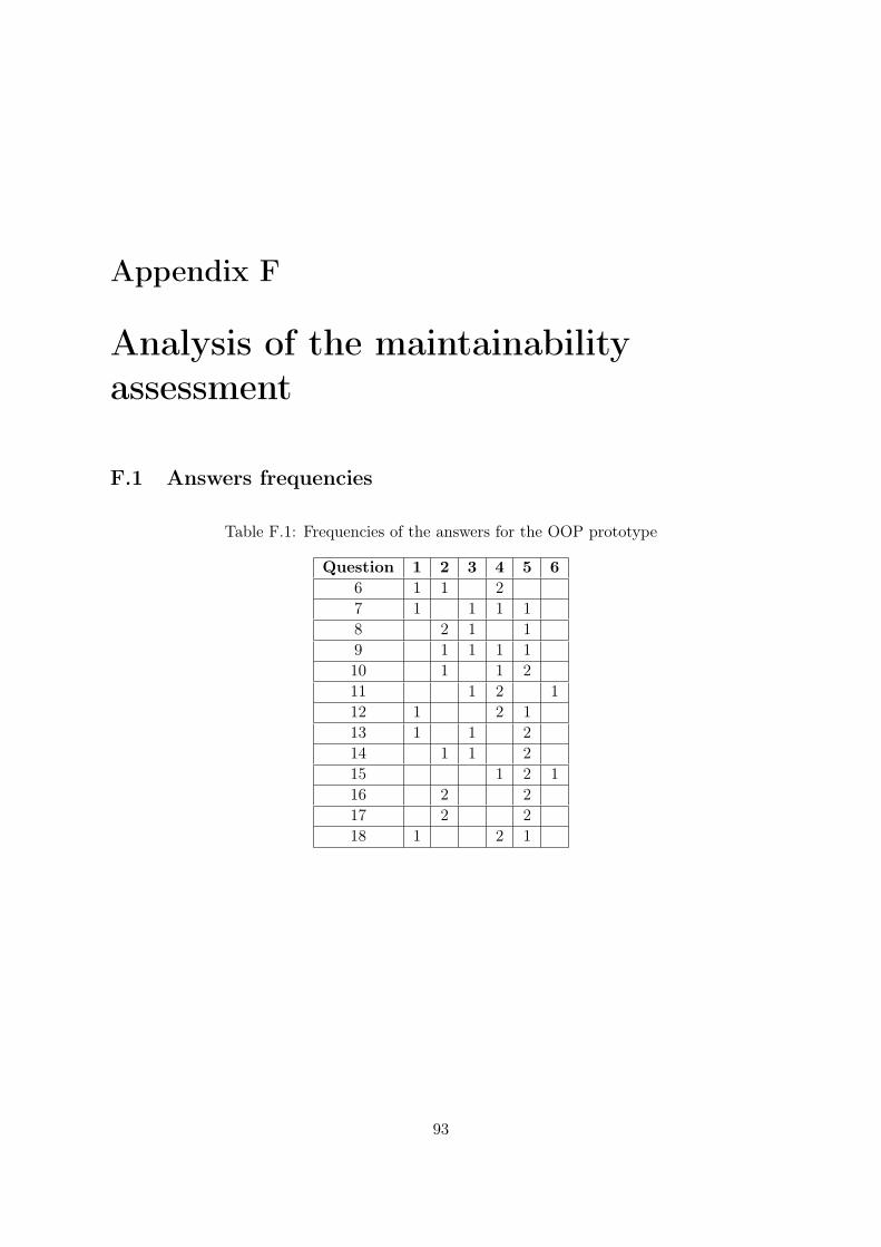
Appendix F
Analysis of the maintainabilityassessment
F.1 Answers frequencies
Table F.1: Frequencies of the answers for the OOP prototype
Question 1 2 3 4 5 66 1 1 27 1 1 1 18 2 1 19 1 1 1 110 1 1 211 1 2 112 1 2 113 1 1 214 1 1 215 1 2 116 2 217 2 218 1 2 1
93
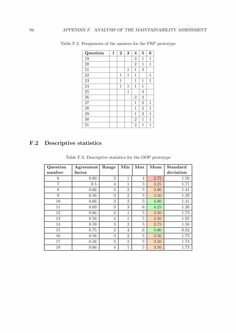
94 APPENDIX F. ANALYSIS OF THE MAINTAINABILITY ASSESSMENT
Table F.2: Frequencies of the answers for the FRP prototype
Question 1 2 3 4 5 619 2 1 120 2 1 121 1 1 222 1 1 1 123 1 1 1 124 1 1 1 125 1 326 2 227 1 2 128 1 2 129 1 2 130 2 1 131 2 1 1
F.2 Descriptive statistics
Table F.3: Descriptive statistics for the OOP prototype
Questionnumber
Agreementfactor
Range Min Max Mean Standarddeviation
6 0.60 3 1 4 2.75 1.507 0.5 4 1 5 3.25 1.718 0.66 3 2 5 3.00 1.419 0.56 3 2 5 3.50 1.2910 0.66 3 2 5 4.00 1.4111 0.69 3 3 6 4.25 1.2612 0.66 4 1 5 3.50 1.7313 0.58 4 1 5 3.50 1.9214 0.59 3 2 5 3.75 1.5015 0.75 2 4 6 5.00 0.8216 0.56 3 2 5 3.50 1.7317 0.56 3 2 5 3.50 1.7318 0.66 4 1 5 3.50 1.73

F.2. DESCRIPTIVE STATISTICS 95
Table F.4: Descriptive statistics for the FRP prototype
Questionnumber
Agreementfactor
Range Min Max Mean Standarddeviation
19 0.69 2 4 6 4.75 0.9620 0.69 2 4 6 4.75 0.9621 0.69 2 3 5 4.25 0.9622 0.5 4 2 6 3.75 1.7123 0.5 4 2 6 4.25 1.7124 0.56 3 2 5 3.50 1.2925 0.88 2 3 5 4.50 1.0026 0.75 1 4 5 4.50 0.5827 0.75 2 4 6 5.00 0.8228 0.75 2 4 6 5.00 0.8229 0.75 2 4 6 5.00 0.8230 0.69 2 4 6 4.75 0.9631 0.69 2 4 6 4.75 0.96

På svenska
Detta dokument hålls tillgängligt på Internet – eller dess framtida ersättare –
under en längre tid från publiceringsdatum under förutsättning att inga extra-
ordinära omständigheter uppstår.
Tillgång till dokumentet innebär tillstånd för var och en att läsa, ladda ner,
skriva ut enstaka kopior för enskilt bruk och att använda det oförändrat för
ickekommersiell forskning och för undervisning. Överföring av upphovsrätten
vid en senare tidpunkt kan inte upphäva detta tillstånd. All annan användning av
dokumentet kräver upphovsmannens medgivande. För att garantera äktheten,
säkerheten och tillgängligheten finns det lösningar av teknisk och administrativ
art.
Upphovsmannens ideella rätt innefattar rätt att bli nämnd som upphovsman i
den omfattning som god sed kräver vid användning av dokumentet på ovan
beskrivna sätt samt skydd mot att dokumentet ändras eller presenteras i sådan
form eller i sådant sammanhang som är kränkande för upphovsmannens litterära
eller konstnärliga anseende eller egenart.
För ytterligare information om Linköping University Electronic Press se
förlagets hemsida http://www.ep.liu.se/
In English
The publishers will keep this document online on the Internet - or its possible
replacement - for a considerable time from the date of publication barring
exceptional circumstances.
The online availability of the document implies a permanent permission for
anyone to read, to download, to print out single copies for your own use and to
use it unchanged for any non-commercial research and educational purpose.
Subsequent transfers of copyright cannot revoke this permission. All other uses
of the document are conditional on the consent of the copyright owner. The
publisher has taken technical and administrative measures to assure authenticity,
security and accessibility.
According to intellectual property law the author has the right to be
mentioned when his/her work is accessed as described above and to be protected
against infringement.
For additional information about the Linköping University Electronic Press
and its procedures for publication and for assurance of document integrity,
please refer to its WWW home page: http://www.ep.liu.se/
© Klervie Toczé