INSTEON Hub: Developer’s Guidecache.insteon.com/developer/2242-222dev-062013-en.pdfOther Documents...
59
INSTEON Hub: Developer’s Guide Version 2.0 © 2005-2013 INSTEON
Transcript of INSTEON Hub: Developer’s Guidecache.insteon.com/developer/2242-222dev-062013-en.pdfOther Documents...

INSTEON Hub: Developer’s Guide
Version 2.0 © 2005-2013 INSTEON

INSTEON Hub: Developer’s Guide
Page i © 2013 INSTEON
Table of Contents
Introduction ................................................................................................................................................. 1
The INSTEON Hub ................................................................................................................................... 1
Other Documents Included by Reference ............................................................................................. 2
INSTEON Developer’s Guide ................................................................................................................ 2
INSTEON Conformance Specification ................................................................................................... 2
INSTEON Command Tables Document ............................................................................................ 2
INSTEON Device Categories and Product Keys Document .............................................................. 2
INSTEON Modem Reference ...................................................................................................................... 3
Software Reference ................................................................................................................................. 3
IM Serial Communication Protocol and Settings ................................................................................... 5
IM Serial Communication Protocol ..................................................................................................... 6
INSTEON HUB communication syntax and examples ............................................................................ 6
Control Commands ................................................................................................................................ 6
Query Commands .................................................................................................................................. 6
Command Syntax .................................................................................................................................. 7
Insteon Commands to send to the Hub for the PLM................................................................... 7
Hub Commands ....................................................................................................................................... 7
Commands that will be in the INSTEON Buffer ..................................................................................... 7
Group Commands .................................................................................................................................. 8
Individual Device Control Commands (Point to Point) ........................................................................... 8
Linking Example: .................................................................................................................................... 8
ID Request Example: ........................................................................................................................... 10
Status Request Example: .................................................................................................................... 10
IM Power-up and Reset States ............................................................................................................ 11
IM Power-up Behavior ...................................................................................................................... 11
IM Factory Reset State..................................................................................................................... 11
IM Serial Commands ........................................................................................................................... 12
IM Serial Command Summary Table ....................................................................................................... 13
IM Serial Command Charts .............................................................................................................. 18
INSTEON Message Handling ....................................................................................................... 19
Send INSTEON Standard or Extended Message ..................................................................... 19
INSTEON Standard Message Received ................................................................................... 22
INSTEON Extended Message Received .................................................................................. 23
Set INSTEON ACK Message Byte ........................................................................................... 24
Set INSTEON ACK Message Two Bytes .................................................................................. 25
Set INSTEON NAK Message Byte ........................................................................................... 26
X10 Message Handling ................................................................................................................ 27
Send X10 .................................................................................................................................. 27
X10 Received ............................................................................................................................ 28
INSTEON ALL-Link Commands ................................................................................................... 29
Send ALL-Link Command ......................................................................................................... 29
ALL-Link Cleanup Failure Report.............................................................................................. 31
ALL-Link Cleanup Status Report .............................................................................................. 32
ALL-Linking Session Management ............................................................................................... 33
Start ALL-Linking....................................................................................................................... 33
Cancel ALL-Linking ................................................................................................................... 34
ALL-Linking Completed ............................................................................................................. 35
ALL-Link Database Management ................................................................................................. 36
Get First ALL-Link Record ........................................................................................................ 36
Get Next ALL-Link Record ........................................................................................................ 37
INSTEON Hub: Developer’s Guide
Page ii © 2013 INSTEON
Get ALL-Link Record for Sender ............................................................................................... 38
ALL-Link Record Response ...................................................................................................... 39
Manage ALL-Link Record ......................................................................................................... 40
IM Status Management ................................................................................................................ 43
Reset the IM .............................................................................................................................. 43
User Reset Detected ................................................................................................................. 44
Get IM Configuration ................................................................................................................. 45
Set IM Configuration ................................................................................................................. 46
Get IM Info ................................................................................................................................ 48
Set Host Device Category ......................................................................................................... 49
RF Sleep ................................................................................................................................... 50
IM Input/Output ............................................................................................................................. 51
Button Event Report .................................................................................................................. 51
LED On ..................................................................................................................................... 52
LED Off ..................................................................................................................................... 53
Cancel Cleanup......................................................................................................................... 54

INSTEON Hub: Developer’s Guide
Page iii © 2013 INSTEON
Revision History
Release Date Author Description
01-30-07 PVD Abstracted from INSTEON Developers Guide.
02-12-07 PVD Added daughter card sections.
02-14-07 PVD Released for proofreading.
03-01-07 PVD More information on the PLM, comparison to PLC.
03-27-07 PVD Fixed bytecount in IM Command 0x62 Send INSTEON Standard or Extended Message.
03-28-07 PVD Added IM Command 0x58 ALL-Link Cleanup Status Report.
03-29-07 PVD Updated explanation of IM Command 0x6F Manage ALL-Link Record.
04-02-07 PVD Updated explanation of IM Commands 0x61 Send ALL-Link Command, 0x56 ALL-Link Cleanup Failure Report, and 0x58 ALL-Link Cleanup Status Report.
04-06-07 PVD IM Command 0x58 ALL-Link Cleanup Status Report also sent when IM interrupts its own Cleanup sequence.
04-17-07 PVD Corrected <X10 Flag> value in IM Commands 0x63 Send X10 and 0x52 X10 Received.
04-19-07 PVD Added page number subscripts to links.
09-14-07 PVD Fixed command number typo for IM Command 0x72 RF Sleep.
10-11-07 PVD Rewrote explanation for IM Command 0x6F Manage ALL-Link Record, enumerated <ALL-Link Record Flags> in IM Command 0x57 ALL-Link Record Response.
Renamed Powerline Modem as PowerLinc Modem.
10-12-07 PVD Added PowerLinc Modem (PLM) Quick Start Guide section
1-18-08 JTL Updated Set IM command to include that if Bit 3=1, the interface will NAK serial commands if the it is busy processing an INSTEON command.
3-16-12 BJV Added IM commands
7-23-12 BJV Added Hub communication

INSTEON Hub: Developer’s Guide
Page iv © 2013 INSTEON
Legal Information
Terms of Use This INSTEON Hub Developer’s Guide is supplied to you by SmartLabs, Inc. (SmartLabs) in consideration of your agreement to the following terms. Your use or installation of this INSTEON Hub Developer’s Guide constitutes acceptance of these terms. If you do not agree with these terms, please do not use or install this INSTEON Hub Developer’s Guide.
In consideration of your agreement to abide by the following terms, and subject to these terms, SmartLabs grants you a personal, non-exclusive license, under SmartLabs’ intellectual property rights in this INSTEON Hub Developer’s Guide, to use this INSTEON Hub Developer’s Guide; provided that no license is granted herein under any patents that may be infringed by your works, modifications of works, derivative works or by other works in which the information in this INSTEON Hub Developer’s Guide may be incorporated. No names, trademarks, service marks or logos of SmartLabs, Inc. or INSTEON may be used to endorse or promote products derived from the INSTEON Hub Developer’s Guide without specific prior written permission from SmartLabs, Inc. Except as expressly stated herein, no other rights or licenses, express or implied, are granted by SmartLabs and nothing herein grants any license under any patents except claims of SmartLabs patents that cover this INSTEON Hub Developer’s Guide as originally provided by SmartLabs, and only to the extent necessary to use this INSTEON Hub Developer’s Guide as originally provided by SmartLabs. SmartLabs provides this INSTEON Hub Developer’s Guide on an "AS IS" basis.
SMARTLABS MAKES NO WARRANTIES, EXPRESS OR IMPLIED, INCLUDING WITHOUT LIMITATION THE IMPLIED WARRANTIES OF NON-INFRINGEMENT, MERCHANTABILITY AND FITNESS FOR A PARTICULAR PURPOSE, REGARDING THIS INSTEON HUB DEVELOPER’S GUIDE OR ITS USE, ALONE OR IN COMBINATION WITH ANY PRODUCT.
IN NO EVENT SHALL SMARTLABS BE LIABLE FOR ANY SPECIAL, INDIRECT, INCIDENTAL OR CONSEQUENTIAL DAMAGES (INCLUDING, BUT NOT LIMITED TO, PROCUREMENT OF SUBSTITUTE GOODS OR SERVICES; LOSS OF USE, DATA, OR PROFITS; OR BUSINESS INTERRUPTION) ARISING IN ANY WAY OUT OF THE USE, REPRODUCTION, MODIFICATION AND/OR DISTRIBUTION OF THIS INSTEON HUB DEVELOPER’S GUIDE, HOWEVER CAUSED AND WHETHER UNDER THEORY OF CONTRACT, TORT (INCLUDING NEGLIGENCE), STRICT LIABILITY OR OTHERWISE, EVEN IF SMARTLABS HAS BEEN ADVISED OF THE POSSIBILITY OF SUCH DAMAGE.
Trademarks and Patents SmartLabs, INSTEON, Dual Mesh, BiPHY, ALL-Link, PowerLinc, LampLinc, SwitchLinc, SmartLabs Device Manager, Home Network Language, and Plug-n-Tap are trademarks of SmartLabs, Inc.
INSTEON networking technology is covered by pending U.S. and foreign patents.
Copyright © Copyright 2005 - 2013 INSTEON 16542 Millikan Ave., Irvine, CA 92606-5027; 866-243-8022 www.insteon.com. All rights reserved.

INSTEON Hub: Developer’s Guide
Page 1 © 2013 INSTEON
Introduction This INSTEON Hub Developer’s Guide is for users of INSTEON Modem chips, such as the IN2680A Powerline Modem Interface or the IN2682A RF Modem Interface, and also for purchasers of the INSTEON PowerLinc™ Modem (PLM) module.
The information in this document is excepted from the INSTEON Developer’s Guide2, which purchasers of an INSTEON Software Development Kit may download from http://code.insteon.com.
The INSTEON Hub
The INSTEON Hub is an INSTEON-to-Ethernet Bridge module that plugs into a power outlet and also has a ethernet port that you connect to your network. It uses an IN2680A Powerline Modem chip that offers a simple set of ASCII IM Serial Commands12 for interacting with INSTEON devices.
The Hub uses a daughter board to implement serial communications with the host. Daughter boards interface to the PLM’s main board via an 8-pin connector using TTL-level serial communications.
INSTEON Hub: Developer’s Guide
Page 2 © 2013 INSTEON
Other Documents Included by Reference
This INSTEON Hub Developer’s Guide contains information abstracted from the comprehensive INSTEON Developer’s Guide, 2
nd Edition.
Although the full INSTEON Developer’s Guide is largely self-contained, there are aspects of INSTEON technology, such as listings of INSTEON Commands, INSTEON Device Categories, and INSTEON Product Keys, that require continuous updating as developers create new INSTEON products. Accordingly, SmartLabs maintains separate documents for that kind of information.
All of the documents listed in this section are available for downloading at http://code.insteon.com.
INSTEON Developer’s Guide
The book-length INSTEON Developer’s Guide, 2nd
Edition is the primary source for the information contained in this (much shorter) INSTEON Hub Developer’s Guide. Some links in this document refer to information found there. Developers who purchase an INSTEON Software Developer’s Kit may download the INSTEON Developer’s Guide from http://code.insteon.com.
INSTEON Conformance Specification
The INSTEON Conformance Specification identifies those aspects of INSTEON that assure interoperability with other INSTEON products. The Conformance Spec assumes that readers have already gained familiarity with INSTEON technology by reading the INSTEON Developer’s Guide.
INSTEON Command Tables Document
The current tables of INSTEON Commands are contained in a separate document titled INSTEON Command Tables, which is integral to both the INSTEON Conformance Specification and the INSTEON Developer’s Guide.
The filename for that document is INSTEON Command Tables yyyymmddx.doc, where yyyy is the year, mm is the month, dd is the day, and x is a daily version letter beginning with a. Be sure to refer to the document with the latest date.
INSTEON Device Categories and Product Keys Document
The current table of INSTEON Device Categories (DevCats), Subcategories (SubCats), and INSTEON Product Keys (IPKs) is contained in a separate document titled INSTEON Device Categories and Product Keys, which is also integral to both the INSTEON Conformance Specification and the INSTEON Developer’s Guide.
The filename for that document is INSTEON DevCats and Product Keys yyyymmddx.doc, where yyyy is the year, mm is the month, dd is the day, and x is a daily version letter beginning with a. Be sure to refer to the document with the latest date.

INSTEON Hub: Developer’s Guide
Page 3 © 2013 INSTEON
INSTEON Modem Reference
Software Reference
INSTEON Modem (IM) chips and the SmartLabs Hub offer developers a simple, robust interface to an INSTEON network.
INSTEON Hubs provide a simpler interface to many of the low-level IBIOS Serial Commands implemented in the SmartLabs Hub described in the INSTEON Developer’s Guide2, but they also handle ALL-Linking, ALL-Link Database management, ALL-Link Cleanup messages, X10 powerline interfacing, and message acknowledgement. The RS232 serial interface to the host is similar to that of the PLC.
In This Section

INSTEON Hub: Developer’s Guide
Page 4 © 2013 INSTEON
IM Serial Communication Protocol and Settings5 Describes the serial communication protocol
IM Power-up and Reset States11 Explains what happens when you power up the IM or reset it.
IM Serial Commands12 Lists the IM Serial Commands and describes what they do, in a single table and individual charts grouped by functionality.

INSTEON Hub: Developer’s Guide
Page 5 © 2013 INSTEON
IM Serial Communication Protocol and Settings
In This Section
IM Serial Communication Protocol6 Gives the protocol for communicating serially with an INSTEON Modem.
INSTEON Hub: Developer’s Guide
Page 6 © 2013 INSTEON
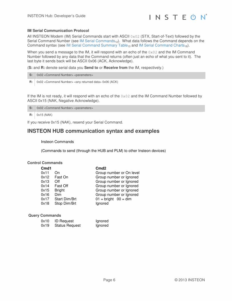
IM Serial Communication Protocol
All INSTEON Modem (IM) Serial Commands start with ASCII 0x02 (STX, Start-of-Text) followed by the
Serial Command Number (see IM Serial Commands12). What data follows the Command depends on the Command syntax (see IM Serial Command Summary Table13 and IM Serial Command Charts18).
When you send a message to the IM, it will respond with an echo of the 0x02 and the IM Command
Number followed by any data that the Command returns (often just an echo of what you sent to it). The last byte it sends back will be ASCII 0x06 (ACK, Acknowledge).
(S: and R: denote serial data you Send to or Receive from the IM, respectively.)
S: 0x02 <Command Number> <parameters>
R: 0x02 <Command Number> <any returned data> 0x06 (ACK)
If the IM is not ready, it will respond with an echo of the 0x02 and the IM Command Number followed by
ASCII 0x15 (NAK, Negative Acknowledge).
S: 0x02 <Command Number> <parameters>
R: 0x15 (NAK)
If you receive 0x15 (NAK), resend your Serial Command.
INSTEON HUB communication syntax and examples
Insteon Commands
(Commands to send (through the HUB and PLM) to other Insteon devices)
Control Commands
Cmd1 Cmd2 0x11 On Group number or On level 0x12 Fast On Group number or Ignored
0x13 Off Group number or Ignored 0x14 Fast Off Group number or Ignored 0x15 Bright Group number or Ignored 0x16 Dim Group number or Ignored 0x17 Start Dim/Brt 01 = bright 00 = dim 0x18 Stop Dim/Brt Ignored
Query Commands
0x10 ID Request Ignored 0x19 Status Request Ignored

INSTEON Hub: Developer’s Guide
Page 7 © 2013 INSTEON
Command Syntax
<ip address>/X?YYYYY=I=X Where X is a number. All the examples show either a 0 (zero) or a 1 (one). The YYYY is the command bytes. The suffix is always this: = I (letter I) = Number 0 (zero): means a “short form” command that doesn’t include a destination and flags byte, 3: the full Insteon command as you would send to the Insteon modem. For a group: http://172.16.1.34/0?1101=I=0 where 0x11 is the command and 01 is the group. (URL is an example of intranet) For a group: http://bobbieshome.myhouse:8000/0?13182=I=0 where 0x13 is the command and 182 is the group. (URL is an example of internet using getmyip.com to track Dynamic DNS for the hub) (Note the interesting combination of Hex and decimal numbers i.e. 13 182) For a device: http://172.16.1.34/3?02620102030F117F=I=3 where 010203 is the device ID and 0F is the flags byte and 0x11 is the command and 7F is the on level (1/2 brightness).
Insteon Commands to send to the Hub for the PLM
0x09 Enter Linking mode Group Number 0x0A Enter UnLinking Group Number 0x08 Cancels Un/Linking Ignored http://172.16.1.34/0?0901=I=0 where 0x09 is the command and 01 is the group. http://172.16.1.34/0?0A239=I=0 where 0x0A is the command and 239 is the group. http://172.16.1.34/0?08=I=0 where 0x08 is the command.
Hub Commands
http://172.16.1.34/1?XB=M=1 Clear Insteon buffer
Commands that will be in the INSTEON Buffer
The INSTEON buffer can be read from “/buffstatus.xml” and can hold up to 100 characters or 50 hex bytes. http://172.16.1.34/buffstatus.xml

INSTEON Hub: Developer’s Guide
Page 8 © 2013 INSTEON
Group Commands
026101110106 Echo of your Command: Turn group 1 On 026101110115 Response if you tried to turn on an empty group 025009316B09D682611101 Ack from a device (Clean-up) 09316B ID of a device in your group 09D682 ID of the Hub 61 Flags byte 20 = Ack + 40 = Group + 1 = Hop count 025806 Group command completed Ok 025815 Group command quit early Ok
Individual Device Control Commands (Point to Point)
Example of turning on device 0E7986 to Full On Send:
http://172.16.1.34/3?02620E79860F11FF=I=3 The Buffer will have
02620E79860F11FF0602500E798609D6822B11FF Send and PLM Echoes back to the buffer:
0262 Pass through Command to PLM 0E7986 Device ID to Control 0F Flags Byte (Constant) 11 CMD1 (On) FF CMD2 (Brightness level)
PLM Adds: 06 PLM Says got it
Once the Device responds (Could be ¼ of a second but not>3 secs) 0250 From PLM Insteon Received 0E7986 From this device 09D682 To (ID of PLM/Hub) 2B 20 = ACK + B = hop count 11 CMD1 The command the device received FF Cmd2 The On level it will go to
Note: The timing will be such that even if you see the 0250 in the buffer you are not guaranteed
that the rest of the data is in the buffer yet. Pretend example of a timing issue to resolve. 2:01.1 buffer has Null (just emptied it) 2:02.2 send http://172.16.1.34/3?02620102030F117F=I=3 2:03.0 ask for the buffer 2:03.5 get 02620E79860F11FF0602500E7 2:03.7 ask for the buffer again 2:03.9 get 02620E79860F11FF0602500E798609D6822B11FF In a group command, the buffer will quickly wrap with the clean-ups so searching for the 0258 is a
little tricky since that is also a valid Partial Insteon ID.
Linking Example:

INSTEON Hub: Developer’s Guide
Page 9 © 2013 INSTEON
Send go into Linking mode group 137. http://172.16.1.34/0?09137=I=0
The PLM echoes and adds an 06 0264018906 (0264 linking command 01 controller and group 0x89)
Press and hold the button on the new device 02640101060253010108B6EA010195
0264010106 Left in the buffer from go into linking mode 0253 Linking completed 01 Device can be a controller (00 and FF are valid) 01 Group 08B6EA ID of device 01 Device Category (01 = Dimmer) 01 Device SubCat (01 = SwitchLinc) 95 Firmware Version of New device

INSTEON Hub: Developer’s Guide
Page 10 © 2013 INSTEON
ID Request Example:
http://172.16.1.34/3?02620E79860F1000=I=3
The buffer will have 02620E79860F10000602500E798609D6822B100002500E798601009C8B0100
0262 Pass through Command to PLM 0E7986 Insteon ID 0F Flags 10 CMD1
00 CMD2 06 0250 Insteon Message 0E7986 From 09D682 To 2B Flags Byte 20 = ACK + B = Hop count 10 Echo CMD1 00 Echo CMD2 0250 Insteon Message (about 1 sec later) 0E7986 From 01 Cat (01 = Dimmer) 00 (SubCat) (00 = LampLinc) 9C Firmware version 8B Flags Byte 80 = Broadcast + B = hop count 01 CMD1 01 = ID Request 00 CMD2 00 = Ignore
Status Request Example:
http://172.16.1.34/3?02620E79860F1900=I=3
The buffer will have 02620E79860F19000602500E798609D6822B03FF
0262 Pass Through 0E7986 ID 0F Flags 19 CMD1 Status Request 00 CMD2 06 0250 Insteon Received 0E7986 From 09D682 To 2B 20 = ACK + B = Hop Count 03 03 is the Delta…gets changed every time EE is changed (Ignore) FF Current On Level could be 00 – FF
Note: Status Request returns Info in the ACK while ID request generates

INSTEON Hub: Developer’s Guide
Page 11 © 2013 INSTEON
IM Power-up and Reset States
This section describes the IM Power-up Behavior11 and the IM Factory Reset State11.
IM Power-up Behavior
The table below shows the state of the IM when it powers up. Holding down the SET Button while powering up will cause a factory reset.
LED Indication Meaning
LED on steadily The IM detected an external EEPROM (up to 32 Kb) for storage of database links. Effective with product revisions 2.75 or greater, a 128Kb EEPROM is included for storage of database links
LED blinks six times The IM did not detect an external EEPROM, so it will use the internal EEPROM in the processor chip. A maximum of 31 ALL-Links are permitted. An attempt to add a 32
nd ALL-Link will result in the 31
st being erased.
LED off The user pressed and held the IM’s SET button for 10 seconds while powering up, causing the IM to perform a factory reset and go into the IM Factory Reset State11. At the conclusion of the reset, the IM’s LED will give one of the two indications above. You will also receive a User Reset Detected44 message from the IM.
IM Factory Reset State
Resetting the IM to its factory default condition by holding down the SET Button for ten seconds while powering it up or by sending it a Reset the IM43 Command puts it into the following state:
IM Resource Factory Reset State
ALL-Link Database Erased (set to all zeros).
Host Device Category, Device Subcategory, Firmware Version
Set to the original DevCat (0x03), SubCat (0x05), and firmware version hard-coded into the IM’s firmware at the factory.
IM Configuration Flags
Cleared (set to all zeros).

INSTEON Hub: Developer’s Guide
Page 12 © 2013 INSTEON
IM Serial Commands
The IM Serial Command set is a simple but complete interface between a host application and an INSTEON network. For example, a microcontroller in a thermostat could use an INSTEON Powerline Modem chip to send and receive messages to other INSTEON or X10 devices on the home’s powerline.
In this section, the IM Serial Commands are presented twice, once as a summary table, and again as a series of charts grouped by functionality.
In This Section
IM Serial Command Summary Table13 Describes all of the IM Serial Commands in table form ordered by Command Number.
IM Serial Command Charts18 Describes all of the IM Serial Commands using individual charts for each Command, grouped by functionality.

INSTEON Hub: Developer’s Guide
Page 13 © 2013 INSTEON
IM Serial Command Summary Table This table lists all of the Modem Serial Commands supported by INSTEON powerline or RF modem chips.
Code Gives the hexadecimal number of the IM Serial Command. Note that IM Commands sent by an IM to the host begin at 0x50 and IM Commands sent by the host to an IM begin at 0x60.
Command Gives the name of the IM Serial Command as a link to the complete explanation of the Command in the IM Serial Command Charts18.
Format Gives the syntax of the IM Serial Command, including any parameters.
S: and R: denote serial data you Send to or Receive from the IM, respectively. See IM Serial Communication Protocol6 for more information.
All IM Serial Commands start with ASCII 0x02 (STX, Start-of-Text) followed by the Serial Command Number.
All fields in this table contain only one byte, except as noted.
INSTEON Modem Serial Commands
Commands Sent from an IM to the Host
Code Command Format
0x50 INSTEON Standard Message Received22
R: 0x02 0x50
<INSTEON Standard message (9 bytes)>
0x51 INSTEON Extended Message Received23
R: 0x02 0x51
<INSTEON Extended message (23 bytes)>
0x52 X10 Received28 R: 0x02 0x52
<Raw X10> <X10 Flag>
0x53 ALL-Linking Completed35 R: 0x02 0x53
<0x00 (IM is Responder) | 0x01 (IM is Controller | 0xFF Link Deleted)>
<ALL-Link Group>
<ID high byte> <ID middle byte> <ID low byte>
<Device Category> <Device Subcategory> <0xFF | Firmware Revision>
0x54 Button Event Report51 R: 0x02 0x54 <0x02>
IM’s SET Button tapped
R: 0x02 0x54 <0x03>
IM’s SET Button held
R: 0x02 0x54 <0x04>
IM’s SET Button released after hold
R: 0x02 0x54 <0x12>
IM’s Button 2 tapped
R: 0x02 0x54 <0x13>
IM’s Button 2 held
R: 0x02 0x54 <0x14>
IM’s Button 2 released after hold
R: 0x02 0x54 <0x22>
IM’s Button 3 tapped
R: 0x02 0x54 <0x23>
IM’s Button 3 held
R: 0x02 0x54 <0x24>
IM’s Button 3 released after hold
0x55 User Reset Detected44 R: 0x02 0x55
User pushed and held IM’s SET Button on power up

INSTEON Hub: Developer’s Guide
Page 14 © 2013 INSTEON
0x56 ALL-Link Cleanup Failure Report31
R: 0x02 0x56 <0x01>
<ALL-Link Group>
<ID high byte> <ID middle byte> <ID low byte>
0x57 ALL-Link Record Response39 R: 0x02 0x57
<ALL-Link Record Flags>
<ALL-Link Group>
<ID high byte> <ID middle byte> <ID low byte>
<Link Data 1> <Link Data 2> <Link Data 3>
0x58 ALL-Link Cleanup Status Report32
R: 0x02 0x58 <0x06>
ALL-Link Cleanup sequence completed
R: 0x02 0x58 <0x15>
ALL-Link Cleanup sequence aborted due to INSTEON traffic
0x59 Database Record Found32 R: 0x02 0x59 <Database Address high byte>
<Database Address low byte (low nibble should be 0xF | 0x8)>
<ALL-Link Record Flags>
<ALL-Link Group>
<ID high byte> <ID middle byte> <ID low byte>
<Link Data 1> <Link Data 2> <Link Data 3>
Commands Sent from the Host to an IM
0x60 Get IM Info48 S: 0x02 0x60
R: 0x02 0x60
<ID high byte> <ID middle byte> <ID low byte>
<Device Category> <Device Subcategory> <Firmware Revision>
<0x06>
0x61 Send ALL-Link Command29 S: 0x02 0x61
<ALL-Link Group>
<ALL-Link Command>
<0xFF | 0x00>
R: 0x02 0x61
<ALL-Link Group>
<ALL-Link Command>
<0xFF | 0x00>
<0x06>
0x62 Send INSTEON Standard or Extended Message19
S: 0x02 0x62
<INSTEON Standard message (6 bytes, excludes From Address) |
INSTEON Extended message (20 bytes, excludes From Address)>
R: 0x02 0x62
<INSTEON Standard message (6 bytes, excludes From Address) |
INSTEON Extended message (20 bytes, excludes From Address)>
<0x06>
0x63 Send X1027 S: 0x02 0x63
<Raw X10> <X10 Flag>
R: 0x02 0x63
<Raw X10> <X10 Flag>
<0x06>
0x64 Start ALL-Linking33 S: 0x02 0x64
<0x00 (IM is Responder) | 0x01 (IM is Controller) |
0x03 (IM is either) | 0xFF (Link Deleted)
bit2 set = use Set Database Link Data for next Link>
<ALL-Link Group>
R: 0x02 0x64
<0x00 (IM is Responder) | 0x01 (IM is Controller) |
0x03 (IM is either) | 0xFF (Link Deleted)>
<ALL-Link Group>
<0x06>
0x65 Cancel ALL-Linking34 S: 0x02 0x65
R: 0x02 0x65
<0x06>
0x66 Set Host Device Category49 S: 0x02 0x66
<Device Category> <Device Subcategory> <0x00 | Firmware Revision>

INSTEON Hub: Developer’s Guide
Page 15 © 2013 INSTEON
R: 0x02 0x66
<Device Category> <Device Subcategory> <0x00 | Firmware Revision>
<0x06>
0x67 Reset the IM43 S: 0x02 0x67
R: 0x02 0x67
<0x06>
0x68 Set INSTEON ACK Message Byte24
S: 0x02 0x68
<Command 2 Data>
R: 0x02 0x68
<Command 2 Data>
<0x06>
0x69 Get First ALL-Link Record36 S: 0x02 0x69
R: 0x02 0x69
<0x06>
0x6A Get Next ALL-Link Record37 S: 0x02 0x6A
R: 0x02 0x6A
<0x06>
0x6B Set IM Configuration46 S: 0x02 0x6B
<IM Configuration Flags>
R: 0x02 0x6B
<IM Configuration Flags>
<0x06>
0x6C Get ALL-Link Record for Sender38
S: 0x02 0x6C
R: 0x02 0x6C
<0x06>
0x6D LED On52 S: 0x02 0x6D
R: 0x02 0x6D
<0x06>
0x6E LED Off53 S: 0x02 0x6E
R: 0x02 0x6E
<0x06>
0x6F Manage ALL-Link Record40 S: 0x02 0x6F
<Control Flags>
<ALL-Link Record Flags>
<ALL-Link Group>
<ID high byte> <ID middle byte> <ID low byte>
<Link Data 1> <Link Data 2> <Link Data 3>
R: 0x02 0x6F
<Control Flags>
<ALL-Link Record Flags>
<ALL-Link Group>
<ID high byte> <ID middle byte> <ID low byte>
<Link Data 1> <Link Data 2> <Link Data 3>
<0x06>
0x70 Set INSTEON NAK Message Byte26
S: 0x02 0x70
<Command 2 Data>
R: 0x02 0x70
<Command 2 Data>
<0x06>
0x71 Set INSTEON ACK Message Two Bytes25
S: 0x02 0x71
<Command 1 Data>
<Command 2 Data>
R: 0x02 0x71
<Command 1 Data>
<Command 2 Data>
<0x06>
0x72 RF Sleep50 S: 0x02 0x72
R: 0x02 0x72
<0x06>
0x73 Get IM Configuration45 S: 0x02 0x73

INSTEON Hub: Developer’s Guide
Page 16 © 2013 INSTEON
R: 0x02 0x73
<IM Configuration Flags>
<Spare 1>
<Spare 2>
<0x06>

INSTEON Hub: Developer’s Guide
Page 17 © 2013 INSTEON
These commands added after initial release:
INSTEON Modem Serial Commands
Commands Sent from the Host to an IM
Code Command Format
0x74 Cancel Cleanup22 S: 0x02 0x74
R: 0x02 0x74
<0x06>
0x75 Read 8 bytes from Database23
S: 0x02 0x75 <Database Address high byte>
<Database Address low byte (low nibble should be 0xF | 0x8)>
R: 0x02 0x75 <Database Address high byte>
<Database Address low byte (low nibble should be 0xF | 0x8)>
<0x06>
<Database Record Found Response (12 bytes)>
0x76 Write 8 bytes to Database28 S: 0x02 0x76 <Database Address high byte>
<Database Address low byte (low nibble should be 0xF | 0x8)>
<ALL-Link Record Flags>
<ALL-Link Group>
<ID high byte> <ID middle byte> <ID low byte>
<Link Data 1> <Link Data 2> <Link Data 3>
R: 0x02 0x76 <Database Address high byte>
<Database Address low byte (low nibble should be 0xF | 0x8)>
<ALL-Link Record Flags>
<ALL-Link Group>
<ID high byte> <ID middle byte> <ID low byte>
<Link Data 1> <Link Data 2> <Link Data 3> <0x06>
0x77 Beep35 S: 0x02 0x77
R: 0x02 0x77 <0x06>
IM will beep
0x78 Set Status51 S: 0x02 0x78 <Status>
R: 0x02 0x78 <Status>
<0x06>
IM will report Status in cmd2 of a direct Status Request command (0x19)
RF Modem only commands
0x79 Set Database Link Data for next Link44
S: 0x02 0x79 <Link Data 1> <Link Data 2> <Link Data 3>
(Note: bit 2 must be set in Start All-Linking command to use Link Data)
R: 0x02 0x79 <Link Data 1> <Link Data 2> <Link Data 3>
<0x06>
0x7A Set Application Retries for New Links31
S: 0x02 0x7A <Number of Application Retries for new links>
R: 0x02 0x7A <Number of Application Retries for new links>
<0x06>
0x7B Set RF Frequency Offset39 S: 0x02 0x7B <RF Frequency Offset
(increase frequency from least offset: 0x00 up to most offset: 0x7F;
decrease frequency from least offset: 0xFF down to most offset: 0x8F)>
R: 0x02 0x7B <RF Frequency Offset>
<0x06>
0x7C Set Acknowledge for TempLinc command
S: 0x02 0x7C <XXXXXXXXXXXXXXXX>
R: 0x02 0x7C <XXXXXXXXXXXXXXXX>
<0x06>

INSTEON Hub: Developer’s Guide
Page 18 © 2013 INSTEON
IM Serial Command Charts
The following charts describe the IM Commands individually in a chart format, grouped by functionality. These are the same IM Commands as in the IM Serial Command Summary Table13, which is ordered by Command Number.
Note that IM Commands sent by an IM to the host begin at 0x50 and IM Commands sent by the host to an IM begin at 0x60. When the host sends an IM Command to an IM, the IM will respond with a message according to the IM Serial Communication Protocol6.
In This Section
INSTEON Message Handling19 Commands for sending and receiving INSTEON messages.
X10 Message Handling27 Commands for sending and receiving X10 messages.
INSTEON ALL-Link Commands29 Commands for sending ALL-Link Commands with automatic handling of ALL-Link Cleanup Commands.
ALL-Linking Session Management33 Commands for creating ALL-Links between an IM and other INSTEON devices.
ALL-Link Database Management36 Commands for managing ALL-Link Records in the IM’s ALL-Link Database.
IM Status Management43 Commands for resetting and configuring the IM.
IM Input/Output51 Commands for managing the IM’s SET Button and LED.

INSTEON Hub: Developer’s Guide
Page 19 © 2013 INSTEON
INSTEON Message Handling
Send INSTEON Standard or Extended Message
This Command lets you send either a Standard-length or an Extended-length INSTEON message, depending only on what kind of INSTEON message you include in the body of the Command.
Send INSTEON Standard-length Message
Send INSTEON Standard-length Message (0x62)
What it does Allows you to send a raw Standard-length INSTEON message.
What you send 8 bytes.
What you’ll get 9 bytes.
LED indication None.
Related Commands IM 0x50 INSTEON Standard Message Received22
IM 0x51 INSTEON Extended Message Received23
Command Sent from Host to IM
Byte Value Meaning
1 0x02 Start of IM Command
2 0x62 IM Command Number
3 <To Address high> The high byte of the INSTEON ID of the message addressee.
4 <To Address middle> The middle byte of the INSTEON ID of the message addressee.
5 <To Address low> The low byte of the INSTEON ID of the message addressee.
6 <Message Flags> The INSTEON message flags indicating message type and hops.
Extended Message Flag (bit 4) is 0
7 <Command 1> INSTEON Command 1 for the addressee to execute
8 <Command 2> INSTEON Command 2 for the addressee to execute
Message Returned by IM to Host
Byte Value Meaning
1 0x02 Echoed Start of IM Command
2 0x62 Echoed IM Command Number
3 <To Address high> Echoed <To Address high>
4 <To Address middle> Echoed <To Address middle>
5 <To Address low> Echoed <To Address low>
6 <Message Flags> Echoed <Message Flags>
Extended Message Flag (bit 4) is 0
7 <Command 1> Echoed <Command 1>
8 <Command 2> Echoed <Command 2>
9 <ACK/NAK> 0x06 (ACK) if the IM executed the Command correctly
0x15 (NAK) if an error occurred
Notes
The From Address is not required because the IM will automatically insert its own INSTEON ID into the message.
For more information on INSTEON Commands and the latest Command set, please download the current INSTEON Command Tables Document2 from http://code.insteon.com.

INSTEON Hub: Developer’s Guide
Page 20 © 2013 INSTEON
Send INSTEON Extended-length Message
Send INSTEON Extended-length Message (0x62)
What it does Allows you to send a raw Extended-length INSTEON message.
What you send 22 bytes.
What you’ll get 23 bytes.
LED indication None.
Related Commands IM 0x50 INSTEON Standard Message Received22
IM 0x51 INSTEON Extended Message Received23
Command Sent from Host to IM
Byte Value Meaning
1 0x02 Start of IM Command
2 0x62 IM Command Number
3 <To Address high> The high byte of the INSTEON ID of the message addressee.
4 <To Address middle> The middle byte of the INSTEON ID of the message addressee.
5 <To Address low> The low byte of the INSTEON ID of the message addressee.
6 <Message Flags> The INSTEON message flags indicating message type and hops.
Extended Message Flag (bit 4) is 1
7 <Command 1> INSTEON Command 1 for the addressee to execute
8 <Command 2> INSTEON Command 2 for the addressee to execute
9 <User Data 1> Extended message data
10 <User Data 2> Extended message data
11 <User Data 3> Extended message data
12 <User Data 4> Extended message data
13 <User Data 5> Extended message data
14 <User Data 6> Extended message data
15 <User Data 7> Extended message data
16 <User Data 8> Extended message data
17 <User Data 9> Extended message data
18 <User Data 10> Extended message data
19 <User Data 11> Extended message data
20 <User Data 12> Extended message data
21 <User Data 13> Extended message data
22 <User Data 14> Extended message data
Message Returned by IM to Host
Byte Value Meaning
1 0x02 Echoed Start of IM Command
2 0x62 Echoed IM Command Number
3 <To Address high> Echoed <To Address high>
4 <To Address middle> Echoed <To Address middle>
5 <To Address low> Echoed <To Address low>
6 <Message Flags> Echoed <Message Flags>
Extended Message Flag (bit 4) is 1
7 <Command 1> Echoed <Command 1>
8 <Command 2> Echoed <Command 2>
9 <User Data 1> Echoed Extended message data
10 <User Data 2> Echoed Extended message data
11 <User Data 3> Echoed Extended message data
12 <User Data 4> Echoed Extended message data
13 <User Data 5> Echoed Extended message data
14 <User Data 6> Echoed Extended message data
15 <User Data 7> Echoed Extended message data
16 <User Data 8> Echoed Extended message data
17 <User Data 9> Echoed Extended message data
18 <User Data 10> Echoed Extended message data

INSTEON Hub: Developer’s Guide
Page 21 © 2013 INSTEON
19 <User Data 11> Echoed Extended message data
20 <User Data 12> Echoed Extended message data
21 <User Data 13> Echoed Extended message data
22 <User Data 14> Echoed Extended message data
23 <ACK/NAK> 0x06 (ACK) if the IM executed the Command correctly
0x15 (NAK) if an error occurred
Notes
The From Address is not required because the IM will automatically insert its own INSTEON ID into the message.
For more information on INSTEON Commands and the latest Command set, please download the current INSTEON Command Tables Document2 from http://code.insteon.com.

INSTEON Hub: Developer’s Guide
Page 22 © 2013 INSTEON
INSTEON Standard Message Received
INSTEON Standard Message Received (0x50)
What it does Informs you of an incoming Standard-length INSTEON message.
When you’ll get this A Standard-length INSTEON message is received from either a Controller or Responder that you are ALL-Linked to.
What you’ll get 11 bytes.
LED indication The LED will blink during INSTEON reception.
Related Commands IM 0x51 INSTEON Extended Message Received23
IM 0x52 X10 Received28
Message Sent from IM to Host
Byte Value Meaning
1 0x02 Start of IM Command
2 0x50 IM Command Number
3 <From Address high> The high byte of the INSTEON ID of the message originator.
4 <From Address middle> The middle byte of the INSTEON ID of the message originator.
5 <From Address low> The low byte of the INSTEON ID of the message originator.
6 <To Address high> The high byte of the INSTEON ID of the message addressee.
If the message is an ALL-Link Broadcast (bits 7 and 6 of the <Message Flags> byte are set) then this will be 0.
7 <To Address middle> The middle byte of the INSTEON ID of the message addressee.
If the message is an ALL-Link Broadcast (bits 7 and 6 of the <Message Flags> byte are set) then this will be 0.
8 <To Address low> The low byte of the INSTEON ID of the message addressee.
If the message is an ALL-Link Broadcast (bits 7 and 6 of the <Message Flags> byte are set) then this will indicate the ALL-Link Group Number.
9 <Message Flags> The INSTEON message flags indicating message type and hops.
10 <Command 1> INSTEON Command 1 field of the message.
11 <Command 2> INSTEON Command 2 field of the message.
This byte contains the ALL-Link Group Number of the ALL-Link Broadcast when either bit 6 of the <Message Flags> byte is set (ALL-Link Cleanup) or bits 6 and 5 of the <Message Flags> byte are set (ALL-Link Cleanup ACK).
Notes
This is the same as IM 0x51 INSTEON Extended Message Received23, except that there is no <User Data>.
Normally, the IM will only send the host INSTEON messages that are explicitly addressed to the IM or that are from devices that the IM is ALL-Linked to. This behavior can be modified—see the About Monitor Mode46 note in the Set IM Configuration46 chart for more information.
For more information on INSTEON Commands and the latest Command set, please download the current INSTEON Command Tables Document2 from http://code.insteon.com.

INSTEON Hub: Developer’s Guide
Page 23 © 2013 INSTEON
INSTEON Extended Message Received
INSTEON Extended Message Received (0x51)
What it does Informs you of an incoming Extended-length INSTEON message.
When you’ll get this An Extended-length INSTEON message is received from either a Controller or Responder that you are ALL-Linked to.
What you’ll get 25 bytes.
LED indication The LED will blink during INSTEON reception.
Related Commands IM 0x50 INSTEON Standard Message Received22
IM 0x52 X10 Received28
Message Sent from IM to Host
Byte Value Meaning
1 0x02 Start of IM Command
2 0x51 IM Command Number
3 <From Address high> The high byte of the INSTEON ID of the message originator.
4 <From Address middle> The middle byte of the INSTEON ID of the message originator.
5 <From Address low> The low byte of the INSTEON ID of the message originator.
6 <To Address high> The high byte of the INSTEON ID of the message addressee.
If the message is an ALL-Link Broadcast (bits 7 and 6 of the <Message Flags> byte are set) then this will be 0.
7 <To Address middle> The middle byte of the INSTEON ID of the message addressee.
If the message is an ALL-Link Broadcast (bits 7 and 6 of the <Message Flags> byte are set) then this will be 0.
8 <To Address low> The low byte of the INSTEON ID of the message addressee.
If the message is an ALL-Link Broadcast (bits 7 and 6 of the <Message Flags> byte are set) then this will indicate the ALL-Link Group Number.
9 <Message Flags> The INSTEON message flags indicating message type and hops.
10 <Command 1> INSTEON Command 1 field of the message.
11 <Command 2> INSTEON Command 2 field of the message.
This byte contains the ALL-Link Group Number of the ALL-Link Broadcast when either bit 6 of the <Message Flags> byte is set (ALL-Link Cleanup) or bits 6 and 5 of the <Message Flags> byte are set (ALL-Link Cleanup ACK).
12 <User Data 1> Extended message data
13 <User Data 2> Extended message data
14 <User Data 3> Extended message data
15 <User Data 4> Extended message data
16 <User Data 5> Extended message data
17 <User Data 6> Extended message data
18 <User Data 7> Extended message data
19 <User Data 8> Extended message data
20 <User Data 9> Extended message data
21 <User Data 10> Extended message data
22 <User Data 11> Extended message data
23 <User Data 12> Extended message data
24 <User Data 13> Extended message data
25 <User Data 14> Extended message data
Notes
This is the same as IM 0x50 INSTEON Standard Message Received22, except that there are 14 bytes of <User Data>.
Normally, the IM will only send the host INSTEON messages that are explicitly addressed to the IM or that are from devices that the IM is ALL-Linked to. This behavior can be modified—see the About Monitor Mode46 note in the Set IM Configuration46 chart for more information.
For more information on INSTEON Commands and the latest Command set, please download the current INSTEON Command Tables Document2 from http://code.insteon.com.

INSTEON Hub: Developer’s Guide
Page 24 © 2013 INSTEON
Set INSTEON ACK Message Byte
Set INSTEON ACK Message Byte (0x68)
What it does Allows you to put one byte of data into the Command 2 field of the INSTEON ACK message that the INSTEON Engine automatically sends after it receives an INSTEON Direct message.
What you send 3 bytes.
What you’ll get 4 bytes.
LED indication None.
Related Commands IM 0x50 INSTEON Standard Message Received22
IM 0x51 INSTEON Extended Message Received23
IM 0x71 Set INSTEON ACK Message Two Bytes25
IM 0x70 Set INSTEON NAK Message Byte26
Command Sent from Host to IM
Byte Value Meaning
1 0x02 Start of IM Command
2 0x68 IM Command Number
3 <Command 2 Data> Data byte to place into the Command 2 field of the ACK response.
Message Returned by IM to Host
Byte Value Meaning
1 0x02 Echoed Start of IM Command
2 0x68 Echoed IM Command Number
3 <Command 2 Data> Echoed <Command 2 Data>
4 <ACK/NAK> 0x06 (ACK) if the IM executed the Command correctly.
0x15 (NAK) if an error occurred.
Notes
You have only about 15 milliseconds after the receipt of an INSTEON Direct message from the IM to send this Command to the IM. The reason is that the INSTEON Engine in the IM automatically sends Acknowledgement messages in assigned timeslots.
Use Set INSTEON ACK Message Two Bytes25 when you need to return two bytes of data in an ACK message.
Use Set INSTEON NAK Message Byte26 when you need to return one byte of data in a NAK message.
Certain INSTEON Direct Commands require returned data in the Acknowledgement message. For more information on INSTEON Commands and the latest Command set, please download the current INSTEON Command Tables Document2 from http://code.insteon.com.

INSTEON Hub: Developer’s Guide
Page 25 © 2013 INSTEON
Set INSTEON ACK Message Two Bytes
Set INSTEON ACK Message Two Bytes (0x71)
What it does Allows you to put two bytes of data into the combined Command 1 and Command 2 fields of the INSTEON ACK message that the INSTEON Engine automatically sends after it receives an INSTEON Direct message.
What you send 4 bytes.
What you’ll get 5 bytes.
LED indication None.
Related Commands IM 0x50 INSTEON Standard Message Received22
IM 0x51 INSTEON Extended Message Received23
IM 0x68 Set INSTEON ACK Message Byte24
IM 0x70 Set INSTEON NAK Message Byte26
Command Sent from Host to IM
Byte Value Meaning
1 0x02 Start of IM Command
2 0x71 IM Command Number
3 <Command 1 Data> Data byte to place into the Command 1 field 2 of the ACK response.
4 <Command 2 Data> Data byte to place into the Command 2 field 2 of the ACK response.
Message Returned by IM to Host
Byte Value Meaning
1 0x02 Echoed Start of IM Command
2 0x71 Echoed IM Command Number
3 <Command 1 Data> Echoed <Command 1 Data>
4 <Command 2 Data> Echoed <Command 2 Data>
5 <ACK/NAK> 0x06 (ACK) if the IM executed the Command correctly.
0x15 (NAK) if an error occurred.
Notes
You have only about 15 milliseconds after the receipt of an INSTEON Direct message from the IM to send this Command to the IM. The reason is that the INSTEON Engine in the IM automatically sends Acknowledgement messages in assigned timeslots.
Use Set INSTEON ACK Message Byte24 when you only need to return one byte of data in an ACK message.
Use Set INSTEON NAK Message Byte26 when you need to return one byte of data in a NAK message.
Certain INSTEON Direct Commands require returned data in the Acknowledgement message. For more information on INSTEON Commands and the latest Command set, please download the current INSTEON Command Tables Document2 from http://code.insteon.com.

INSTEON Hub: Developer’s Guide
Page 26 © 2013 INSTEON
Set INSTEON NAK Message Byte
Set INSTEON NAK Message Byte (0x70)
What it does Allows you to change the INSTEON ACK message that the INSTEON Engine automatically sends after it receives an INSTEON Direct message into a NAK message, and to put one byte of data into the Command 2 field of that message.
What you send 3 bytes.
What you’ll get 4 bytes.
LED indication None.
Related Commands IM 0x50 INSTEON Standard Message Received22
IM 0x51 INSTEON Extended Message Received23
IM 0x68 Set INSTEON ACK Message Byte24
IM 0x70 Set INSTEON ACK Message Two Bytes25
Command Sent from Host to IM
Byte Value Meaning
1 0x02 Start of IM Command
2 0x70 IM Command Number
3 <Command 2 Data> Data byte to place into the Command 2 field of the ACK response.
Message Returned by IM to Host
Byte Value Meaning
1 0x02 Echoed Start of IM Command
2 0x70 Echoed IM Command Number
3 <Command 2 Data> Echoed <Command 2 Data>
4 <ACK/NAK> 0x06 (ACK) if the IM executed the Command correctly.
0x15 (NAK) if an error occurred.
Notes
You have only about 15 milliseconds after the receipt of an INSTEON Direct message from the IM to send this Command to the IM. The reason is that the INSTEON Engine in the IM automatically sends Acknowledgement messages in assigned timeslots.
Use Set INSTEON ACK Message Byte24 or Set INSTEON ACK Message Two Bytes25 when you need to return one or two bytes of data in an ACK message.
NAK messages report certain error conditions in a receiving device. See NAK Error Codes in the INSTEON Developer’s Guide2 for more information.
INSTEON Hub: Developer’s Guide
Page 27 © 2013 INSTEON
X10 Message Handling
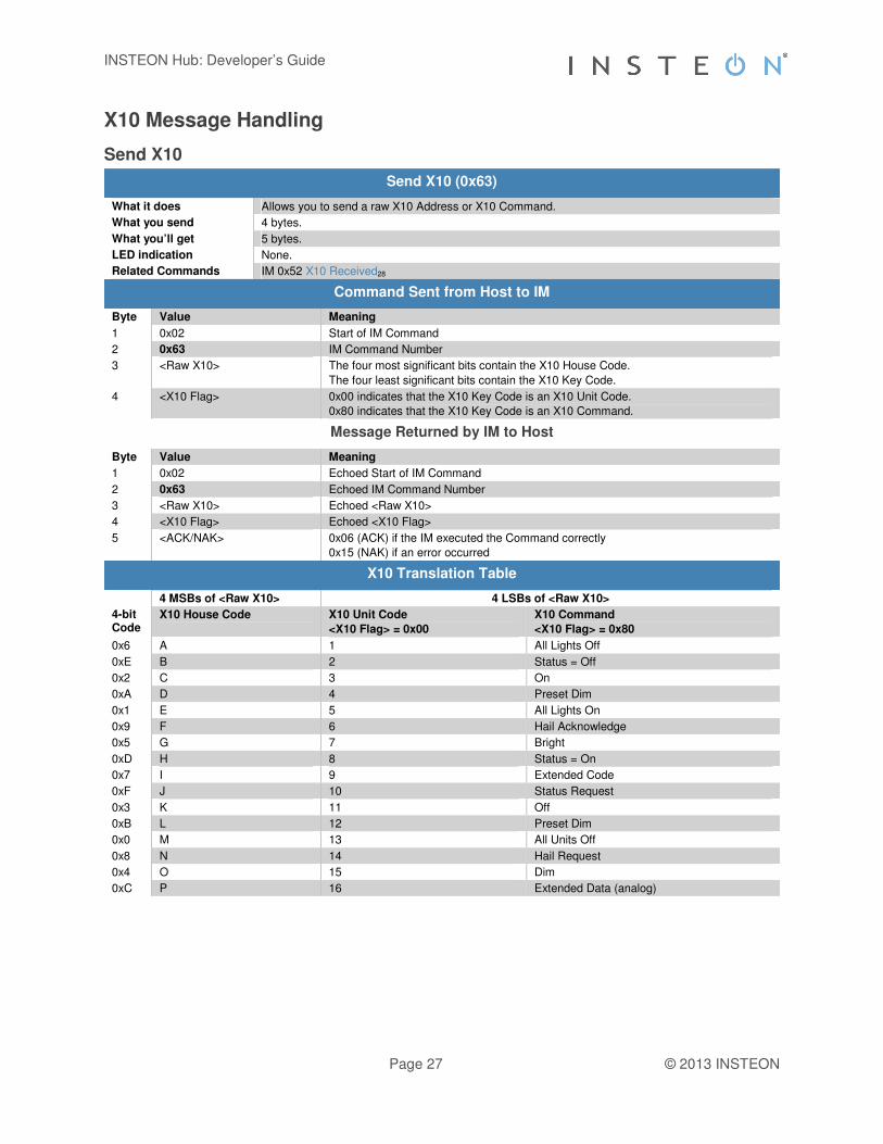
Send X10
Send X10 (0x63)
What it does Allows you to send a raw X10 Address or X10 Command.
What you send 4 bytes.
What you’ll get 5 bytes.
LED indication None.
Related Commands IM 0x52 X10 Received28
Command Sent from Host to IM
Byte Value Meaning
1 0x02 Start of IM Command
2 0x63 IM Command Number
3 <Raw X10> The four most significant bits contain the X10 House Code.
The four least significant bits contain the X10 Key Code.
4 <X10 Flag> 0x00 indicates that the X10 Key Code is an X10 Unit Code.
0x80 indicates that the X10 Key Code is an X10 Command.
Message Returned by IM to Host
Byte Value Meaning
1 0x02 Echoed Start of IM Command
2 0x63 Echoed IM Command Number
3 <Raw X10> Echoed <Raw X10>
4 <X10 Flag> Echoed <X10 Flag>
5 <ACK/NAK> 0x06 (ACK) if the IM executed the Command correctly
0x15 (NAK) if an error occurred
X10 Translation Table
4 MSBs of <Raw X10> 4 LSBs of <Raw X10>
4-bit Code
X10 House Code X10 Unit Code
<X10 Flag> = 0x00
X10 Command
<X10 Flag> = 0x80
0x6 A 1 All Lights Off
0xE B 2 Status = Off
0x2 C 3 On
0xA D 4 Preset Dim
0x1 E 5 All Lights On
0x9 F 6 Hail Acknowledge
0x5 G 7 Bright
0xD H 8 Status = On
0x7 I 9 Extended Code
0xF J 10 Status Request
0x3 K 11 Off
0xB L 12 Preset Dim
0x0 M 13 All Units Off
0x8 N 14 Hail Request
0x4 O 15 Dim
0xC P 16 Extended Data (analog)

INSTEON Hub: Developer’s Guide
Page 28 © 2013 INSTEON
X10 Received
X10 Received (0x52)
What it does Informs you of an X10 byte detected on the powerline.
When you’ll get this Any X10 traffic is detected on the powerline.
What you’ll get 4 bytes.
LED indication The LED will blink during X10 reception.
Related Commands IM 0x63 Send X1027
IM 0x50 INSTEON Standard Message Received22
IM 0x51 INSTEON Extended Message Received23
Message Sent from IM to Host
Byte Value Meaning
1 0x02 Start of IM Command
2 0x52 IM Command Number
3 <Raw X10> The four most significant bits contain the X10 House Code.
The four least significant bits contain the X10 Key Code.
4 <X10 Flag> 0x00 indicates that the X10 Key Code is an X10 Unit Code.
0x80 indicates that the X10 Key Code is an X10 Command.
X10 Translation Table
4 MSBs of <Raw X10> 4 LSBs of <Raw X10>
4-bit Code
X10 House Code X10 Unit Code
<X10 Flag> = 0x00
X10 Command
<X10 Flag> = 0x80
0x6 A 1 All Lights Off
0xE B 2 Status = Off
0x2 C 3 On
0xA D 4 Preset Dim
0x1 E 5 All Lights On
0x9 F 6 Hail Acknowledge
0x5 G 7 Bright
0xD H 8 Status = On
0x7 I 9 Extended Code
0xF J 10 Status Request
0x3 K 11 Off
0xB L 12 Preset Dim
0x0 M 13 All Units Off
0x8 N 14 Hail Request
0x4 O 15 Dim
0xC P 16 Extended Data (analog)

INSTEON Hub: Developer’s Guide
Page 29 © 2013 INSTEON
INSTEON ALL-Link Commands
Send ALL-Link Command
Send ALL-Link Command (0x61)
What it does Sends an ALL-Link Command to an ALL-Link Group of one or more Responders that the IM is ALL-Linked to.
What you send 5 bytes.
What you’ll get 6 bytes for the echo of the Command and then an additional 11 bytes in an INSTEON Standard Message Received22 message for each device in the group that acknowledges ALL-Link Cleanup, or 7 bytes in an ALL-Link Cleanup Failure Report31 message for each device in the group that does not acknowledge ALL-Link Cleanup.
LED indication None.
Related Commands IM 0x50 INSTEON Standard Message Received22
IM 0x56 ALL-Link Cleanup Failure Report31
IM 0x58 ALL-Link Cleanup Status Report32
Command Sent from Host to IM
Byte Value Meaning
1 0x02 Start of IM Command
2 0x61 IM Command Number
3 <ALL-Link Group> ALL-Link Group Number that the ALL-Link Command is sent to
4 <ALL-Link Command> ALL-Link Command
5 <Broadcast Command 2> Sent in the Command 2 field of the ALL-Link Broadcast message only. Command 2 will always contain the ALL-Link Group Number for the ALL-Link Cleanup messages that follow.
Message Returned by IM to Host
Byte Value Meaning
1 0x02 Echoed Start of IM Command
2 0x61 Echoed IM Command Number
3 <ALL-Link Group> Echoed <ALL-Link Group>
4 <ALL-Link Command> Echoed <ALL-Link Command>
5 <Broadcast Command 2> Echoed <Broadcast Command 2>
6 <ACK/NAK> 0x06 (ACK) if the IM executed the Command correctly
0x15 (NAK) if an error occurred or the group does not exist
Notes
The IM automatically sends ALL-Link Cleanup messages to each member of an ALL-Link Group following an ALL-Link Broadcast message. If the IM detects other INSTEON traffic during this process, it will abort the ALL-Link Cleanup sequence and send you an ALL-Link Cleanup Status Report32 with a Status Byte of 0x15 (NAK). The Cleanup sequence proceeds in the order in which the devices in the ALL-Link Group were added to the ALL-Link Database. If the IM finishes sending all of the Cleanup messages, it will send you an ALL-Link Cleanup Status Report32 with a Status Byte of 0x06 (ACK).
For each ALL-Link Cleanup message that the IM sends, you will either receive an INSTEON Standard Message Received22 when the Responder answers with a Cleanup acknowledgement message, or else you will receive an ALL-Link Cleanup Failure Report31 if the Responder fails to answer with a Cleanup acknowledgement message. The IM will send you an ALL-Link Cleanup Status Report32 whether or not every ALL-Link Group member acknowledges the Cleanup Command that the IM sends to it.
You can cause the IM to cancel its own Cleanup sequence by sending it a new Send ALL-Link Command29 or Send INSTEON Standard or Extended Message19 during the time that it is sending a Cleanup sequence (i.e. after it has finished sending an ALL-Link Broadcast message). The IM will send you an ALL-Link Cleanup Status Report32 in those cases.

INSTEON Hub: Developer’s Guide
Page 30 © 2013 INSTEON
The IM first sends an ALL-Link Broadcast message with Max Hops set to 3. When it sends the ensuing ALL-Link Cleanup messages, it sets Max Hops to 1. If the IM’s INSTEON Engine needs to retry a Cleanup message, it will automatically increment Max Hops for each retry, up to a maximum of value of 3.
The IM sends the ALL-Link Broadcast message immediately if there is no other INSTEON traffic. If there is other INSTEON traffic, the IM will wait for one silent powerline zero crossing following a completed INSTEON message. The IM will send the first ALL-Link Cleanup message after a delay of 7 zero crossings. Subsequent Cleanups will go out with a delay of 2 zero crossings.
Do not use this command to control light levels with the Light Start Manual Change INSTEON Command SA 0x17. Use Send INSTEON Standard-length Message19 to send INSTEON Command SD 0x17 instead.
For more information on INSTEON Commands and the latest Command set, please download the current INSTEON Command Tables Document2 from http://code.insteon.com.

INSTEON Hub: Developer’s Guide
Page 31 © 2013 INSTEON
ALL-Link Cleanup Failure Report
ALL-Link Cleanup Failure Report (0x56)
What it does Reports that an ALL-Link Group member did not acknowledge an ALL-Link Cleanup Command.
When you’ll get this An ALL-Link Group member that you are trying to control did not acknowledge the ALL-Link Cleanup Command sent by the IM.
What you’ll get 7 bytes.
LED indication None.
Related Commands IM 0x58 ALL-Link Cleanup Status Report32
Message Sent from IM to Host
Byte Value Meaning
1 0x02 Start of IM Command
2 0x56 IM Command Number
3 0x01 Indicates that this ALL-Link Group member did not acknowledge an ALL-Link Cleanup Command.
4 <ALL-Link Group> Indicates the ALL-Link Group Number that was sent in the ALL-Link Cleanup Command.
5 <ID high byte> The high byte of the INSTEON ID of the device that did not respond.
6 <ID middle byte> The middle byte of the INSTEON ID of the device that did not respond.
7 <ID low byte> The low byte of the INSTEON ID of the device that did not respond.
Notes
The IM automatically sends ALL-Link Cleanup messages to each member of an ALL-Link Group following an ALL-Link Broadcast message. If the IM detects other INSTEON traffic during this process, it will abort the ALL-Link Cleanup sequence. If the Cleanup sequence is aborted, you will not receive this message nor will you receive a Cleanup acknowldgement message for any subsequent devices in the ALL-Link Group. The Cleanup sequence proceeds in the order in which the devices in the ALL-Link Group were added to the ALL-Link Database.
For each ALL-Link Cleanup message the IM sends, you will either receive an INSTEON Standard Message Received22 when the Responder sends you an ACK, or you will receive this message. However, it can take awhile before you receive this message. Worst case, if the IM has to wait for a clear line and then retries the Cleanup message for the maximum of five times, the wait will be 2.150 seconds after sending the ALL-Link Broadcast message, or 1.550 seconds after receiving the first Cleanup acknowledgement or this message. If the Cleanup sequence was aborted due to other INSTEON traffic, you will not get this message even then. However, you will receive ALL-Link Cleanup Status Report32 with a Status Byte of 0x15 (NAK) indicating that the Cleanup sequence was aborted.
It is possible that this ALL-Link Group member did in fact properly receive the ALL-Link Broadcast message that preceded the ALL-Link Cleanup message.

INSTEON Hub: Developer’s Guide
Page 32 © 2013 INSTEON
ALL-Link Cleanup Status Report
ALL-Link Cleanup Status Report (0x58)
What it does Notifies you if a Send ALL-Link Command29 completed with all Cleanup messages sent, or else if Cleanups were interrupted due to other INSTEON traffic.
When you’ll get this After you issue a Send ALL-Link Command29 and the IM finishes sending Cleanups to all members of the ALL-Link Group, or else when the Cleanup sequence is aborted due to other INSTEON traffic.
What you’ll get 3 bytes.
LED indication None.
Related Commands IM 0x61 Send ALL-Link Command29
IM 0x56 ALL-Link Cleanup Failure Report31
Message Sent from IM to Host
Byte Value Meaning
1 0x02 Start of IM Command
2 0x58 IM Command Number
3 <Status Byte> <0x06> (ASCII ACK) The ALL-Link Command sequence initiated previously using Send ALL-Link Command29 completed. The IM first sent an ALL-Link Broadcast message, followed by ALL-Link Cleanup messages sent to all members of the specified ALL-Link Group. If any member of the ALL-Link Group does not return a Cleanup acknowledgement, you will receive an ALL-Link Cleanup Failure Report31 from that member.
<0x15> (ASCII NAK) The ALL-Link Command sequence initiated previously using Send ALL-Link Command29 terminated before the IM sent ALL-Link Cleanup messages to all members of the specified ALL-Link Group. This is normal behavior when the IM detects INSTEON traffic from other devices.
Notes
The IM automatically sends ALL-Link Cleanup messages to each member of an ALL-Link Group following an ALL-Link Broadcast message. If the IM detects other INSTEON traffic during this process, it will abort the ALL-Link Cleanup sequence and send you this message with a Status Byte of 0x15 (NAK). The Cleanup sequence proceeds in the order in which the devices in the ALL-Link Group were added to the ALL-Link Database. If the IM finishes sending all of the Cleanup messages, it will send you this message with a Status Byte of 0x06 (ACK).
For each ALL-Link Cleanup message that the IM sends, you will either receive an INSTEON Standard Message Received22 when the Responder answers with a Cleanup acknowledgement message, or else you will receive an ALL-Link Cleanup Failure Report31 if the Responder fails to answer with a Cleanup acknowledgement message. The IM will send you this message whether or not every ALL-Link Group member acknowledges the Cleanup Command that the IM sends to it.
You can cause the IM to cancel its own Cleanup sequence by sending it a new Send ALL-Link Command29 or Send INSTEON Standard or Extended Message19 during the time that it is sending a Cleanup sequence (i.e. after it has finished sending an ALL-Link Broadcast message). The IM will send you this message in those cases.

INSTEON Hub: Developer’s Guide
Page 33 © 2013 INSTEON
ALL-Linking Session Management
Start ALL-Linking
Start ALL-Linking (0x64)
What it does Puts the IM into ALL-Linking mode without using the SET Button.
What you send 4 bytes.
What you’ll get 5 bytes for this Command response and then an additional 10 bytes in an ALL-Linking Completed35 message once a successful ALL-Link has been established.
LED indication The LED will blink continuously at a rate of ½ second on and ½ second off until the ALL-Link is completed or canceled.
Related Commands IM 0x53 ALL-Linking Completed35
IM 0x65 Cancel ALL-Linking34
Command Sent from Host to IM
Byte Value Meaning
1 0x02 Start of IM Command
2 0x64 IM Command Number
3 <Link Code> The type of ALL-Link to establish.
0x00 ALL-Links the IM as a Responder (slave).
0x01 ALL-Links the IM as a Controller (master).
0x03 ALL-Links the IM as a Controller when the IM initiates ALL-Linking, or as a Responder when another device initiates ALL-Linking.
0xFF Deletes the ALL-Link.
4 <ALL-Link Group> The ALL-Link Group Number to be linked to or deleted.
Message Returned by IM to Host
Byte Value Meaning
1 0x02 Echoed Start of IM Command
2 0x64 Echoed IM Command Number
3 <Code> Echoed <Code>
4 <ALL-Link Group> Echoed <ALL-Link Group>
5 <ACK/NAK> 0x06 (ACK) if the IM executed the Command correctly 0x15 (NAK) if an error occurred

INSTEON Hub: Developer’s Guide
Page 34 © 2013 INSTEON
Cancel ALL-Linking
Cancel ALL-Linking (0x65)
What it does Cancels the ALL-Linking process that was started either by holding down the IM’s SET Button or by sending a Start ALL-Linking33 Command to the IM.
What you send 2 bytes.
What you’ll get 3 bytes.
LED indication The LED will stop blinking.
Related Commands IM 0x64 Start ALL-Linking33
IM 0x54 Button Event Report51
Command Sent from Host to IM
Byte Value Meaning
1 0x02 Start of IM Command
2 0x65 IM Command Number
Message Returned by IM to Host
Byte Value Meaning
1 0x02 Echoed Start of IM Command
2 0x65 Echoed IM Command Number
3 <ACK/NAK> 0x06 (ACK) if the IM executed the Command correctly 0x15 (NAK) if an error occurred

INSTEON Hub: Developer’s Guide
Page 35 © 2013 INSTEON
ALL-Linking Completed
ALL-Linking Completed (0x53)
What it does Informs you of a successful ALL-Linking procedure.
When you’ll get this An ALL-Linking procedure has been completed between the IM and either a Controller or Responder.
What you’ll get 10 bytes.
LED indication None.
Related Commands IM 0x64 Start ALL-Linking33
IM 0x65 Cancel ALL-Linking34
Message Sent from IM to Host
Byte Value Meaning
1 0x02 Start of IM Command
2 0x53 IM Command Number
3 <Link Code> Indicates the type of link made.
0x00 means the IM is a Responder (slave) to this device
0x01 means the IM is a Controller (master) of this device
0xFF means the ALL-Link to the device was deleted
If done manually (by pushing the SET Button) the Controller / Responder relationship between the IM and the device is determined automatically. You can assign the Controller / Responder relationship unconditionally by using the Start ALL-Linking33 Command.
4 <ALL-Link Group> Indicates the ALL-Link Group Number that was assigned to this link.
If done manually (by pushing the SET Button) the ALL-Link Group Number is automatically assigned by the IM. You can assign ALL-Link Group Numbers unconditionally by using the Start ALL-Linking33 Command.
5 <ID high byte> The high byte of the INSTEON ID of the device that was ALL-Linked.
6 <ID middle byte> The middle byte of the INSTEON ID of the device that was ALL-Linked.
7 <ID low byte> The low byte of the INSTEON ID of the device that was ALL-Linked.
8 <Device Category> The Device Category (DevCat) of the Responder device that was ALL-Linked.
(Only valid when the IM is a Controller)
9 <Device Subcategory> The Device Subcategory (SubCat) of the Responder device that was ALL-Linked.
(Only valid when the IM is a Controller)
10 <0xFF | Firmware Version> 0xFF for newer devices.
For legacy devices this is the firmware version of the Responder device that was ALL-Linked.
(Only valid when the IM is a Controller)
INSTEON Hub: Developer’s Guide
Page 36 © 2013 INSTEON
ALL-Link Database Management
Get First ALL-Link Record
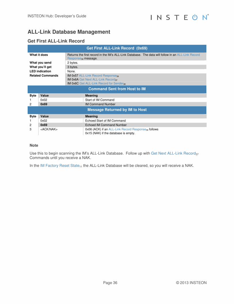
Get First ALL-Link Record (0x69)
What it does Returns the first record in the IM’s ALL-Link Database. The data will follow in an ALL-Link Record Response39 message.
What you send 2 bytes.
What you’ll get 3 bytes.
LED indication None.
Related Commands IM 0x57 ALL-Link Record Response39
IM 0x6A Get Next ALL-Link Record37
IM 0x6C Get ALL-Link Record for Sender38
Command Sent from Host to IM
Byte Value Meaning
1 0x02 Start of IM Command
2 0x69 IM Command Number
Message Returned by IM to Host
Byte Value Meaning
1 0x02 Echoed Start of IM Command
2 0x69 Echoed IM Command Number
3 <ACK/NAK> 0x06 (ACK) if an ALL-Link Record Response39 follows
0x15 (NAK) if the database is empty.
Note
Use this to begin scanning the IM’s ALL-Link Database. Follow up with Get Next ALL-Link Record37 Commands until you receive a NAK.
In the IM Factory Reset State11 the ALL-Link Database will be cleared, so you will receive a NAK.

INSTEON Hub: Developer’s Guide
Page 37 © 2013 INSTEON
Get Next ALL-Link Record
Get Next ALL-Link Record (0x6A)
What it does Returns the next record in the IM’s ALL-Link Database. The data will follow in an ALL-Link Record Response39 message.
What you send 2 bytes.
What you’ll get 3 bytes.
LED indication None.
Related Commands IM 0x57 ALL-Link Record Response39
IM 0x69 Get First ALL-Link Record36
IM 0x6C Get ALL-Link Record for Sender38
Command Sent from Host to IM
Byte Value Meaning
1 0x02 Start of IM Command
2 0x6A IM Command Number
Message Returned by IM to Host
Byte Value Meaning
1 0x02 Echoed Start of IM Command
2 0x6A Echoed IM Command Number
3 <ACK/NAK> 0x06 (ACK) if an ALL-Link Record Response39 follows
0x15 (NAK) if there are no more records.
Note
Use this to continue scanning the IM’s ALL-Link Database until you receive a NAK. Begin the scan up with a Get First ALL-Link Record36 Command.
In the IM Factory Reset State11 the ALL-Link Database will be cleared, so you will receive a NAK.

INSTEON Hub: Developer’s Guide
Page 38 © 2013 INSTEON
Get ALL-Link Record for Sender
Get ALL-Link Record for Sender (0x6C)
What it does This gets the record from the IM’s ALL-Link Database for the last INSTEON message received from an INSTEON device that is in the IM’s ALL-Link Database. The data will follow in an ALL-Link Record Response39 message.
What you send 2 bytes.
What you’ll get 3 bytes.
LED indication None.
Related Commands IM 0x57 ALL-Link Record Response39
IM 0x69 Get First ALL-Link Record36
IM 0x6A Get Next ALL-Link Record37
Command Sent from Host to IM
Byte Value Meaning
1 0x02 Start of IM Command
2 0x6C IM Command Number
Message Returned by IM to Host
Byte Value Meaning
1 0x02 Echoed Start of IM Command
2 0x6C Echoed IM Command Number
3 <ACK/NAK> 0x06 (ACK) if an ALL-Link Record Response39 follows
0x15 (NAK) if the last INSTEON message received had a From Address not in the IM’s ALL-Link Database.
Note
If you send this after receiving an INSTEON message from an INSTEON device that is not in the IM’s ALL-Link Database, you will receive a NAK in response.
Sending a Get Next ALL-Link Record37 Command after this will return the ALL-Link Record that follows this one, but your actual position within the ALL-Link Database will be unknown (unless you are at the end).
In the IM Factory Reset State11 the ALL-Link Database will be cleared, so you will receive a NAK.
INSTEON Hub: Developer’s Guide
Page 39 © 2013 INSTEON
ALL-Link Record Response
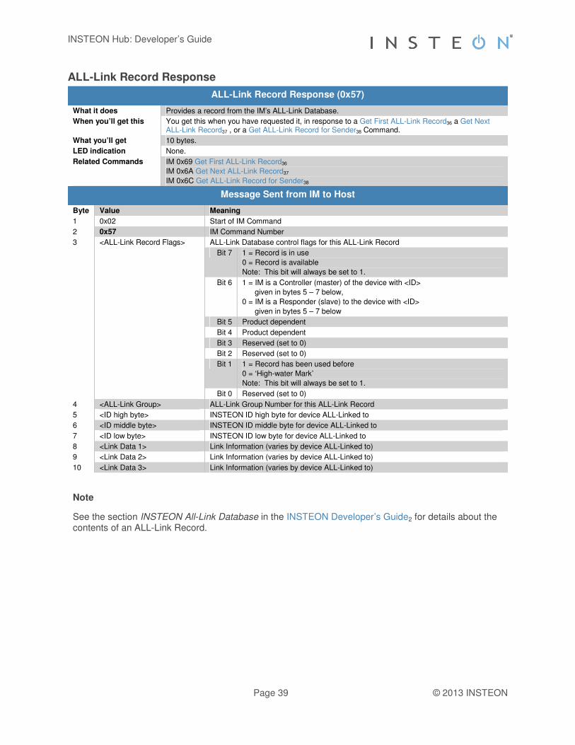
ALL-Link Record Response (0x57)
What it does Provides a record from the IM’s ALL-Link Database.
When you’ll get this You get this when you have requested it, in response to a Get First ALL-Link Record36 a Get Next ALL-Link Record37 , or a Get ALL-Link Record for Sender38 Command.
What you’ll get 10 bytes.
LED indication None.
Related Commands IM 0x69 Get First ALL-Link Record36
IM 0x6A Get Next ALL-Link Record37
IM 0x6C Get ALL-Link Record for Sender38
Message Sent from IM to Host
Byte Value Meaning
1 0x02 Start of IM Command
2 0x57 IM Command Number
3 <ALL-Link Record Flags> ALL-Link Database control flags for this ALL-Link Record
Bit 7 1 = Record is in use
0 = Record is available
Note: This bit will always be set to 1.
Bit 6 1 = IM is a Controller (master) of the device with <ID>
given in bytes 5 – 7 below,
0 = IM is a Responder (slave) to the device with <ID>
given in bytes 5 – 7 below
Bit 5 Product dependent
Bit 4 Product dependent
Bit 3 Reserved (set to 0)
Bit 2 Reserved (set to 0)
Bit 1 1 = Record has been used before
0 = ‘High-water Mark’
Note: This bit will always be set to 1.
Bit 0 Reserved (set to 0)
4 <ALL-Link Group> ALL-Link Group Number for this ALL-Link Record
5 <ID high byte> INSTEON ID high byte for device ALL-Linked to
6 <ID middle byte> INSTEON ID middle byte for device ALL-Linked to
7 <ID low byte> INSTEON ID low byte for device ALL-Linked to
8 <Link Data 1> Link Information (varies by device ALL-Linked to)
9 <Link Data 2> Link Information (varies by device ALL-Linked to)
10 <Link Data 3> Link Information (varies by device ALL-Linked to)
Note
See the section INSTEON All-Link Database in the INSTEON Developer’s Guide2 for details about the contents of an ALL-Link Record.

INSTEON Hub: Developer’s Guide
Page 40 © 2013 INSTEON
Manage ALL-Link Record
Manage ALL-Link Record (0x6F)
What it does Updates the IM’s ALL-Link Database (ALDB) with the ALL-Link Record information you send. Use caution with this Command—the IM does not check the validity of the data.
What you send 11 bytes.
What you’ll get 12 bytes.
LED indication None.
Related Commands IM 0x57 ALL-Link Record Response39
Command Sent from Host to IM
Byte Value Meaning
1 0x02 Start of IM Command
2 0x6F IM Command Number
3 <Control Code> What to do with the ALL-Link Record
0x00 Find First
Starting at the top of the ALDB, search for the first ALL-Link Record matching the <ALL-Link Group> and <ID> in bytes 5 – 8. The search ignores byte 4, <ALL-Link Record Flags>.
You will receive an ACK at the end of the returned message if such an ALL-Link Record exists, or else a NAK if it doesn’t. If the record exists, the IM will return it in an ALL-Link Record Response39 message.
0x01 Find Next
Search for the next ALL-Link Record following the one found using <Control Code> 0x00 above. This allows you to find both Controller and Responder records for a given <ALL-Link Group> and <ID>. Be sure to use the same <ALL-Link Group> and <ID> (bytes 5 – 8) as you used for <Control Code> 0x00.
You will receive an ACK at the end of the returned message if another matching ALL-Link Record exists, or else a NAK if it doesn’t. If the record exists, the IM will return it in an ALL-Link Record Response39 message.
0x20 Modify First Found or Add
Modify an existing or else add a new ALL-Link Record for either a Controller or Responder.
Starting at the top of the ALDB, search for the first ALL-Link Record matching the <ALL-Link Group> and <ID> in bytes 5 – 8. The search ignores byte 4, <ALL-Link Record Flags>.
If such an ALL-Link Record exists, overwrite it with the data in bytes 4 – 11; otherwise, create a new ALL-Link Record using bytes 4 – 11.
Note that the IM will copy <ALL-Link Record Flags> you supplied in byte 4 below directly into the <ALL-Link Record Flags> byte of the ALL-Link Record in an ALDB-L (linear) database. Use caution, because you can damage an ALDB-L if you misuse this Command. For instance, if you zero the <ALL-Link Record Flags> byte in the first ALL-Link Record, the IM’s ALDB-L database will then appear empty.
0x40 Modify First Controller Found or Add
Modify an existing or else add a new Controller (master) ALL-Link Record.
Starting at the top of the ALDB, search for the first ALL-Link Controller Record matching the <ALL-Link Group> and <ID> in bytes 5 – 8. An ALL-Link Controller Record has bit 6 of its <ALL-Link Record Flags> byte set to 1.
If such a Controller ALL-Link Record exists, overwrite it with the data in bytes 5 – 11; otherwise, create a new ALL-Link Record using bytes 5 – 11. In either case, the IM will set bit 6 of the <ALL-Link Record Flags> byte in the ALL-Link Record to 1 to indicate that the record is for a Controller.
0x41 Modify First Responder Found or Add
Modify an existing or else add a new Responder (slave) ALL-Link Record.
Starting at the top of the ALDB, search for the first ALL-Link Responder Record matching the <ALL-Link Group> and <ID> in bytes 5 – 8. An ALL-Link Responder Record has bit 6 of its <ALL-Link Record Flags> byte cleared to 0.
If such a Responder ALL-Link Record exists, overwrite it with the data in bytes 5 – 11; otherwise, create a new ALL-Link Record using bytes 5 – 11. In either case, The IM will clear bit 6 of the <ALL-Link Record Flags> byte in the ALL-Link Record to 0 to indicate that the record is for a Responder.
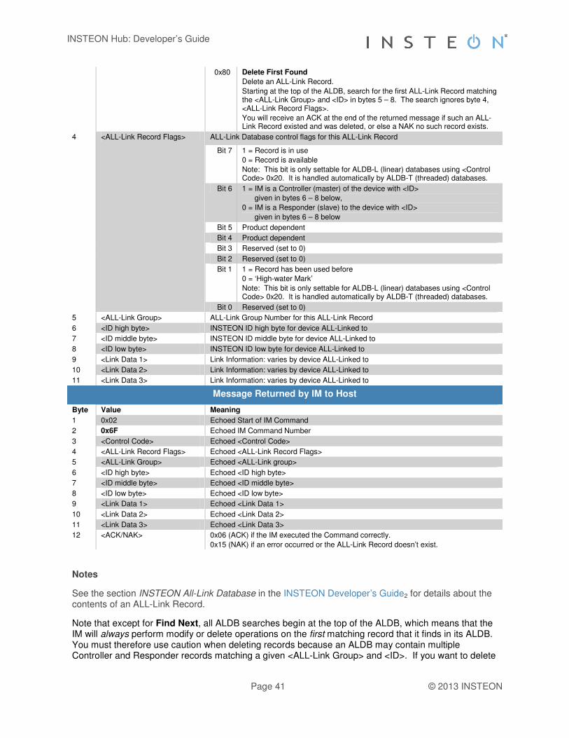
INSTEON Hub: Developer’s Guide
Page 41 © 2013 INSTEON
0x80 Delete First Found
Delete an ALL-Link Record.
Starting at the top of the ALDB, search for the first ALL-Link Record matching the <ALL-Link Group> and <ID> in bytes 5 – 8. The search ignores byte 4, <ALL-Link Record Flags>.
You will receive an ACK at the end of the returned message if such an ALL-Link Record existed and was deleted, or else a NAK no such record exists.
4 <ALL-Link Record Flags> ALL-Link Database control flags for this ALL-Link Record
Bit 7 1 = Record is in use
0 = Record is available
Note: This bit is only settable for ALDB-L (linear) databases using <Control Code> 0x20. It is handled automatically by ALDB-T (threaded) databases.
Bit 6 1 = IM is a Controller (master) of the device with <ID>
given in bytes 6 – 8 below,
0 = IM is a Responder (slave) to the device with <ID>
given in bytes 6 – 8 below
Bit 5 Product dependent
Bit 4 Product dependent
Bit 3 Reserved (set to 0)
Bit 2 Reserved (set to 0)
Bit 1 1 = Record has been used before
0 = ‘High-water Mark’
Note: This bit is only settable for ALDB-L (linear) databases using <Control Code> 0x20. It is handled automatically by ALDB-T (threaded) databases.
Bit 0 Reserved (set to 0)
5 <ALL-Link Group> ALL-Link Group Number for this ALL-Link Record
6 <ID high byte> INSTEON ID high byte for device ALL-Linked to
7 <ID middle byte> INSTEON ID middle byte for device ALL-Linked to
8 <ID low byte> INSTEON ID low byte for device ALL-Linked to
9 <Link Data 1> Link Information: varies by device ALL-Linked to
10 <Link Data 2> Link Information: varies by device ALL-Linked to
11 <Link Data 3> Link Information: varies by device ALL-Linked to
Message Returned by IM to Host
Byte Value Meaning
1 0x02 Echoed Start of IM Command
2 0x6F Echoed IM Command Number
3 <Control Code> Echoed <Control Code>
4 <ALL-Link Record Flags> Echoed <ALL-Link Record Flags>
5 <ALL-Link Group> Echoed <ALL-Link group>
6 <ID high byte> Echoed <ID high byte>
7 <ID middle byte> Echoed <ID middle byte>
8 <ID low byte> Echoed <ID low byte>
9 <Link Data 1> Echoed <Link Data 1>
10 <Link Data 2> Echoed <Link Data 2>
11 <Link Data 3> Echoed <Link Data 3>
12 <ACK/NAK> 0x06 (ACK) if the IM executed the Command correctly.
0x15 (NAK) if an error occurred or the ALL-Link Record doesn’t exist.
Notes
See the section INSTEON All-Link Database in the INSTEON Developer’s Guide2 for details about the contents of an ALL-Link Record.
Note that except for Find Next, all ALDB searches begin at the top of the ALDB, which means that the IM will always perform modify or delete operations on the first matching record that it finds in its ALDB. You must therefore use caution when deleting records because an ALDB may contain multiple Controller and Responder records matching a given <ALL-Link Group> and <ID>. If you want to delete

INSTEON Hub: Developer’s Guide
Page 42 © 2013 INSTEON
only one of the matching records, then you should:
1. Use Find First and Find Next to find and buffer all of the records matching the <ALL-Link Group> and <ID>,
2. Use Delete First Found enough times to delete all of the matching records,
3. Put back the records you did not want to delete using Modify First Controller Found or Add or Modify First Responder Found or Add.
Please be aware that you can damage an ALDB-L (linear) database if you misuse the Modify First Found or Add operation, <Control Code> 0x20. For instance, if you zero bit 1 of the <ALL-Link Record Flags> byte in the first record in an ALDB-L, the ALDB-L will then appear empty. Or, if you zero bit 7 of the <ALL-Link Record Flags> byte in an ALDB-L record, then that record will appear deleted. In an ALDB-T (threaded) database, the IM handles those bits for you automatically, so the Modify First Found or Add operation is not so risky. Nevertheless, it is always preferable to use Modify First Controller Found or Add or Modify First Responder Found or Add instead, because with Modify First Found or Add you cannot be sure if you are modifying a record for a Controller or Responder.

INSTEON Hub: Developer’s Guide
Page 43 © 2013 INSTEON
IM Status Management
Reset the IM
Reset the IM (0x67)
What it does Puts the IM into the IM Factory Reset State11, which clears the entire ALL-Link Database.
What you send 2 bytes.
What you’ll get 3 bytes.
LED indication While the reset procedure is being processed, the Status LED will turn off. At the conclusion of the reset procedure, the Status LED will illuminate steadily.
Related Commands IM 0x55 User Reset Detected44
Command Sent from Host to IM
Byte Value Meaning
1 0x02 Start of IM Command
2 0x67 IM Command Number
Message Returned by IM to Host
Byte Value Meaning
1 0x02 Echoed Start of IM Command
2 0x67 Echoed IM Command Number
3 <ACK/NAK> 0x06 (ACK) if the IM executed the Command correctly 0x15 (NAK) if an error occurred
Notes
The IM will send the <ACK/NAK> byte after it erases the EEPROM.
~20 seconds for models with external EEPROM (for product revisions less than 2.4 or firmware verisons 52 or earlier.
~2 seconds for models with no external EEPROM
Effective with product revisions 2.5 or greater, the reset time is reduced to ~3 seconds.
See the IM Factory Reset State11 section for complete information on the state of the IM after sending this Command.

INSTEON Hub: Developer’s Guide
Page 44 © 2013 INSTEON
User Reset Detected
User Reset Detected (0x55)
What it does Reports that the user manually put the IM into the IM Factory Reset State11.
When you’ll get this The user held down the IM’s SET Button for at least 10 seconds when power was first applied.
What you’ll get 2 bytes (not until about 20 seconds after applying power to the IM with the SET Button held down).
LED indication The LED will turn off for about 20 seconds. Once the LED turns back on the reset is complete.
Related Commands IM 0x67 Reset the IM43
Message Sent from IM to Host
Byte Value Meaning
1 0x02 Start of IM Command
2 0x55 IM Command Number
Notes
The IM will send this message after it erases the EEPROM.
~20 seconds for models with external EEPROM (for product revisions less than 2.4 or firmware verisons 52 or earlier.
~2 seconds for models with no external EEPROM
Effective with product revisions 2.5 or greater, the reset time is reduced to ~3 seconds.
See the IM Factory Reset State11 section for complete information on the state of the IM after receiving this message.

INSTEON Hub: Developer’s Guide
Page 45 © 2013 INSTEON
Get IM Configuration
Get IM Configuration (0x73)
What it does Returns the IM’s Configuration Flags byte. Also returns two spare bytes of data reserved for future use.
What you send 2 bytes.
What you’ll get 6 bytes.
LED indication None.
Related Commands IM 0x6B Set IM Configuration46
Command Sent from Host to IM
Byte Value Meaning
1 0x02 Start of IM Command
2 0x73 IM Command Number
Message Returned by IM to Host
Byte Value Meaning
1 0x02 Echoed Start of IM Command
2 0x73 Echoed IM Command Number
3 <IM Configuration Flags> IM’s Configuration Flags. See Set IM Configuration46 for bit definitions.
4 <Spare 1> 0x00, reserved for future use
5 <Spare 2> 0x00, reserved for future use
6 <ACK/NAK> 0x06 (ACK) if the IM executed the Command correctly
0x15 (NAK) if an error occurred
Note
Because Set IM Configuration46 sets all of the <IM Configuration Flags> at once, to change an individual bit, first use this Command to determine the current state of all of the <IM Configuration Flags>.

INSTEON Hub: Developer’s Guide
Page 46 © 2013 INSTEON
Set IM Configuration
Set IM Configuration (0x6B)
What it does Allows you change operating parameters of the IM.
What you send 3 bytes.
What you’ll get 4 bytes.
LED indication None.
Related Commands IM 0x73 Get IM Configuration45
IM 0x54 Button Event Report51
IM 0x50 INSTEON Standard Message Received22
IM 0x51 INSTEON Extended Message Received23
IM 0x6D LED On52
IM 0x6E LED Off53
Command Sent from Host to IM
Byte Value Meaning
1 0x02 Start of IM Command
2 0x6B IM Command Number
3 <IM Configuration Flags> Flag byte containing Configuration Flags that affect IM operation. These all default to 0.
Bit 7 = 1 Disables automatic linking when the user pushes and holds the SET Button (see Button Event Report51).
Bit 6 = 1 Puts the IM into Monitor Mode (see About Monitor Mode46 in the Notes below).
Bit 5 = 1 Disables automatic LED operation by the IM. The host must now control the IM’s LED using LED On52 and LED Off53.
Bit 4 = 1 Disable host communications Deadman feature (i.e. allow host to delay more than 240 milliseconds between sending bytes to the IM).
Bit 3 = 1 Serial commands to the interface will NAK if it is busy processing an INSTEON command.
Bits 2 - 0 Reserved for internal use. Set these bits to 0.
Message Returned by IM to Host
Byte Value Meaning
1 0x02 Echoed Start of IM Command
2 0x6B Echoed IM Command Number
3 <IM Configuration Flags> Echoed <IM Configuration Flags>
4 <ACK/NAK> 0x06 (ACK) if the IM executed the Command correctly.
0x15 (NAK) if an error occurred.
Notes
When the IM is in the IM Factory Reset State11, the <IM Configuration Flags> will all be set to zero.
This Command sets all of the <IM Configuration Flags> at once. To change an individual bit, first use Get IM Configuration45 to determine the current state of all of the <IM Configuration Flags>.
About Monitor Mode
Normally, the IM will only send the host an INSTEON Standard Message Received22 or INSTEON Extended Message Received23 notification when it receives an INSTEON messages directed specifically to the IM. There are three possibilities:
1. The IM received a Direct message with a To Address matching the IM’s INSTEON ID,
2. The IM received an ALL-Link Broadcast message sent to an ALL-Link Group that the IM belongs to as a Responder (i.e. the message’s From Address and ALL-Link Group Number match a Responder entry in the IM’s ALL-Link Database), or
3. The IM received an ALL-Link Cleanup message with a To Address matching the IM’s INSTEON ID and the message’s From Address and ALL-Link Group Number match a

INSTEON Hub: Developer’s Guide
Page 47 © 2013 INSTEON
Responder entry in the IM’s ALL-Link Database.
In Monitor Mode, the IM will also notify the host of received INSTEON messages that contain a From Address matching any INSTEON ID in the IM’s ALL-Link Database, even if the To Address does not match the IM’s INSTEON ID or the IM does not belong to an ALL-Link Group associated with the message. In other words, if the message originator is in the IM’s ALL-Link Database as either a Controller or Responder, the IM will pass the message to the host even if it is not specifically directed to the IM. In this way you can monitor messages between other INSTEON devices as long as the sender is in the IM’s ALL-Link Database.
Please be aware that the IM may not always detect this traffic. If the message originator and addressee are close to one another and the IM is farther away, the message originator may not cause the message to hop enough times for the IM to hear it. To know for sure what an INSTEON device’s status is, you can usually query it directly using an appropriate INSTEON Direct Command. For more information on INSTEON Commands and the latest Command set, please download the current INSTEON Command Tables Document2 from http://code.insteon.com.

INSTEON Hub: Developer’s Guide
Page 48 © 2013 INSTEON
Get IM Info
Get IM Info (0x60)
What it does Identifies the IM’s 3 byte INSTEON ID, Device Category (DevCat), Device Subcategory (SubCat), and firmware version.
What you send 2 bytes.
What you’ll get 9 bytes.
LED indication None.
Related Commands IM 0x66 Set Host Device Category49
IM 0x73 Get IM Configuration45
IM 0x6B Set IM Configuration46
Command Sent from Host to IM
Byte Value Meaning
1 0x02 Start of IM Command
2 0x60 IM Command Number
Message Returned by IM to Host
Byte Value Meaning
1 0x02 Echoed Start of IM Command
2 0x60 Echoed IM Command Number
3 <ID high byte> IM’s INSTEON ID high byte
4 <ID middle byte> IM’s INSTEON ID middle byte
5 <ID low byte> IM’s INSTEON ID low byte
6 <Device Category> IM’s Device Category
7 <Device Subcategory> IM’s Device Subcategory
8 <Firmware Version> IM’s Firmware Version
9 <ACK/NAK> 0x06 (ACK) if the IM executed the Command correctly
0x15 (NAK) if an error occurred
Note
Using the Set Host Device Category49 Command to change the host’s DevCat and SubCat will only affect the data transmitted by the IM to other INSTEON devices during ALL-Linking.
When the host sends this Command to the IM, the IM will return the original DevCat, SubCat and firmware version hard-coded into the IM’s firmware at the factory.

INSTEON Hub: Developer’s Guide
Page 49 © 2013 INSTEON
Set Host Device Category
Set Host Device Category (0x66)
What it does Lets you set the Device Category (DevCat) and Device Subcategory (SubCat) of the host device connected to the IM.
What you send 5 bytes.
What you’ll get 6 bytes.
LED indication None.
Related Commands IM 0x60 Get IM Info48
Command Sent from Host to IM
Byte Value Meaning
1 0x02 Start of IM Command
2 0x66 IM Command Number
3 <Device Category> INSTEON Device Category (DevCat) of the host device connected to the IM.
4 <Device Subcategory> INSTEON Device Subcategory (SubCat) of the host device connected to the IM.
5 <0xFF | Firmware Version> 0xFF
In legacy devices this byte represented a BCD-encoded firmware version. The high nibble (4 bits) gave the major revision number and the low nibble gave the minor revision.
In current devices use the INSTEON Product Data Request and Product Data Response Commands to retrieve the firmware version as user-defined data.
Message Returned by IM to Host
Byte Value Meaning
1 0x02 Echoed Start of IM Command
2 0x66 Echoed IM Command Number
3 <Device Category> Echoed <Device Category>
4 <Device Subcategory> Echoed <Device Subcategory>
5 <0xFF | Firmware Version> Echoed <0xFF> or <Firmware Version>
6 <ACK/NAK> 0x06 (ACK) if the IM executed the Command correctly
0x15 (NAK) if an error occurred
Notes
For INSTEON compliance, you must obtain an approved DevCat and SubCat assignment for your host product from SmartLabs.
The IM stores these values in EEPROM so they will not be erased if power is lost.
When the IM is in the IM Factory Reset State11, these values will be set to those hard-coded into the IM’s firmware at the factory.
Using this Command to change the host’s DevCat and SubCat will only affect the data transmitted by the IM to other INSTEON devices during ALL-Linking.
When the host sends a Get IM Info48 Command to the IM, the IM will return the original DevCat, SubCat and firmware version hard-coded into the IM’s firmware at the factory.
For the latest list of assigned INSTEON DevCats, please download the INSTEON Device Categories and Product Keys Document2 from http://code.insteon.com.

INSTEON Hub: Developer’s Guide
Page 50 © 2013 INSTEON
RF Sleep
RF Sleep (0x72)
What it does Directs an RF IM to go into power saving sleep mode. To wake up the RF IM, send it one byte of serial data.
What you send 2 bytes.
What you’ll get 3 bytes.
LED indication None.
Related Commands None.
Command Sent from Host to IM
Byte Value Meaning
1 0x02 Start of IM Command
2 0x72 IM Command Number
3 <Command 1 Data> Data byte to place into the Command 1 field 2 of the ACK response.
4 <Command 2 Data> Data byte to place into the Command 2 field 2 of the ACK response.
Message Returned by IM to Host
Byte Value Meaning
1 0x02 Echoed Start of IM Command
2 0x72 Echoed IM Command Number
3 <Command 1 Data> Echoed <Command 1 Data>
4 <Command 2 Data> Echoed <Command 2 Data>
5 <ACK/NAK> 0x06 (ACK) if the IM executed the Command correctly.
0x15 (NAK) if an error occurred.
Notes
It does not matter what byte you send serially to wake up the RF IM.
When the RF IM wakes up, it will reinitialize, but memory will not be altered as it would be in the IM Factory Reset State11. Wait a minimum of 40 milliseconds before sending any further IM Serial Commands.

INSTEON Hub: Developer’s Guide
Page 51 © 2013 INSTEON
IM Input/Output
Button Event Report
Button Event Report (0x54)
What it does Reports user SET Button events.
When you’ll get this The user operates the SET Button, or if they exist, Button 2 or Button 3.
What you’ll get 3 bytes.
LED indication If the event is SET Button Press and Hold the IM will automatically go into ALL-Linking mode which will cause the LED to blink continuously at a rate of ½ second on and ½ second off. Automatic linking may be turned off by setting IM Configuration Flags bit 7 (see Set IM Configuration46).
Related Commands IM 0x53 ALL-Linking Completed35
IM 0x64 Start ALL-Linking33
IM 0x65 Cancel ALL-Linking34
Message Sent from IM to Host
Byte Value Meaning
1 0x02 Start of IM Command
2 0x54 IM Command Number
3 <Button Event> Indicates the type of SET Button event that occurred.
0x02 The SET Button was Tapped
0x03 There was a SET Button Press and Hold for more than three seconds.
This automatically puts the IM into ALL-Linking mode unless IM Configuration Flags bit 7 is set.
0x04 The SET Button was released after a SET Button Press and Hold event was recorded.
0x12 Button 2 was Tapped
0x13 There was a Button 2 Press and Hold for more than three seconds.
0x14 Button 2 was released after a Button 2 Press and Hold event was recorded.
0x22 Button 3 was Tapped
0x23 There was a Button 3 Press and Hold for more than three seconds.
0x24 Button 3 was released after a Button 3 Press and Hold event was recorded.
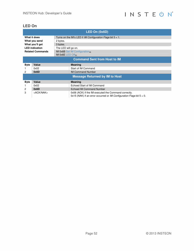
INSTEON Hub: Developer’s Guide
Page 52 © 2013 INSTEON
LED On
LED On (0x6D)
What it does Turns on the IM’s LED if IM Configuration Flags bit 5 = 1.
What you send 2 bytes.
What you’ll get 3 bytes.
LED indication The LED will go on.
Related Commands IM 0x6B Set IM Configuration46
IM 0x6E LED Off53
Command Sent from Host to IM
Byte Value Meaning
1 0x02 Start of IM Command
2 0x6D IM Command Number
Message Returned by IM to Host
Byte Value Meaning
1 0x02 Echoed Start of IM Command
2 0x6D Echoed IM Command Number
3 <ACK/NAK> 0x06 (ACK) if the IM executed the Command correctly.
0x15 (NAK) if an error occurred or IM Configuration Flags bit 5 = 0.

INSTEON Hub: Developer’s Guide
Page 53 © 2013 INSTEON
LED Off
LED Off (0x6E)
What it does Turns off the IM’s LED if IM Configuration Flags bit 5 = 1.
What you send 2 bytes.
What you’ll get 3 bytes.
LED indication The LED will go off.
Related Commands IM 0x6B Set IM Configuration46
IM 0x6D LED On52
Command Sent from Host to IM
Byte Value Meaning
1 0x02 Start of IM Command
2 0x6E IM Command Number
Message Returned by IM to Host
Byte Value Meaning
1 0x02 Echoed Start of IM Command
2 0x6E Echoed IM Command Number
3 <ACK/NAK> 0x06 (ACK) if the IM executed the Command correctly.
0x15 (NAK) if an error occurred or IM Configuration Flags bit 5 = 0.
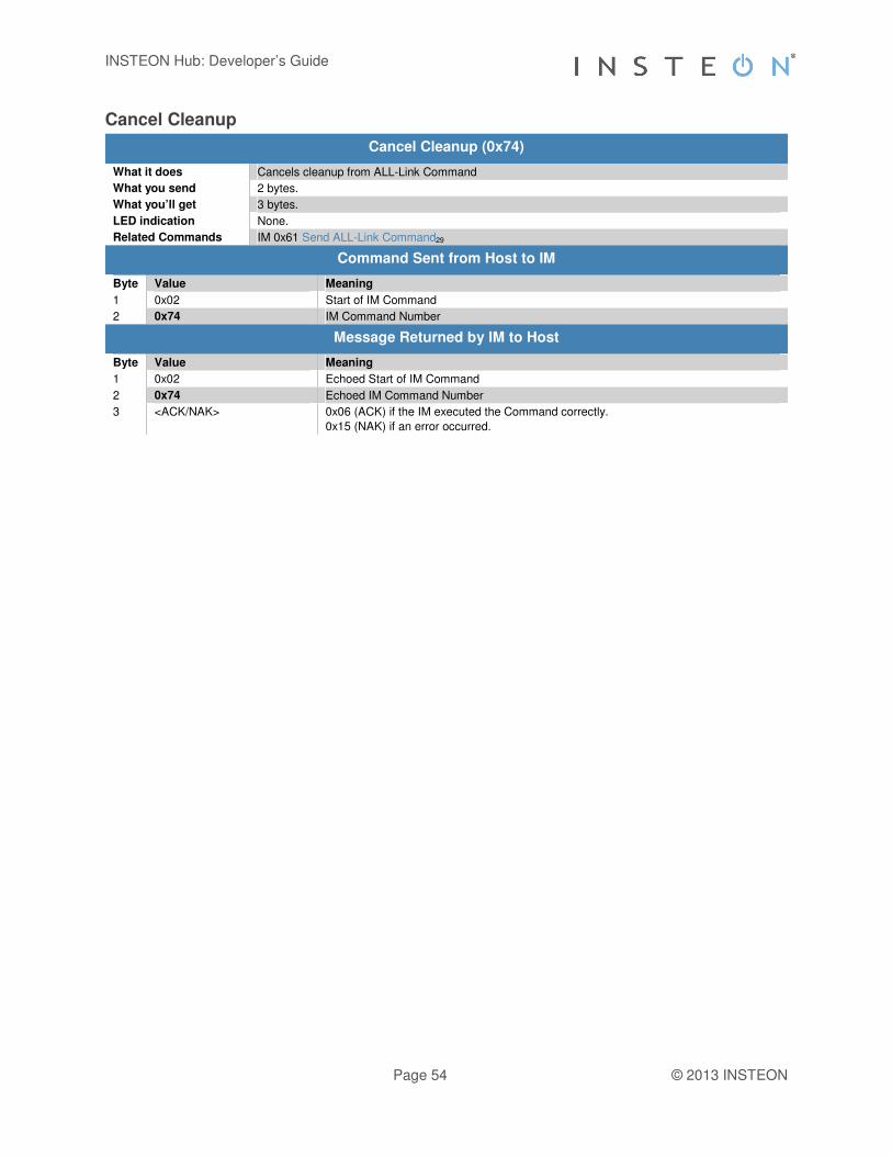
INSTEON Hub: Developer’s Guide
Page 54 © 2013 INSTEON
Cancel Cleanup
Cancel Cleanup (0x74)
What it does Cancels cleanup from ALL-Link Command
What you send 2 bytes.
What you’ll get 3 bytes.
LED indication None.
Related Commands IM 0x61 Send ALL-Link Command29
Command Sent from Host to IM
Byte Value Meaning
1 0x02 Start of IM Command
2 0x74 IM Command Number
Message Returned by IM to Host
Byte Value Meaning
1 0x02 Echoed Start of IM Command
2 0x74 Echoed IM Command Number
3 <ACK/NAK> 0x06 (ACK) if the IM executed the Command correctly.
0x15 (NAK) if an error occurred.