Installing Wilwood four-wheel disc brakes on a GMC … DENALI BRAKES Installing Wilwood four-wheel...
8
GMC DENALI BRAKES Installing Wilwood four-wheel disc brakes on a GMC Denali SUV A big vehicle such as this Denali requires large brakes, so a Wilwood part number 140-8992 front disc brake kit was ordered. The kit features huge 16- inch vented and slotted rotors with aluminum hats, TC 6R six-piston calipers, caliper brackets, BP-10 Smart Pads, and all of the hardware required to complete the installation. The Denali has an internal parking brake system so a Wilwood part number 140-8993 rear disc brake kit was ordered. The kit features 12.75-inch diameter drilled and slotted rotors with an internal parking brake drum, Superlite 4R calipers, caliper brackets, BP-10 Smart Pads and all of the hardware required to complete the installation. In the ‘70s and ‘80s there was a push for Americans to buy small cars. The auto manufacturers were downsizing the cars, and were trying to make them more economical and fuel-efficient. This push for small cars was basically due to government rules that were making the auto manufacturers meet the Corporate Average Fuel Economy (CAFÉ) standards. The problem was the majority of American car buyers didn’t want small cars, because they were slow and funny looking, and they could see that they weren’t safe in an accident. Flying in the face of Government intervention, the American Public decided to buy trucks and multi-passenger utility vehicles called SUVs, because they were big and safe. The car manufacturers saw this trend so they started making the SUVs very comfortable and equipped them with every luxury feature they could come up with. As this trend grew, many companies started making them bigger and bigger, and that also turned them into gas-guzzlers. The end result was the fuel economy went out the window. The Government ended up with exactly the opposite of what they wanted. Over time and due to higher gas prices, the SUV market came back to reality and the auto manufacturers started building smaller SUVs that looked terrific and were more economical to drive. General Motors in particular came out with a series of engines that produce plenty of horsepower, but are economical at the same time. Since GMC used the same corporate engine, they started refining their entries into the SUV market upscale from the Chevy and one of the really nice
Transcript of Installing Wilwood four-wheel disc brakes on a GMC … DENALI BRAKES Installing Wilwood four-wheel...
GMC DENALI BRAKESInstalling Wilwood four-wheel disc brakes on a GMC Denali SUV
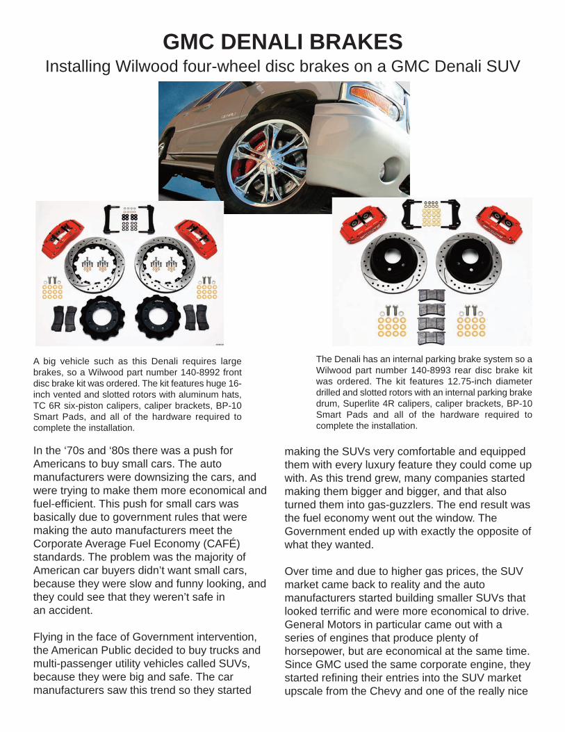
A big vehicle such as this Denali requires largebrakes, so a Wilwood part number 140-8992 frontdisc brake kit was ordered. The kit features huge 16-inch vented and slotted rotors with aluminum hats,TC 6R six-piston calipers, caliper brackets, BP-10Smart Pads, and all of the hardware required tocomplete the installation.
The Denali has an internal parking brake system so aWilwood part number 140-8993 rear disc brake kitwas ordered. The kit features 12.75-inch diameterdrilled and slotted rotors with an internal parking brakedrum, Superlite 4R calipers, caliper brackets, BP-10Smart Pads and all of the hardware required tocomplete the installation.
In the ‘70s and ‘80s there was a push forAmericans to buy small cars. The automanufacturers were downsizing the cars, andwere trying to make them more economical andfuel-efficient. This push for small cars wasbasically due to government rules that weremaking the auto manufacturers meet theCorporate Average Fuel Economy (CAFÉ)standards. The problem was the majority ofAmerican car buyers didn’t want small cars,because they were slow and funny looking, andthey could see that they weren’t safe in an accident.
Flying in the face of Government intervention,the American Public decided to buy trucks andmulti-passenger utility vehicles called SUVs,because they were big and safe. The carmanufacturers saw this trend so they started
making the SUVs very comfortable and equippedthem with every luxury feature they could come upwith. As this trend grew, many companies startedmaking them bigger and bigger, and that alsoturned them into gas-guzzlers. The end result wasthe fuel economy went out the window. TheGovernment ended up with exactly the opposite ofwhat they wanted.
Over time and due to higher gas prices, the SUVmarket came back to reality and the automanufacturers started building smaller SUVs thatlooked terrific and were more economical to drive.General Motors in particular came out with aseries of engines that produce plenty ofhorsepower, but are economical at the same time.Since GMC used the same corporate engine, theystarted refining their entries into the SUV marketupscale from the Chevy and one of the really nice

offerings is the Denali. It is a luxury offering that isbig enough to be safe and small enough to haverespectable fuel economy.
The Denali has a powerful engine combined withgood handling for a vehicle of this size, so it hasbecome popular with SUV buyers. The owner of theDenali in this story was pleased with his vehicle, buthe felt the brakes could be improved. There wasalso a second reason for a brake change becausehe just installed large diameter wheels and the largewindows in the wheels made the old unattractivebrakes very visible. He was aware that Wilwoodbrakes could improve the Denali’s stopping powerplus they would look nice behind the wheels.
The owner of this Denali contacted his Wilwooddealer and ordered a Wilwood part number 140-8992 front brake kit that features 16-inch diameterrotors and TC 6R calipers. The rear brakes feature12.75-inch diameter rotors with Superlite 4Rcalipers. The brake lines were also needed so heordered Wilwood part number 220-8998 stainlesssteel braided front lines and 220-8999 stainless steelbraided rear lines.
Wilwood Engineering recommends that someoneexperienced and competent in the installation andmaintenance of disc brakes should only install thedisc brakes. It would be a good idea to spread outthe brake kit and make sure the parts you havematch the parts list on the instruction sheet. It is alsoimportant to make sure the kit you have is thecorrect one for your particular application. If you aremechanically inclined, work on your own vehicle andhave brake installation experience you can probablydo this installation at home. You will also need anadequate variety of tools such as a floor jack andjack stands, an impact gun, a good assortment ofSAE and Metric wrenches and sockets, linewrenches, a foot-pound and an inch-pound torquewrench. It would also be advisable to have a bottleof Loctite 271, PTFE Thread Tape and Wilwood Hi-Temp 570 Racing Brake Fluid or Wilwood EXP 600Plus Hi-Temp Racing Brake Fluid. We are going toshow you how this installation is done so you candecide for yourself if you can perform it yourself or ifit would be better to have a professional do it foryou.
The Denali was raised up on a floor jack and then jackstands were installed underneath for safety. The hubcapswere removed and the lug nuts were disconnected withan impact gun and the correct size socket. After the lugnuts were disconnected, the large wheels and tires wereremoved.
The Denali was raised up on a floor jack and then jackstands were installed underneath for safety. Thehubcaps were removed and the lug nuts weredisconnected with an impact gun and the correct sizesocket. After the lug nuts were disconnected, the largewheels and tires were removed.
Before the rotor could be removed, the brake linebrackets had to be disconnected. Here one of the smallbrackets was disconnected from the A-arm assembly. Itis important to keep the brackets because they will bereused later.

There is another hose bracket located on the top of thespindle. Using a T-handle and a small socket, theretaining bolt was disconnected from the spindle. Thisbracket will also be reused later.
Using a ratchet wrench and the correct size socket, theCaliper bolts were removed from the original bracketassembly. A breaker bar may be necessary to break thebolts loose.
The caliper was lifted off of the rotor and was set to theside for now. It will be completely removed after therubber line is disconnected from the steel line.
The rotor was lifted off of the hub assembly and wasremoved from the car.
A M14-2.00 bolt outfitted with a M14 lock washer wasplaced through the hole in original caliper mounting earand it was loaded with a 0.029-inch thick washer and athin shim washer in preparation for mounting thecaliper.
Here is the caliper mounting bracket after it was boltedto the original caliper mounting ears. Shims can beadded between the bracket and mounting ears tocenter the caliper over the rotor.
The hard brake line was removed from the rubber hoseusing a line wrench. The line was loosened but it wasn’tremoved yet.
After the hard line was loosened from the rubber line,the spring clip retainer was removed.
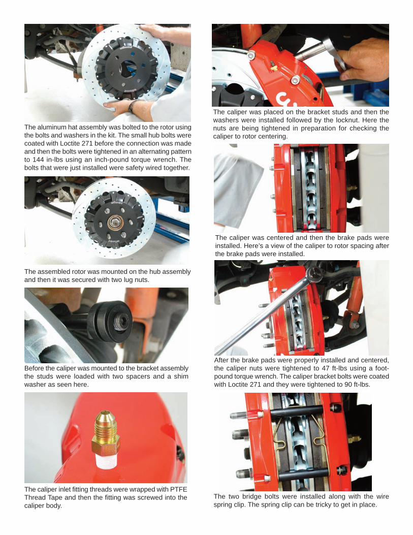
The aluminum hat assembly was bolted to the rotor usingthe bolts and washers in the kit. The small hub bolts werecoated with Loctite 271 before the connection was madeand then the bolts were tightened in an alternating patternto 144 in-lbs using an inch-pound torque wrench. Thebolts that were just installed were safety wired together.
The assembled rotor was mounted on the hub assemblyand then it was secured with two lug nuts.
Before the caliper was mounted to the bracket assemblythe studs were loaded with two spacers and a shimwasher as seen here.
The caliper inlet fitting threads were wrapped with PTFEThread Tape and then the fitting was screwed into thecaliper body.
The caliper was placed on the bracket studs and then thewashers were installed followed by the locknut. Here thenuts are being tightened in preparation for checking thecaliper to rotor centering.
The caliper was centered and then the brake pads wereinstalled. Here’s a view of the caliper to rotor spacing afterthe brake pads were installed.
After the brake pads were properly installed and centered,the caliper nuts were tightened to 47 ft-lbs using a foot-pound torque wrench. The caliper bracket bolts were coatedwith Loctite 271 and they were tightened to 90 ft-lbs.
The two bridge bolts were installed along with the wirespring clip. The spring clip can be tricky to get in place.
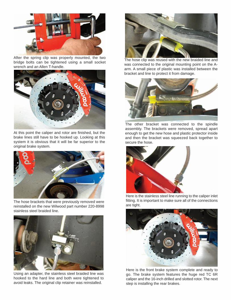
After the spring clip was properly mounted, the twobridge bolts can be tightened using a small socketwrench and an Allen T-handle.
At this point the caliper and rotor are finished, but thebrake lines still have to be hooked up. Looking at thissystem it is obvious that it will be far superior to theoriginal brake system.
The hose brackets that were previously removed werereinstalled on the new Wilwood part number 220-8998stainless steel braided line.
Using an adapter, the stainless steel braided line washooked to the hard line and both were tightened toavoid leaks. The original clip retainer was reinstalled.
The hose clip was reused with the new braided line andwas connected to the original mounting point on the A-arm. A small piece of plastic was installed between thebracket and line to protect it from damage.
The other bracket was connected to the spindleassembly. The brackets were removed, spread apartenough to get the new hose and plastic protector insideand then the bracket was squeezed back together tosecure the hose.
Here is the stainless steel line running to the caliper inletfitting. It is important to make sure all of the connectionsare tight.
Here is the front brake system complete and ready togo. The brake system features the huge red TC 6Rcaliper and the 16-inch drilled and slotted rotor. The nextstep is installing the rear brakes.

The front of the car was placed back on the groundand the rear was lifted and jack stands were placedunderneath for safety. The hubcaps were removedand then the lug nuts were disconnected. After the lugnuts were disconnected the tires and wheels wereremoved.
Using a breaker bar and the correct size socket, thecaliper bolts were removed.
After the bolts were disconnected, the caliper couldbe removed from the bracket. For now the caliperwas just moved out of the way while the new brakeswere installed.
The heavy rotor was lifted off of the axle studs. Youcan see the original caliper in the background. It willbe removed when the new lines are being installed.
Here is a close look at the internal parking brakeassembly. This is a useful assembly so it will be retained,which means the original parking brake cables remainintact.
The caliper will be mounted to the original calipermounting ears using a pair of M-14-2.00 x 40 mm boltsloaded with M14 I.D. x 21mm O.D. lock washers. After thebolts pass through the bracket they should be loaded witha 0.029-inch thick washer before the connection is made.
The bolts were installed finger tight and then they weretightened with a socket wrench to check the caliper to rotorcentering.
The Wilwood drilled and slotted rotor was installed on theaxle flange and was pushed back to mount it on thecentering ring. If you look close you can see the caliperbracket mounting studs in the background. This rotor hasan internal drum assembly for the parking brakeassembly.
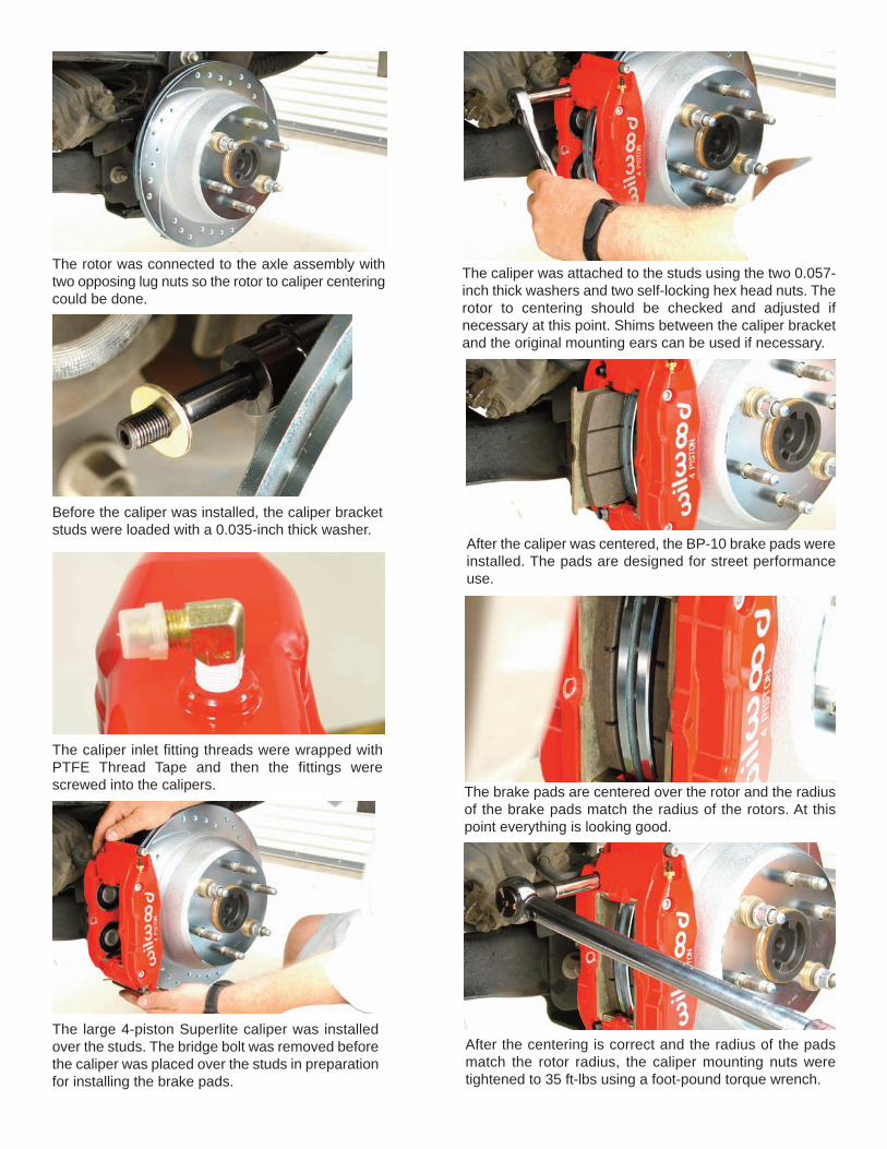
The rotor was connected to the axle assembly withtwo opposing lug nuts so the rotor to caliper centeringcould be done.
Before the caliper was installed, the caliper bracketstuds were loaded with a 0.035-inch thick washer.
The caliper inlet fitting threads were wrapped withPTFE Thread Tape and then the fittings werescrewed into the calipers.
The large 4-piston Superlite caliper was installedover the studs. The bridge bolt was removed beforethe caliper was placed over the studs in preparationfor installing the brake pads.
The caliper was attached to the studs using the two 0.057-inch thick washers and two self-locking hex head nuts. Therotor to centering should be checked and adjusted ifnecessary at this point. Shims between the caliper bracketand the original mounting ears can be used if necessary.
After the caliper was centered, the BP-10 brake pads wereinstalled. The pads are designed for street performanceuse.
The brake pads are centered over the rotor and the radiusof the brake pads match the radius of the rotors. At thispoint everything is looking good.
After the centering is correct and the radius of the padsmatch the rotor radius, the caliper mounting nuts weretightened to 35 ft-lbs using a foot-pound torque wrench.

Now the caliper mounting bracket bolts were tightened to90 ft-lbs using a foot-pound torque wrench.
The caliper center bridge pad retainer bolt wasreinstalled and it was tightened with a small socketwrench and a T-handle.
Here is the finished brake assembly featuring the redSuperlite four-piston caliper and the drilled and slottedrotor.
The hose connection was made from the caliper to thehard line. At this point the old caliper can be removed.The brake system will require bleeding and the pads willhave to be bedded in.
The Denali looks terrific with the large diameter wheel and lowprofile tires. The brakes add to the truck appearance and it stopsbetter than ever.
Wilwood Brakes4700 Calle Bolero
Camarillo, CA 93012(805) 388-1188
www.wilwood.comCopyright © 2010 Wilwood Engineering, Inc. -
All Rights Reserved