1 Introduction to TCP/IP. 2 Agenda What Is TCP/IP? IP Addressing.
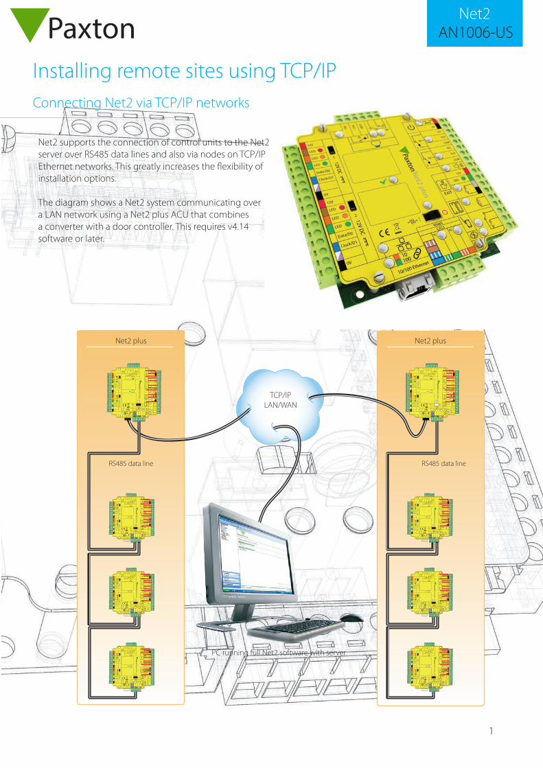
Installing remote sites using TCP/IPConnecting Net2 via TCP/IP networks
Net2 supports the connection of control units to the Net2 server over RS485 data lines and also via nodes on TCP/IP Ethernet networks. This greatly increases the flexibility of installation options.
The diagram shows a Net2 system communicating over a LAN network using a Net2 plus ACU that combines a converter with a door controller. This requires v4.14 software or later.
1r e
dae
R
:n o
itua
Cyl
n osr
edae
rC
DV2
1ro
F
2re
dae
R
12V
Red LED
Amber LED
Green LED
Data/D0
Clock/D1
Media Detect
0V
12V
Red LED
Amber LED
Green LED
Data/D0
Clock/D1
Media Detect
0V
N.C.
N.O.
COM
N.C.
N.O.
COM
Alarm
12V
Green LED
Exit
0VstupnIstuptu
Or e
woP 0V
12V
Contact
0V
0V
Tamper
PSU
repmaT/
USP
tcatnoC
nottuB
tixE2
y al eR
1ya le
R
Expansion
RxTx
RS485 NetworkCAT5 Cable Coding
nrG/
thW
erap
sr o
n eer
cS
a tad
mor f
s ero
cel
bac
neer
G
g nr
O /th
W
egna
rO
10/100 Ethernet
Server Connected
Server Link 10010
End of Line Termination
ON OFF
Net2 plus
PLACE SERIALNUMBER
LABEL HERE
Intruder Alarm
Set
V0mrA
esne
S
MO
C
.O.
N
0V0V
0V
0V
N.C.
N.O
2
COM
N.C.
N.O
COM
Data/D0
Clock/D1
CAT5 RS485
0V
10
TX RX
100
Data/D0
Clock/D1
10/100 Ethernet
N.C.
N.O
COM
12V - 24V
12V
1
2
12V
LED
LED
LED
12V
LED
LED
LED
LED
EXIT
12V DC
12V DC I
1PaxtonN
et2 plus
1r e
dae
R
:n o
itua
Cyl
n osr
edae
rC
DV2
1ro
F
2re
dae
R
12V
Red LED
Amber LED
Green LED
Data/D0
Clock/D1
Media Detect
0V
12V
Red LED
Amber LED
Green LED
Data/D0
Clock/D1
Media Detect
0V
N.C.
N.O.
COM
N.C.
N.O.
COM
Alarm
12V
Green LED
Exit
0VstupnIstuptu
Or e
woP 0V
12V
Contact
0V
0V
Tamper
PSU
repmaT/
USP
tcatnoC
nottuB
tixE2
y al eR
1ya le
R
Expansion
RxTx
RS485 NetworkCAT5 Cable Coding
nrG/
thW
erap
sr o
n eer
cS
a tad
mor f
s er o
cel
bac
neer
G
g nr
O /th
W
egna
rO
10/100 Ethernet
Server Connected
Server Link 10010
End of Line Termination
ON OFF
Net2 plus
PLACE SERIALNUMBER
LABEL HERE
Intruder Alarm
Set
V0mrA
esne
S
MO
C
.O.
N
0V0V
0V
0V
N.C.
N.O
2
COM
N.C.
N.O
COM
Data/D0
Clock/D1
CAT5 RS485
0V
10
TX RX
100
Data/D0
Clock/D1
10/100 Ethernet
N.C.
N.O
COM
12V - 24V
12V
1
2
12V
LED
LED
LED
12V
LED
LED
LED
LED
EXIT
12V DC
12V DC I
1PaxtonN
et2 plus
1r e
dae
R
:n o
itua
Cyl
n osr
edae
rC
DV2
1ro
F
2re
dae
R
12V
Red LED
Amber LED
Green LED
Data/D0
Clock/D1
Media Detect
0V
12V
Red LED
Amber LED
Green LED
Data/D0
Clock/D1
Media Detect
0V
N.C.
N.O.
COM
N.C.
N.O.
COM
Alarm
12V
Green LED
Exit
0V
stupnIstuptu
Or e
woP 0V
12V
Contact
0V
0V
Tamper
PSU
repmaT/
USP
tca tnoC
nottuB
ti xE2
y aleR
1ya le
R
Expansion
RxTx
RS485 NetworkCAT5 Cable Coding
nrG/
thW
erap
sr o
n ee r
cS
a tad
mor f
s er o
cel
bac
n eer
G
g nr
O /th
W
egna
rO
10/100 Ethernet
Server Connected
Server Link 10010
End of Line Termination
ON OFF
Net2 plus
PLACE SERIALNUMBER
LABEL HERE
Intruder Alarm
Set
V0mrA
esne
S
MO
C
.O.
N
0V0V
0V
0V
N.C.
N.O
2
COM
N.C.
N.O
COM
Data/D0
Clock/D1
CAT5 RS485
0V
10
TX RX
100
Data/D0
Clock/D1
10/100 EthernetN
.C.
N.O
COM
12V - 24V
12V
1
2
12V
LED
LED
LED
12V
LED
LED
LED
LED
EXIT
12V DC
12V DC I
1PaxtonN
et2 plus
1r e
dae
R
:n o
itua
Cyl
n osr
edae
rC
DV2
1ro
F
2re
dae
R
12V
Red LED
Amber LED
Green LED
Data/D0
Clock/D1
Media Detect
0V
12V
Red LED
Amber LED
Green LED
Data/D0
Clock/D1
Media Detect
0V
N.C.
N.O.
COM
N.C.
N.O.
COM
Alarm
12V
Green LED
Exit
0V
stupnIstu ptu
Or e
woP 0V
12V
Contact
0V
0V
Tamper
PSU
repmaT/
USP
tc a tnoC
nottuB
ti xE2
y al eR
1ya le
R
Expansion
RxTx
RS485 NetworkCAT5 Cable Coding
nrG/
thW
erap
sr o
n ee r
cS
a tad
mor f
s er o
cel
bac
n eer
G
g nr
O /th
W
egna
rO
10/100 Ethernet
Server Connected
Server Link 10010
End of Line Termination
ON OFF
Net2 plus
PLACE SERIALNUMBER
LABEL HERE
Intruder Alarm
Set
V0mrA
esne
S
MO
C
.O.
N
0V0V
0V
0V
N.C.
N.O
2
COM
N.C.
N.O
COM
Data/D0
Clock/D1
CAT5 RS485
0V
10
TX RX
100
Data/D0
Clock/D1
10/100 Ethernet
N.C.
N.O
COM
12V - 24V
12V
1
2
12V
LED
LED
LED
12V
LED
LED
LED
LED
EXIT
12V DC
12V DC I
1PaxtonN
et2 plus
Net2 plus Net2 plus
TCP/IP LAN/WAN
RS485 data line RS485 data line
PC running full Net2 software with server
AN1006-USNet2
1
2
AN1006-USNet2
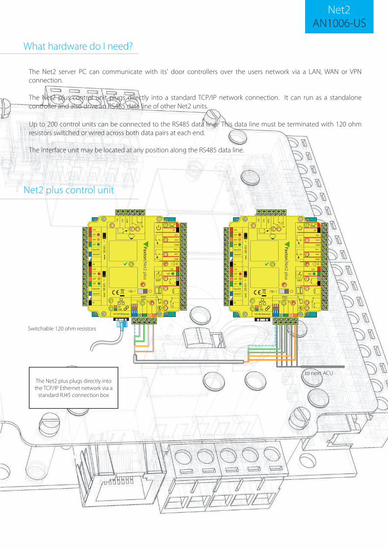
Up to 200 control units can be connected to the RS485 data line. This data line must be terminated with 120 ohm resistors switched or wired across both data pairs at each end.
The interface unit may be located at any position along the RS485 data line.
The Net2 server PC can communicate with its' door controllers over the users network via a LAN, WAN or VPN connection.
The Net2 plus control unit plugs directly into a standard TCP/IP network connection. It can run as a standalone controller and also drive an RS485 data line of other Net2 units.
What hardware do I need?
0V0V
0V
0V
N.C.
N.O
2
COM
N.C.
N.O
COM
Data/D0
Clock/D1
CAT5 RS485
0V
10
TX RX
100
Data/D0
Clock/D1
10/100 Ethernet
N.C.
N.O
COM
12V - 24V
12V
1
2
12V
LED
LED
LED
12V
LED
LED
LED
LED
EXIT 12V D
C 12V D
C I
1PaxtonN
et2 plus
0V0V
0V
0V
N.C.
N.O
2
COM
N.C.
N.O
COM
Data/D0
Clock/D1
CAT5 RS485
0V
10
TX RX
100
Data/D0
Clock/D1
10/100 Ethernet
N.C.
N.O
COM
12V - 24V
12V
1
2
12V
LED
LED
LED
12V
LED
LED
LED
LED
EXIT
12V DC
12V DC I
1PaxtonN
et2 plus
Net2 plus control unit
to next ACU
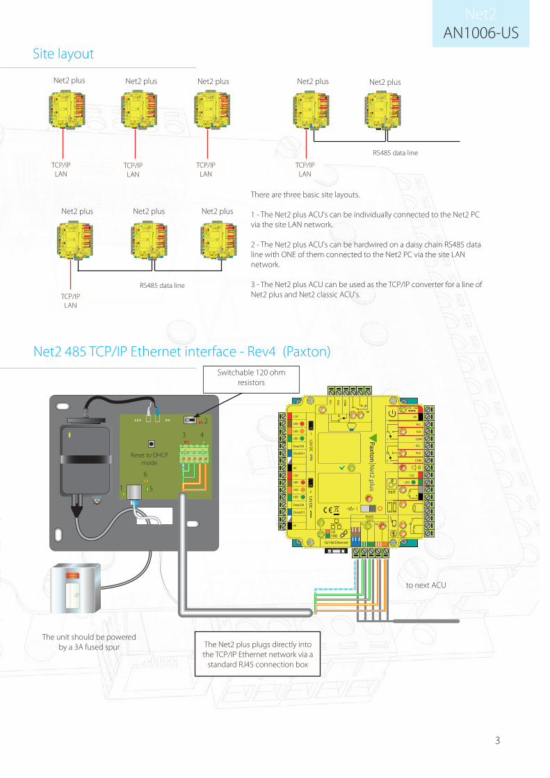
Switchable 120 ohm resistors
The Net2 plus plugs directly into the TCP/IP Ethernet network via a
standard RJ45 connection box
3
AN1006-USNet2
Site layout
Net2 plus Net2 plus
Net2 plus Net2 plus Net2 plus Net2 plus Net2 plus
TCP/IP LAN
TCP/IP LAN
TCP/IP LAN
TCP/IP LAN
TCP/IP LAN
There are three basic site layouts.
1 - The Net2 plus ACU's can be individually connected to the Net2 PC via the site LAN network.
2 - The Net2 plus ACU's can be hardwired on a daisy chain RS485 data line with ONE of them connected to the Net2 PC via the site LAN network.
3 - The Net2 plus ACU can be used as the TCP/IP converter for a line of Net2 plus and Net2 classic ACU's.
RS485 data line
RS485 data line
Net2 plus
0V12V
0V0V
0V
0V
N.C.
N.O
2
COM
N.C.
N.O
COM
Data/D0
Clock/D1
CAT5 RS485
0V
10
TX RX
100
Data/D0
Clock/D1
10/100 Ethernet
N.C.
N.O
COM
12V - 24V
12V
1
2
12V
LED
LED
LED
12V
LED
LED
LED
LED
EXIT
12V DC
12V DC I
1PaxtonN
et2 plus1
4
2
3
5
6
Reset to DHCP mode
The unit should be powered by a 3A fused spur
to next ACU
The Net2 plus plugs directly into the TCP/IP Ethernet network via a
standard RJ45 connection box
Switchable 120 ohm resistors
Net2 485 TCP/IP Ethernet interface - Rev4 (Paxton)
0V0V
0V
0V
N.C.
N.O
2
COM
N.C.
N.O
COM
Data/D0
Clock/D1
CAT5 RS485
0V
10
TX RX
100
Data/D0
Clock/D1
10/100 Ethernet
N.C.
N.O
COM
12V - 24V
12V
1
2
12V
LED
LED
LED
12V
LED
LED
LED
LED
EXIT
12V DC
12V DC I
1PaxtonN
et2 plus
0V0V
0V
0V
N.C.
N.O
2
COM
N.C.
N.O
COM
Data/D0
Clock/D1
CAT5 RS485
0V
10
TX RX
100
Data/D0
Clock/D1
10/100 Ethernet
N.C.
N.O
COM
12V - 24V
12V
1
2
12V
LED
LED
LED
12V
LED
LED
LED
LED
EXIT
12V DC
12V DC I
1PaxtonN
et2 plus
0V0V
0V
0V
N.C.
N.O
2
COM
N.C.
N.O
COM
Data/D0
Clock/D1
CAT5 RS485
0V
10
TX RX
100
Data/D0
Clock/D1
10/100 Ethernet
N.C.
N.O
COM
12V - 24V
12V
1
2
12V
LED
LED
LED
12V
LED
LED
LED
LED
EXIT
12V DC
12V DC I
1PaxtonN
et2 plus
0V0V
0V
0V
N.C.
N.O
2
COM
N.C.
N.O
COM
Data/D0
Clock/D1
CAT5 RS485
0V
10
TX RX
100
Data/D0
Clock/D1
10/100 Ethernet
N.C.
N.O
COM
12V - 24V
12V
1
2
12V
LED
LED
LED
12V
LED
LED
LED
LED
EXIT
12V DC
12V DC I
1PaxtonN
et2 plus
0V0V
0V
0V
N.C.
N.O
2
COM
N.C.
N.O
COM
Data/D0
Clock/D1
CAT5 RS485
0V
10
TX RX
100
Data/D0
Clock/D1
10/100 Ethernet
N.C.
N.O
COM
12V - 24V
12V
1
2
12V
LED
LED
LED
12V
LED
LED
LED
LED
EXIT
12V DC
12V DC I
1PaxtonN
et2 plus
0V0V
0V
0V
N.C.
N.O
2
COM
N.C.
N.O
COM
Data/D0
Clock/D1
CAT5 RS485
0V
10
TX RX
100
Data/D0
Clock/D1
10/100 Ethernet
N.C.
N.O
COM
12V - 24V
12V
1
2
12V
LED
LED
LED
12V
LED
LED
LED
LED
EXIT
12V DC
12V DC I
1PaxtonN
et2 plus
0V0V
0V
0V
N.C.
N.O
2
COM
N.C.
N.O
COM
Data/D0
Clock/D1
CAT5 RS485
0V
10
TX RX
100
Data/D0
Clock/D1
10/100 Ethernet
N.C.
N.O
COM
12V - 24V
12V
1
2
12V
LED
LED
LED
12V
LED
LED
LED
LED
EXIT
12V DC
12V DC I
1PaxtonN
et2 plus
0V0V
0V
0V
N.C.
N.O
2
COM
N.C.
N.O
COM
Data/D0
Clock/D1
CAT5 RS485
0V
10
TX RX
100
Data/D0
Clock/D1
10/100 Ethernet
N.C.
N.O
COM
12V - 24V
12V
1
2
12V
LED
LED
LED
12V
LED
LED
LED
LED
EXIT
12V DC
12V DC I
1PaxtonN
et2 plus

4
AN1006-USNet2
**IMPORTANT**Do NOT apply power before connecting the RJ45 plug
to a network point.
This device requires Net2 v4.07 or later to operate. Earlier Net2 software is not compatible with this unit. If your PC can only support Net2 v3
software, please contact Technical Support for further advice.
1. Power (Green) - 12V power LED.2. Termination (Red) - The on-board resistors are in place across the RS485 data pairs.3. Rx (Red) - The interface is receiving data (RS485).4. Tx (Green) - The interface is sending data (RS485).5. Server Connected (Green) - The TCP/IP interface is communicating with the PC Net2 server.6. Server Link Green = 100 Mbit/s : Orange = 10 Mbit/s (TCP/IP speed).
LED indications
The Net2 plus is configured using the Net2 Server Configuration Utility, by selecting the TCP/IP nodes tab. Depending on the specific details of the Ethernet network, you may be able to detect the Net2 plus, simply by clicking Detect. If this doesn't find it, then you will have to Click 'Add' and enter the IP Address manually.
The unit supports DHCP, which means that a DHCP server can issue its IP address. Alternatively, the IP address can be manually entered. The recommended method of obtaining an IP address is by DHCP. A reservation should be
Software configuration
5
AN1006-USNet2
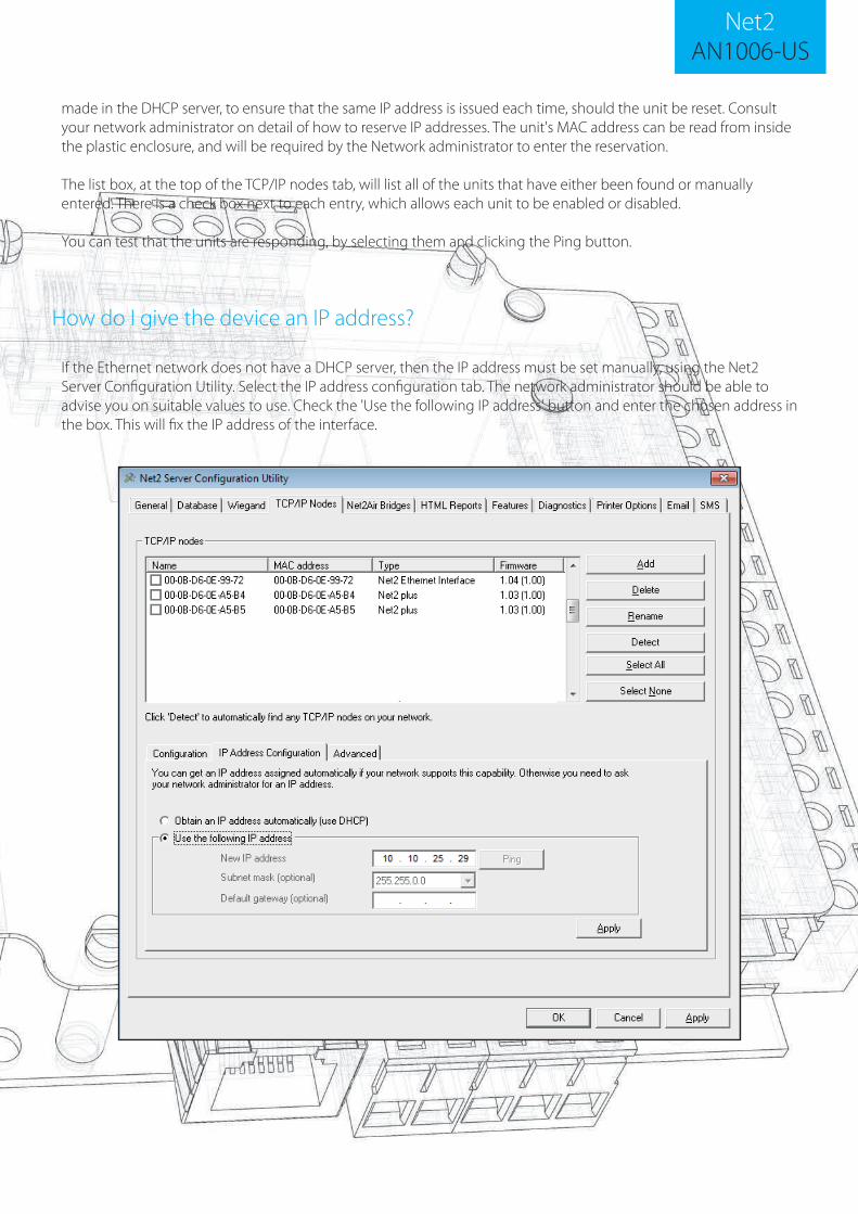
made in the DHCP server, to ensure that the same IP address is issued each time, should the unit be reset. Consult your network administrator on detail of how to reserve IP addresses. The unit's MAC address can be read from inside the plastic enclosure, and will be required by the Network administrator to enter the reservation.
The list box, at the top of the TCP/IP nodes tab, will list all of the units that have either been found or manually entered. There is a check box next to each entry, which allows each unit to be enabled or disabled.
You can test that the units are responding, by selecting them and clicking the Ping button.
If the Ethernet network does not have a DHCP server, then the IP address must be set manually, using the Net2 Server Configuration Utility. Select the IP address configuration tab. The network administrator should be able to advise you on suitable values to use. Check the 'Use the following IP address' button and enter the chosen address in the box. This will fix the IP address of the interface.
How do I give the device an IP address?
6
AN1006-USNet2
The rename button can be used to give an interface a meaningful name in the system. This can be especially useful when more than one interface is used, as the name will appear in the doors screen within Net2 showing which ACU's are connected to which data line, helping in any future fault finding process.
Naming TCP/IP Ethernet interfaces
Network latency can be amended for sites with slow or busy TCP/IP networks. The advanced options should only be changed following advice from Paxton Technical Support
Advanced tab of config utility
Connection over a Wide-Area Network (WAN)
If you are connecting the interface to a WAN or to a network with a different subnet, you must first fix the remote IP address, subnet mask and return gateway in the unit before taking it to the remote site.
The PC that has the Net2 server installed must be able to access the IP address range on the WAN\remote site. This may require the routers and gateways to be configured between the networks. Again, this would be done by the I.T\Network administrator of that site.
Once installed, use the Add button to create a record in the nodes table (if none was created during initial set-up) and you should then be able to detect its MAC by entering the IP address in the Configuration screen Ping box.
On sites with high levels of broadcast traffic (CCTV, etc) this option is highly recommended and should be implemented wherever possible. VLAN's allow administrators to set up their networks by logically grouping devices. IP addresses, subnet masks, and local network protocols require fewer local server resources in this environment. Services can be more effectively deployed when they span buildings within a single VLAN. See also: AN1085 - Recommendations for using Net2 with LAN and WAN networks. < http://paxton.info/970 >
VLAN recommended
Connecting to the PC directly
If you detect the MAC address but the device now shows 'Not Responding', check the IP address to make sure it is still in range with the PC or network. If it is not, you should either change the PC's IP address or the Ethernet interface's IP address so they are both again in the same range. Our Technical team can talk you through this if you need help.
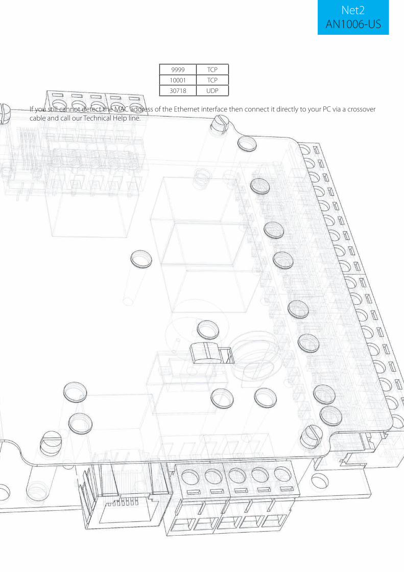
If the MAC address does not appear when you click 'Detect' then you will need to check that the following ports are open:-
Troubleshooting
The Net2 plus unit can be connected to the PC via a standard network patch cable.
7
AN1006-USNet2
If you still cannot detect the MAC address of the Ethernet interface then connect it directly to your PC via a crossover cable and call our Technical Help line.
9999 TCP
10001 TCP
30718 UDP