Installing and Removing SFP and XFP Modules - cisco.com€¦ · † Actuator Button SFP Module,...
16
CHAPTER 5-1 Cisco 7600 Series Ethernet Services Plus Line Card Hardware Installation Guide OL-16146-10 5 Installing and Removing SFP and XFP Modules This chapter describes how to install or remove small form-factor pluggable (SFP modules or XFP modules) on the Cisco 7600 Series Ethernet Services + line cards. This chapter contains the following sections: • Removing and Installing SFP Modules, page 5-1 • Removing and Installing XFP Modules, page 5-11 Removing and Installing SFP Modules Note The Cisco 7600 ES+ will only accept the SFP modules listed as supported in this document. An SFP check is run every time an SFP module is inserted into a Cisco 7600 ES+ and only SFP modules that pass this check are usable. Before you remove or install an SFP module, read the installation information in this section and the “Laser/LED Safety” section on page 3-8. Caution Protect the SFP modules by inserting clean dust covers into them after the cables are removed. Be sure to clean the optic surfaces of the fiber cables before you plug them back into the optical ports of another SFP module. Avoid getting dust and other contaminants into the optical ports of your SFP modules, because the optics will not work correctly when obstructed with dust. Caution It is strongly recommended that you do not install or remove the SFP module with fiber-optic cables attached to it because of the potential of damaging the cable, the cable connector, or the optical interfaces in the SFP module. Disconnect all cables before removing or installing an SFP module. Removing and inserting an SFP module can shorten its useful life, so you should not remove and insert SFP modules any more often than is absolutely necessary. SFP modules use one of four different latching devices to install and remove the module from a port. The four types of SFP module latching devices are described in the following sections: • Bale Clasp SFP Module, page 5-2 • Mylar Tab SFP Module, page 5-4
Transcript of Installing and Removing SFP and XFP Modules - cisco.com€¦ · † Actuator Button SFP Module,...
Cisco 7600 Series Ethernet SOL-16146-10
C H A P T E R 5
Installing and Removing SFP and XFP ModulesThis chapter describes how to install or remove small form-factor pluggable (SFP modules or XFP modules) on the Cisco 7600 Series Ethernet Services + line cards. This chapter contains the following sections:
• Removing and Installing SFP Modules, page 5-1
• Removing and Installing XFP Modules, page 5-11
Removing and Installing SFP Modules
Note The Cisco 7600 ES+ will only accept the SFP modules listed as supported in this document. An SFP check is run every time an SFP module is inserted into a Cisco 7600 ES+ and only SFP modules that pass this check are usable.
Before you remove or install an SFP module, read the installation information in this section and the “Laser/LED Safety” section on page 3-8.
Caution Protect the SFP modules by inserting clean dust covers into them after the cables are removed. Be sure to clean the optic surfaces of the fiber cables before you plug them back into the optical ports of another SFP module. Avoid getting dust and other contaminants into the optical ports of your SFP modules, because the optics will not work correctly when obstructed with dust.
Caution It is strongly recommended that you do not install or remove the SFP module with fiber-optic cables attached to it because of the potential of damaging the cable, the cable connector, or the optical interfaces in the SFP module. Disconnect all cables before removing or installing an SFP module.
Removing and inserting an SFP module can shorten its useful life, so you should not remove and insert SFP modules any more often than is absolutely necessary.
SFP modules use one of four different latching devices to install and remove the module from a port. The four types of SFP module latching devices are described in the following sections:
• Bale Clasp SFP Module, page 5-2
• Mylar Tab SFP Module, page 5-4
5-1ervices Plus Line Card Hardware Installation Guide
Chapter 5 Installing and Removing SFP and XFP Modules Removing and Installing SFP Modules
• Actuator Button SFP Module, page 5-6
• Slide Tab SFP Module, page 5-8
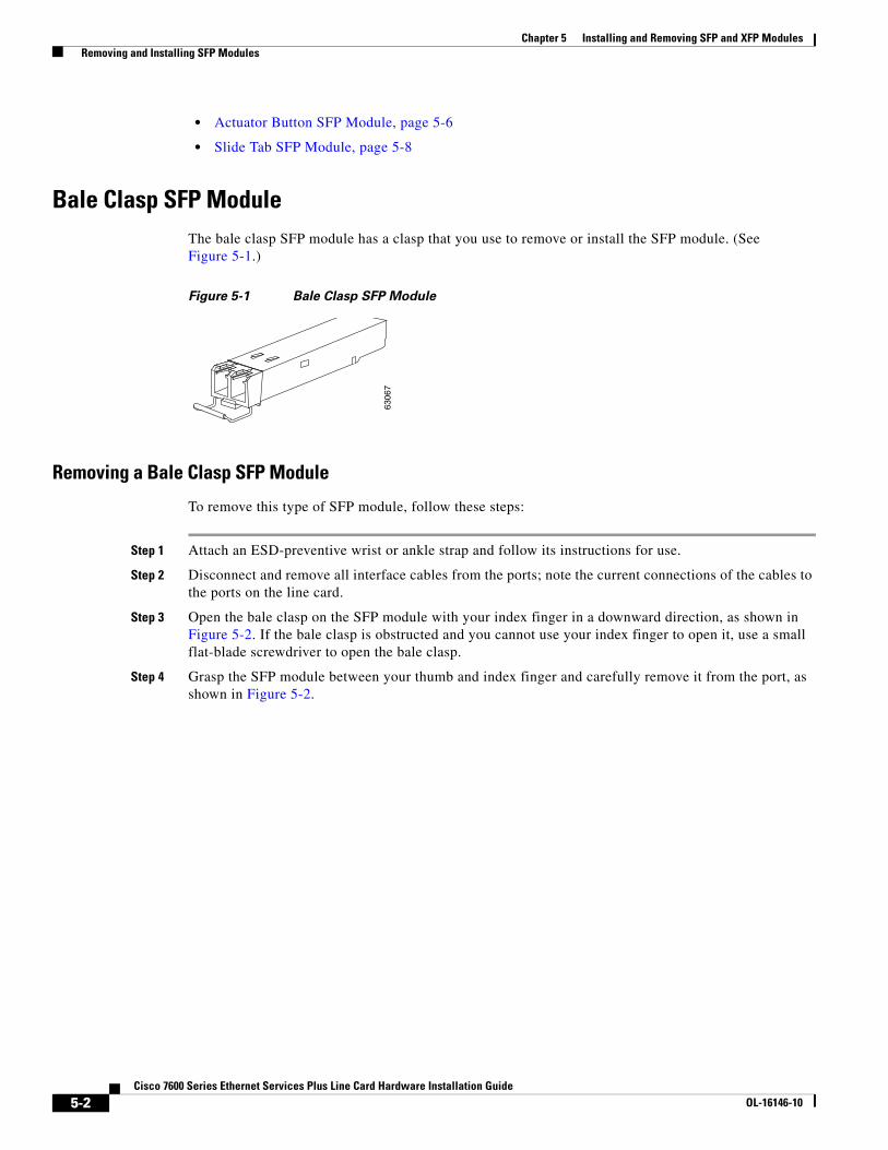
Bale Clasp SFP ModuleThe bale clasp SFP module has a clasp that you use to remove or install the SFP module. (See Figure 5-1.)
Figure 5-1 Bale Clasp SFP Module
Removing a Bale Clasp SFP Module
To remove this type of SFP module, follow these steps:
Step 1 Attach an ESD-preventive wrist or ankle strap and follow its instructions for use.
Step 2 Disconnect and remove all interface cables from the ports; note the current connections of the cables to the ports on the line card.
Step 3 Open the bale clasp on the SFP module with your index finger in a downward direction, as shown in Figure 5-2. If the bale clasp is obstructed and you cannot use your index finger to open it, use a small flat-blade screwdriver to open the bale clasp.
Step 4 Grasp the SFP module between your thumb and index finger and carefully remove it from the port, as shown in Figure 5-2.
6306
7
5-2Cisco 7600 Series Ethernet Services Plus Line Card Hardware Installation Guide
OL-16146-10

Chapter 5 Installing and Removing SFP and XFP Modules Removing and Installing SFP Modules
Figure 5-2 Removing a Bale Clasp SFP Module
Step 5 Place the removed SFP module on an antistatic mat, or immediately place it in a static shielding bag if you plan to return it to the factory.
Step 6 Protect your line card by inserting clean SFP module cage covers into the optical module cage when there is no SFP module installed.
Installing a Bale Clasp SFP Module
To install this type of SFP module, follow these steps:
Step 1 Attach an ESD-preventive wrist or ankle strap and follow its instructions for use.
7600-ES+ 20G3CXL
ETHERNET SERVICES MODULE
STATUS
1
2
35
79
46
810
7600-ES+ 20G3CXL
STATUS
1
2
35
79
46
810
7600-ES+ 20G3CXL
ETHERNET SERVICES MODULE
STATUS
1
2
35
79
46
810
7600-ES+ 20G3CXL
STATUS
1
2
35
79
46
810
2808
65
5-3Cisco 7600 Series Ethernet Services Plus Line Card Hardware Installation Guide
OL-16146-10

Chapter 5 Installing and Removing SFP and XFP Modules Removing and Installing SFP Modules
Step 2 Close the bale clasp before inserting the SFP module.
Step 3 Line up the SFP module with the port and slide it into the port. (See Figure 5-3.)
Figure 5-3 Installing a Bale Clasp SFP Module into a Port
Note Verify that the SFP modules are completely seated and secured in their assigned receptacles on the line card by firmly pushing on each SFP module. If the SFP module is not completely seated and secured in the receptacle, you will hear a click as the triangular pin on the bottom of the SFP module snaps into the hole in the receptacle.
Mylar Tab SFP ModuleThe mylar tab SFP module has a tab that you pull to remove the module from a port. (See Figure 5-4.)
Figure 5-4 Mylar Tab SFP Module
Removing a Mylar Tab SFP Module
To remove this type of SFP module, follow these steps:
Step 1 Attach an ESD-preventive wrist or ankle strap and follow its instructions for use.
7600-ES+ 20G3CXL
ETHERNET SERVICES MODULE
STATUS
EXT CLK
1
2
35
79
46
810
7600-ES+ 20G3CXL
STATUS
EXT CLK
1
2
35
79
46
810
2808
64
6306
5
5-4Cisco 7600 Series Ethernet Services Plus Line Card Hardware Installation Guide
OL-16146-10
Chapter 5 Installing and Removing SFP and XFP Modules Removing and Installing SFP Modules
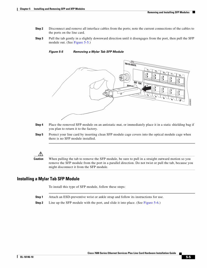
Step 2 Disconnect and remove all interface cables from the ports; note the current connections of the cables to the ports on the line card.
Step 3 Pull the tab gently in a slightly downward direction until it disengages from the port, then pull the SFP module out. (See Figure 5-5.)
Figure 5-5 Removing a Mylar Tab SFP Module
Step 4 Place the removed SFP module on an antistatic mat, or immediately place it in a static shielding bag if you plan to return it to the factory.
Step 5 Protect your line card by inserting clean SFP module cage covers into the optical module cage when there is no SFP module installed.
Caution When pulling the tab to remove the SFP module, be sure to pull in a straight outward motion so you remove the SFP module from the port in a parallel direction. Do not twist or pull the tab, because you might disconnect it from the SFP module.
Installing a Mylar Tab SFP Module
To install this type of SFP module, follow these steps:
Step 1 Attach an ESD-preventive wrist or ankle strap and follow its instructions for use.
Step 2 Line up the SFP module with the port, and slide it into place. (See Figure 5-6.)
7600-ES+ 20G3CXL
ETHERNET SERVICES MODULE
STATUS
EXT CLK
1
2
35
79
46
810
7600-ES+ 20G3CXL
STATUS
EXT CLK
1
2
35
79
46
810
STATUS
2808
60
5-5Cisco 7600 Series Ethernet Services Plus Line Card Hardware Installation Guide
OL-16146-10

Chapter 5 Installing and Removing SFP and XFP Modules Removing and Installing SFP Modules
Figure 5-6 Installing a Mylar Tab SFP Module
Note Verify that the SFP modules are completely seated and secured in their assigned receptacles on the line card by firmly pushing on each SFP module. If the SFP module is not completely seated and secured in the receptacle, you will hear a click as the triangular pin on the bottom of the SFP module snaps into the hole in the receptacle.
Actuator Button SFP ModuleThe actuator button SFP module includes a button that you push in order to remove the SFP module from a port. (See Figure 5-7.)
Figure 5-7 Actuator Button SFP Module
Removing an Actuator Button SFP Module
To remove this type of SFP module, follow these steps:
Step 1 Attach an ESD-preventive wrist or ankle strap and follow its instructions for use.
Step 2 Disconnect and remove all interface cables from the ports; note the current connections of the cables to the ports on the line card.
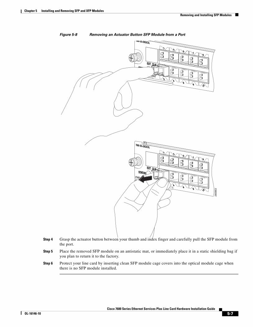
Step 3 Gently press the actuator button on the front of the SFP module until it clicks and the latch mechanism activates, releasing the SFP module from the port. (See Figure 5-8.)
ETHERNET SERVICES MODULE
STATUS
EXT CLK
1
2
35
79
46
810
STATUS
EXT CLK
1
2
35
79
46
810
STATUS
2808
61
6306
6
5-6Cisco 7600 Series Ethernet Services Plus Line Card Hardware Installation Guide
OL-16146-10
Chapter 5 Installing and Removing SFP and XFP Modules Removing and Installing SFP Modules
Figure 5-8 Removing an Actuator Button SFP Module from a Port
Step 4 Grasp the actuator button between your thumb and index finger and carefully pull the SFP module from the port.
Step 5 Place the removed SFP module on an antistatic mat, or immediately place it in a static shielding bag if you plan to return it to the factory.
Step 6 Protect your line card by inserting clean SFP module cage covers into the optical module cage when there is no SFP module installed.
7600-ES+ 20G3CXL
ETHERNET SERVICES MODULE
STATUS
EXT CLK
1
2
35
79
46
810
7600-ES+ 20G3CXL
STATUS
EXT CLK
1
2
35
79
46
810
7600-ES+ 20G3CXL
ETHERNET SERVICES MODULE
STATUS
EXT CLK
1
2
35
79
46
810
7600-ES+ 20G3CXL
STATUS
EXT CLK
1
2
35
79
46
810
2808
63
5-7Cisco 7600 Series Ethernet Services Plus Line Card Hardware Installation Guide
OL-16146-10

Chapter 5 Installing and Removing SFP and XFP Modules Removing and Installing SFP Modules
Installing an Actuator Button SFP Module
To install this type of SFP module, follow these steps:
Step 1 Attach an ESD-preventive wrist or ankle strap and follow its instructions for use.
Step 2 Line up the SFP module with the port and slide it in until the actuator button clicks into place. (See Figure 5-9.) Be sure not to press the actuator button as you insert the SFP module because you might inadvertently disengage the SFP module from the port.
Figure 5-9 Installing an Actuator Button SFP Module
Note Verify that the SFP modules are completely seated and secured in their assigned receptacles on the line card by firmly pushing on each SFP module. If the SFP module is not completely seated and secured in the receptacle, you will hear a click as the triangular pin on the bottom of the SFP module snaps into the hole in the receptacle.
Slide Tab SFP ModuleThe slide tab SFP module has a tab underneath the front of the SFP module that you use to disengage the module from a port. (See Figure 5-10.)
Figure 5-10 Slide Tab SFP Module
7600-ES+ 20G3CXL
ETHERNET SERVICES MODULE
STATUS
EXT CLK
1
2
35
79
46
810
7600-ES+ 20G3CXL
STATUS
EXT CLK
1
2
35
79
46
810
2808
62
8465
1
5-8Cisco 7600 Series Ethernet Services Plus Line Card Hardware Installation Guide
OL-16146-10
Chapter 5 Installing and Removing SFP and XFP Modules Removing and Installing SFP Modules
Removing a Slide Tab SFP Module
To remove this type of SFP module, follow these steps:
Step 1 Attach an ESD-preventive wrist or ankle strap and follow its instructions for use.
Step 2 Disconnect and remove all interface cables from the ports; note the current connections of the cables to the ports on the line card.
Step 3 Grasp the SFP module between your thumb and index finger.
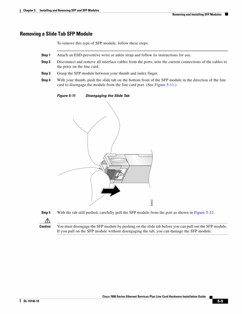
Step 4 With your thumb, push the slide tab on the bottom front of the SFP module in the direction of the line card to disengage the module from the line card port. (See Figure 5-11.)
Figure 5-11 Disengaging the Slide Tab
Step 5 With the tab still pushed, carefully pull the SFP module from the port as shown in Figure 5-12.
Caution You must disengage the SFP module by pushing on the slide tab before you can pull out the SFP module. If you pull on the SFP module without disengaging the tab, you can damage the SFP module.
8465
2
5-9Cisco 7600 Series Ethernet Services Plus Line Card Hardware Installation Guide
OL-16146-10
Chapter 5 Installing and Removing SFP and XFP Modules Removing and Installing SFP Modules
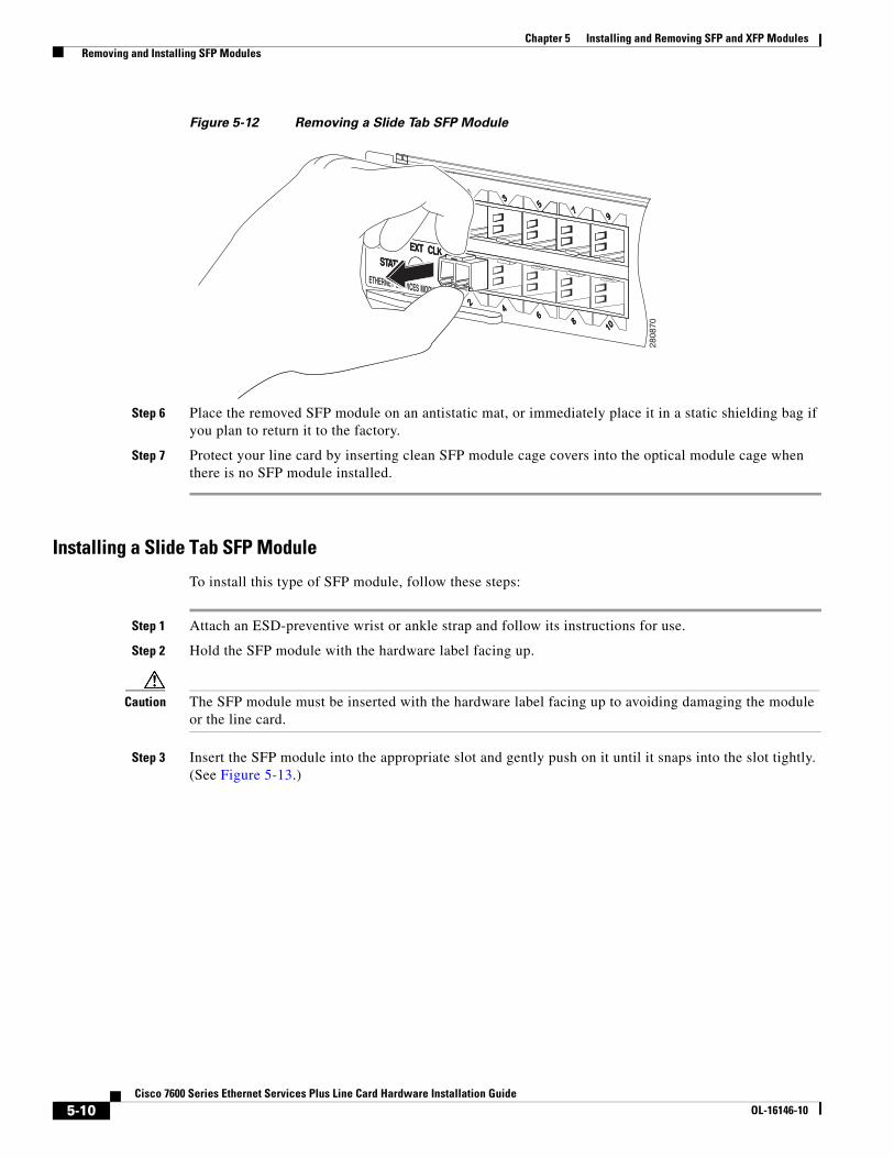
Figure 5-12 Removing a Slide Tab SFP Module
Step 6 Place the removed SFP module on an antistatic mat, or immediately place it in a static shielding bag if you plan to return it to the factory.
Step 7 Protect your line card by inserting clean SFP module cage covers into the optical module cage when there is no SFP module installed.
Installing a Slide Tab SFP Module
To install this type of SFP module, follow these steps:
Step 1 Attach an ESD-preventive wrist or ankle strap and follow its instructions for use.
Step 2 Hold the SFP module with the hardware label facing up.
Caution The SFP module must be inserted with the hardware label facing up to avoiding damaging the module or the line card.
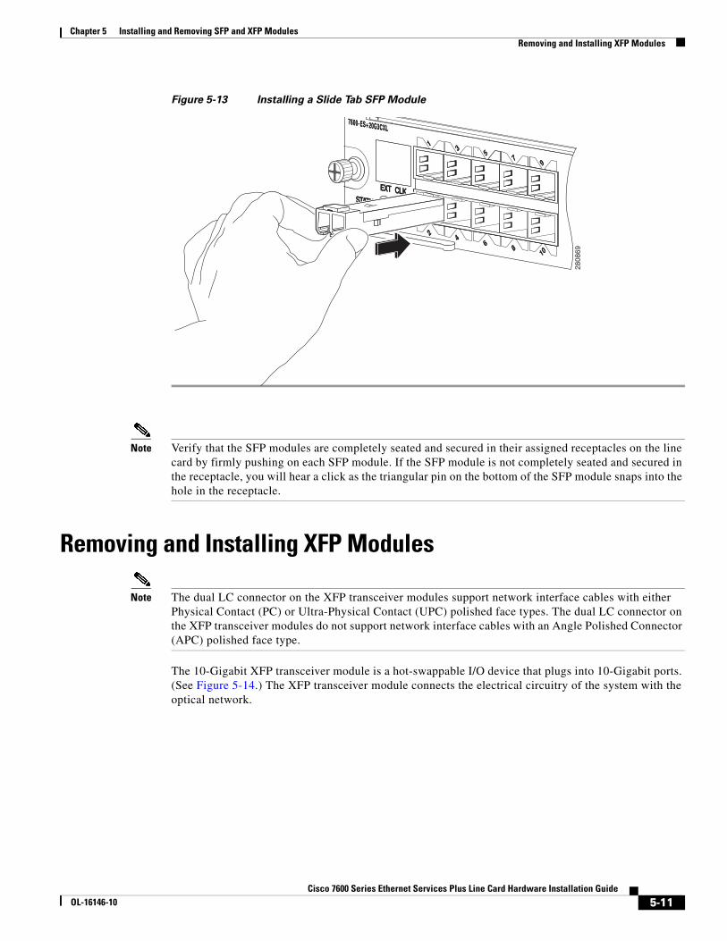
Step 3 Insert the SFP module into the appropriate slot and gently push on it until it snaps into the slot tightly. (See Figure 5-13.)
7600-ES+ 20G3CXL
ETHERNET SERVICES MODULE
STATUS
EXT CLK
1
2
35
79
46
810
7600-ES+ 20G3CXL
STATUS
EXT CLK
1
2
35
79
46
810
2808
70
5-10Cisco 7600 Series Ethernet Services Plus Line Card Hardware Installation Guide
OL-16146-10
Chapter 5 Installing and Removing SFP and XFP Modules Removing and Installing XFP Modules
Figure 5-13 Installing a Slide Tab SFP Module
Note Verify that the SFP modules are completely seated and secured in their assigned receptacles on the line card by firmly pushing on each SFP module. If the SFP module is not completely seated and secured in the receptacle, you will hear a click as the triangular pin on the bottom of the SFP module snaps into the hole in the receptacle.
Removing and Installing XFP Modules
Note The dual LC connector on the XFP transceiver modules support network interface cables with either Physical Contact (PC) or Ultra-Physical Contact (UPC) polished face types. The dual LC connector on the XFP transceiver modules do not support network interface cables with an Angle Polished Connector (APC) polished face type.
The 10-Gigabit XFP transceiver module is a hot-swappable I/O device that plugs into 10-Gigabit ports. (See Figure 5-14.) The XFP transceiver module connects the electrical circuitry of the system with the optical network.
7600-ES+ 20G3CXL
ETHERNET SERVICES MODULE
STATUS
EXT CLK
1
2
35
79
46
810
7600-ES+ 20G3CXL
STATUS
EXT CLK
1
2
35
79
46
810
2808
69
5-11Cisco 7600 Series Ethernet Services Plus Line Card Hardware Installation Guide
OL-16146-10

Chapter 5 Installing and Removing SFP and XFP Modules Removing and Installing XFP Modules
Figure 5-14 10-Gigabit XFP Transceiver Module
Installing the 10-Gigabit XFP Transceiver Module
Caution The XFP transceiver is a static-sensitive device. Always use an ESD wrist strap or similar individual grounding device when handling XFP transceivers or coming into contact with system modules.
To install an XFP transceiver, follow these steps:
Step 1 Remove the XFP transceiver from its protective packaging.
Note Do not remove the optical bore dust plugs until directed to do so later in the procedure.
Step 2 Check the label on the XFP transceiver body to verify that you have the correct model for your network.
1 Transmit optical bore 4 Bale clasp (locked position)
2 Receive optical bore 5 Dust plug
3 Transceiver socket connector 6 Bale clasp (unlocked position)
3
4
1443
75
12
5
6
5-12Cisco 7600 Series Ethernet Services Plus Line Card Hardware Installation Guide
OL-16146-10

Chapter 5 Installing and Removing SFP and XFP Modules Removing and Installing XFP Modules
Step 3 Position the XFP transceiver in front of the XFP socket opening on the module. Slide the XFP transceiver part of the way into the transceiver socket on the system module front panel.
Step 4 Remove the optical bore dust plug from the XFP transceiver.
Step 5 Pivot the bale clasp up so that it is parallel with the transceiver body. (See Figure 5-15.)
Step 6 Continue sliding the XFP transceiver into the socket until the XFP transceiver is mated with the transceiver socket connector.
Step 7 Latch the XFP transceiver in the transceiver socket by pivoting the bale clasp down so that the bale clasp is perpendicular to the transceiver body. (See Figure 5-15.)
Caution If the latch is not fully engaged, you may accidentally disconnect the XFP transceiver.
Step 8 Immediately reinstall the dust plug in the XFP transceiver optical bores. Do not remove the dust plug until you are ready to attach the network interface cable.
Figure 5-15 Installing the 10-Gigabit XFP Transceiver Module
Note 10-Gigabit XFP transceivers are keyed to prevent incorrect insertion.
7600-ES+ 2TG3CXL
ETHERNET SERVICES MODULE
STATUS
EXT CLK
CLASS 1 LASER
A/L
1
7600-ES+ 2TG3CXL
ETHERNET SERVICES MODULE
STATUS
EXT CLK
CLASS 1 LASER
A/L
1
2808
66
5-13Cisco 7600 Series Ethernet Services Plus Line Card Hardware Installation Guide
OL-16146-10
Chapter 5 Installing and Removing SFP and XFP Modules Removing and Installing XFP Modules
Note Before removing the dust plugs and making any optical connections, follow these guidelines:
• Always keep the protective dust plugs on the unplugged fiber-optic cable connectors and the transceiver optical bores until you are ready to make a connection.
• Always inspect and clean the LC connector end faces just before making any connections. Refer to the Tip on this page for a pointer to a fiber-optic inspection and cleaning white paper.
• Always grasp the LC connector housing to plug or unplug a fiber-optic cable.
a. Remove the dust plugs from the optical network interface cable LC connectors. Save the dust plugs for future use.
b. Inspect and clean the LC connector’s fiber-optic end faces.
Tip For complete information on inspecting and cleaning fiber-optic connections, refer to this URL:
http://www.cisco.com/en/US/tech/tk482/tk607/technologies_white_paper09186a0080254eba.shtml
c. Remove the dust plugs from the XFP transceiver module optical bores.
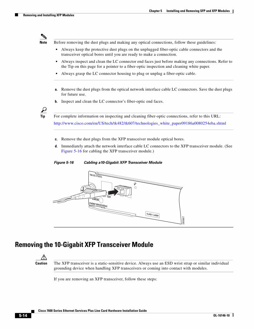
d. Immediately attach the network interface cable LC connectors to the XFP transceiver module. (See Figure 5-16 for cabling the XFP transceiver module.)
Figure 5-16 Cabling a10-Gigabit XFP Transceiver Module
Removing the 10-Gigabit XFP Transceiver Module
Caution The XFP transceiver is a static-sensitive device. Always use an ESD wrist strap or similar individual grounding device when handling XFP transceivers or coming into contact with modules.
If you are removing an XFP transceiver, follow these steps:
7600-ES+ 2TG3CXL
ETHERNET SERVICES MODULE
STATUS
EXT CLK
CLASS 1 LASER
A/L
1
2808
67
5-14Cisco 7600 Series Ethernet Services Plus Line Card Hardware Installation Guide
OL-16146-10

Chapter 5 Installing and Removing SFP and XFP Modules Removing and Installing XFP Modules
Step 1 Disconnect the network interface cable from the XFP transceiver connectors. Immediately reinstall the dust plug in the fiber-optic cable LC connector.
Step 2 Pivot the XFP transceiver bale clasp up to release the XFP transceiver from the socket. (See Figure 5-17.)
Step 3 Slide the XFP transceiver out of the socket. Pivot the bale clasp down and immediately install the dust plug in the XFP transceiver optical bores. (See Figure 5-17.)
Step 4 Immediately place the XFP transceiver in an antistatic bag.
Figure 5-17 Removing the 10-Gigabit XFP Transceiver
7600-ES+ 2TG3CXL
ETHERNET SERVICES MODULE
STATUS
EXT CLK
CLASS 1 LASER
A/L
1
7600-ES+ 2TG3CXL
ETHERNET SERVICES MODULE
STATUS
EXT CLK
CLASS 1 LASER
A/L
1
2808
68
5-15Cisco 7600 Series Ethernet Services Plus Line Card Hardware Installation Guide
OL-16146-10
Chapter 5 Installing and Removing SFP and XFP Modules Removing and Installing XFP Modules
5-16Cisco 7600 Series Ethernet Services Plus Line Card Hardware Installation Guide
OL-16146-10