INSTALLER REFERENCE Jet COMPANY: STAMP … MANUAL Gear motor for swing gates EN MADE IN ITALY...
16
INSTRUCTION MANUAL Gear motor for swing gates MADE IN ITALY EN Jet
Transcript of INSTALLER REFERENCE Jet COMPANY: STAMP … MANUAL Gear motor for swing gates EN MADE IN ITALY...
INSTRUCTION MANUAL
Gear motor for swing gates
MADE IN ITALY EN
STAMPCOMPANY:
PLACE:
PROVINCE:
TELEPHONE NUMBER:
CONTACT PERSON:
INSTALLER REFERENCE
PRODUCER REFERENCE
Jet
King Gates S.r.l.Via A. Malignani, 42 - 33077 Sacile (PN) ITALYTel. +39 0434 737082 - Fax +39 0434 786031e-mail: [email protected] web: www.king-gates.com

1A - WARNINGS
1B - AVAILABLE VERSIONS
1 - GENERAL DESCRIPTION
Unfulfilment of the below listed instructions will release the KING gates srl, from any responsibility for damage caused to people or things.-Do not modify the product in any part.-To optimize the functioning of the automation use KING gates accessories only.-Installing, testing and first functioning have to observe the laws in force.-The gear-motor doesn’t require any maintenance because provided with a permament lubrification system.-Disposal of waste material has to observe local regulations.
A - Gear-motorB - Control unit
C - Flashing-light with antennaD - Photocells (while closing)
E - Photocells (while opening)F - Key selector
G - Warning signH - Stop locks
2A - TYPICAL SYSTEM
C
G
A
H
B
AH
E2H
E1
D2
F
D1
F C
0,5mm2 (dist max 20m) 0,5mm2 (dist max 20m)
0,5mm2 (dist max 50m) 0,5mm2 (dist max 50m)
Ant + -
E2 E1 Tx Rx
+ + NC - PHO2 - -
B
A
2B - TYPICAL CONNECTION AND CABLE SECTION
2 - TYPICAL SYSTEM
RG58 (dist max 5m)
0,5mm2 (dist max 30m) 0,5mm2 (dist max 30m) 0,5mm2 (dist max 30m)
D2 D1 Tx Rx
+ + NC - PHO2 - - 0,5mm2 (dist max 30m) 0,5mm2 (dist max 30m) 0,5mm2 (dist max 30m)
L
N
1,5mm2 (dist max 20m) 1,5mm2 (dist max 20m)
A min 3X0,75
min 3X0,75
AVAILABLE VERSIONS
Code Motor Mechanical stop Fixing kit Protective brushes
Wing maxdimensions
Jet 230 F 230 Vac 3 m; 600 kgJet 230 S 230 Vac 3 m; 600 kgJet 24 24 Vdc 3 m; 600 kgJet 230 F TOP 230 Vac 3 m; 600 kgJet 230 S TOP 230 Vac 3 m; 600 kgJet 24 TOP 24 Vdc 3 m; 600 kg
JET – TECHNICAL DATACodePower supply V 230Motor power supply V 230 24Motor power 200 50SpeedJourneyProtection level 44Motor weight 8Max length of the gate 3Max weight of the gate 600Work cycle
Motor dimensions
30 90
Working temperature

2C - DIMENSIONS
820
100
110
OPENINGANGLE
130mm
40mm
130mm
130mm
60mm
60mm
Frontbraket
Rearbraket
Rear verticalbraket
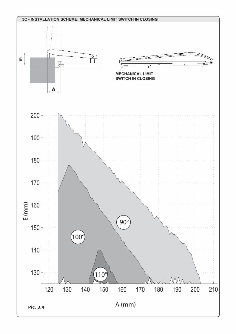
3A - HOW TO USE THE SCHEME
Measure "E" and draw a horizontal line in the scheme (pic.3.3 or 3.4 or 3.5 or 3.6) at the corresponding value. Choose a point on the drawn line, considering the desired opening angle.Draw a vertical line from that point and determinate the A value. Verify that the A value allows the fixing of the rear bracket before continuing the installation, otherwise choose another point on the scheme.
Finally, bring the piston to the limit position (see picture 3.2).Pay attention: avoid that the sliding pivot touches the aluminium cover.
If the installation measures are not properly followed, the automation may not workcorrectly. For example:- Cyclical trends, and sudden accelerations- Noise of the motor- Limited opening degree or absent opening (in case of motor counter-lever configuration)
A
E
3 - BRACKETS INSTALLATION SCHEME
Pic. 3.1
Pic. 3.2

2C - DIMENSIONS
820
100
110
OPENINGANGLE
130mm
40mm
130mm
130mm
60mm
60mm
Frontbraket
Rearbraket
Rear verticalbraket
3A - HOW TO USE THE SCHEME
Measure "E" and draw a horizontal line in the scheme (pic.3.3 or 3.4 or 3.5 or 3.6) at the corresponding value. Choose a point on the drawn line, considering the desired opening angle.Draw a vertical line from that point and determinate the A value. Verify that the A value allows the fixing of the rear bracket before continuing the installation, otherwise choose another point on the scheme.
Finally, bring the piston to the limit position (see picture 3.2).Pay attention: avoid that the sliding pivot touches the aluminium cover.
If the installation measures are not properly followed, the automation may not workcorrectly. For example:- Cyclical trends, and sudden accelerations- Noise of the motor- Limited opening degree or absent opening (in case of motor counter-lever configuration)
A
E
3 - BRACKETS INSTALLATION SCHEME
Pic. 3.1
Pic. 3.2
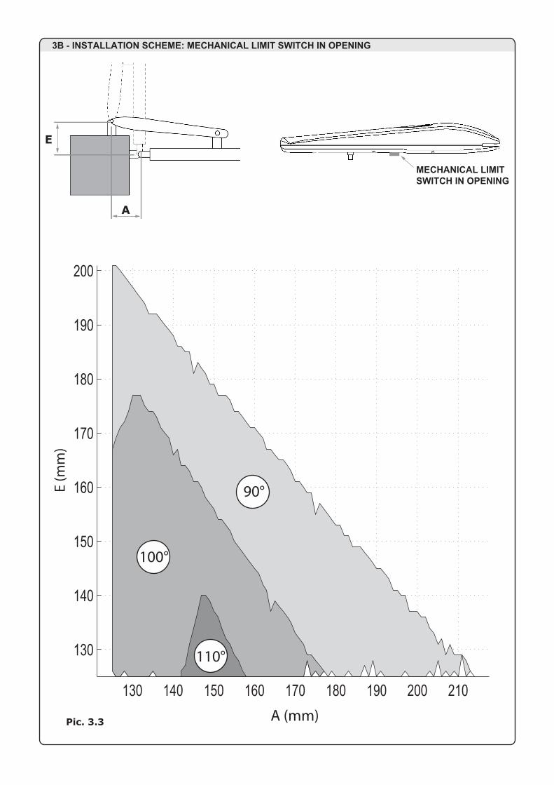
3B - INSTALLATION SCHEME: MECHANICAL LIMIT SWITCH IN OPENING
A (mm)
E (m
m)
130 140 150 160 170 180 190 200 210
130
140
150
160
170
180
190
200
A
MECHANICAL LIMITSWITCH IN OPENING
Pic. 3.3
E
3C - INSTALLATION SCHEME: MECHANICAL LIMIT SWITCH IN CLOSING
A (mm)
E (m
m)
A
MECHANICAL LIMITSWITCH IN CLOSING
Pic. 3.4
E
110°
120 130 140 150 160 170 180 190 200 210
130
140
150
160
170
180
190
200
110°
90°
100°
90°
100°

3D - INSTALLATION SCHEME: MECHANICAL STOPS (IN OPENING AND CLOSING, JET TOP VERSION)
A (mm)
E (m
m)
A
OPENINGMECHANICALSTOP
Pic. 3.5
E
3E - INSTALLATION SCHEME: NO MECHANICAL STOPS
A (mm)
E (m
m)
A
NO MECHANICAL STOPS
Pic. 3.4
E
CLOSINGMECHANICALSTOP
130 140 150 160 170 180
130
135
140
145
150
155
160
165
170
90°
100°
120 140 160 180 200 220
130
140
150
160
170
180
190
200
210
220
110°
90°
100°
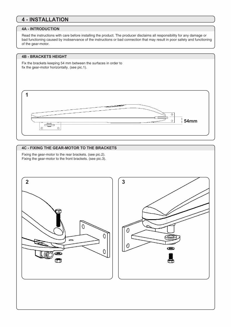
4A - INTRODUCTIONRead the instructions with care before installing the product. The producer disclaims all responsibility for any damage or bad functioning caused by inobservance of the instructions or bad connection that may result in poor safety and functioning of the gear-motor.
4B - BRACKETS HEIGHTFix the brackets keeping 54 mm between the surfaces in order tofix the gear-motor horizontally. (see pic.1).
4 - INSTALLATION
54mm
1
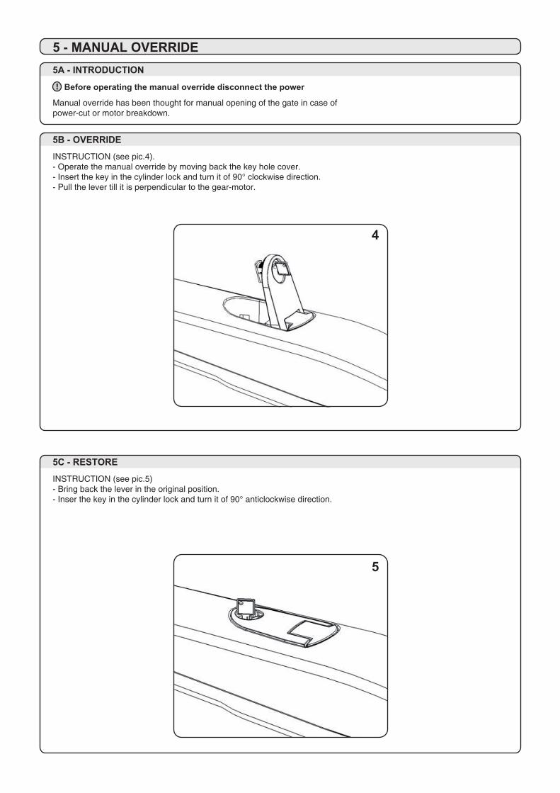
Before operating the manual override disconnect the power!
5A - INTRODUCTION
Manual override has been thought for manual opening of the gate in case ofpower-cut or motor breakdown.
5B - OVERRIDE
INSTRUCTION (see pic.4).- Operate the manual override by moving back the key hole cover.- Insert the key in the cylinder lock and turn it of 90° clockwise direction.- Pull the lever till it is perpendicular to the gear-motor.
5C - RESTORE
INSTRUCTION (see pic.5)- Bring back the lever in the original position.- Inser the key in the cylinder lock and turn it of 90° anticlockwise direction.
5 - MANUAL OVERRIDE
4C - FIXING THE GEAR-MOTOR TO THE BRACKETSFixing the gear-motor to the rear brackets. (see pic.2).Fixing the gear-motor to the front brackets. (see pic.3).
2 3
4
5
4A - INTRODUCTIONRead the instructions with care before installing the product. The producer disclaims all responsibility for any damage or bad functioning caused by inobservance of the instructions or bad connection that may result in poor safety and functioning of the gear-motor.
4B - BRACKETS HEIGHTFix the brackets keeping 54 mm between the surfaces in order tofix the gear-motor horizontally. (see pic.1).
4 - INSTALLATION
54mm
1
Before operating the manual override disconnect the power!
5A - INTRODUCTION
Manual override has been thought for manual opening of the gate in case ofpower-cut or motor breakdown.
5B - OVERRIDE
INSTRUCTION (see pic.4).- Operate the manual override by moving back the key hole cover.- Insert the key in the cylinder lock and turn it of 90° clockwise direction.- Pull the lever till it is perpendicular to the gear-motor.
5C - RESTORE
INSTRUCTION (see pic.5)- Bring back the lever in the original position.- Inser the key in the cylinder lock and turn it of 90° anticlockwise direction.
5 - MANUAL OVERRIDE
4C - FIXING THE GEAR-MOTOR TO THE BRACKETSFixing the gear-motor to the rear brackets. (see pic.2).Fixing the gear-motor to the front brackets. (see pic.3).
2 3
4
5

6A - CONNECTION TO THE POWER STATIONThe installer is provided with the assembled connector.This has the function of connecting the motor to the power station and to power it. This procedure can only be carried out by authorized staff.Dismantle the connector by unscrewing screw “A” (see pic.6)
ATTENTION: the electrical connection within the gear-motor is already provided.
6 - ELECTRICAL CONNECTION
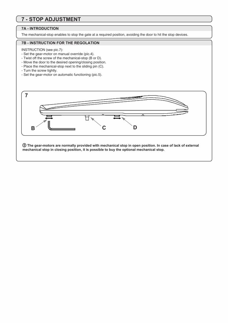
The gear-motors are normally provided with mechanical stop in open position. In case of lack of externalmechanical stop in closing position, it is possible to buy the optional mechanical stop.!
7A - INTRODUCTIONThe mechanical-stop enables to stop the gate at a required position, avoiding the door to hit the stop devices.
7B - INSTRUCTION FOR THE REGOLATION
INSTRUCTION (see pic.7):- Set the gear-motor on manual override (pic.4).- Twist off the screw of the mechanical-stop (B or D).- Move the door to the desired opening/closing position.- Place the mechanical-stop next to the sliding pin (C).- Turn the screw tightly.- Set the gear-motor on automatic functioning (pic.5).
7 - STOP ADJUSTMENT
7
B
6
C DA
6A - CONNECTION TO THE POWER STATION
JET 230 FJET 230 SJET 230 F TOPJET 230 S TOP
1 Phase 12 Phase 23 Common Ground
123
JET 24JET 24 TOP
1 M+2 M-3 Not used Ground
123
6A - CONNECTION TO THE POWER STATIONThe installer is provided with the assembled connector.This has the function of connecting the motor to the power station and to power it. This procedure can only be carried out by authorized staff.Dismantle the connector by unscrewing screw “A” (see pic.6)
ATTENTION: the electrical connection within the gear-motor is already provided.
6 - ELECTRICAL CONNECTION
The gear-motors are normally provided with mechanical stop in open position. In case of lack of externalmechanical stop in closing position, it is possible to buy the optional mechanical stop.!
7A - INTRODUCTIONThe mechanical-stop enables to stop the gate at a required position, avoiding the door to hit the stop devices.
7B - INSTRUCTION FOR THE REGOLATION
INSTRUCTION (see pic.7):- Set the gear-motor on manual override (pic.4).- Twist off the screw of the mechanical-stop (B or D).- Move the door to the desired opening/closing position.- Place the mechanical-stop next to the sliding pin (C).- Turn the screw tightly.- Set the gear-motor on automatic functioning (pic.5).
7 - STOP ADJUSTMENT
7
B
6
C DA
6A - CONNECTION TO THE POWER STATION
JET 230 FJET 230 SJET 230 F TOPJET 230 S TOP
1 Phase 12 Phase 23 Common Ground
123
JET 24JET 24 TOP
1 M+2 M-3 Not used Ground
123

DICHIARAZIONE CE DI CONFORMITÀDECLARATION OF CONFORMITY NOTES
Il sottoscritto Alex Antoniolli, legale rappresentante della ditta King gates srl, dichiara che il prodotto:The undersigned Alex Antoniolli, general manager of the following producer,declares that the product:
NOME PRODUTTORE: King gates srlManufacturer’s name:
INDIRIZZO: Via A. Malignani 42, 33077 Sacile (PN) ItalyAddress:
TIPO: Attuatore elettromeccanico per cancelli a battentiType: Electromechanical gearmotor for swing gates
MODELLO: Jet 230 F, Jet 230 S, Jet 24 Model: Jet 230 F Top, Jet 230 S Top, Jet 24 Top
Risulta conforme a quanto previsto dalle seguenti direttive europee:Satisfies the essential requirements of the following Directives:
DIRETTIVA BASSA TENSIONELow Voltage Directive2006/95/CEEN60335-1EN60335-2-103
DIRETTIVA MACCHINEMachinery Directive2006/42/CE
COMPATIBILITÀ ELETTROMAGNETICA Electromagnetic Compatibility2004/108/EC, 92/31/EEC, 93/68/EEC, 91/263/EECEN61000-6-1EN61000-6-3
Come previsto dalla direttiva 2006/42/CE si avverte che non è consentita la messa in servizio del prodotto sopra indicato finché la macchina, in cui ilprodotto è incorporato, non sia stata identificata e dichiarata conforme alla direttiva 2006/42/CE.As specified in the directive 2006/42/CE use of the product specified above is not admitted until the machine on which it is mounted has been identified and declared asconforming to the directive 2006/42/CE.
Sacile, 05 Settembre 2011 Il legale rappresentatnteSacile, 05 September 2011 Managing Director Alex Antoniolli

INSTRUCTION MANUAL
Motor gear for swing gates
MADE IN ITALY EN
STAMPCOMPANY:
PLACE:
PROVINCE:
TELEPHONE NUMBER:
CONTACT PERSON:
INSTALLER REFERENCE
PRODUCER REFERENCE
Jet
King Gates S.r.l.Via A. Malignani, 42 - 33077 Sacile (PN) ITALYTel. +39 0434 737082 - Fax +39 0434 786031e-mail: [email protected] web: www.king-gates.com