
Installation/User Manual Important Safety Notice - · PDF fileLancer Evolution VIII/VII Super...
13
Lancer Evolution VIII/VII Super Traction Rear LSD Kit RA534828K1 Installation/User Manual Thank you for purchasing our Ralliart product. This installation/user manual explains the procedure for installing this product as well as information on how to use it effectively. Please read this manual carefully to ensure thorough understanding of the details of this product before installation. Give this manual to the customer to save for future reference. Please follow the instructions in this manual carefully to ensure proper installation of this product. • This manual contains the following warning symbols: This indicates important safety information that must be carefully observed. All safety messages that follow this symbol must be carefully observed in order to reduce the risk of personal injury or accidents. This indicates information that should be observed when installing parts. • Install the parts to the car as instructed in this manual. Failure to follow the instructions may hamper the function of this product or cause car trouble. • Be aware that Ralliart takes no responsibility for any product malfunction or car trouble that occurs during or after installation of this product. CAUTION NOTICE CAUTION Important Safety Notice After installing this product, please give the customer this installation/user manual to save for future reference.
Transcript of Installation/User Manual Important Safety Notice - · PDF fileLancer Evolution VIII/VII Super...
Lancer Evolution VIII/VII
Super Traction Rear LSD Kit RA534828K1
Installation/User Manual Thank you for purchasing our Ralliart product. This installation/user manual explains the procedure for installing this product as well as information on how to use it effectively. Please read this manual carefully to ensure thorough understanding of the details of this product before installation. Give this manual to the customer to save for future reference.
Please follow the instructions in this manual carefully to ensure proper installation of this product. • This manual contains the following warning symbols:
This indicates important safety information that must be carefully observed.
All safety messages that follow this symbol must be carefully observed in order to reduce the risk of personal injury or accidents. This indicates information that should be observed when installing parts.
• Install the parts to the car as instructed in this manual. Failure to follow the instructions
may hamper the function of this product or cause car trouble. • Be aware that Ralliart takes no responsibility for any product malfunction or car trouble that
occurs during or after installation of this product.
CAUTION
NOTICE
CAUTION
Important Safety Notice
After installing this product, please give the customer this installation/user manual to save for future reference.
CT9-202-0302 1
To the Owner
Precautions for Use 1. Do not use or install this product on non-applicable car models. Such installation could result in car
damage or accidents. 2. Do not modify or disassemble this product in any manner. 3. Because this product is a mechanical (multi-plate type) LSD assembly, it may cause a dragging noise
from the drive wheels or a rattling noise (chatter) from the differential gears during cornering maneuvers. 4. If you experience any problems when driving your car after this product is installed, stop your car
immediately and have it checked at a repair shop. Failure to do so could result in car damage or accidents.
5. Install this product using only the specified parts supplied in the kit. Do not combine parts of other products into the assembly of this product.
6. Have your car inspected when necessary to maintain normal installation and operating conditions of this product.
7. If the original function of this product cannot be maintained due to damage or deterioration, replace it immediately.
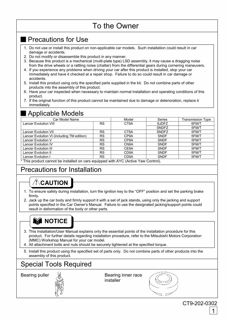
Applicable Models Car Model Name Model Series Transmission Type
SJDFZ 6FM/T Lancer Evolution VIII RS CT9A SNDFZ 5FM/T
Lancer Evolution VII RS CT9A SNDFZ 5FM/T Lancer Evolution VI (including TM edition) RS CP9A SNDF 5FM/T Lancer Evolution V RS CP9A SNDF 5FM/T Lancer Evolution IV RS CN9A SNDF 5FM/T Lancer Evolution III RS CE9A SNDF 5FM/T Lancer Evolution II RS CD9A SNDF 5FM/T Lancer Evolution I RS CD9A SNDF 5FM/T
* This product cannot be installed on cars equipped with AYC (Active Yaw Control).
Precautions for Installation
1. To ensure safety during installation, turn the ignition key to the “OFF” position and set the parking brake firmly.
2. Jack up the car body and firmly support it with a set of jack stands, using only the jacking and support points specified in the Car Owner’s Manual. Failure to use the designated jacking/support points could result in deformation of the body or other parts.
3. This Installation/User Manual explains only the essential points of the installation procedure for this
product. For further details regarding installation procedure, refer to the Mitsubishi Motors Corporation (MMC) Workshop Manual for your car model.
4. All attachment bolts and nuts should be securely tightened at the specified torque. 5. Install this product using the specified set of parts only. Do not combine parts of other products into the
assembly of this product.
Special Tools Required
CAUTION
NOTICE
Bearing puller Bearing inner race installer

CT9-202-0302 2
Kit Contents (Ensure that the following parts are contained in the kit.) Rear LSD
Other Parts Required (The following parts must be purchased separately for installation of this product)
Two MB393957 side bearings 1 set of MB241903 spacers
CT9-202-0302 3
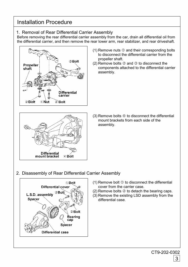
Installation Procedure 1. Removal of Rear Differential Carrier Assembly Before removing the rear differential carrier assembly from the car, drain all differential oil from the differential carrier, and then remove the rear lower arm, rear stabilizer, and rear driveshaft.
(1) Remove nuts and their corresponding bolts to disconnect the differential carrier from the propeller shaft.
(2) Remove bolts and to disconnect the components attached to the differential carrier assembly.
(3) Remove bolts to disconnect the differential
mount brackets from each side of the assembly.
2. Disassembly of Rear Differential Carrier Assembly
(1) Remove bolt to disconnect the differential cover from the carrier case.
(2) Remove bolts to detach the bearing caps. (3) Remove the existing LSD assembly from the
differential case.
CT9-202-0302 4
Installation Procedure
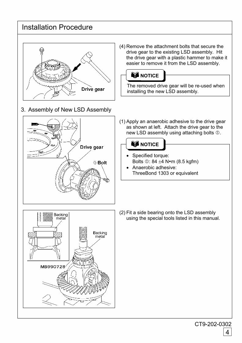
(4) Remove the attachment bolts that secure the
drive gear to the existing LSD assembly. Hit the drive gear with a plastic hammer to make it easier to remove it from the LSD assembly.
The removed drive gear will be re-used when installing the new LSD assembly.
3. Assembly of New LSD Assembly
(1) Apply an anaerobic adhesive to the drive gear
as shown at left. Attach the drive gear to the new LSD assembly using attaching bolts .
• Specified torque: Bolts : 84 ±4 N m (8.5 kgfm)
• Anaerobic adhesive: ThreeBond 1303 or equivalent
(2) Fit a side bearing onto the LSD assembly
using the special tools listed in this manual.
NOTICE
NOTICE

CT9-202-0302 5
Installation Procedure
4. Assembly of Rear Differential Carrier Assembly (1) Attach a side bearing outer race to the LSD
assembly and also attach spacers that have been selected according to the backlash adjustment procedure specified in the MMC Workshop Manual. Install the LSD assembly on the carrier case.
(2) Align the alignment marks of the carrier case with those of each bearing cap, and secure the bearing caps to the carrier case by means of bolts .
(3) Apply a semi-drying sealing agent over the mating surface of the differential cover, and attach it to the carrier case using bolts .
• Specified torque: Bolts : 37 ±2 N m (3.8 kgfm) Bolts : 36 ±5 N m (3.7 kgfm)
• Semi-drying sealing agent: ThreeBond 1216 or equivalent
5. Installation of Rear Differential Carrier Assembly
(1) Install the rear differential carrier assembly on the car in the reverse order of the removal procedure.
• Specified torque: Bolts : 88 ±10 N m (9.0 kgfm) Bolts : 120 ±10 N m (12.2 kgfm) Bolts : 88 ±10 N m (9.0 kgfm) Nuts : 32 ±2 N m (3.2 kgfm)
NOTICE
NOTICE

CT9-202-0302 6
Installation Procedure
(2) Fill the specified differential oil into the differential case so that the fluid level reaches the bottom of the opening for the filler plug, then attach and tighten the filler plug at the specified torque.
• Specified differential oil: Mitsubishi Genuine Dia Queen LSD Gear Oil (GL-5)
• Specified torque: Filler plug: 49 ±9 N m (5.0 kgfm)
Reference Information Scheduled Interval for Fluid Change After Installation
Periodic replacement item
Replacement interval Capacity (dm3) Product Name
Differential oil 20,000 km 0.55 Mitsubishi Genuine Dia Queen LSD Gear Oil (GL-5)
The above fluid change interval is a guideline only. The differential oil may deteriorate more quickly depending on its conditions of use. In such cases, it is recommended to replace the oil sooner than the above recommended interval.
NOTICE
NOTES
NOTICE

Overhaul Manual Thank you for purchasing our product. This overhaul manual explains the procedure for overhauling the super traction rear L.S.D. assembly installed on Lancer Evolution VIII/VII. Please read this manual carefully to ensure thorough understanding of the details of this product before overhaul. Give this manual to the customer to save for future reference.
Please follow the instructions in this manual carefully to ensure proper installation of this product.
• This manual contains the following warning symbols.
This indicates important safety information. All safety messages that follow this symbol must be carefully observed in order to reduce the risk of personal injury or accidents. This indicates information that must be observed when installing parts.
• Install the parts to the vehicle as instructed in this manual. Failure to follow the instructions
may hamper the function of the product or cause vehicle trouble. • Be aware that RALLIART takes no responsibility for any product malfunction or vehicle
trouble that has occurred during or after the installation.
CAUTION
NOTICE
CAUTION
Important Safety Notice
On completion of installation of the garnish, please give the customer this installation/user manual

1 1
Instructions
[Components of Rear LSD Assembly] [Assembly of Rear LSD] 1. Assembly procedure and direction of each plate
• Please refer to the above figure for the assembly procedure and direction of the plates in the instructions to be explained hereafter.
NOTICE
No. Product Name QTY Available as spare part Note Case A 1 --- Case B 1 --- Side gear 2 --- Pinion gear 4 --- Pinion shaft 1 --- Friction plate 8 Outer lug Friction disc 8 Inner lug Cam ring set 1 55°/35°-55°/55° Corn spring 2 T=1.7mm (Ti=190N m)
Friction discs Friction discs

2 2
Instructions 2. Assembly of the pinion shaft and the cam rings (1) The cam ring has grooves of angles of 35° (1.8-way) and 55° (2-way) in the coast side.
In the case where the 35° groove (1.8 way) is assembled in the coast side
In the case where the 55° groove (2 way) is assembled in the coast side
(3) After completion of the assembly, the assembly looks like either of the following figures.
View from the case A
Pinion shaft assembled in the 55°/35° groove
View from the case A
Pinion shaft assembled in the 55°/55° groove
(2) Align the pinion shaft and the mating surfaces of the cam rings snugly as shown in the
figure below. Improper alignment could damage the LSD assembly.
• The 35° groove in the coast side is located
where there is a fitting projection in the cam ring.
NOTICE
CAUTION

3 3
Instructions 3. Assembly of the inner plates Measure the depth of the case (A) and the assembly height of the inner plates (D) as shown below, and assemble the inner plates, the case A, and the case B so that the clearance (S) in the assembled case is within the standard values (See the last Note in this page).
(1) Measurement of the depth (A) Measure the depth of the case A and B, and calculate the depth (A) by adding the two measured values, (a) and (b); (A) = (a) + (b)
(2) Measurement of the assembled height (D) of the inner plates Assemble the plates, cam rings, pinion shaft, pinion gears, and side gears, and measure the height (D) with a micrometer.
(3) Measurement of the clearance
Calculate the clearance (S) from the depth (A) and the height of the inner plates (D). (S) = (A) – (D)
• Clearance (S) Standard value: 0.06 to 0.25 mm
• Measure while pressing from both sides so that each plate contacts with each other.
• Clean every part sufficiently prior to measurement.
• Ensure that the pinion shaft is properly placed between two cam rings so that each corresponding groove faces each other.
• Measure the depth excluding the depth of
the hollow part for setting the corn spring.
NOTICE
NOTICE
NOTICE

4 4
Instructions (4) Adjustment of clearance
Where the clearance is out of the standard values, replace the friction plates with those of proper thickness so that the assembly height of the inner plates is within the range of the standard values.
5. Cam angle and initial torque at delivery
Cam angle Initial torque 55°/55°
(Drive side/coast side) approx. 190N m
∗ The initial torque is a value set at the
installation in the vehicle. A half of the initial torque is to be measured in the procedure shown in the figure at left.
• Thickness of the alternative friction plates RA282104K1: 1.6 mm RA138432K1: 1.7 mm RA163449K1: 1.8 mm
NOTICE

5 5
Instructions [Spare parts]
No. Part Name Part Number Price (yen) Remarks RA282104K1 2200/piece Outer lug (T=1.6 mm) RA138432K1 2200/piece Outer lug (T=1.7 mm) Friction plate RA163449K1 2200/piece Outer lug (T=1.8 mm)
Friction disc RA138433K1 2200/piece Inner lug (T=1.7 mm)
Cam ring set (Right and left per set) RA192402S1 23000/set 55°/55°-55°/35°
RA792400K1 2900/piece T=1.7 mm (Ti=190 N m) Corn spring RA783801K1 2900/piece T=2.0 mm (Ti=255 N m)


![[LSD]Remembrances of LSD Therapy Past-Betty Grover Eisner, org](https://static.fdocuments.us/doc/165x107/577dab601a28ab223f8c57f0/lsdremembrances-of-lsd-therapy-past-betty-grover-eisner-org.jpg)

