Installation/Service Manual Economy Oven
25
Installation/Service Manual Economy Oven Models 14EG (6520/6521), 25EG (6522/6523), 45EG (6524/6525), 25EM (6526/6527), 45EM (6528/6529) Thermo Electron Corporation Millcreek Road, Box 649 Marietta, Ohio 45750 USA Phone: 740-373-4763 Toll Free: 800-848-3080 FAX: 740-373-4189 Manual P/N 3177886 Rev E Dated 11AUG05
Transcript of Installation/Service Manual Economy Oven

Installation/Service ManualEconomy Oven
Models 14EG (6520/6521), 25EG (6522/6523), 45EG (6524/6525),25EM (6526/6527), 45EM (6528/6529)
Thermo Electron CorporationMillcreek Road, Box 649Marietta, Ohio 45750USAPhone: 740-373-4763Toll Free: 800-848-3080FAX: 740-373-4189
Manual P/N 3177886Rev E Dated 11AUG05

NOTICE
THE MATERIAL IN THIS MANUAL IS FOR INFORMATION PURPOSES ONLY. THECONTENTS AND THE PRODUCT IT DESCRIBES ARE SUBJECT TO CHANGE WITHOUTNOTICE. THERMO ELECTRON CORPORATION MAKES NO REPRESENTATIONS ORWARRANTIES WITH RESPECT TO THIS MANUAL. IN NO EVENT SHALL THERMO BELIABLE FOR ANY DAMAGES, DIRECT OR INCIDENTAL, ARISING OUT OF OR RELATED TOTHE USE OF THIS MANUAL.
For repair information or replacement parts assistance from the manufacturer,call Technical Services using our toll free telephone number.
888-213-1790(FAX) 740-373-4189
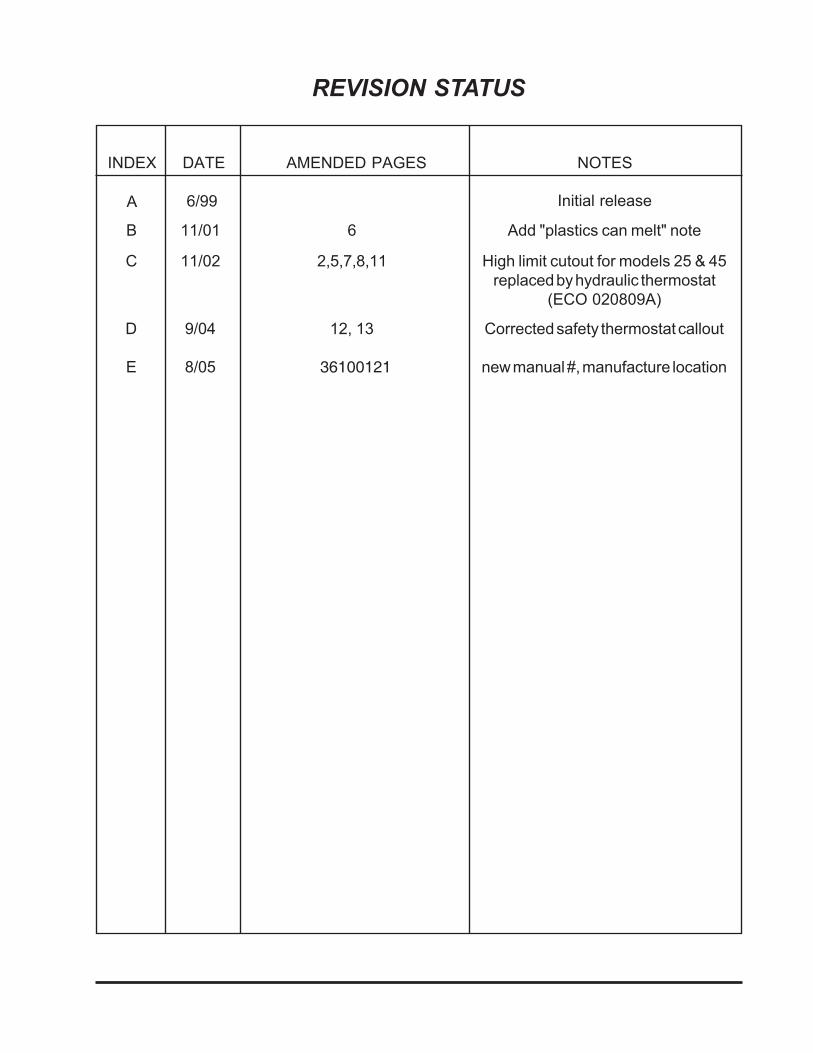
Initial releaseA
INDEX DATE AMENDED PAGES NOTES
REVISION STATUS
6/99
B 11/01 6 Add "plastics can melt" note
C 11/02 2,5,7,8,11 High limit cutout for models 25 & 45replaced by hydraulic thermostat
(ECO 020809A)
D
E
9/04
8/05
12, 13
36100121
Corrected safety thermostat callout
new manual #, manufacture location

Contents1. INTRODUCTION .............................................................................................................. 1
2. UNPACKING AND DAMAGE .......................................................................................... 1
3. GENERAL INFORMATION.............................................................................................. 2
4. SPECIFICATIONS ........................................................................................................... 3
5. INSTALLATION ............................................................................................................... 4
6. EXPLANATION OF CONTROLS..................................................................................... 4
7. OPERATION .................................................................................................................... 5
8. MAINTENANCE & SERVICING ...................................................................................... 7
9. PARTS REPLACEMENT ................................................................................................ 8
10. ELECTRICAL DRAWINGS ......................................................................................... 11
11. REPLACEMENT PARTS LIST .................................................................................... 13
12. WARRANTY................................................................................................................. 14

Warnings and Notices
Important: READ THESE NOTICES BEFORE INSTALLING THE UNIT
General Notices
AS A ROUTINE LABORATORY PRECAUTION, ALWAYS WEAR SAFETY GLASSES WHENWORKING WITH THIS APPARATUS.
INSTALLATION SHOULD BE COMPLETED BY QUALIFIED PERSONNEL ONLY.
WITHIN THE MECHANICAL CONVECTION CABINETS, OBJECTS SHOULD NOT BEPLACED ON THE SHELVES IN SUCH A MANNER TO BLOCK THE MOVEMENT OFHEATED AIR INTO THE CHAMBER.
Electrical Warnings
FOR PERSONAL SAFETY, THIS APPARATUS MUST BE PROPERLY GROUNDED.
BE SURE THAT THE POWER SUPPLY IS OF THE SAME VOLTAGE AS SPECIFIED ONTHE NAMEPLATE.
DANGEROUS VOLTAGES EXIST WITHIN THIS UNIT. SERVICE SHOULD BE PERFORMEDONLY BY QUALIFIED PERSONNEL. DISCONNECT THE UNIT FROM ITS ELECTRICALSOURCE. REMOVE THE SHELVES AND THERMOMETER IF INSTALLED.DISCONNECTING ANY COMPONENT FROM THE CIRCUIT WITHOUT PRIOR REMOVALOF THE POWER SOURCE MAY CAUSE DAMAGE TO OTHER CIRCUIT COMPONENTS.
DO NOT CRIMP OR SHARPLY BEND CAPILLARIES. PROVIDE ADEQUATE CLEARANCEBETWEEN CAPILLARY AND HEATER COILS TO PREVENT ELECTRICAL SHORT.
DISCONNECT OVEN FROM ITS POWER SOURCE BEFORE SERVICING.

1
1. INTRODUCTION
1.01 Your satisfaction and safety areimportant to Thermo and a completeunderstanding of this unit is necessary to attainthese objectives.
1.02 As the user of this apparatus, you havethe responsibility to understand the properfunction and operational characteristics of it.This instruction manual should be thoroughlyread and all operators given adequate trainingbefore attempting to place this unit in service.Awareness of the stated cautions and warnings,and compliance with recommended operatingparameters -- together with maintenancerequirements -- are important for safe andsatisfactory operation. The unit should be usedfor its intended application; alterations ormodifications will VOID THE WARRANTY.
WARNINGAS A ROUTINE LABORATORY PRECAUTION,ALWAYS WEAR SAFETY GLASSES WHENWORKING WITH THIS APPARATUS.
1.03 This product is not intended, nor can itbe used, as a sterile or patient connecteddevice. In addition, this apparatus is notdesigned for use in Class I, II or III locations asdefined by the National Electrical Code.
2. UNPACKING AND DAMAGE
2.01 Save all packing material if apparatus isreceived damaged. This merchandise wascarefully packed and thoroughly inspectedbefore leaving our factory.
2.02 Responsibility for safe delivery wasassumed by the carrier upon acceptance of theshipment; therefore, claims for loss or damagesustained in transit must be made upon thecarrier by the recipient as follows:
1. Visible Loss or Damage: Note any externalevidence of loss or damage on the freightbill, or express receipt, and have it signedby the carrier's agent. Failure to adequatelydescribe such external evidence of loss ordamage may result in the carrier's refusingto honor your damaged claim. The formrequired to file such claim will be suppliedby the carrier.
2. Concealed Loss or Damage: Concealedloss or damage means loss or damagewhich does not become apparent until themerchandise has been unpacked andinspected. Should either occur, make awritten request for inspection by carrier'sagent within fifteen (15) days of the deliverydate; then file a claim with the carrier sincethe damage is the carrier's responsibility.
2.03 If you follow the above instructionscarefully, we will guarantee our full support ofyour claim to be compensated for loss orconcealed damage.
DO NOT -- FOR ANY REASON -- RETURNTHIS UNIT WITHOUT FIRST OBTAININGAUTHORIZATION. In any correspondence toThermo, please supply the nameplate data,including catalog number and serial number.


2
3. GENERAL INFORMATION
3.01 This instruction manual encompassesthe following models and their specific electricalcharacteristics.
3.02 Models 14EG, 25EG and 45EG employgravity convection as a method of heat transfer.Gravity convection is defined as the naturaltendency for heated air to rise due to it's changein density and mass.
3.02.1 Air is drawn into the chamber throughopenings in the bottom of the oven and thenheated as it passes over the electric heatingcoils and up through the openings in the diffuserpanel located on the bottom of the inner chamber.A limited amount of heated air is exhausted outof the top of the chamber through the vent shuttercap and the remaining air recirculates within thechamber.
3.02.2 Gravity convection ovens are ideal whereforced air circulation cannot be tolerated and forsituations demanding gentle curing or long termsample storage under closely controlledconditions. Gravity convection ovens are idealfor drying powders, soil samples, paper goods,semiconductors and cosmetics.
3.03 Models 25EM and 45EM use mechanicalconvection as a method of heat transfer.Mechanical convection can be defined as apositive and planned directional air flow or forcedair circulation within the chamber.
3.03.1 Air is drawn into the chamber throughvent tubes located in the bottom of the oven andis heated as it passes over the electric heatingcoils. The air is blown through openings in thebottom of the inner chamber. A limited amountof heated air is exhausted out the top of thechamber through the vent shutter cap and theremaining air recirculates within the chamber.
3.03.2 Mechanical convection ovens providethe most efficient means of heat transfer as wellas the most reproducible test conditions forrepeat operations. Mechanical convectionallows for rapid heat up time for high densityloads, shortened recovery periods after dooropenings and improved uniformity for extremelyheat sensitive samples.
3.04 All models use a hydraulic thermostat fortemperature safety limit control.


3
Economy Ovens
4. Specifications
Model Number 14EG 25EG 25EM 45EG 45EM
ConvectionTechnique Gravity Gravity Mechanical Gravity Mechanical
Temperature Control Hydraulic Electronic Electronic Electronic Electronic
Temperature Display 0° to 250°CThermometer
0° to 250°CThermometer
0° to 250°CThermometer
0° to 250°CThermometer
0° to 250°CThermometer
Temperature Range
Sensitivity65° to 210°C
±0.5°C65° to 210°C
±0.3°C50° to 210°C
±0.3°C65° to 210°C
±0.3°C50° to 210°C
±0.3°C
Dimensions (LxWxH) Chamber
Shelf (each)
Exterior*
14 x 12.5 x 13.75 in. 356 x 318 x 349 mm
13.5 x 12.5 in.343 x 318 mm
19.5 x 18 x 28 in. 495 x 457 x 711 mm
15.5 x 18.5 x 15 in.390 x 470 x 380 mm
15.5 x 18 in.390 x 455 mm
21.5 x 24 x 28 in.550 x 610 x 715 mm
15.5 x 18.5 x 15 in390 x 470 x 380 mm
15.5 x 18 in.390 x 455 mm
21.5 x 24 x 28 in. 550 x 610 x 715 mm
15.5 x 18.5 x 27 in. 390 x 470 x 685 mm
15.5 x 18 in. 390 x 455 mm
21.5 x 24 x 40 in.550 x 610 x 1020 mm
15.5 x 18.5 x 27 in. 390 x 470 x 685 mm
15.5 x 18 in. 390 x 455 mm
21.5 x 24 x 40 in.550 x 610 x 1020 mm
Net Weight 69 lbs., 31 kg 93 lbs., 42.4 kg 103 lbs., 46.7 kg 120 lbs., 54.4 kg 130 lbs.,59 kg
Chamber Volume 1.4 cu.ft.39 liters
2.5 cu.ft.71.5 liters
2.5 cu.ft.71.5 liters
4.5 cu.ft. 129 liters
4.5 cu.ft. 129 liters
Shelves** Supplied Maximum
26
26
26
210
210
Electrical Data***(all models 50/60 Hz)
115V 230V
0.8 kW, 7.1 A0.8 kW, 3.5 A
1.3 kW, 11.3 A1.3 kW, 5.6 A
1.3 kW, 11.3 A1.3 kW, 5.6 A
1.8 kW,15.6 A1.8 kW, 7.8 A
1.8 kW,15.6 A1.8 kW, 7.8 A
Shipping Data Dimensions
(LxWxH)
Weight
Volume
24 x 23 x 30 in. 609 x 584 x 762 mm
79 lbs., 35.5kg
9.8 cu.ft.0.28 cu. meters
25 x 26 x 31.5 in.635 x 660 x 800 mm
117 lbs., 53.1 kg
11.7 cu.ft.0.33 cu. meters
25 x 26 x 31.5 in.635 x 660 x 800 mm
127 lbs., 59.6 kg
11.7 cu.ft.0.33 cu. meters
25 x 26 x 43.5 in.635 x 660 x 1105 mm
145 lbs., 65.8 kg
16.3 cu.ft. 0.46 cu. meters
25 x 26 x 43.5 in.635 x 660 x 1105 mm
155 lbs., 70.3 kg
16.3 cu.ft. 0.46 cu. meters
Catalog Number 115 V 230 V
31667673166768
31667693166770
31667733166774
31667713166772
31667753166776
* Exterior height includes vent cap and adjustable feet** Spacing between shelves is 2 inches (50mm)*** All ovens equipped with line cord and plug


4
5. INSTALLATION
WARNINGINSTALLATION SHOULD BE COMPLETEDBY QUALIFIED PERSONNEL ONLY.
5.01 Location - The most uniform operatingconditions will be obtained by placing the oven inan area remote from drafts, ventilating outlets,radiators, and other rapidly changing ambientconditions. To assure proper ventilation allow aminimum of three (3) inches of clearance betweenthe rear, top and sides of the oven and adjacentwalls. If two or more ovens are to be placed side byside, then allow six (6) inches between them. Thefour legs on the bottom of the oven can be turnedto raise or lower the corners so that it sits level onthe table.
5.02 Electrical Connections -
1. The 14EG, 25EG and 25EM are providedwith a 120V, 15 amp, three-prong (grounding)plug. The 45EG and 45 EM come equipped witha 120V, 20 amp, three-prong (grounding) plug.Both plug configurations are industry standard,and mate with standard three-prong groundingwall receptacles to minimize the possibility ofelectric shock hazard from this apparatus. If indoubt the user should have the wall receptacleand circuit checked by a qualified electrician tomake sure the receptacle can provide adequatecurrent and is properly grounded.
WARNINGFOR PERSONAL SAFETY THIS APPARATUSMUST BE PROPERLY GROUNDED.
2. Where a standard two-prong wallreceptacle is encountered, it is the personalresponsibility and obligation of the user to haveit replaced with a properly grounded three-prongwall receptacle. DO NOT, UNDER ANYCIRCUMSTANCES, CUT OR REMOVE THETHIRD (GROUND) PRONG FROM THEPOWER CORD. DO NOT USE A TWO-PRONG ADAPTER PLUG.
5.03 Determine the total amount of currentbeing used by other apparatus connected to thecircuit that will be used for this apparatus. It iscritical that the added current demand (seenameplate) of this and other equipment used onthe same circuit does not exceed the rating ofthe fuse or circuit breaker.
CAUTIONBE SURE THAT THE POWER SUPPLY ISOF THE SAME VOLTAGE AS SPECIFIEDON THE NAMEPLATE.
6. EXPLANATION OF CONTROLS
6.01 On/Off Switch - The on/off switch controlsthe flow of all electric power to the oven. Theblower motor in the mechanically convectedmodels will always be in operation with thepower switch ON.
6.02 Three-Heat Switch - Model 14EG hasa three heat switch. This switch also functions asthe main "on/off" switch. With this switch it ispossible to supply maximum wattage to the unitfor initial heat-up and then reduce the wattagewhen operating temperature is reached. Lowsetting may be used for temperatures up toapproximately 115°C, medium setting from115°C to 175°C and high setting above 175°C.Most uniform control is achieved when setting isjust high enough to maintain desiredtemperature.
6.03 Temperature Control Knob - TheTemperature Control knob is used to set theoperating temperature. Numerical graduationsdo not refer to any specific temperature but aresimply for reference. As you become familiarwith operating your oven, record dial settingswhich correspond to your preferred operatingtemperatures.
6.04 Temperature Control Pilot Lamp -When the lamp above the Temperature Controlis illuminated, this indicates electric current isbeing applied to the heater. It is normal for thislamp to cycle on and off during the operation ofthe oven.

5
6.05 Safety Control Knob - Model 14EGhas a safety control knob to set the desiredsafety control temperature.
6.06 Safety Cutout Pilot Lamp - When theSafety Cutout Pilot Lamp is illuminated, thisindicates that either the Temperature ControlThermostat or sensor has failed and that theoven is controlling from the Safety Controller.
6.07 Glass Thermometer - Used to indicateoven temperature and determine proper ther-mostat settings.
Safety CutoutPilot Lamp
Temp. ControlPilot Lamp
Power Switch
Temp. ControlKnob
Safety AdjustmentAccess
7. OPERATION
7.01 Fully open the exhaust vent shutter capon the top of the oven and keep it open at alltimes. However, if running the oven at themaximum rated temperature it may be necessaryto turn the cap to a more closed position to retainheat.
Insert shelf supports into the holes punched inthe side walls of the inner chamber. Insert theshelves into the shelf supports and try to keep anequal distance between shelves wheneverpossible. Never cover the shelves with foil orreduce their open surface area by more than75%, this will greatly reduce convection andhence uniformity and control will suffer.
A thermometer is provided and should beinserted through the hole in the vent shutter capsuch that the three metal fingers punched in thecap converge toward the center of the cap andthe glass ring on the thermometer rests on thetop of the cap. The metal fingers may have to bebent slightly to grip the thermometer.
1. Press the ON/OFF switch for power to theON position. For the 14EG only, select thedesired temperature range.
2. Rotate the safety control adjustment fullyclockwise.
3. Rotate the Temperature Control knob tosome median position.
Figure 6.1 - Controls
6
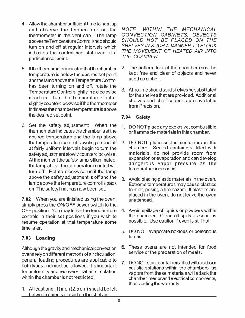
4. Allow the chamber sufficient time to heat upand observe the temperature on thethermometer in the vent cap. The lampabove the Temperature Control knob shouldturn on and off at regular intervals whichindicates the control has stabilized at aparticular set point.
5. If the thermometer indicates that the chambertemperature is below the desired set pointand the lamp above the Temperature Controlhas been turning on and off, rotate theTemperature Control slightly in a clockwisedirection. Turn the Temperature Controlslightly counterclockwise if the thermometerindicates the chamber temperature is abovethe desired set point.
6. Set the safety adjustment: When thethermometer indicates the chamber is at thedesired temperature and the lamp abovethe temperature control is cycling on and offat fairly uniform intervals begin to turn thesafety adjustment slowly counterclockwise.At the moment the safety lamp is illuminated,the lamp above the temperature control willturn off. Rotate clockwise until the lampabove the safety adjustment is off and thelamp above the temperature control is backon. The safety limit has now been set.
7.02 When you are finished using the oven,simply press the ON/OFF power switch to theOFF position. You may leave the temperaturecontrols in their set positions if you wish toresume operation at that temperature sometime later.
7.03 Loading
Although the gravity and mechanical convectionovens rely on different methods of air circulation,general loading procedures are applicable toboth types and must be followed. It is importantfor uniformity and recovery that air circulationwithin the chamber is not restricted.
1. At least one (1) inch (2.5 cm) should be leftbetween objects placed on the shelves.
NOTE: WITHIN THE MECHANICALCONVECTION CABINETS, OBJECTSSHOULD NOT BE PLACED ON THESHELVES IN SUCH A MANNER TO BLOCKTHE MOVEMENT OF HEATED AIR INTOTHE CHAMBER.
2. The bottom floor of the chamber must bekept free and clear of objects and neverused as a shelf.
3. At no time should solid shelves be substitutedfor the shelves that are provided. Additionalshelves and shelf supports are availablefrom Precision.
7.04 Safety
1. DO NOT place any explosive, combustibleor flammable materials in this chamber.
2. DO NOT place sealed containers in thechamber. Sealed containers, filled withmaterials, do not provide room fromexpansion or evaporation and can developdangerous vapor pressure as thetemperature increases.
3. Avoid placing plastic materials in the oven.Extreme temperatures may cause plasticsto melt, posing a fire hazard. If plastics areplaced in the oven, do not leave the ovenunattended.
4. Avoid spillage of liquids or powders withinthe chamber. Clean all spills as soon aspossible. Use caution if oven is still hot.
5. DO NOT evaporate noxious or poisonousfumes.
6. These ovens are not intended for foodservice or the preparation of meals.
7. DO NOT store containers filled with acidic orcaustic solutions within the chambers, asvapors from these materials will attack thechamber interior and electrical components,thus voiding the warranty.


7
8. MAINTENANCE AND SERVICING
8.01 Troubleshooting
WARNINGDANGEROUS VOLTAGES EXIST WITHINTHIS UNIT. SERVICE SHOULD BEPERFORMED ONLY BY QUALIFIEDPERSONNEL. DISCONNECT THE UNITFROM ITS ELECTRICAL SOURCE. REMOVETHE SHELVES AND THERMOMETER IFINSTALLED. DISCONNECTING ANYCOMPONENT FROM THE CIRCUITWITHOUT PRIOR REMOVAL OF THE POWERSOURCE MAY CAUSE DAMAGE TO OTHERCIRCUIT COMPONENTS.
8.02 Temperature Variance or Fluctuation
1. Make sure vent shutter cap is not closed.Open to the maximum position.
2. Test unit when empty; if results aresatisfactory the chamber was improperlyloaded. Redistribute the load.
3. Be sure to allow ample time for an emptychamber to stabilize at the desiredtemperature setting. It could take over onehour to equilibrate depending upon thedifferences between ambient and operatingtemperatures. The mass of the load canalso affect stabilization time.
4. Make certain severe line voltage fluctuationsare not occurring.
5. Make certain all wire connections are secureat their terminals.
6. Make certain that an intermittent failure ofthe switch, thermostat or wiring has notoccurred. Isolate the cause; repair or replace.
8.03 Heat Loss
Inspect door gasket to make certain it fits firmlyagainst cabinet at all points. Replace gasket iftorn or damaged.
Improper Door Closure - Inspect door latcheswhich are spring loaded to see if they pull thedoor in tightly against the body of the oven. If the"finger" of the latch (in the door) has beensprung into the body of the latch, use a pen orsimilar object to pop it back out. Check the ovencabinet to see that it is level. Use a spirit leveland turn the four adjustable feet on the bottom ofthe oven to make it level.
No Heat - If the chamber does not heat, firstcheck the line voltage, circuit breakers and/orfuses of the line circuit. Check if all electricalconnections are secure.


8
9. PARTS REPLACEMENT9.01 Heater Replacement
1. Disconnect power.2. Remove the clamps securing the
thermostat bulbs to the floor. Carefully bendthe bulbs to a vertical position.
3. Remove two screws securing controlpanel and carefully lift control panel andlay it on it's face.Model 14EG: Then remove three screwssecuring the front z-bracket,screws arelocated directly above the control panel.Remove one screw on back wall thatsecures the oven floor. Lift bottom floorstraight up and out to remove it.Model 25 & 45: Remove ten screws thatsecure floor and lift out.
4. Disconnect heater terminals and heatermounting screws. Carefully lift straightup and out.
5. Replace with new heater, reinstall inreverse order.
9.02 Probe Replacement, Models 25 & 45
1. Disconnect power.2. Remove back panel screws.3. Pull probe straight out.4. Open control panel by removing top
screwswhich secure it and disconnect probeterminals.
5. Replace with new probe, reinstall inreverse order.
9.03 Motor Replacement (MechanicalModels only)
1. Disconnect power.2. Open control panel by removing top
screws which secure it and disconnectmotor and heater terminals.
3. Remove screws which secure lowerfloor and lift out.
4. Disconnect/remove heater mountingscrews, remove heater and wires.
5. Detach blower wheel from motor shaft.
8.04 Heater Resistance Check
WARNINGDISCONNECT OVEN FROM ITS POWERSOURCE BEFORE PROCEEDING. REFERTO THE APPROPRIATE WIRING DIAGRAMAT THE END OF THE MANUAL ANDLOCATE THE ELECTRICAL LEADS FORTHE HEATER. USE THE VALUES IN THEHEATER COLD RESISTANCE TABLE TOFIND THE APPROPRIATE VALUE. BE SURETO DISCONNECT AT LEAST ONE HEATERLEAD FROM THE TERMINAL STRIPBEFORE TAKING THE RATING WITH YOUROHM METER. AGAIN, IT IS IMPERATIVETHAT THE UNIT BE COMPLETELYDISCONNECTED FROM ITS ELECTRICALPOWER SOURCE BEFORE ANYREADINGS ARE TAKEN.
If the heater is open (infinite resistance) it shouldbe replaced. If the heater reads less than fiveohms it is shorted and should be replaced.Check the resistance between each lead of theheater and a base metal point on the ovenchassis. If there is less than infinite resistance(a million ohms or greater) between the heaterand chassis, the heater is shorted to the groundand should be replaced. Also, inspect all wiresleading to the heater for signs of shorting orelectrical contact to chassis of oven.

9
6. Turn oven on its back or side and removebottom plate. Remove motor mountingbracket from underside of oven.
7. Replace with new motor, reinstall inreverse order.
9.04 Control Replacement, Models 25 & 451. Disconnect power2. Open control panel by removing top
screws which secure it and disconnectleads to control pcb.
3. Remove control pcb.4. Replace with new control pcb, reinstall
in reverse order.
9.05 Thermostat Replacement:
1. UNPLUG UNIT FROM ELECTRICALSOURCE
2. Loosen thermostat bulbs by removing twoclamps secured to chamber bottom floor.
3. Remove two screws securing control paneland carefully lift control panel and lay iton it's face.
4. Model 14 EG: Remove three screwssecuring the front z-bracket, screws arelocated directly above the control panel.Remove screw securing the oven floor.Lift bottom floor straight up and out, becareful with the thermostat bulbs.Model 25 & 45: Remove ten screws thatsecure floor and lift out. Be careful withthe thermostat bulb.
5. Remove knobs by loosening two setscrews on each knob. (14 EG only)
6. Tag lead wires and detach fromthermostats.
7. Model 14 EG: Remove screws securingthermostat to control panel. Removetwo screws securing angle cover, lo-cated inside of inner chamber on thefront left side. This will give you room topull thermostat bulbs out.Model 25 & 45: Remove thermostatbracket from control panel. Remove ther-mostat from bracket. Remove knob fromthermostat.
8. Pull thermostat bulbs through chamberand out the front.
9. Retrace preceding steps to install thenew thermostat assembly.
CAUTIONDO NOT CRIMP OR SHARPLY BENDCAPILLARIES. PROVIDE ADEQUATECLEARANCE BETWEEN CAPILLARY ANDHEATER COILS TO PREVENTELECTRICAL SHORT.
9.06 Door and Latch Repair
A) Replace Door Assembly1. Disconnect power2. Remove door by unscrewing top hinge
plate, be careful to hold door while re-moving hinge.
3. Lift door off lower hinge.4. Replace door in reverse order.
B) Replace Door Latches1. Replace door gasket by removing the
screws which secure inner door liner.Reassemble in reverse order.
2. Replace door latches by removing innerdoor liner, door gasket and door insulation.
3. Unscrew door latch clips and replacelatches.
4. Reassemble in reverse order.
10
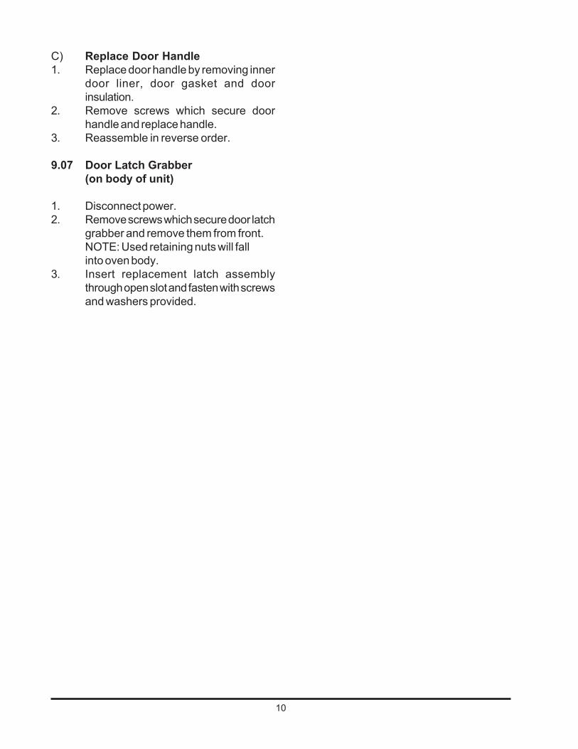
C) Replace Door Handle1. Replace door handle by removing inner
door liner, door gasket and doorinsulation.
2. Remove screws which secure doorhandle and replace handle.
3. Reassemble in reverse order.
9.07 Door Latch Grabber(on body of unit)
1. Disconnect power.2. Remove screws which secure door latch
grabber and remove them from front.NOTE: Used retaining nuts will fallinto oven body.
3. Insert replacement latch assemblythrough open slot and fasten with screwsand washers provided.

11
E1GROUND
CONTROLTEMPERATURE
THERMOSTAT
LI 1N 3
MED
LOW
OFF
INTERNAL SWITCH CONNECTIONS
WIRING DIAGRAM - MODEL 14 EG
LI 1N 2 & 3
LI 2N 3
HIGH
SAFETY
TN
TN
TN
THERMOSTATCONTROL
TEMPERATURESAFETY
BK
GR
WH
YL
RDBK
WHOR
L1
N
BK RD
3
2
1
LINE CORD ASS'Y
3 HEATSWITCH
LEAD ASSY.
LIGHT ASSY. 2 PLACES
LEAD ASSY
THERMOSTAT2 PLACES
HEATER
LEAD ASSY3 PLACES

12
TEMPCONTROL
BLOWERMOTOR
POWERSWITCH
MODELS 25EG, 25EM, 45EG, 45EM
WIRING DIAGRAM
SENSOR SPECS: HEATER115 V
HEATER
318K OHMS @ 0˚C6.6K OHMS @ 100˚C
16001100
HEATER
32.547
HEATER COLD RESISTANCEBETWEEN TB1-4 AND TB1-2
3424744034247439
PART NO. WATTS
TB1-2
TB1-2
TB1-1
TB1-1
TB1-4TB1-3
TB1-2TB1-1
EMR
CHASSIS GROUND
GREEN
230 V
SAFETYCUTOUT LAMP
TEMPCONTROLLAMPEMR-1
WHITE
BLACK
2
1
5
4
SAFETYTHERMOSTAT
OHMS

13
SLEDOMLLA-NEVOYMONOCE-TSILSTRAPTNEMECALPER
LEDOMGE41
LEDOM)LLA(52
LEDOM)LLA(54
PACRETTUHSTNEV 6837713
ELDNAHROOD 3294713
LORTNOCERUTAREPMET,BONK 3094713
C°052-0RETEMOMREHT 6995713
EGNIHPOT 132613
EGNIHMOTTOB 232613
GNIHSUBEGNIHROOD 2267713
TIKFLEHS 2126613 4126613
V511,YSSARETAEH 0545713 1155713 2155713
V022,YSSARETAEH 3745713 1155713 2155713
TIKTNEMECALPERHCTAL 7307613
TROPPUSFLEHS 932613 522613
FLEHSERIW 2737713 5857713
TEKSAGROOD 1864713
TATSOMREHTYTEFAS 4325713
DETHGIL-NON,TSPD,HCTIWS A/N 8135713
TAEH3,HCTIWS 9625713 A/N
81-61/5,TOOFGNILEVEL 6335713
RELLORTNOCERUTAREPMET 4325713 0376713
ROSNESERUTAREPMET A/N 5376713
SSENRAHNEVOYMONOCE A/N 7276713
NOITISOP6KCOLBMRET A/N 6145713
ELGNATROPPUSROOD 632613
ELGNAREKIRTSROOD 732613
V511,YLBMESSATHGIL 5342613 3342613
V032,YLBMESSATHGIL 6342613 4342613
GNIGAKCAPNEVO,TIK 9927613 2527613 3527613
V511TESDROC 1845613 2556713 2656713
V022TESDROC 8845613 9556713
YLNOSLEDOMLACINAHCEM
LEEHWREWOLB A/N 7985713
V511,YSSAROTOM A/N 7896613
V032,YSSAROTOM A/N 5107613

THERMO ELECTRON CORPORATION STANDARD PRODUCT WARRANTYThe Warranty Period starts two weeks from the date your equipment is shipped from our facility. This allows for shipping timeso the warranty will go into effect at approximately the same time your equipment is delivered. The warranty protectionextends to any subsequent owner during the first year warranty period.
During the first year, component parts proven to be non-conforming in materials or workmanship will be repaired or replacedat Thermo's expense, labor included. Installation and calibration are not covered by this warranty agreement. The TechnicalServices Department must be contacted for warranty determination and direction prior to performance of any repairs.Expendable items, glass, filters and gaskets are excluded from this warranty.
Replacement or repair of components parts or equipment under this warranty shall not extend the warranty to either theequipment or to the component part beyond the original warranty period. The Technical Services Department must give priorapproval for return of any components or equipment. At Thermo's option, all non-conforming parts must be returned toThermo Electron Corporation postage paid and replacement parts are shipped FOB destination.
THIS WARRANTY IS EXCLUSIVE AND IN LIEU OF ALL OTHER WARRANTIES, WHETHER WRITTEN, ORAL ORIMPLIED. NO WARRANTIES OF MERCHANTABILITY OR FITNESS FOR A PARTICULAR PURPOSE SHALL APPLY.Thermo shall not be liable for any indirect or consequential damages including, without limitation, damages relating to lostprofits or loss of products.
Your local Thermo Sales Office is ready to help with comprehensive site preparation information before your equipmentarrives. Printed instruction manuals carefully detail equipment installation, operation and preventive maintenance.
If equipment service is required, please call your Technical Services Office at 1-888-213-1790 (USA and Canada) or 1-740-373-4763. We're ready to answer your questions on equipment warranty, operation, maintenance, service and special appli-cation. Outside the USA, contact your local distributor for warranty information.
Rev. 2 1/03
ISO9001REGISTERED