Installation/Owner’s Manual Series 9000Series 9000 › sites › default › files › ...4...
52
Installation/Owner’s Manual Series 9000 Series 9000 Series 9000 Copyright 2009 DoorKing, Inc. All rights reserved. Copyright 2020 DoorKing ® , Inc. All rights reserved. Use this manual for circuit board 4405-018 Revision A or higher. Vehicular Slide Gate Operator Conforms To UL STD 325 Certified To CSA STD C22.2 # 247 Entrapment Protection must be provided for the gate system where the risk of entrapment or obstruction exists. The operator will NOT run without one or more monitored type B1 or B2 entrapment protection devices in EACH direction of gate travel. UL 325 August 2018 Standard THIS PRODUCT IS TO BE INSTALLED AND SERVICED BY A TRAINED GATE/DOOR SYSTEMS TECHNICIAN ONLY. Visit www.doorking.com/dealer-locator to find a professional installing and servicing dealer in your area. Circuit Board Serial Number and Revision Letter: Date Installed: Installer/Company Name: Phone Number: Leave manual with owner : Property owner checklist in back of manual for new installation verification 9000-065-H-5-20
Transcript of Installation/Owner’s Manual Series 9000Series 9000 › sites › default › files › ...4...

Installation/Owner’s Manual Series 9000Series 9000Series 9000
Copyright 2009 DoorKing, Inc. All rights reserved.
Copyright 2020 DoorKing®, Inc. All rights reserved.
Use this manual for circuit board 4405-018 Revision A or higher.
Vehicular Slide Gate Operator
Conforms To UL STD 325
Certified To CSA STD C22.2 # 247
Entrapment Protection must be provided for the gate system where the risk of entrapment or obstruction exists. The operator will NOT run without one or more monitored type B1 or B2 entrapment protection devices in EACH direction of gate travel.
UL 325 August 2018 Standard
THIS PRODUCT IS TO BE INSTALLED AND SERVICED BY A TRAINED GATE/DOOR SYSTEMS TECHNICIAN ONLY. Visit www.doorking.com/dealer-locator to find a professional installing and servicing dealer in your area.
Circuit BoardSerial Numberand Revision Letter:
Date Installed:
Installer/Company Name:
Phone Number:
Leave manual with owner : Property owner checklist in back of manual for new installation verification
9000-065-H-5-20

9000-065-H-5-202 Quick Guide - 1
QUICK GUIDE: DIP-Switches See page 21 for more information about DIP-switches.
Switch Function Setting DescriptionSW 1 (Top 8 Switches)
PrimaryOperatorOpeningDirection
OFFON
OFF
ON
OFF
ON
OFFON
7-OFF7-OFF7-ON7-ON
8-OFF8-ON
8-OFF8-ON
Auto-CloseTimer
Single OperatorDual Operators
Relay
1
2
3
4
5
6
7 and 8
The output wired to terminal #4 becomes the output from the exit loop detector plugged into the EXIT Loop port.Normal Setting. Terminal #4 is a normal full open input.Auto-close timer is OFF. Manual input required to close gate.Normal Setting. Auto-close timer is ON. Adjustable from 1-23 seconds.
Normal Setting. Switch must be OFF for single operator. Switch must be ON when primary/secondary (dual) gates are used.
Normal Setting. Relay activates when gate is at open limit. Relay activates when gate is not closed.Relay activates when gate is opening and open. Relay activates during opening and closing cycle.
Switch Function Setting DescriptionSW 2 (Bottom 4 Switches)
Normal Setting. Switch 3 MUST be turned ON for Model 9000 operator.Normal Setting. Switch 4 MUST be turned OFF for Model 9000 operator.
OFFON
OFFON
ONOFF
Magnetic lock
1
2
34
Normal Setting. Magnetic lock is not used. Magnetic lock is used and connected to terminals 9 and 12. See page 31 for wiring.
Opening directionusing ON setting.
Opening directionusing OFF setting. Changes direction operator will cycle open
upon initial AC power up and open command.
Changes direction operator will cycle open upon initial AC power up and open command.
Opening directionusing ON setting.
Opening directionusing OFF setting.
SecondaryOperatorOpeningDirection
Reverses Gate
Stops Gate
Quick-CloseTimer Override
Exit Loop PortOutput
Full Open Input
Normal Setting. Input to terminal #6 and reverse loop will reverse gate during close cycle.Input to terminal #6 and/or reverse loop will stop gate during close cycle – gate will continue to close after input to terminal #6 and/or reverse loop are cleared (Helps prevent tailgating).
The two DIP-switches located on the circuit board are used to program the operator to operate in various modes and to turn on or off various operating features. Whenever a switch setting is changed, power to the operator must be turned OFF and then turned back on for the new setting to take affect. Check and review ALL switch settings prior to applying power to the operator.
Normal Setting. Timer will function normally.Opening gate will stop and begin to close as soon as all reversing inputs (Reverse loops, photo sensors) are cleared regardless of the distance the gate has opened.

9000-065-H-5-20 3Quick Guide - 2
QUICK GUIDE: Terminal DescriptionsSee page 31 for terminal wiring.
1 ON
SW1
23
4
NC NOSENSE
MARY
4405-018
2
4
5
6
7
8
20
1 ON
SW2
23
45
67
8
OB
CB
OE
CE
G
G
1
ON 1477-010SW1
2 3 4
1
2
3
4
20
19181716
151413
121110
9876
5432
1 Low Voltage Common
Full Open
24 VAC - 250 mA max.
Full Open
Full Open
Standard Reverse or Stop
Gate Tracker Data
Gate Tracker Busy
24 VDC Mag Lock Power
Dry Relay Contact
Dry Relay Contact
Low Voltage Common
Low Voltage Common
Entrapment Alarm
Alarm Reset
Secondary Current Sensor
Motor
Motor
Circuit Board Power
Circuit Board Power
24-volt DC magnetic lock power is provided constantly except when the gate is opening or open (Normally Closed function). 1 Amp Max.
DANGERHIGH VOLTAGE!
• lf SW 1, switch 3 is ON, functions as a normal full open input (Normal setting).
• lf SW 1, switch 3 is OFF, input to terminal #4 becomes the output from the EXIT loop detector plugged into the EXIT loop port. (Used for specialized functions).
SW 1
1 ON2
34
56
78
Operation of relay is dependent on setting of SW 1, switches 7 and 8. Relay contacts can be set for Normally Open (NO) or Normally Closed (NC) operation.
Contact rating is1 amp maximumat 24-volts DC.
NONC
SW 1
1 ON2
34
56
78
This input ONLY functions when gate is fully opened or in the closing cycle.
• When gate is closing: SW 1, switch 5 is OFF, an input to terminal #6 (N.O.) will reverse and open the gate.Note: If the auto-close timer is ON, when gate reaches the open position, timer will not close the gate. Another input command is needed to reset and close the gate.
• When gate is closing: SW 1, switch 5 is ON, an input to terminal #6 (N.O.) will stop the gate, then continue to close the gate when input is clear (Used to help prevent tailgating vehicles from unauthorized entry). See page 21 for more information.
SW 1
1 ON2
34
56
78
Open LEDClose LEDStop LED
Open N.O.Close N.O.Stop N.C.Common
4-Pin Non-Removable Terminal
20-Pin Main Terminal
1234
Jumper on bottom 2 pins when using 4-pin terminal.
Jumper on top 2 pins when NOT using 4-pin terminal.
Notes:• Use a standard 4-wire 3-button control station.DoorKing’s 3-wire 3-button control station cannot be used.
• When using a 3-button control station AND a interlock device together, #3 terminal (N.C.) must be wired in series.
• See page 31 for wiring.
3-Pin withJumper
RelayContacts
4
6
9
1011
16
UL 325 TerminalPages 25-28
For dual operator applications ONLY. Allows the secondary reversing sensor to monitor the current flow into the
secondary operator. See page 24 for more information.
Main Terminal #3 Note:Exceeding 250 mA of power from this terminal may cause the circuit board transformer to overheat, causing intermittent problems.
(See note below)

9000-065-H-5-204
17.7”
28”
19”
OPERATOR SPECIFICATIONSGa
te F
ram
e
4” Minimum Concrete Pad Concrete Pad
Class of Operation UL 325 Class I, II, III, IV Type of Gate Vehicular Slide Gates OnlyDrive Sprocket Size #40 Chain Inherent Entrapment Protection Device Inherent Reverse Sensor System (Type A)External Entrapment Protection Device Inputs Connection inputs for Non-contact Sensor - Photo Sensor (Type B1) (Monitored Inputs) Connection input for Contact Sensor - Reversing Edge (Type B2)
AmpHorsepower - Volts - PhaseModel # Max Gate WeightInstalled Level
Max Gate LengthInstalled Level
Primary Operator1/2 HP - 115 VAC 1-Phase
Secondary Operator1/2 HP - 115 VAC 1-Phase
9000-380
9000-381
1,000 Lbs.
1,000 Lbs.
35 Ft.
35 Ft.
Cycles Per Hour
60
60
Speed
1 Ft/Sec
1 Ft/Sec
5.4
5.4
Primary Operator1 HP - 115 VAC 1-Phase
Secondary Operator1 HP - 115 VAC 1-Phase
9000-385
9000-386
1,500 Lbs.
1,500 Lbs.
35 Ft.
35 Ft.
60
60
1 Ft/Sec
1 Ft/Sec
9.7
9.7
Gate Installed Level
Use this manual for the Model 9000 operators with circuit board 4405-018 Rev A or higher ONLY.
DoorKing, Inc. reserves the right to make changes in the products described in this manual without notice and without obligation of DoorKing, Inc. to notify any persons of any such revisions or changes. Additionally, DoorKing, Inc. makes no representations or warranties with respect to this manual. This manual is copyrighted, all rights reserved. No portion of this manual may be copied, reproduced, translated, or reduced to any electronic medium without prior written consent from DoorKing, Inc.
Type of wiring to be used on ALL external devices:A) Type CL2, CL2P, CL2R, or CL2X. B) Other cable with equivalent or better electrical,mechanical, and flammability ratings.
Entrapment Protection must be provided for the gate system where the risk of entrapment or obstruction exists. The operator will NOT run without one or more monitored type B1 or B2 external entrapment protection devices in EACH direction of gate travel (minimum of 2 external devices required).
Note: 208/230/460/575 VAC input voltage can be connected to the operator by installing an “Optional” High Voltage Kit on the PRIMARY operator ONLY (P/N 2600-266).
7.75”Chain Height:Idler wheels intop position.

9000-065-H-5-20 1
SECTION 1 - INSTALLATION 8889
10-12131414151616
1.1 Hardware for the Gate1.2 Underground Conduit Requirements1.3 Gate Types1.4 Operator Mounting Positions1.5 Concrete Pad Setup or Optional Post Mount Kit1.6 Positioning Operator and Chain1.7 Attaching Operator and Chain1.8 Endless Idler Assembly (On Select Installations)1.9 DoorKing’s Chain Tray Kit1.10 Installation of Warning Signs
SECTION 2 - AC POWER TO OPERATOR 171718
2.1 AC Power Wire Runs and Terminal Connection2.2 Bi-Parting Gates Wiring - Dual Gate Operators
SECTION 8 - OWNER OF THE GATE OPERATOR 424243444547
8.1 Alarm Sounding and Gate WILL NOT Operate8.2 Manual Gate Operation8.3 Gate Operators Monthly Checkup8.4 New Installation Checklist for Installer and Property Owner Printable Safety Page
SECTION 5 - MAIN TERMINAL WIRING 303031
5.1 Terminal Descriptions5.2 Control Wiring
SECTION 7 - MAINTENANCE AND TROUBLESHOOTING 357.1 Maintenance7.2 Built-In Diagnostics7.3 Troubleshooting7.4 Accessory ItemsModel 9000 Wiring Diagrams
3535
36-3738-3940-41
SECTION 6 - OPERATING INSTRUCTIONS 326.1 Operator Controls and Resets6.2 Shutdown Conditions6.3 Manual Gate Operation
323334
SECTION 3 - ADJUSTMENTS 193.1 4405 Circuit Board Descriptions and Adjustments3.2 DIP-Switch Settings for 4405 Circuit Board3.3 Limit Switches3.4 Inherent Reverse Sensor Adjustment3.5 Secondary Current Sensor Adjustment (Dual Gates ONLY)
1920-21
222324
SECTION 4 - ENTRAPMENT AND SAFETY PROTECTION 254.1 UL 325 Terminal Description4.2 Entrapment Protection Device Locations4.3 Dual Gates Multiple Reversing Edges Wiring Sample4.4 Loop Detector Wiring
2526-27
2829
TABLE OF CONTENTS
Quick Guide: DIP-SwitchesQuick Guide: Terminal DescriptionsOperator SpecificationsSlide Gate RequirementsSafety Information for Slide Gate OperatorsASTM 2200 Standard for Gate ConstructionImportant Safety InstructionsInstructions regarding intended installation:Important NoticesUL325 Entrapment ProtectionGlossary
Quick Guide-1Quick Guide-2Previous Page
23444567
QUICK GUIDES

9000-065-H-5-202
Slide Gate Requirements
All openings of a horizontal slide gate are guarded or screened from the bottom of the gate toa minimum of six (6) feet (1.83 m) above the ground to prevent a 2 1/4 inch (57.2 mm) diameter sphere from passing through the openings anywhere in the gate and in that portion of the adjacent fence that the gate covers in the open position.
Note: A filler post or barrier may need to be installed in the gap area to reduce the distance to 2 1/4 inches or less.Install a contact sensor in this area for safety. (See on next page and page 26).
A gap, measured in the horizontal plane parallel to the roadway, between a fixed stationary object
nearest the roadway (such as a gate support post) and the gate frame when the gate is in either the
fully open position or the fully closed position, shall not exceed 2 1/4 inch (57.2 mm).
Closed Gate
2 1/
4” m
axim
um g
ap a
rea
High
Ris
k of
Ent
rapm
ent A
rea
High Risk of Entrapment Area X X X X X X X X X X X X X X X X X X X X X X X X X X X X X X X X X X X X X X X X X X X X X X X X X X X X X X X
X X X X X X X X X X X X X X X X X X X X X X X X X X X X X X X X X X X X X X X X X X X X X X X X X X X X
X X X
Adjacent fence that covers open gate position.
Gate
Sup
port
Post
Gate
Fra
me
A
Illustrations not to scale.
Gates shall be designed, constructed and installed to not fall over more than 45
degrees from the vertical plane, when a gate is detatched from the supporting hardware.
Guid
e
Rolle
rs
Fall Over BracketScreened Wire Mesh Less than 2 1/4”
DoorKing recommends installing screened wire mesh on the ENTIRE gate AND and on that portion of the adjacent fence that the gate covers in the open position. (See above).
This operator is intended for installation only on gates used for vehicles. Pedestrians must be supplied with a separate access opening. For pedestrian access in the vicinity of an automated vehicular gate, separate pedestrian access shall be provided or available. The pedestrian access shall be in a location such that a pedestrian shall not come in contact with a moving vehicular gate access gate during the entire path of travel of the vehicular gate. A pedestrian gate shall not be incorporated into an automated vehicular gate panel.

9000-065-H-5-20 3
ReverseLoop
AutomaticExit Loop
Minimizes the potential of the gate closing when a vehicle is present. Number and placement of loops is dependent on the application.
ReverseLoop
Minimizes the potential of the gate closing when a vehicle is present. Number and placement of loops is dependent on the application.
(Optional) will provide an open command to the gate operator(s) when a vehicle is exiting the property.
Warning Sign
Moving Gate Can CauseSerious Injury or DeathKEEP CLEAR! Gate may move at any timewithout prior warning.Do not let children operate the gate or playin the gate area.This entrance is for vehicles only.Pedestrians must use separate entrance.
Moving Gate Can CauseSerious Injury or DeathKEEP CLEAR! Gate may move at any timewithout prior warning.Do not let children operate the gate or playin the gate area.This entrance is for vehicles only.Pedestrians must use separate entrance.
11
A
B
C
Closed Gate
Secure Side of Gate
Non-Secure Side of Gate
2
Safety Information for Slide Gate Operators
Physical Stop
Positive stops shall be required to limit travel to the designed fully open and fully closed positions. These stops shall be installed either at the top of the gate, or at the bottom of the gate where such stops shall horizontally or vertically project no more than is required to perform their intended function.
Physical Stops
Permanently mounted and easily visible from either side of the gate.
Warning Signs
Non-Contact Sensors (Photo Sensors)1
2
Entrapment protection devices are required to reduce the risk of injury. Install sensors where the risk of entrapment or obstruction exists while gate is moving. Individual requirements will vary. See pages 25-29 for more information on typical layout locations and setup.
Contact Sensor (Reversing Edges)A
B
C
Guide RollersSee previous page for more information.
SeparatePedestrian
WalkwayLocated so pedestrians cannot come in contact with the vehicular gate.
High
Ris
k of
Ent
rapm
ent A
rea
X X
X
X X
X X
X X
X X
X
ScreenedWire MeshMay be necessary on part of fence AND entire gate. See previous page for more information.
Fenc
eFe
nce
Illustration not to scale.
External entrapment protection devices are REQUIRED for operator to function. see page 25
Helps minimize the potential of entrapment during the closing cycle of the gate. Minimizes the potential of the gate closing on vehicular or other traffic that loops cannot sense.
Installed on the fence to help minimize the potential of entrapment between the gate and fence during the opening cycle of the gate. A filler post or barrier MAY need to be installed between fence and gate.
Helps minimize the potential of entrapment during the back travel of the gate (opening cycle).
Helps minimize the potential of entrapment during the back travel of the gate (opening cycle). See previous page for gate gap information.
Helps minimize the potential of entrapment during the closing cycle of the gate. Minimizes the potential of the gate closing on vehicular or other traffic that loops cannot sense. It can be installed on the secure OR non-secure side of gate.

9000-065-H-5-204
Instructions regarding intended installation:
Vehicular gates should be constructed and installed in accordance with ASTM F2200; Standard Specification for Automated Vehicular Gate Construction. For a copy of this standard, contact ASTM directly at 610-832-9585; [email protected]; or www.astm.org.
Important Safety InstructionsWARNING - To reduce the risk of injury or death:1. READ AND FOLLOW ALL INSTRUCTIONS.2. Never let children operate or play with gate controls. Keep the remote control away from children.3. Always keep people and objects away from gate. NO ONE SHOULD CROSS THE PATH OF THE MOVING GATE.4. Test the operator monthly. The gate MUST reverse on contact with a rigid object or stop or reverse when an object activates the non-contact sensors. After adjusting the force or the limit of travel, retest the gate operator. Failure to adjust and retest the gate operator properly can increase the risk of injury or death.5. Use the emergency release only when the gate is not moving.6. KEEP GATES PROPERLY MAINTAINED. Read the owner's manual. Have a qualified service person make repairs to gate hardware.7. The entrance is for vehicles only. Pedestrians must use separate entrance.8. SAVE THESE INSTRUCTIONS!
ASTM F2200 Standard for Gate Construction
• Install the gate operator only if: 1. The operator is appropriate for the construction of the gate and the usage class of the gate. 2. All openings of a horizontal slide gate are guarded or screened from the bottom of the gate to a minimum of 6 feet (1.83 m) above the ground to prevent a 2 ¼ inch (57.2 mm) diameter sphere from passing through the openings anywhere in the gate, and in that portion of the adjacent fence that the gate covers in the open position. 3. All exposed pinch points are eliminated or guarded. 4. Guarding is supplied for exposed rollers. • The operator is intended for installation only on gates used for vehicles. Pedestrians must be supplied with a separate access opening. The pedestrian access opening shall be designed to promote pedestrian usage. Locate the gate such that persons will not come in contact with the vehicular gate during the entire path of travel of the vehicular gate. • The gate must be installed in a location so that enough clearance is supplied between the gate and adjacent structures when opening and closing to reduce the risk of entrapment. Swinging gates should not open into public access areas.• The gate must be properly installed and work freely in both directions prior to the installation of the gate operator. Do not over-tighten the operator clutch, pressure relief valve or reduce reversing sensitivity to compensate for a damaged gate.• For gate operators utilizing Type D protection: 1. The gate operator controls must be placed so that the user has full view of the gate area when the gate is moving. 2. A warning placard shall be placed adjacent to the controls. 3. An automatic closing device (such as a timer, loop sensor, or similar device) shall not be employed. 4. No other activation device shall be connected.• Controls intended for user activation must be located at least six feet (6’) away from any moving part of the gate and where the user is prevented from reaching over, under, around or through the gate to operate the controls. Outdoor or easily accessible controls should have a security feature to prevent unauthorized use.• The Stop and/or Reset button must be located in the line-of-sight of the gate. Activation of the reset control shall not cause the operator to start.• A minimum of two (2) WARNING SIGNS shall be installed, one on each side of the gate where easily visible.• For gate operators utilizing a non-contact sensor: 1. See the instructions on the placement of non-contact sensors for each type of application. 2. Care shall be exercised to reduce the risk of nuisance tripping, such as when a vehicle trips the sensor while the gate is still moving in the opening direction.
3. One or more non-contact sensors shall be located where the risk of entrapment or obstruction exist, such as the perimeter reachable by a moving gate or barrier.• For gate operators utilizing contact sensors: 1. One or more contact sensors shall be located where the risk of entrapment or obstruction exist, such as at the leading edge, trailing edge, and post mounted both inside and outside of a vehicular horizontal slide gate. 2. One or more contact sensors shall be located at the bottom edge of a vehicular vertical lift gate. 3. One or more contact sensors shall be located at the pinch point of a vehicular vertical pivot gate. 4. A hardwired contact sensor shall be located and its wiring arranged so that the communication between the sensor and the gate operator is not subjected to mechanical damage. 5. A wireless contact sensor such as one that transmits radio frequency (RF) signals to the gate operator for entrapment protection functions shall be located where the transmission of the signals are not obstructed or impeded by building structures, natural landscaping or similar obstructions. A wireless contact sensor shall function under the intended end-use conditions. 6. One or more contact sensors shall be located at the bottom edge of a vertical barrier (arm).• Be sure you have instructed the owner of the gate operator about safe and proper operation and testing of the gate operator.
9000-065-H-5-20 5
Vehicular gate operator products provide convenience and security. However, gate operators must use high levels of force to move gates and most people underestimate the power of these systems and do not realize the potential hazards associated with an incorrectly designed or installed system.These hazards may include:
• Pinch points
• Entrapment areas
• Reach through hazards
• Absence of entrapment protection devices
• Improperly located access controls
• Absence of vehicle protection devices
• Absence of controlled pedestrian access
In addition to these potential hazards, automated vehicular gate systems must be installed in accordance with the UL 325 Safety Standard and the ASTM F2200 Construction Standard. Most people are unaware of, or are not familiar with, these standards. If an automated vehicular gate system is not properly designed, installed, used and maintained, serious injuries or death can result. Be sure that the installer has instructed you on the proper operation of the gate and gate operator system.Be sure that the installer has trained you on proper and safe operation of this gate operating system and about the basic functions of the required reversing systems associated with your gate operating system and how to test them (see section 8). These include reversing loops, inherent reversing system, electric edges, photoelectric cells, or other external devices.
• This Owner’s Manual is your property. Keep it in a safe place for future reference.
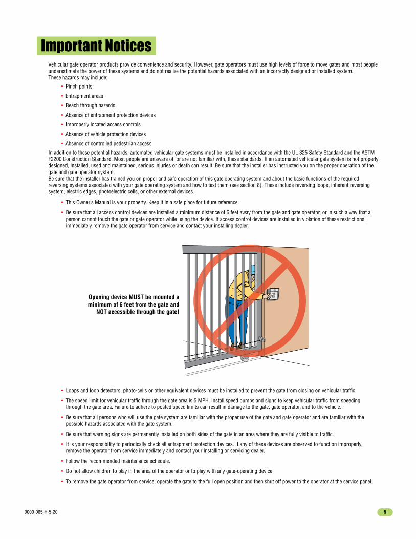
• Be sure that all access control devices are installed a minimum distance of 6 feet away from the gate and gate operator, or in such a way that a person cannot touch the gate or gate operator while using the device. If access control devices are installed in violation of these restrictions, immediately remove the gate operator from service and contact your installing dealer.
Important Notices
• Loops and loop detectors, photo-cells or other equivalent devices must be installed to prevent the gate from closing on vehicular traffic.
• The speed limit for vehicular traffic through the gate area is 5 MPH. Install speed bumps and signs to keep vehicular traffic from speeding through the gate area. Failure to adhere to posted speed limits can result in damage to the gate, gate operator, and to the vehicle.
• Be sure that all persons who will use the gate system are familiar with the proper use of the gate and gate operator and are familiar with the possible hazards associated with the gate system.
• Be sure that warning signs are permanently installed on both sides of the gate in an area where they are fully visible to traffic.
• It is your responsibility to periodically check all entrapment protection devices. If any of these devices are observed to function improperly, remove the operator from service immediately and contact your installing or servicing dealer.
• Follow the recommended maintenance schedule.
• Do not allow children to play in the area of the operator or to play with any gate-operating device.
• To remove the gate operator from service, operate the gate to the full open position and then shut off power to the operator at the service panel.
Opening device MUST be mounted a minimum of 6 feet from the gate and
NOT accessible through the gate!

9000-065-H-5-206
UL 325 Entrapment Protection
Class I - ResidentialVehicular Gate Operator
Entrapment Protection Types
Class II - Commercial/General AccessVehicular Gate Operator
Class III - Industrial/Limited AccessVehicular Gate Operator
A vehicular gate operator (or system) intended for use in garages or parking areas associated with a residence of one-to four single families.
A vehicular gate operator (or system) intended for use in a commercial location or building such as a multi-family housing unit (five or more single family units), hotel, garages, retail store, or other buildings accessible by or servicing the general public.
A vehicular gate operator (or system) intended for use in an industrial location or building such as a factory or loading dock area or other locations not accessible by or intended to service the general public.
Gate Operator Category
UL 325 Classifications
Type A - Inherent entrapment protection system.
Type B1 - Non-contact sensor (photoelectric sensor or the equivalent).
Type B2 - Contact sensor (edge device or equivalent).
Type C - Inherent force limiting, inherent adjustable clutch or inherent pressure relief device.
Type D - Actuating device requiring constant pressure to maintain opening or closing motion of the gate.
* B1 and B2 means of entrapment protection must be MONITORED.
Vertical Barrier Note: Barrier gate operators (arm) that is not intended to move toward a rigid object closer than 16 inches (406 mm) are not required to be provided with a means of entrapment protection.
Horizontal Slide, Vertical Lift, Vertical Pivot Swing, Vertical Barrier (Arm)
A, B1*, B2* or D A, B1*, B2*, C or D
Effective January 12, 2016
AuthorizedPersonnel ONLY
Class IV - Restricted AccessVehicular Gate OperatorA vehicular gate operator (or system) intended for use in a guarded industrial location or building such as an airport security area or other restricted access locations not servicing the general public, in which unauthorized access is prevented via supervision by security personnel.

9000-065-H-5-20 7
GlossaryGATE - A moving barrier such as a swinging, sliding, raising, lowering, or the like, barrier, that is a stand-alone passage barrier or is that portion of a wall or fence system that controls entrance and/or egress by persons or vehicles and completes the perimeter of a defined area. RESIDENTIAL VEHICULAR GATE OPERATOR – CLASS I - A vehicular gate operator (or system) intended for use in a home of one-to four single family dwelling, or garage or parking area associated therewith. COMMERCIAL / GENERAL ACCESS VEHICULAR GATE OPERATOR - CLASS II - A vehicular gate operator (or system) intended for use in a commercial location or building such as a multi-family housing unit (five or more single family units), hotels, garages, retail store, or other building servicing the general public. INDUSTRIAL / LIMITED ACCESS VEHICULAR GATE OPERATOR - CLASS III - A vehicular gate operator (or system) intended for use in an industrial location or building such as a factory or loading dock area or other locations not intended to service the general public. RESTRICTED ACCESS VEHICULAR GATE OPERATOR - CLASS IV - A vehicular gate operator (or system) intended for use in a guarded industrial location or building such as an airport security area or other restricted access locations not servicing the general public, in which unauthorized access is prevented via supervision by security personnel. VEHICULAR BARRIER (ARM) OPERATOR (OR SYSTEM) - An operator (or system) that controls a cantilever type device (or system), consisting of a mechanical arm or barrier that moves in a vertical arc, intended for vehicular traffic flow at entrances or exits to areas such as parking garages, lots or toll areas. VEHICULAR HORIZONTAL SLIDE-GATE OPERATOR (OR SYSTEM) - A vehicular gate operator (or system) that controls a gate which slides in a horizontal direction that is intended for use for vehicular entrance and exit to a drive, parking lot, or the like. VEHICULAR SWING-GATE OPERATOR (OR SYSTEM) - A vehicular gate operator (or system) that controls a gate which moves in an arc in a horizontal plane that is intended for use for vehicular entrance and exit to a drive, parking lot, or the like. SYSTEM - In the context of these requirements, a system refers to a group of interacting devices intended to perform a common function. WIRED CONTROL - A control implemented in a form of fixed physical interconnections between the control, the associated devices, and an operator to perform predetermined functions in response to input signals. WIRELESS CONTROL - A control implemented in means other than fixed physical interconnections (such as radio waves or infrared beams) between the control, the associated devices, and an operator to perform predetermined functions in response to input signals. INHERENT ENTRAPMENT PROTECTION SYSTEM - A system, examples being a motor current or speed sensing system, which provides protection against entrapment upon sensing an object and is incorporated as a permanent and integral part of the operator. EXTERNAL ENTRAPMENT PROTECTION DEVICE - A device, examples being an edge sensor, a photoelectric sensor, or similar entrapment protection device, which provides protection against entrapment when activated and is not incorporated as a permanent part of an operator. ENTRAPMENT - The condition when an object is caught or held in a position that increases the risk of injury.

9000-065-H-5-208
SECTION 1 - INSTALLATIONPrior to beginning the installation of the slide gate operator, we suggest that you become familiar with the instructions, illustrations, and wiring guide-lines in this manual. This will help insure that your installation is performed in an efficient and professional manner compliant with UL 325 safety and ASTM F2200 construction standards. The proper installation of the vehicular slide gate operator is an extremely important and integral part of the overall access control system. Check all local building ordinances and building codes prior to installing this operator. Be sure your installation is in compliance with local codes.
1.1 Hardware for the GateGood hardware is essential for proper operation of a sliding gate. DoorKing has a full line of gate hardware products that will ensure safe, reliable and long lasting gate operation. The gate must be properly installed and roll smoothly in both directions.
Gate End Retainer - Helps stabilize the end of the gate in the open or closed position.
Endless Idler Assembly with Protective Cover - Helps to minimize a pinch point for a 180° chain return.
Guide Rollers with Protective Covers - Helps to minimize a pinch point on the gate.
Roller Bearing V-Wheelswith Protective Cover - Helps to minimize a pinch point on the gate’s wheel and V-rail.
1.2 Underground Conduit Requirements
DoorKing’s Primary/Secondary Interconnection Cable (Dual Operator Application Only)(Secondary Power and Communication wires)
Loop Lead-In Wires (Low Voltage wire insulation)AC Input Power (High Voltage wire insulation)
Sweeps
Concrete Pad
3/4 Inch Conduit Recommended
PrimaryOperatorPosition
SecondaryOperatorPosition
ElbowNO
SweepYES
• The conduit requirements are for a typical slide gate operator installation (the secondary operator is shown for those applications where a secondary operator may be used). The conduit requirements for your application may vary from this depending on your specific needs.• Use only sweeps for conduit bends. Do not use 90° elbows as this will make wire pulls very difficult and can cause damage to wire insulation. DoorKing recommends using 3/4-inch conduit.• External Entrapment Protection is REQUIRED (photo sensor and/or reversing edge).• Be sure that all conduits are installed in accordance with local codes.• Never run low voltage rated wire insulation in the same conduit as high voltage rated wire insulation.
External Safety Devices, Controls and P.A.M.S. Wires (Low Voltage wire insulation)

9000-065-H-5-20 9
1.3 Typical Gate TypesThe Model 9000 operator is designed to be installed on any of these gate types. See the next 3 pages for specific operator mounting positions.
Box Frame Roller
Cantilever
• Steel or Aluminum.
• 1,500 lb max. weight per gate (1 HP motor).
• Chain tray recommended for gates over 20 ft. (Post mount installation when using a chain tray.)
• Single operator - 35 ft max gate length. Dual operators - 70 ft max gate length.
Box Frame Cantilever
V-Rail V-Wheel Ornamental
Single Operator
Front position with post mount and chain tra
y.
Single Operator
Front position with post mount and chain tra
y.
Single Operator
Front position with post mount and chain tra
y.
Single Operator
Front position with concrete pad.
9000-065-H-5-2010
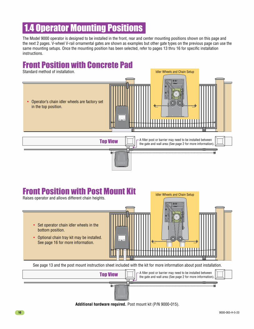
1.4 Operator Mounting Positions
Front Position with Concrete PadStandard method of installation.
Front Position with Post Mount KitRaises operator and allows different chain heights.
Additional hardware required. Post mount kit (P/N 9000-015).
The Model 9000 operator is designed to be installed in the front, rear and center mounting positions shown on this page and the next 2 pages. V-wheel V-rail ornamental gates are shown as examples but other gate types on the previous page can use the same mounting setups. Once the mounting position has been selected, refer to pages 13 thru 16 for specific installation instructions.
Top View
Top View
Idler Wheels and Chain Setup
• Set operator chain idler wheels in the bottom position.
• Optional chain tray kit may be installed. See page 16 for more information.
• Operator’s chain idler wheels are factory set in the top position.
See page 13 and the post mount instruction sheet included with the kit for more information about post installation.
A filler post or barrier may need to be installed between the gate and wall area (See page 2 for more information).
A filler post or barrier may need to be installed between the gate and wall area (See page 2 for more information).
Idler Wheels and Chain Setup

9000-065-H-5-20 11
See page 15 for more information about endless idlers.
EndlessIdler
Top View
Additional hardware required. Endless idler assembly (P/N 2600-818) and additional chain #40 (P/N 2600-442 - 20 ft. per box) may be needed.
Rear Position with Concrete PadHides the chain from outside the property looking in.
Rear Position with Post Mount KitRaises operator and allows different chain heights.
• Set one chain Idler wheel at the center and one in the bottom position.
• Set one chain Idler wheel at the top and one in the center position.
Additional hardware required. Post mount kit (P/N 9000-015). Endless idler assembly (P/N 2600-818)and additional chain #40 (P/N 2600-442 - 20 ft. per box) may be needed.
A filler post or barrier may need to be installed between the gate and wall area (See page 2 for more information).
See page 13 and the post mount instruction sheet included with the kit for more information about post installation.
Idler Wheels and Chain Setup
Idler Wheels and Chain Setup

9000-065-H-5-2012
Additional hardware required. Post mount kit (P/N 9000-015). Endless idler assembly (P/N 2600-818)and additional chain #40 (P/N 2600-442 - 20 ft. per box) may be needed.
Top View
• Set operator chain idler wheels in the bottom position.
Center Position with Post Mount Kit Hides the chain from outside the property looking in.Allows the use of DoorKing’s chain tray kit to attach to gate. This is useful with long gates. It supports the chain’s weight andhelps prevent chain “stretching”.
Gate in Close Position
EndlessIdler
EndlessIdler
Gate in Open Position
Gate shown in open position.
Chain Tray
DoorKing’s Chain Tray Kit for Long GatesSee page 16 for more information.
Gate End Retainer
See page 15 for more information about endless idlers.
See next page and the post mount instruction sheet included with the kit for more information about post installation.
A filler post or barrier may need to be installed between the gate and wall area (See page 2 for more information).
Idler Wheels and Chain Setup

9000-065-H-5-20 13
1.5 Concrete Pad Setup or Post Mounting Concrete Pad Setup
Top View
Side View
Side View
24”
24”17.7”
Minimum Concrete Pad
Extended Concrete Porch(Work Area)
Base Plate
OperatorAttachmentHardware2 Posts
Underground depth of the concrete pad is determined by soil conditions and local building codes. Reinforced concrete recommended.
Concrete pad MUST be level.
Base Plate MUST be level.
8”
ConduitArea
Concrete PadCenter
13”
2” 2”
4.5” 3.5”
4” Minimum
12”
12”
12”
7”
Conduit
4” min. above ground.
Gate
Concrete Pad
Optional Post Mount KitDoorKing offers a post mount kit specifically for the Model 9000 (P/N 9000-015). The kit includes a base plate, 2 posts and hardware to attach the operator to the base plate. This kit will raise the operator and allow different chain heights for specific operator applications. Refer to the instruction sheet provided with the kit for concrete foundation size, conduit type and placement. This kit is needed if a chain tray is required to support the chain’s weight when a longer gate is used (See page 16 for more information about DoorKing’s chain tray kit).
Gate
OptionalChain TrayKit
GateWall
4”
Conc
rete
Fou
ndat
ion
Underground depth of the concrete foundation is determined by soil
conditions and local building codes, 18” minimum depth. Reinforced
concrete recommended.
Operator must be 4” minimum.
3/4” conduitwith sweeps.
18”Min.

9000-065-H-5-2014
1.6 Positioning Operator and Chain
1.7 Attaching Operator and Chain
Operator and chain MUST be parallel to gate!
DoorKing recommends a minimum of four (4) 3/8” x 2” sleeve anchors (not supplied).
Connect Chain Bracketto Gate. Weld completely around bracket. Chain nut and chain bolt should not protrude past gate frame.
Use bolts provided in post mount kit.
Connect chain to chain bolt with master link. Adjust the chain nuts to tighten the chain. The chain should sag no more than one (1) inch per 10 feet of travel. Do not over tighten the chain.
Operator and chain are NOT parallel to gate.
Chain bracket does NOT align with idler wheels.
Chain bracket MUST line up with chain idler wheels!
Chain brackets MUST be mounted so the chain remains the same height as it is on the idler wheels!
Connect Chain to Chain Bracket.
Attaching Operatorto Concrete Pad
Attaching Operatorto Post Mount Plate
ChainBracketLines upwith IdlerWheels
CorrectChain
BracketHeight
CorrectChain
BracketHeight
Chain brackets positionedtoo low.
ChainNut
Chain Bolt
Chain Bracket
Option 1
LockWasher
Washers
3/8
Chainbrackets
positionedtoo high.
ChainIdler Wheels
YESYES
NONO
YESYES
Idler WheelTop Position(Front MountInstallation)
7.75”
Master
Link
Option 2
Gate
Fram
eNONO
NONO
9000-065-H-5-20 15
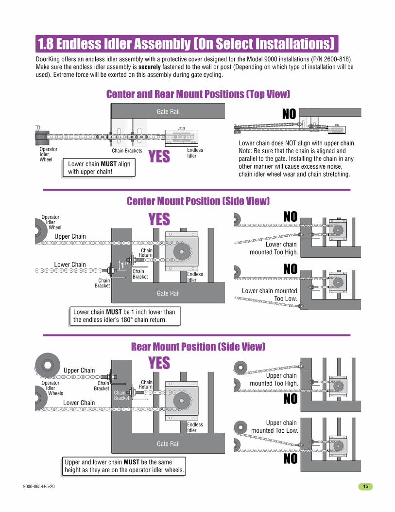
Lower chain does NOT align with upper chain.Note: Be sure that the chain is aligned and parallel to the gate. Installing the chain in any other manner will cause excessive noise, chain idler wheel wear and chain stretching.
Lower chain MUST align with upper chain!
Upper and lower chain MUST be the same height as they are on the operator idler wheels.
NO
NO
NO
1.8 Endless Idler Assembly (On Select Installations)
Gate Rail
Gate Rail
ChainBracket
EndlessIdler
Upper Chain
Lower Chain
ChainBracket
ChainReturn
OperatorIdler
Wheels
OperatorIdler
Wheel
OperatorIdlerWheel
Lower chain mounted Too High.
Lower chain mountedToo Low.
NO
Upper chain mounted Too High.
DoorKing offers an endless idler assembly with a protective cover designed for the Model 9000 installations (P/N 2600-818). Make sure the endless idler assembly is securely fastened to the wall or post (Depending on which type of installation will be used). Extreme force will be exerted on this assembly during gate cycling.
Lower chain MUST be 1 inch lower than the endless idler’s 180° chain return.
Center and Rear Mount Positions (Top View)
Rear Mount Position (Side View)
Center Mount Position (Side View)
Gate Rail
ChainBracket
Chain Brackets
EndlessIdler
EndlessIdler
Upper Chain
Lower ChainChainBracket
ChainReturn
1”
NO
Upper chain mounted Too Low.
YES
YES
YES

9000-065-H-5-2016
1.10 Installation of Warning SignsThis DoorKing Slide Gate Operator is shipped with two warning signs. The purpose of the warning sign is to alert uninformed persons, and to remind persons familiar with the gate system, that a possible hazard exists so that appropriate action can be taken to avoid the hazard or to reduce exposure to the hazard. See page 3 for suggested mounting positions of signs.
• Permanently install the supplied warning signs in locations so that the signs are visible by persons on both sides of the gate.
• Use appropriate hardware such as wood or sheet metal screws (not supplied) to install the warning signs.
1.9 DoorKing’s Chain Tray Kit
The Chain tray supporting brackets can be mounted facing up (as shown) or facing down depending on the operator height.
Chain TraySupportingBracket(Facing down)
Chain TraySupportingBracket(Facing up)
Weep Hole
Carriage Bolts
For further information about the chain tray installation, refer to instructions provided with the chain tray kit.
10 Ft. Segment
Chain TraySegmentsConnection
10 Ft. Segment
A chain tray is recommended for gates longer than 20 ft. to support the weight of the chain. DoorKing offers a chain tray kit in 10 ft. sections to fit any length gate. (DoorKing P/N 2601-270 10 Ft. section)
ChainTray
GateWall
4”
1”
9000-065-H-5-20 17
OFF
ON
AC Power
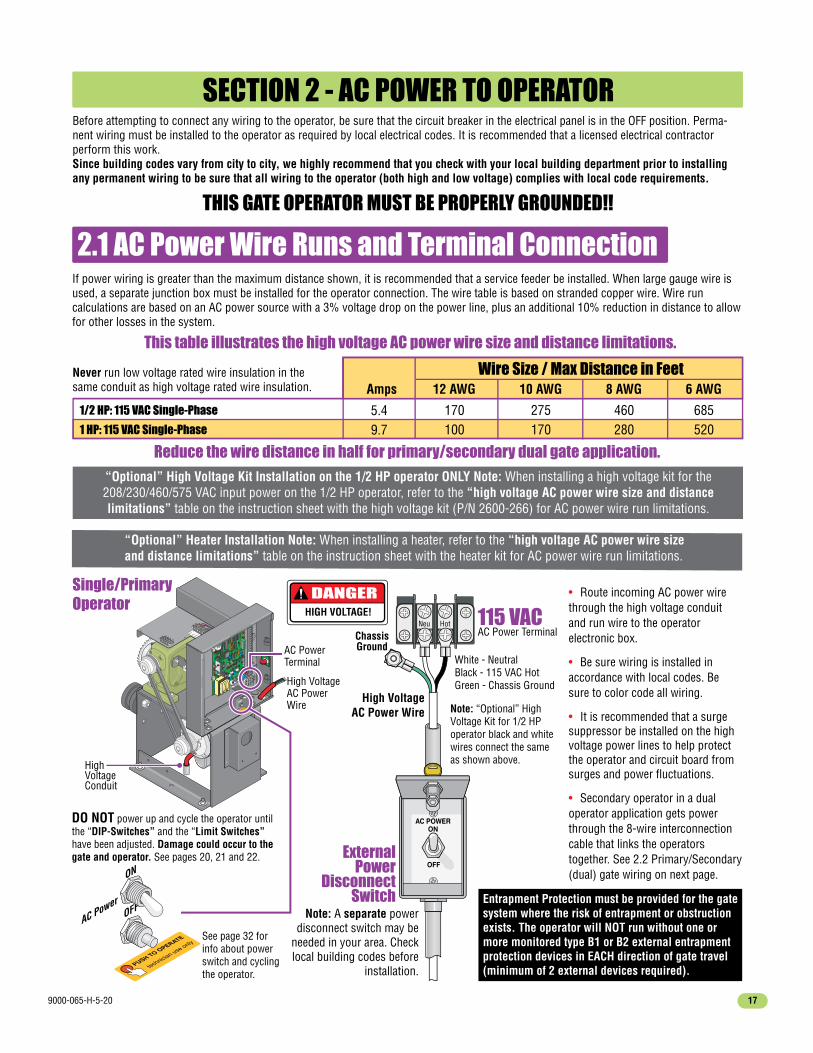
SECTION 2 - AC POWER TO OPERATORBefore attempting to connect any wiring to the operator, be sure that the circuit breaker in the electrical panel is in the OFF position. Perma-nent wiring must be installed to the operator as required by local electrical codes. It is recommended that a licensed electrical contractor perform this work. Since building codes vary from city to city, we highly recommend that you check with your local building department prior to installing any permanent wiring to be sure that all wiring to the operator (both high and low voltage) complies with local code requirements.
THIS GATE OPERATOR MUST BE PROPERLY GROUNDED!!
2.1 AC Power Wire Runs and Terminal ConnectionIf power wiring is greater than the maximum distance shown, it is recommended that a service feeder be installed. When large gauge wire is used, a separate junction box must be installed for the operator connection. The wire table is based on stranded copper wire. Wire run calculations are based on an AC power source with a 3% voltage drop on the power line, plus an additional 10% reduction in distance to allow for other losses in the system.
Reduce the wire distance in half for primary/secondary dual gate application.
Wire Size / Max Distance in FeetAmps 12 AWG
170100
10 AWG
275170
8 AWG
460280
6 AWG
685520
1/2 HP: 115 VAC Single-Phase
1 HP: 115 VAC Single-Phase
5.49.7
115 VACAC Power Terminal
• Route incoming AC power wire through the high voltage conduit and run wire to the operator electronic box.
• Be sure wiring is installed in accordance with local codes. Be sure to color code all wiring.
• It is recommended that a surge suppressor be installed on the high voltage power lines to help protect the operator and circuit board from surges and power fluctuations.
• Secondary operator in a dual operator application gets power through the 8-wire interconnection cable that links the operators together. See 2.2 Primary/Secondary (dual) gate wiring on next page.
PUSH TO OPERATE
technician use only
Power
HighVoltageConduit
AC PowerTerminal
High VoltageAC PowerWire
DANGERHIGH VOLTAGE!
PUSH TO OPERATE
technician use onlySee page 32 for info about power switch and cycling the operator.
DO NOT power up and cycle the operator until the “DIP-Switches” and the “Limit Switches” have been adjusted. Damage could occur to the gate and operator. See pages 20, 21 and 22.
Single/PrimaryOperator
“Optional” Heater Installation Note: When installing a heater, refer to the “high voltage AC power wire size and distance limitations” table on the instruction sheet with the heater kit for AC power wire run limitations.
Never run low voltage rated wire insulation in the same conduit as high voltage rated wire insulation.
This table illustrates the high voltage AC power wire size and distance limitations.
“Optional” High Voltage Kit Installation on the 1/2 HP operator ONLY Note: When installing a high voltage kit for the 208/230/460/575 VAC input power on the 1/2 HP operator, refer to the “high voltage AC power wire size and distance limitations” table on the instruction sheet with the high voltage kit (P/N 2600-266) for AC power wire run limitations.
ChassisGround
HotNeu
White - NeutralBlack - 115 VAC HotGreen - Chassis Ground
Note: A separate power disconnect switch may be
needed in your area. Check local building codes before
installation.
Note: “Optional” High Voltage Kit for 1/2 HP operator black and white wires connect the same as shown above.
High VoltageAC Power Wire
ExternalPower
DisconnectSwitch
AC POWERON
OFF
Entrapment Protection must be provided for the gate system where the risk of entrapment or obstruction exists. The operator will NOT run without one or more monitored type B1 or B2 external entrapment protection devices in EACH direction of gate travel (minimum of 2 external devices required).

9000-065-H-5-2018
PUSH TO OPERATE
technician use only
Power
Automatic
Exit
Reverse
Primary/secondary
interconnection cable
in underground conduit.
AC power conduit
to primary operator
only.
2.2 Bi-Parting Gates Wiring - Dual Gate Operators
Conduit
Secondary Operator Terminal
Conduit
Primary Operator 8-PinSecondary Interface Terminal
Primary Operator Control Board (4405)
Connect the Primary/Secondary operators together with DoorKing’s interconnection cable (P/N 2600-75x) as shown. High voltage power and low voltage communications are supplied to the secondary operator by DoorKing’s UL approved cable that is run in a single conduit. Two conduits (High voltage and low voltage) will need to be provided to the secondary operator when NOT using DoorKing’s UL listed, wet environment interconnection cable.
• Secondary operator contains NO control board.
• All control, loop detector, safety and auxiliary devices are wired to the primary operator. See page 31 for wiring information.
OperatorChassisGround
(Red) Motor 1 High(Blue) Motor 2 High
(White) Neutral 3 High(Purple) 24VAC 4 Low
(Yellow) Limit 5 Low(Brown) Spare 6 Low(Orange) Limit 7 Low
(Gray) COM 8 Low
Motor 1 High (Red)Motor 2 High (Blue)Neutral 3 High (White)24VAC 4 Low (Purple)Limit 5 Low (Yellow)Spare 6 Low (Brown)Limit 7 Low (Orange)COM 8 Low (Gray)
Secondary OperatorPrimary Operator
Interconnection Cable Wiring
DoorKing’s UL Listed (Wet Environment)
Primary/Secondary Interconnection Cable
Reverse
SW 1,switches 1 and 2 will
be opposite each other. Switch 6MUST be ON, seepage 20.
1
RED
Mot
or
2
BLUE
Mot
or
3
WHI
TENe
utra
l
4
PURP
LE24
VAC
5
YELL
OWLi
mit
6
BROW
NSp
are
7
ORAN
GELi
mit
8
GRAY
COM
1
RED
Mot
or
2
BLUE
Mot
or
3
WHI
TENe
utra
l
4
PURP
LE24
VAC
5
YELL
OWLi
mit
6
BROW
NSp
are
7
ORAN
GELi
mit
8
GRAY
COM
1 ON2
34
56
78
Primary Operator
Secondary Operator
Optional Heater Installation Note: If the optional heaters are to be installed on the operators, run two power wires through the interconnection cable conduit to power the secondary operator’s heater. Refer to the instruction sheet in heater kit for more information.
ChassisGround
1Motor
2Motor
3Neutral
424VAC
5Limit
6Spare
7Limit
8COM
NC NO
2
4
5
6
7
8
20
OB
CB
OE
CE
G
G
1477-010
1
2
3
4
20
19181716
151413
121110
9876
5432
1
9000-065-H-5-20 19
9410Single
Channel
9410Single
Channel
REVERSELOOP
P2
EXITLOOP
LMT
POWER
NC
TIMEDELAY
NOREV SENSEPRIMARY
4405-018
REV SENSESECONDARY
2
4
5
6
7
8
20
1 ON
SW2
23
41 O
NSW
1
23
45
67
8
OB
CB
OE
CE
G
G
1
ON 1477-010SW1
2 3 4
1
2
3
4
FIRE
20
19181716
151413
121110
9876
5432
1
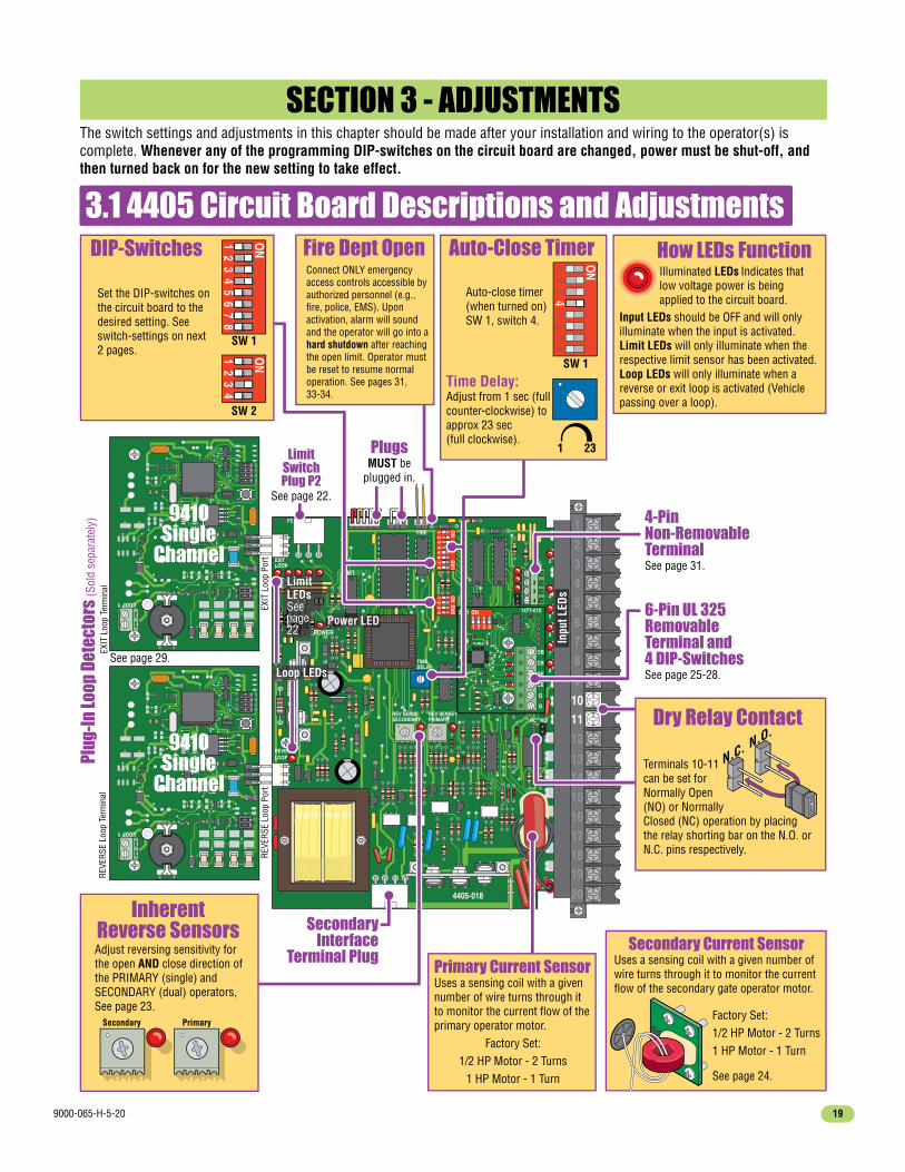
3.1 4405 Circuit Board Descriptions and Adjustments
SECTION 3 - ADJUSTMENTSThe switch settings and adjustments in this chapter should be made after your installation and wiring to the operator(s) is complete. Whenever any of the programming DIP-switches on the circuit board are changed, power must be shut-off, and then turned back on for the new setting to take effect.
Time Delay:Adjust from 1 sec (full counter-clockwise) to approx 23 sec(full clockwise).
Auto-close timer(when turned on) SW 1, switch 4.
Set the DIP-switches on the circuit board to the desired setting. See switch-settings on next 2 pages.
SW 1
SW 1
SW 2
Plug
-In
Loop
Det
ecto
rs (S
old
sepa
rate
ly)
LimitSwitchPlug P2
See page 22.
6-Pin UL 325RemovableTerminal and4 DIP-SwitchesSee page 25-28.
SecondaryInterface
Terminal Plug
1 23
EXIT
Loo
p Te
rmin
alRE
VERS
E Lo
op T
erm
inal
Auto-Close Timer How LEDs FunctionDIP-Switches
Adjust reversing sensitivity for the open AND close direction of the PRIMARY (single) and SECONDARY (dual) operators, See page 23.
InherentReverse Sensors
Power LED
Loop LEDs
Inpu
t LED
s
See page 29.
Illuminated LEDs Indicates that low voltage power is being applied to the circuit board.
Input LEDs should be OFF and will only illuminate when the input is activated.Limit LEDs will only illuminate when the respective limit sensor has been activated. Loop LEDs will only illuminate when a reverse or exit loop is activated (Vehicle passing over a loop).
1 ON2
34
56
78
1 ON2
34
1 ON2
34
56
78
EXIT
Loo
p Po
rtRE
VERS
E Lo
op P
ort
4-PinNon-RemovableTerminalSee page 31.
Primary Current Sensor Uses a sensing coil with a given number of wire turns through it to monitor the current flow of the primary operator motor.
Factory Set:1/2 HP Motor - 2 Turns
1 HP Motor - 1 Turn
Secondary Current Sensor Uses a sensing coil with a given number of wire turns through it to monitor the current flow of the secondary gate operator motor.
Factory Set:1/2 HP Motor - 2 Turns1 HP Motor - 1 Turn
See page 24.
Secondary Primary
N.C. N.O.Dry Relay Contact
Terminals 10-11 can be set for Normally Open (NO) or Normally Closed (NC) operation by placingthe relay shorting bar on the N.O. or N.C. pins respectively.
LimitLEDsSeepage22
Fire Dept OpenConnect ONLY emergency access controls accessible by authorized personnel (e.g., fire, police, EMS). Upon activation, alarm will sound and the operator will go into a hard shutdown after reaching the open limit. Operator must be reset to resume normal operation. See pages 31, 33-34.
PlugsMUST be
plugged in.

9000-065-H-5-2020
3.2 DIP-Switch Settings for 4405 Circuit Board
Switch Function Setting DescriptionSW 1 (Top 8 Switches)
PrimaryOperatorOpeningDirection
OFFON
OFF
ON
OFF
ON
OFFON
7-OFF7-OFF7-ON7-ON
8-OFF8-ON
8-OFF8-ON
Auto-CloseTimer
Single OperatorDual Operators
Relay
1
2
3
4
5
6
7 and 8
The output wired to terminal #4 becomes the output from the exit loop detector plugged into the EXIT Loop port.Normal Setting. Terminal #4 is a normal full open input.Auto-close timer is OFF. Manual input required to close gate.Normal Setting. Auto-close timer is ON. Adjustable from 1-23 seconds.
Normal Setting. Switch must be OFF for single operator. Switch must be ON when primary/secondary (dual) gates are used.
Normal Setting. Relay activates when gate is at open limit. Relay activates when gate is not closed.Relay activates when gate is opening and open. Relay activates during opening and closing cycle.
Switch Function Setting DescriptionSW 2 (Bottom 4 Switches)
Normal Setting. Switch 3 MUST be turned ON for Model 9000 operator.Normal Setting. Switch 4 MUST be turned OFF for Model 9000 operator.
OFFON
OFFON
ONOFF
Magnetic lock
1
2
34
Normal Setting. Magnetic lock is not used. Magnetic lock is used and connected to terminals 9 and 12. See page 31 for wiring.
Opening directionusing ON setting.
Opening directionusing OFF setting. Changes direction operator will cycle open
upon initial AC power up and open command.
Changes direction operator will cycle open upon initial AC power up and open command.
Opening directionusing ON setting.
Opening directionusing OFF setting.
SecondaryOperatorOpeningDirection
Reverses Gate
Stops Gate
Quick-CloseTimer Override
Exit Loop PortOutput
Full Open Input
Normal Setting. Input to terminal #6 and reverse loop will reverse gate during close cycle.Input to terminal #6 and/or reverse loop will stop gate during close cycle – gate will continue to close after input to terminal #6 and/or reverse loop are cleared (Helps prevent tailgating).
The two DIP-switches located on the circuit board are used to program the operator to operate in various modes and to turn on or off various operating features. Whenever a switch setting is changed, power to the operator must be turned OFF and then turned back on for the new setting to take affect. Check and review ALL switch settings prior to applying power to the operator.
Normal Setting. Timer will function normally.Opening gate will stop and begin to close as soon as all reversing inputs (Reverse loops, photo sensors) are cleared regardless of the distance the gate has opened.

9000-065-H-5-20 21
3.2 Continued
Switch 1 Must OPEN the primary operator’s gate upon initial AC power up and open command. If the first open command begins to close the gate, turn AC power off and reverse this switch.
Switch 2 Must OPEN the secondary operator’s gate upon initial AC power up and open command. If the first open command begins to close the gate, turn AC power off and reverse this switch. This switch will be set the opposite of switch 1 (eg. If switch 1 is OFF, then switch 2 will be ON).
Switch 3 Determines that a device wired to terminal #4 is a normal full open command OR terminal #4 becomes the output from the exit loop detector that is plugged into the EXIT Loop port in the circuit board (Used for specialized functions).
Switch 4 Turns the auto-close timer on or off. Maximum time that the close timer can be set for is approximately 23 seconds.
Switch 5 Determines if an input to terminal #6 (e.g.: Normally Open N.O.-Photo Sensors, NOT entrapment protection) AND/OR reverse loops will reverse OR stop a CLOSING gate.A tailgating vehicle can activate terminal #6 and/or reverse loops while the gate is in the closing cycle from the previous vehicle’s authorized entry:If switch 5 is turned OFF (Reverse), the closing gate that gets activated by a tailgating vehicle will reverse back to the open position, possibly allowing the tailgating vehicle unauthorized entry while the gate is reversing back to the open position.If switch 5 is turned ON (Stop), the closing gate that gets activated by a tailgating vehicle will stop, partially or completely blocking the pathway, NOT allowing the tailgating vehicle to enter without proper authorization. The gate will not move until all sensors are clear, usually forcing the tailgating vehicle that activated the sensors to back away from the gate. The gate will then continue until closed, helping prevent the tailgating vehicle from unauthorized entry.
Switch 6 Sets up the circuit board for a single gate operator or primary / secondary (dual) gate operators.
Switches 7-8 These work in conjunction with each other and determine when the relay on the board will be activated. This relay can be used as a switch for various functions such as illuminating a warning light when the gate is moving, or turning on a green light when the gate is full open.
Switch 1 Turning the quick-close feature on will cause the auto close timer to close the gate after 1 second, regardless of the setting of the auto close timer potentiometer. This will also cause an opening gate to stop and reverse when the reverse loops and/or photo sensors are cleared. This feature, along with turning SW 1, switch 5 ON above, is useful to help prevent tailgating vehicles from unauthorized entry.
Switch 2 If a magnetic lock is not used with the gate operator, leave this switch in the OFF position. Turn this switch ON if a magnetic lock is used and connected to terminals 9 and 12. This applies magnetic lock power and logic to these terminals (NC).
Switch 3 MUST be turned ON for the Model 9000.
Switch 4 MUST be turned OFF for the Model 9000.
1 ON2
34
56
78
SW 1 (Top 8 Switches)TypicalSettings
SW 2 (Bottom 4 Switches)TypicalSettings
1 ON2
34
Switch Definitions

9000-065-H-5-2022
P2
EXITLOOP
LimitSwitches
AB
OPP
B
OPP
B
OPP
B
OPPOPPOPPOPPPPP
AAA SecondaryOperator’s
A and B
3.3 Limit Switches
Switch 1 “OFF”
Limit LEDs Upper left corner of Circuit Board.
= Close LimitA
= Open LimitB
Open and Close Limits MUST be Set
SW 1
1 ON2
34
56
78
Switch 1 “ON”
= Open LimitA
= Close LimitB
SW 1
1 ON2
34
56
78
“Opening Direction” DIP-Switch
Note: SW 1, Switch 2 - Secondary operator “Opening Direction” functions the same as switch 1.
Note: If P2 plug is not connected to the circuit board and AC power is turned on, alarm will sound and operator will NOT function.
The operator normally stops a cycling gate using the open and close limits. If the limits have not been set, the gate could continue beyond its full open and close positions, damaging the gate and operator. DO NOT allow this to occur!
P2
Lock-PlatePush
PushB
Limit-Nut
Limit-Nut
A
B
LimitSwitch
LimitSwitch
APush and hold the lock-plate away from the limit-nuts. Rotate the limit-nuts to the desired gate FULL open and close positions. After adjusting, make sure the lock-plate is engaged in the slots on the limit-nuts to prevent them from rotating.
PUSH TO OPERATE
technician use only
Power
Limit SwitchBox

9000-065-H-5-20 23
LED
Test the operator reversing sensitivity:
Dual Operators:
1
2
Place an immobile object along the gate path, allowing the gate to strike it while in the open and close cycles. The gate must reverse direction after striking the object. If it does not, increase the reverse sensitivity and repeat this testing until the correct sensitivity has been achieved in BOTH directions. The operator will assume a soft shutdown (Hold the auto-close timer) after striking and reversing the gate which will require pressing the “Push to Operate” button to cycle the operator again.
3
Adjust reverse sensors for each operator when dual operators have been installed. Secondary Primary
PrimaryMax
Sensitivity
3.4 Inherent Reverse Sensors AdjustmentThis vehicular gate operator is equipped with an inherent adjustable reversing sensor (Type A) used as the primary entrapment protection system according to UL 325 standards. The gate will reverse direction after “physically” encountering an obstruction in either the opening or closing gate cycle.If the Auto-Close Timer (DIP-switch SW 1, switch 4) is ON and the gate physically encounters an obstruction during the CLOSING cycle, it will reverse to the open position and HOLD the gate at this position (Soft shutdown condition). Another input command is needed before the gate will reset and close again.
For the reverse system to function correctly, the gate must be properly installed and work freely in both directions and the limit switches must be properly adjusted before adjusting these sensors. The ideal adjustment will allow the operator to move the gate through its entire travel cycle without reversing, but will reverse upon contact with an obstruction with no more than 40 Lbs of force. This force can be measured with a gate scale.
PUSH TO OPERATE
technician use only
PUSH TO OPERATE
technician use only
Note: “Push to Operate” button will useAuto-Close timer if turned ON.
Note: The LED will turn on briefly when AC power is turned on.
CAUTION: Keep pedestrians and vehicles clear of the gate while adjusting and testing sensors!
Note: If the minimum or maximum reverse sensor sensitivity adjustment is reached and the Secondary Operator will not reverse properly, the Secondary Operator Current Sensor’s wire turns will have to be altered.See 3.5 Secondary Current Sensor Adjustment on the next page.
Safety Note: The LED will remain ON after a cycling gate gets obstructed during normal operation to indicate that the reverse sensor has been tripped. Always check the gate area for possible obstructions before putting operator back in service.
While gate is opening, slowly rotate the primary reverse sensor clockwise until the LED lights up and the gate reverses direction. Rotate the primary reverse sensor back counter-clockwise approximately 1/8 turn to decrease the sensitivity (LED will turn off).
Press the “Push to Operate” button and CLOSE the gate.Make sure the gate closes completely. If it reverses andopens (LED will turn on), rotate the primary reversesensor counter-clockwise a little more to decrease thereverse sensitivity (LED will turn off). Cycle the gate a few times to be sure that it cycles completely in both directions, adjusting the primary sensor as necessary.
Press the “Push to Operate” button to OPEN the gate.
Min

9000-065-H-5-2024
3.5 Secondary Current Sensor Adjustment (Dual Gates ONLY)ONLY the PRIMARY gate operator’s “secondary reversing sensor” uses a secondary current sensing device (Located only in the primary operator) to detect any obstructions “physically” encountered in the SECONDARY gate path when using dual gates. The secondary current sensor uses a sensing coil with a given number of turns through it to monitor the current flow into the secondary operator. Each time the wire passes through the coil, it is considered a turn. The number of turns through the sensing coil is dependant on the operating voltage of the operator and the weight of the gate. In general, light weight gates may require additional turns of wire through the secondary current sensor, while heavier gates may require less turns. CAUTION – HIGH VOLTAGE: Be sure power is turned OFF before changing the number of wire turns to the secondary current sensor. When you are setting the secondary reverse sensor (section 3.4 on the previous page) and reach the MAXIMUM sensitivity position on the reverse sensor without activating the secondary operator reversing function, add an additional turn of wire through the secondary current sensor. If you set the secondary reverse sensor to the MINIMUM sensitivity position and the gate will not cycle completely, reduce the number of turns through the secondary current sensor.
Secondary Operator Model Turns
115 - 1/2 HP - Single-Phase115 - 1 HP - Single-Phase
21
1 Turn
Sample Turns
1
2 Turns
1 2PUSH TO OPERATE
technician use only
Power
SecondaryCurrentSensor locatedonly inprimaryoperator.
Typical Number of Turns forSecondary Current SensorPrimary
Operator
Automatic Exit
Reverse
Reverse
Primary/secondary
interconnection cable
in underground conduit.
Primary Gate
Secondary Gate
1Motor
2Motor
3Neutral
424VAC
5Limit
6Spare
7Limit
8COM
Primary Operator
Secondary OperatorTo AC power terminal.
To AC power terminal.
DANGERHIGH VOLTAGE!

9000-065-H-5-20 25
REVERSELOOP
P2
EXITLOOP
POWER
NC
TIMEDELAY
NOREV SENSEPRIMARY
4405-018
REV SENSESECONDARY
2
4
5
6
7
8
20
1 ON
SW2
23
41 O
NSW
1
23
45
67
8
OB
CB
OE
CE
G
G
1
ON 1477-010SW1
2 3 4
1
2
3
4
FIRE
115 VAC Convenience Outlets
SECTION 4 - ENTRAPMENT AND SAFETY PROTECTION
4.1 UL 325 Terminal Description
Ground (Common): Common terminals for all the external entrapment protection device inputs.
1
2
3
4
5 & 6
Closed Gate
Wall / Fence
Entrapment Area
Closed Gate
Wall / Fence
Entrapment Area
20
19181716
151413
121110
9876
5432
1
Sensor LEDs Note:LED ON: Connected device has been activated. LED remains off during normal operation.LED Flashing: Connected device is in fault. Wiring to device is bad.
6-Pin UL 325 TerminalConnect ONLY MONITORED Devices
OBCBOECEGG
123456
Sensor LEDs
DIP-switches MUST be turned ON for each device wired to terminal.
1
ON
2 3 4
Mointored Device Note: Only 1 monitored Device can be connected to each input.An OPTIONAL Expansion Kit (sold separately) will allow connection for additional devices.
OPEN Beam STOP (Switch 1)CLOSE Beam REVERSE (Switch 2)OPEN Edge/Beam REVERSE (Switch 3)CLOSE Edge/Beam REVERSE (Switch 4)Ground (Common)Ground (Common)
UL 325DIP-Switches
Closed Gate
Wall / Fence
Close Edge
Entrapment Area
Wall / Fence
Closed GateOpen Edge
Entrapment Area
Filler Post if necessary
Open Edge
CLOSE Edge/Beam Reverse: Obstructed reversing edge or photo beam will reverse the gate to the open position during the closing-direction only.
• After the gate reverses to the open position, the close-timer will time out and close the gate (if it is turned on). • If a second sequential obstruction is encountered prior to the gate reaching the close limit, the gate will reverse to full open position and enter a soft shutdown condition (See page 33).
OPEN Edge/Beam Reverse: Obstructed reversing edge or photo beam will reverse the gate to the close position during the opening-direction only. • After the gate reverses to the close position, any opening input will cycle the gate again. Note: If the gate is opening by a time clock and a edge/beam gets obstructed, the gate will return to the closed position and another input (automatic exit loop, reverse loop, remote etc.) is needed to cycle the gate open again.
CLOSE Beam Reverse: Obstructed closing-direction photo beam will reverse the gate to the open position and reset the close-timer during the closing-direction only.Gate will close when timer times out.
OPEN Beam Stop: Obstructed opening-direction photo beam will stop the gate during the opening-direction only. Gate will resume the open cycle when the obstructed photo beam has been cleared.
Open Beam
Open Beam
Close Beam
Close Beam
External Entrapment Protection Devices:In addition to the inherent reversing sensor system, this operator has a UL 325 terminal for the connection of photo sensors-Type B1 and/or reversing edges-Type B2 entrapment protection required by UL 325 standards. Entrapment Protection must be provided for the gate system where the risk of entrapment or obstruction exists. The operator will NOT run without one or more monitored type B1 or B2 external entrapment protection devices installed in EACH direction of gate travel (minimum of 2 external devices required). Install these devices where the risk of entrapment or a safety hazard exists, examples of which are shown below and the next 3 pages. Installations can vary.

9000-065-H-5-2026
Gate
Fra
me
Non-Secure Side Outside Property
Secure Side Inside Property
Filler Post or Barrier
Reversing Edge (Open Contact Sensor)
4.2 Entrapment Protection Device LocationsTypical UL Photo Sensor mounting heightand distance away from gate.
Gate
Fra
me
If the distance between the gateand wall is greater than 2 1/4”.
Wall
UL s
enso
r mou
nted
on
post
.
UL s
enso
r mou
nted
on
wal
l.
A filler post or barrier may need to be installed between the gate and wall area to reduce the distance to 2 1/4” or less. A reversing edge should be installed on the post or barrier for safety (See page 2 for more information).
DIP-switches 1, 2 and 3MUST be ON.
Photo sensors may be installed on either side of gate frame, as close as practical to the gate but no further away than 5”.
No higher than 27.5” above grade.
21” is typical for most installations.
Note: Additional photo sensors can be added above the 27.5” height.
5”or
Less
5”or
Less
1
ON
2 3 4
ONLYconnectmonitoreddevices.
Photo Sensors (With Filler Post and Reverse Edge) Sample Setup
Closed Gate
Wall
Photo Sensor Power Note: Photo sensors can be powered by the built-in convenience outlets located on the operator (See previous page).
Close Beam
Open Beam
6-Pin UL 325Terminal Wiring
Filler Post If necessary
Open Edge
Only 1 monitored Device can be connected to each input. An OPTIONAL Expansion Kit (sold separately) will allow connection for additional devices.
OPEN Beam STOPCLOSE Beam REVERSE
OPEN Edge/Beam REVERSECLOSE Edge/Beam REVERSE
(Common) Ground(Common) Ground
UL 325 DIP-Switches
Type of wiring to be used on ALL external devices:A) Type CL2, CL2P, CL2R, or CL2X. B) Other cable with equivalent or better electrical,mechanical, and flammability ratings.
123456
IMPORTANT: Monitored Photo and Edge sensors must be end-of-line resistive types. See specific manufacturer's wiring manual for more information.
9000-065-H-5-20 27
Wiring Note: Receiver can be wired directly to main terminal if desired.
Power is limited to 250 mA
Com
24 Volt
3-Pin RemoteTerminal20-Pin
MainTerminal
To #1
To #3
1
23
CloseEdge
OpenEdge
OpenBeam
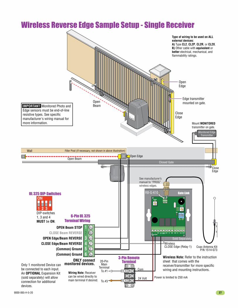
Wireless Reverse Edge Sample Setup - Single Receiver
Closed Gate
Wall
Wireless Note: Refer to the instruction sheet that comes with the receiver/transmitter for more specific wiring and mounting instructions.
CloseEdge
Open Edge
Edge transmitter mounted on gate.
Open Beam
Only 1 monitored Device can be connected to each input. An OPTIONAL Expansion Kit (sold separately) will allow connection for additional devices.
DIP-switches 1, 3 and 4MUST be ON.
1
ON
2 3 4
ONLY connectmonitored devices.
6-Pin UL 325Terminal Wiring
OPEN Beam STOPCLOSE Beam REVERSE
OPEN Edge/Beam REVERSECLOSE Edge/Beam REVERSE
(Common) Ground(Common) Ground
UL 325 DIP-Switches
Mount MONITORED transmitter on gate.
Monitored EdgeTransmitter
Type of wiring to be used on ALLexternal devices:A) Type CL2, CL2P, CL2R, or CL2X. B) Other cable with equivalent orbetter electrical, mechanical, andflammability ratings.
Filler Post (If necessary, not shown in above illustration)
WirelessCLOSE Edge (Relay 1)
ON DIP
1 2 3 4
+ CS1
GND ANT
PROG
C1 BS1 BS2 NO3 C3 ATESTComCS2 C2-
R3
R1
R2
MR
ATEST
CHECK
12/24 AC/DC
Sold Separately
Gate LinkRB-G-K10
123456
Coax Antenna KitP/N 1514-073
See manufacturer’s manual to “PROG” wireless edges.
IMPORTANT: Monitored Photo and Edge sensors must be end-of-line resistive types. See specific manufacturer's wiring manual for more information.

9000-065-H-5-2028
4.3 Dual Gates Multiple Reversing Edges Wiring Sample2
Wire
T2
Term
inat
ion
10K
Edge
Wireless EdgeTransmitter
Wireless EdgeTransmitter
Wireless EdgeTransmitter
Wireless EdgeTransmitter
PROG
RB-TX10
COM
P/N.
C.
10K
COM
P/N.
C.
10K
POW
ER
Output B Output A
IN3
MIM-62Multi-Input Module
IN1
MillerEdge
IN4
IN5
IN6
Input
Com
Pwr+
Pwr-
IN2
Input
Com
Pwr+
Pwr-
Pwr+
Pwr-
Input
Com
Pwr+
Pwr-
Input
Com
Pwr+
Pwr-
Input
Com
Pwr+
Pwr-
Input
Com
Wall / Fence
Wireless Open Edge Wireless Close Edge
Filler PostOpen Edge
Wall / Fence
Wireless Open EdgeWireless Close Edge
Filler PostOpen Edge
9000 UL 325 Terminal
Gate Link
MIM-62 Front
Wireless EdgeTransmitter
MIM-62 Back
OPE
N BE
AMCL
OSE
BEA
MO
PEN
EDG
ECL
OSE
EDG
E
HARDWired HARDWired
Power
Output A
Power
WirelessOPENEdges(Relay 1)
P/N - 8080-079 Multi-InputModule (MIM-62)
P/N - 8080-008 RF MonitoredGate Link Kit (RB-G-K10)
P/N - 8080-006 MonitoredTransmitter RB-TX-10
Miller Edge Sensing Edges -All models with a T2(resistive) termination.
WirelessCLOSEEdges(Relay 2)
ON DIP
1 2 3 4
+ CS1
GND ANT
PROG
C1 BS1 BS2 NO3 C3 ATESTComCS2 C2-
R3
R1
R2
MR
ATEST
CHECK
12/24 AC/DC
POW
ER
COM
P/N.
C.10
KCO
MP/
N.C.
10K
PWR
(+)
PWR
(-)
INPU
T (-
)
INPU
T (+
)
OUT B OUT A
WIRING DIAGRAM
PR
OUT
AOU
T B
1 2
ON
OUTPUTTYPE
LEARNINPUT/OUTPUTASSIGNMENTS
ON
1 2 3 4 5 6
AB
X X 3 4 5 6
Model # MIM-62 Class 2 Device
Set to “R”
Set 3 to “A Output”
Set 4 to “OFF”
Set DIPswitches3,4 to “ON”
See manufacturer’smanual to “LEARN” open edges.
See manufacturer’s manual to “PROG” wireless edges.
Mounton gatenext toedge.
9000 UL 325DIP-Switches
All safety devices MUST be wired to the PRIMARY operator ONLY when using dual gate operators.
OBCBOECEGG
1
ON
2 3 4
OPEN Beam STOP (Switch 1)CLOSE Beam REVERSE (Switch 2)OPEN Edge/Beam REVERSE (Switch 3)CLOSE Edge/Beam REVERSE (Switch 4)Ground (Common)Ground (Common)
123456
Use a 24 VDC power transformer (not supplied) or (U.L. listed equivalent) to power the MIM-62 and Gate Link. (P/N 1812-136)
24 VDC
IMPORTANT: Monitored Photo and Edge sensors must be end-of-line resistive types. See specific manufacturer's wiring manual for more information.

9000-065-H-5-20 29
REVERSELOOP
P2
EXITLOOP
POWER
NC
TIMEDELAY
NOREV SENSEPRIMARY
4405-018
REV SENSESECONDARY
2
4
5
6
7
8
20
1 ON
SW2
23
41 O
NSW
1
23
45
67
8
OB
CB
OE
CE
G
G
1
ON 1477-010SW1
2 3 4
1
2
3
4
20
19181716
151413
121110
9876
5432
1
Automatic ExitReverse4 Ft. m
in. to avoid gate
movement interference.
4 Ft. min. to
avoid gate
movement interference.
4 Ft. min. to
avoid
reverse loop interference.
Loop Lead In Wires
Loop Lead In Wires
Reverse
9410
9410
Note: Loop detector wiring is shown for DoorKing plug-in loop detector (P/N 9410-010 Single Channel). If third party loop detectors are used, refer to the installation instructions supplied with those detectors for wiring and separate power instructions.
Automatic Exit LoopAutomatically opens the gate for exiting vehicles without having to use a transmitter or keypad. The exit loop can be placed a minimum of 4 feet away from the reverse loop or far enough away from the gate so the gate has started opening or even completely opened by the time you drive up to it (Free exit).
4.4 Loop Detector WiringTo help protect the operator from accidentally closing on vehicles in the gate’s path, DoorKing highly recommends that loops and loop detectors be installed. Loops are laid underneath, cut into asphalt or concrete driveways or buried beneath gravel and earth driveways. A loop detection system will sense a vehicle like a metal detector and send a signal to the gate operator preventing the gate from automatically opening or closing on a vehicle when it is in the gate’s path. DoorKing recommends that a licensed installer perform this work.
DoorKingPlug-inLoopDetectors
Single Channel Loop
Single Channel Loop
B
A
Reverse loop lead-in wires are twisted approx. 6 twists per foot and are wired in series.
A
LOOP
1
B
PVC Conduit
LOOP
1
PVC Conduit
DoorKing offers a free “Loop and Loop-Detectors Information Manual” PDF located at DoorKing’s web site for more information. www.doorking.com
4405-018
SW 1
1 ON2
34
56
78
Exit loop lead-in wires are twisted approx. 6 twists per foot.
Reverse LoopsReverse loops are placed on each side of the gate to prevent the gate from closing on a vehicle in the gate’s path. They will stop or reverse the cycling of the gate while a vehicle is in or near the gate’s pathway.
Note: SW 1, switch 5 must be set for the reverse loops. See page 21 for more information about SW 1, switch 5 ON/OFF options.
Exit Loop Port
Reverse Loop Port

9000-065-H-5-2030
1 ON
SW1
23
4
NC NOV SENSEMARY
4405-018
2
4
5
6
7
8
20
1 ON
SW2
23
45
67
8
OB
CB
OE
CE
G
G
1
ON 1477-010SW1
2 3 4
1
2
3
4
20
19181716
151413
121110
9876
5432
1
5.1 Terminal Descriptions
Low Voltage Common
Full Open
24 VAC - 250 mA max.
Full Open
Full Open
Standard Reverse or Stop
Gate Tracker Data
Gate Tracker Busy
24 VDC Mag Lock Power
Dry Relay Contact
Dry Relay Contact
Low Voltage Common
Low Voltage Common
Entrapment Alarm
Alarm Reset
Secondary Current Sensor
Motor
Motor
Circuit Board Power
Circuit Board Power
24-volt DC magnetic lock power is provided constantly except when the gate is opening or open (Normally Closed function). 1 Amp Max.
• lf SW 1, switch 3 is ON, functions as a normal full open input (Normal setting).
• lf SW 1, switch 3 is OFF, input to terminal #4 becomes the output from the EXIT loop detector plugged into the EXIT loop port. (Used for specialized functions).
SW 1
1 ON2
34
56
78
SECTION 5 - MAIN TERMINAL WIRING
This input ONLY functions when gate is fully opened or in the closing cycle.
• When gate is closing: SW 1, switch 5 is OFF, an input to terminal #6 (N.O.) will reverse and open the gate.Note: If the auto-close timer is ON, when gate reaches the open position, timer will not close the gate. Another input command is needed to reset and close the gate.
• When gate is closing: SW 1, switch 5 is ON, an input to terminal #6 (N.O.) will stop the gate, then continue to close the gate when input is clear (Used to help prevent tailgating vehicles from unauthorized entry). See page 21 for more information.
SW 1
1 ON2
34
56
78
Open LEDClose LEDStop LED
Open N.O.Close N.O.Stop N.C.Common
4-Pin Non-Removable Terminal
20-Pin Main Terminal
1234
Jumper on bottom 2 pins when using 4-pin terminal.
Jumper on top 2 pins when NOT using 4-pin terminal.
Notes:• Use a standard 4-wire 3-button control station.DoorKing’s 3-wire 3-button control station cannot be used.
• When using a 3-button control station AND a interlock device together, #3 terminal (N.C.) must be wired in series.
• See next page for wiring.
3-Pin withJumper
RelayContacts
4
6
9UL 325 Terminal
Pages 25-28
Operation of relay is dependent on setting of SW 1, switches 7 and 8. Relay contacts can be set for Normally Open (NO) or Normally Closed (NC) operation.
Contact rating is1 amp maximumat 24-volts DC.
NONC
SW 1
1 ON2
34
56
78
1011
16
DANGERHIGH VOLTAGE!
Main Terminal #3 Note:Exceeding 250 mA of power from this terminal may cause the circuit board transformer to overheat, causing intermittent problems.
(See note below)
For dual operator applications ONLY. Allows the secondary reversing sensor to monitor the current flow into the
secondary operator. See page 24 for more information.
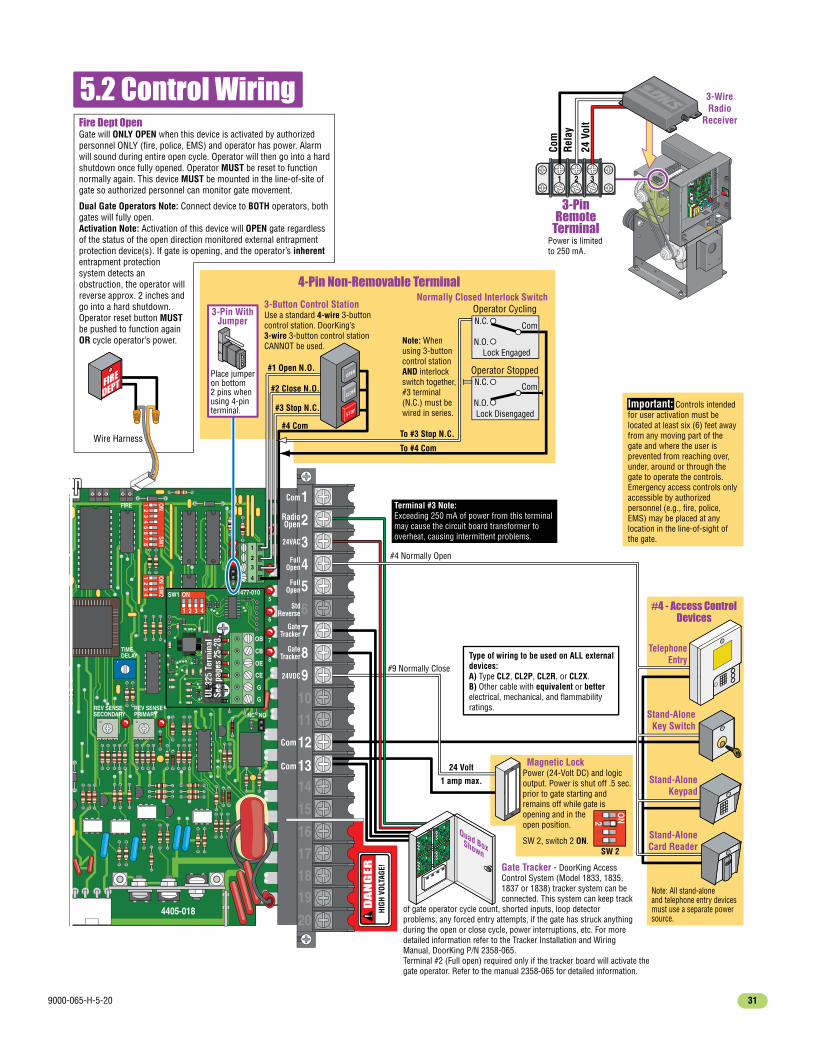
9000-065-H-5-20 31
NC
TIMEDELAY
NOREV SENSEPRIMARY
4405-018
REV SENSESECONDARY
2
4
5
6
7
8
20
1 ON
SW2
23
41 O
NSW
1
23
45
67
8
OB
CB
OE
CE
G
G
1
ON 1477-010SW1
2 3 4
1
2
3
4
FIRE
PUSH TO OPERATE
technician use only
Power
Power is limited to 250 mA.
3-Wire Radio
Receiver
Com
24 V
olt
Rela
y
1Motor
2Motor
3Neutral
424VAC
5Limit
6Spare
7Limit
8COM
3-PinRemote
Terminal
1 2 3
Gate Tracker - DoorKing Access Control System (Model 1833, 1835, 1837 or 1838) tracker system can be connected. This system can keep track
of gate operator cycle count, shorted inputs, loop detector problems, any forced entry attempts, if the gate has struck anything during the open or close cycle, power interruptions, etc. For more detailed information refer to the Tracker Installation and Wiring Manual, DoorKing P/N 2358-065.Terminal #2 (Full open) required only if the tracker board will activate the gate operator. Refer to the manual 2358-065 for detailed information.
#4 - Access ControlDevices
20
19181716
151413
121110
9876
5432
1
Com
Com
Com
5.2 Control Wiring
#4 Com
24 Volt
1 amp max.
Stand-AloneKey Switch
Stand-AloneKeypad
Stand-AloneCard Reader
TelephoneEntry
4-Pin Non-Removable Terminal
Note: All stand-aloneand telephone entry devices must use a separate power source.
Note: When using 3-button control station AND interlock switch together, #3 terminal (N.C.) must be wired in series.
3-Button Control StationUse a standard 4-wire 3-button control station. DoorKing’s 3-wire 3-button control station CANNOT be used.
Normally Closed Interlock Switch
RadioOpen
#3 Stop N.C.
#2 Close N.O.
#1 Open N.O.
To #4 Com
To #3 Stop N.C.
N.O.
N.C. Com
Operator Cycling
Lock Engaged
N.O.
N.C. Com
Operator Stopped
Lock Disengaged
OPEN
STOP
CLOSE
Place jumper on bottom2 pins when using 4-pin terminal.
3-Pin WithJumper
Magnetic Lock
#4 Normally Open
#9 Normally Close
Quad BoxShown
FullOpen
FullOpen
24VDC
24VAC
StdReverse
GateTracker
GateTracker
Power (24-Volt DC) and logic output. Power is shut off .5 sec. prior to gate starting and remains off while gate is opening and in theopen position.
SW 2, switch 2 ON.SW 2
1 ON2
34
UL 3
25 T
erm
inal
See
page
s 25
-28.
DA
NG
ER
HIGH
VOL
TAGE
!
Terminal #3 Note:Exceeding 250 mA of power from this terminal may cause the circuit board transformer to overheat, causing intermittent problems.
Type of wiring to be used on ALL externaldevices:A) Type CL2, CL2P, CL2R, or CL2X. B) Other cable with equivalent or betterelectrical, mechanical, and flammabilityratings.
Important: Controls intended for user activation must be located at least six (6) feet away from any moving part of the gate and where the user is prevented from reaching over, under, around or through the gate to operate the controls. Emergency access controls only accessible by authorized personnel (e.g., fire, police, EMS) may be placed at any location in the line-of-sight of the gate.
Gate will ONLY OPEN when this device is activated by authorized personnel ONLY (fire, police, EMS) and operator has power. Alarm will sound during entire open cycle. Operator will then go into a hard shutdown once fully opened. Operator MUST be reset to function normally again. This device MUST be mounted in the line-of-site of gate so authorized personnel can monitor gate movement.
Dual Gate Operators Note: Connect device to BOTH operators, both gates will fully open.Activation Note: Activation of this device will OPEN gate regardless of the status of the open direction monitored external entrapment protection device(s). If gate is opening, and the operator’s inherent entrapment protection system detects an obstruction, the operator will reverse approx. 2 inches and go into a hard shutdown. Operator reset button MUST be pushed to function again OR cycle operator’s power.
Fire Dept Open
Wire Harness

9000-065-H-5-2032
ACPOWER
PUSH TO
OPERATE
OFF
RESET
ALARM
ACPOWER
TO
ATE
F
MANUAL RELEASE
SECTION 6 - OPERATING INSTRUCTIONS
WARNING - To reduce the risk of injury or death:
1. READ AND FOLLOW ALL INSTRUCTIONS. 2. Never let children operate or play with gate controls. Keep the remote control away from children. 3. Always keep people and objects away from gate. NO ONE SHOULD CROSS THE PATH OF THE MOVING GATE. 4. Test the operator monthly. The gate MUST reverse on contact with a rigid object or stop or reverse when an object activates the non-contact sensors. After adjusting the force or the limit of travel, retest the gate operator. Failure to adjust and retest the gate operator properly can increase the risk of injury or death. 5. Use the emergency release only when the gate is not moving and power has been shut-off. 6. KEEP GATES PROPERLY MAINTAINED. Read the owner's manual. Have a qualified service person make repairs to gate hardware. 7. The entrance is for vehicles only. Pedestrians must use separate entrance. 8. SAVE THESE INSTRUCTIONS.
Unlock the control panel cover to access the controls.
IMPORTANT SAFETY INSTRUCTIONS
AC Power Switch - Powers the operator ON (toggle up) or OFF (toggle down).
Reset Button - Used to turn off the entrapment alarm and to reset the operator after a HARD shutdown has occurred.
Alarm Siren
Manual Release - See page 34.
Push to Operate Button - Used to cycle the operator. It will use the auto-close timer when turned ON to close the gate. Opens gate fully.
PUSH TO OPERATE
technician use only
6.1 Operator Controls and Resets
Motor Reset ButtonCover must be removed. Used to reset ONLY the “MOTOR” when weight overload or overheating occurs. Press firmly to reset.

9000-065-H-5-20 33
6.2 Shutdown ConditionsUnder various entrapment conditions the operator will assume either a soft or hard (alarm) shutdown. To determine what type of reset action is required, you will need to understand how the different entrapment conditions affect the gate operator.
This occurs in various situations where the inherent or external entrapment protection devices have been activated. In a soft shutdown condition, the operator will not respond to any input that was present when the entrapment protection device sensed an obstruction. If the gate stops at the open position, the operator will not respond to the automatic close timer.
Note: In some systems, the time clock input comes from the telephone entry system relay. This same relay may also provide open commands for a card reader, MicroPLUS transmitters and the visitor telephone entry. If so, these devices will also be disabled in a soft shutdown condition.
The audio alarm will sound for five minutes, or until the operator’s reset button is pushed. After (5) five minutes the alarm will “chirp every 5 sec.” and the hard shutdown condition will remain in affect until the reset button is pushed.
In some conditions, a soft shutdown will reset as soon as the entrapment condition clears. For example, if a non-contact sensor (photocell) is sensing an obstruction, the operator will stop the gate and assume a soft shutdown condition. When the photocell clears, the operator will return to normal operation.
When the operator is in a soft shutdown, activation of any “intended input” will reset the operator. An “intended input” includes any command, any standard safety input and any loop input. Activating any of these inputs will reset the gate. At that point the gate will return to normal operation. If the gate is open, the automatic close timer will then time out and close the gate.
• Example 1 - A time clock keys the gate open in the morning and an entrapment protection device senses an obstruction prior to the gate reaching the full open position. If the entrapment is sensed by the inherent system, the gate will reverse and run back to the closed position. The time clock input is still present, but the gate will not re-open.
• Example 2 - If the gate is closing and an entrapment protection device is activated, the gate will either stop or reverse and run back to the open position, depending upon if the secondary or inherent device was activated. The automatic close timer will not close the gate.
• Example 3 - Vehicle arrives at exit loop and gate runs towards the open position. If the inherent entrapment protection gets activated during this opening cycle, the gate reverses and runs back to the closed position. After the inherent entrapment protection is cleared, If the vehicle is still present at the exit loop, a soft shutdown condition does not occur. The exit loop input provides an immediate reset of the operator and the gate will again run to the open position.
• Example of a Hard Shutdown - The gate is closing and the inherent entrapment protection system senses an obstruction and causes the gate to reverse direction. As the gate begins to run in the open direction, a second obstruction is sensed prior to the gate reaching the full open position. Once the second obstruction has been sensed, the operator will stop, the audio alarm will sound and all standard inputs are shut down (including open commands, safety commands, loop inputs, etc.).
Soft Shutdown (NO Alarm will Sound)
Resetting a Soft Shutdown
A hard shutdown condition occurs when: (1.) The inherent entrapment protection system (Type A) gets activated TWO consecutive times before the gate completes the open or close cycle. (2.) The reversing edge (Type B2) gets activated and reverses but before the gate completes the reverse cycle the inherent entrapment protection system (Type A) gets activated.
Hard Shutdown (Alarm Activated)
Note: DoorKing operators have a built-in alarm reset push button mounted on the operator (See previous page for reset button location). Activating this button will return the gate operator to normal operation, but will not cycle the gate operator. A remote alarm/reset station(P/N 1404-080) can be mounted external of the gate operator provided that it is installed in the line-of-sight of the gate and gate operator.
The operator is in a hard shutdown condition when the audio alarm is sounding OR “chirping” every 5 seconds.
Once the operator has been reset, an open or close command is needed to start the gate operator. Most activating commands will cause the gate operator to cycle to the open position. This includes activation of a key switch or open command and activation of an automatic exit loop. Activation of a close command will run the gate to the closed position.
• Before resetting a hard shutdown, determine why the shutdown occurred. Inspect the gate for any obstructions along its path that could have activated the inherent entrapment sensing system. Inspect the gate and gate hardware.
Resetting a Hard Shutdown
– To silence the alarm, press the reset button or after 5 minutes, the audio alarm will shut off but will “chirp” every 5 seconds. This indicates that the operator is in a hard shutdown condition (The reset button must be pressed to reset the operator and stop the alarm “chirping”).

9000-065-H-5-2034
6.3 Manual Gate OperationCaution: Never attempt to manually operate any gate until you have verified that power to the operator has been shut-off.
Pull Manual Release HandlePull straight OUT as far as possible and then UP.
Manually Push Gate Open
1
Release HandleWith handle in UP position, slide back down to lock it in manual release position.
2
3

9000-065-H-5-20 35
7.1 Maintenance
SECTION 7 - MAINTENANCE AND TROUBLESHOOTINGInspection and service of this gate operator by a qualified technician should be performed anytime a malfunction is observed or suspected. High cycle usage may require more frequent service checks.
When servicing the gate operator, always check any external reversing devices (loops, photocells, etc.) for proper operation. If external reversing devices cannot be made operable, do not place this operator in service until the malfunction can be identified and corrected.Always check the inherent reversing system when performing any maintenance. If the inherent reversing system cannot be made operable, remove this operator from service until the cause of the malfunction is identified and corrected. Keeping this operator in service when the inherent reversing system is malfunctioning creates a hazard for persons which can result in serious injury or death should they become entrapped in the gate.When servicing this gate operator, always turn power OFF!! If gearbox requires oil, use only Mobil SHC-629 Synthetic Gear Oil. Do not completely fill gearbox with oil. Gearbox should be half full only. Do not exceed this level.
7.2 Built-in DiagnosticsThis gate operator is designed with built-in diagnostics that will alert you to potential or existing problems that the microproces-sor has detected. Specific fault conditions are checked and the operator will signal that a fault exist through the built-in alarm.
Constant alarm is heard when power is applied: This indicates that the limit switch wire harness is not connected to the circuit board. In this condition, the operator will not run and the tone will continue until the fault is corrected. Check to be sure that the limit switch plugs are properly inserted into P2 and P8.
Constant alarm is heard: This indicates that the operator is in a hard shutdown condition. The alarm will continue to sound for five minutes, and then will “chirp” once every five seconds. The operator-reset button must be pressed or power must be removed and then reapplied to return the operator to normal operation.
Short “alarm chirp” is heard every five seconds: This indicates that the operator has been in a hard shutdown condition in excess of five minutes. This will continue until the operator-reset button is pressed or until power is removed from the operator.
Operator runs for 1 second and stops, two short “alarm chirps” are heard: This indicates that there may be a fault with the primary current sensor circuit. Check that the black current sensor wire has been passed through the hole in the primary current sensor donut on the circuit board with the correct number of loops (1/2 HP motor - 2 loops, 1 HP motor - 1 loop).
OperatorComponent Maintenance
Monthly Interval61 12
Alarm
Chain
Drive Belt
✓
✓
✓✓✓✓
✓
✓
✓✓
✓
Fire Dept.
Gate
Loop(s)
Manual Release
Inherent Reverse System
External Reverse Devices
Complete System
Activate the primary (inherent) reverse system by blocking the gate with a solid object. When the gate reverses, block the gate in the opposite direction prior to the limit being reached. The entrapment alarm should activate. Press the reset button to silence the alarm.
Check for sagging. Tighten if necessary.
Check for alignment, tightness and wear.
Check vehicular exit and reverse loops for proper operation.
Check manual release for proper operation. See page 43.Pulleys Check for alignment. Check setscrews.
Complete check of gate and gate operating system.
Check emergency vehicle access device for proper operation.
Grease Wheels, guide rollers and limit nuts if necessary.
Inspect for damage. Check gate wheels. rollers and guides for wear and grease if necessary.
Check that the gate reverses on contact with an object in both the opening and closing cycles. See page 44. Adjust the reversing sensor and/or clutch if necessary.
Check external reverse devices stop or reverse the gate when activated. See page 44.
✓✓
Warning Signs Check that warning signs are on BOTH sides of the gate area.

9000-065-H-5-2036
7.3 TroubleshootingHave a good VOM meter with Min/ Max test button to check voltages and continuity. A Meg-Ohm meter capable of checking up to 500 meg-ohms of resistance is necessary to properly check the integrity of the ground loops. When a malfunction occurs, isolate the problem to one of three areas: 1) the operator, 2) the loop system, 3) the keying devices. Use caution when check-ing high voltage areas: terminals 17 through 20, the motor capacitor and the motor.
Symptom Possible Solution(s)
• Check that power to the operator is turned ON.• Transformer may be overheated. Turn power off and allow board to cool for several minutes then retest. Check for low 115 VAC power and low voltage shorts.• Check for 115 VAC at terminals 19 and 20. If voltage measures OK, check the terminal strip or replace the circuit board.
Operator will not run. Power LED is OFF.
• Insure that a minimum of one (1) external entrapment protection device is connected in EACH direction of gate travel (minimum of 2 external devices required) and the inputs are connected and enabled (UL 325 DIP-switches are turned ON).• Press motor reset button firmly.• Press “Push to Operate” button or momentarily jumper terminal 1 to terminal 2 (or 1 to 5). If the input LED does not come ON, check the terminal strip or replace the circuit board. If LED does come ON, proceed to next steps.
• Check Motor: Gate must be half way open before testing motor.
1. Turn AC power OFF and remove circuit board. Wire terminal 19 to terminal 18 with a 14 AWG insulated jumper wire. Turn AC power ON – CAUTION – HIGH VOLTAGE. The motor should run, turn power OFF.
2. With AC power still OFF. Wire terminal 19 to terminal 17 with a 14 AWG insulated jumper wire. Turn AC power ON – CAUTION – HIGH VOLTAGE. The motor should run in the opposite direction as terminal 19 wired to 18, turn power OFF.
3. If the motor does not run, or runs in only one direction, problem can be a bad motor, motor capacitor, wire connections from the control board to the motor or a bad control board. If the motor runs in both steps above, contunue troubleshooting control board and accessories.
Operator will not run. Power LED is ON.
1. Check the input indicator LEDs. They should only come ON when a keying device (card reader, push button, etc.) is activated. If any of the input LEDs are ON continuously, this will cause the gate operator to hold open. Disconnect the keying devices one at a time until the LED goes OFF.
2. Check any external entrapment protection devices. Any short or malfunction in these devices can cause the gate operator to stop or to hold open.
3. A malfunction in a loop or loop detector can cause the gate operator to hold open, or to not detect a vehicle when it is present over the loop. The LEDs next to the loop detector ports on the operator circuit board will light only when the loop has detected an object above it. If the LEDs stays on after the object has gone, then the loop detector has malfunc-tioned. Pull the loop detector circuit boards from the loop ports on the operator circuit board. If the malfunction persists, the problem is not with the loop system. For more information on trouble shooting loops and loop detectors, refer to your loop detector instruction sheet and to the DoorKing Loop and Loop Detector Information Manual.
4. Check to be sure that there are no shorted or open control wires from the keying devices to the gate operator. If a keying device fails to open the gate, momentarily jumper across terminals 1 and 2 (or 1 and 5) on the gate operator circuit board. If the gate operator starts, this indicates that a problem exist with the keying device and is not with the gate operator.
5. Check the high voltage supply. A voltage drop on the supply line (usually caused by using too small supply voltage wires) will cause the operator to malfunction. Refer to the wire size chart in section 2.1 page 17.

9000-065-H-5-20 37
• Check the reversing sensitivity.• Disconnect the gate from the gate operator and check that the gate slides freely without binding. Gate might be too heavy.• Continue troubleshooting.
Gate opens a short distance, then stops and reverses.
Alarm sounds for 5 minutes and then chirps once every 5 seconds. Operator will not run.
Symptom Possible Solution(s)
• Check the input LEDs. Any ON will hold the gate open and indicates a problem with a keying device.• Check the secondary safety devices. Any activated will hold the gate open and indicates a problem with the safety device.• Check the loop detectors. Any activated can hold the gate open and indicates a problem with the loop detector or ground loop.• Operator may be in a “soft shutdown.” Activate any keying device to determine if operator returns to normal operation.• If automatic close is desired, be sure SW-1, switch 4 is ON.• Check motor as described on previous page.
Gate opens but will not close.
Gate closes but will not open.
Gate closes and then re-opens.
Gate will not open when opening device connected to terminal #4 is operated.
Gate starts to close, then reverses to open.
• Operator may be in a “soft shutdown.” Check input LEDs. If any are ON, momentarily disconnect, then re-connect the wire going to the respective terminal. Operator should open.• Check to be sure that the operator is running in the proper direction. Turn power OFF, and then back ON. Activate a keying device. Operator should run in the open direction. If operator runs in the close direction, turn power OFF and change direction switch SW-1, switches 1 and/or 2. Go to above section if operator now opens but will not close.• Be sure that the respective LED on the control board lights when the keying device connected to the respective terminal is activated. If LED does not light, momentarily place a jumper wire from terminal 1 to the input terminal being checked. If LED lights and gate opens, problem is with the keying device. If LED does not light, replace control board.• Check motor as described on previous page.
• Check that the reverse sensitivity is properly adjusted.• Disconnect the gate from the operator and check that the gate operates freely without any binding.• Check the loop detector LEDs and input LEDs. Any that flash ON will cause the gate to reverse.• Check for proper loop wiring. A mis-wired loop detector will cause the gate to reverse.• Continue troubleshooting.• Check for any input or loop detector LEDs that are ON.• Check that the operator is running in the proper direction (see “gate closes but will not open” above).
• Operator is in a “hard shutdown” condition. Reset button must be pressed to return operator to normal operation.
• Safety device must be connected to main terminal #4.• Check that DIP-switch SW-1, switch 3 is ON. It must be on for the opening device to function.
• Check ERD (Reverse Sensor) setting.Gate will not reverse when an obstruction is encountered.
• Check that SW-1, switch 6 is ON.• Press secondary operator motor reset button firmly.• Remove circuit board. Momentarily jumper terminal 19 to the primary/secondary interconnection cable terminal 1, then to terminal 2 with a 14 AWG insulated jumper wire. CAUTION – HIGH VOLTAGE. The secondary motor should run one way, then the other way as power is applied to each terminal.• If the secondary motor runs in both directions, replace the control board. If secondary motor does not run, or runs in only one direction, problem can be in the wiring from the primary to secondary operator, bad secondary motor or motor capacitor.
Secondary operator motor will not run.
• The entrapment protection device has a fault or the wiring to it is shorted.Operator will not run, entrapment protection input(s) LED is ON.
• The entrapment protection device is not connected or the wiring to it is open.Operator will not run, entrapment protection input(s) LED is Blinking.
Operator has intermit-tent functionality problems that vary.
• The main terminal #3 250 mA power has been exceeded. Check total amp draw of connected device(s).

9000-065-H-5-2038
7.4 Accessory ItemsUL 325 Monitored Entrapment Protection Devices available for the model 9000 slide gate operator.
Type B2 Contact Sensors (Reversing Edge) DoorKing 8080 Series Sensing Edges Miller Edge Sensing Edges - all models with a T2 (resistive) termination. Miller Edge wireless monitored transmitter/receiver kit model RB-G-K10 ASO GMBH Sentir GF Series sensing edges Type B1 Non-contact Sensors (Photo Cell) DoorKing Model 8080-057 Retro-Reflective Photocell Miller Edge Reflective-Guard Model RG Miller Edge Prime-Guard Model PG EMX Industries Model IRB-MON EMX Industries Model IRB-RET Omron Model E3K-R10K4 Seco-Larm Model E-936-S45RRGQ Seco-Larm Model E-960-D90GQ Monitored Expansion Kit Miller Edge Multi-Input Module Model MIM-62
Accessory items available for the model 9000 slide gate operator.
Plug-In Loop Detector - Detectors plug directly into ports on circuit board simplifying wiring. Single channel detector - P/N 9410-010 Dual channel detector - P/N 9409-010 Single channel detector with aux relay - P/N 9411-010 Single channel low power draw detector - P/N 9416-010 Dual channel low power draw detector - P/N 9415-010External Loop Detector Reno A&E 12/24 VDC or 24 VAC - 9402-045 Reno A&E 120 VAC - 9402-047 Carlo Gavazzi 24 VAC/VDC - 9402-044 Diablo 10-30 VAC/VDC low power draw - 9402-050Loop Wire - 18 AWG loop wire with XLPE insulation is ideal for ground loops. Available in 500 and 1000 foot rolls. Red, blue or black insulation.Pre-Fab Loops - Prefabricated ground loops. 24-foot circumference with 50-foot lead-in. Available in yellow, red or blue jackets. Not for use in asphalt roadways.Loop Test Meter - Meg-ohm meter checks the integrity of ground loops. P/N 9401-045Interconnection Cable - Interconnect wire cable contains all the necessary wires to interconnect primary / secondary operators. Cable length: 30 ft. - P/N 2600-755 40 ft. - P/N 2600-756 50 ft. - P/N 2600-757Time Clock - 7 day time clock can be used to automatically open gate at pre-set time and days. Compact clock fits inside the operator.7 day clock - P/N 2600-791High Voltage Kit - Alter the input AC voltage on a 115 VAC 9000 to 208, 230, 460 or 575 VAC. P/N 2600-266115 VAC Heater with Fan Assembly Kit - Thermostatically controlled heater and fan for cold and hot environments. P/N 1601-154V-Wheels - 4 inch and 6 inch. UHMW or Steel. Roller bearings or sleeve bearings. Single or tandem wheel configurations.Endless Idler Assembly with Protective Cover - Use when gate operator chain needs 180° return. P/N 2600-818Guide Rollers with Protective Covers - A variety of sizes to support slide gates.Gate End Retainer - Fits on top of end post and helps stabilize the end of the gate in the open or closed position (End post NOT provided). P/N 1204-004Post Mount Kit for 9000 - Required for post mount installation. P/N 9000-015.Chain Tray Kit - 10 Ft. section. Sections connect together to fit any length gate. P/N 2601-270Additional #40 Chain - 20 ft. per box. P/N 2600-442Surge Devices - High and low voltage surge suppressors help prevent circuit board failure caused by lightning strikes and power surges. High Voltage - P/N 1879-010 Low Voltage - P/N 1878-010Speed Bumps - Prefabricated six-foot speed bump reduces traffic speed through gate system. P/N 1610-150
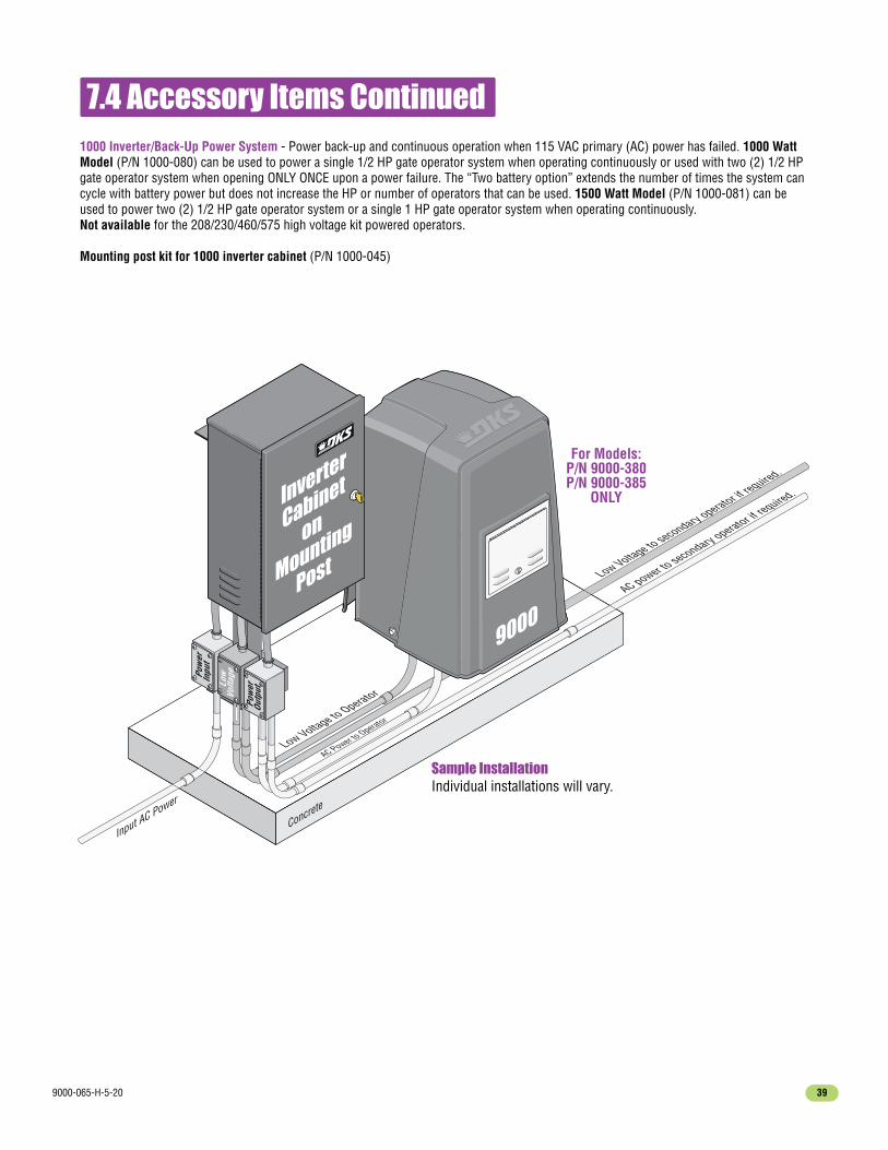
9000-065-H-5-20 39
7.4 Accessory Items Continued
Concrete
Pow
erIn
put
Low Voltage to Operator
Low Voltage to secondary operator if required.
Low
Volta
ge
AC Power to Operator
AC power to secondary operator if
required.
Pow
erOu
tput
Input AC Power
Inverter
Cabinet
on
Mounting
Post
9000
Sample InstallationIndividual installations will vary.
1000 Inverter/Back-Up Power System - Power back-up and continuous operation when 115 VAC primary (AC) power has failed. 1000 Watt Model (P/N 1000-080) can be used to power a single 1/2 HP gate operator system when operating continuously or used with two (2) 1/2 HP gate operator system when opening ONLY ONCE upon a power failure. The “Two battery option” extends the number of times the system can cycle with battery power but does not increase the HP or number of operators that can be used. 1500 Watt Model (P/N 1000-081) can be used to power two (2) 1/2 HP gate operator system or a single 1 HP gate operator system when operating continuously.Not available for the 208/230/460/575 high voltage kit powered operators.
Mounting post kit for 1000 inverter cabinet (P/N 1000-045)
For Models:P/N 9000-380P/N 9000-385
ONLY

9000-065-H-5-2040
REVERSELOOP
P2
EXITLOOP
POWER
NC
TIMEDELAY
NOREV SENSEPRIMARY
4405-018
REV SENSESECONDARY
2
4
5
6
7
8
1 ON
SW2
23
41 O
NSW
1
23
45
67
8
OB
CB
OE
CE
G
G
1
ON 1477-010SW1
2 3 4
1
2
3
4
FIRE
20
19181716
151413
121110
9876
5432
1
Model 9000 1/2 HP or 1 HP 115 VAC PRIMARY Operator
AC PowerConvenience
115 VAC Outlets
Secondary OperatorCurrent Sensor
115 VACNEU HOT
Gray
Gray
Gray
Gray
Red
Black
Black
Black
Black
Blue
Blue
Blue
Red
Red
Red
Orange
Orange
Yellow
Yellow Yellow
Orange
White 1/2 HPBlack 1 HP
White
White
White
White
White
Orange
Orange
Brown
Brown
White
White
Power
Power
Neutral
Brown
Brown
Ground
Ground
ChassisGround
Limit Switch Limit Switch
PUSH TO OPERATE
technician use only
1/2 HP - 2 Turns1 HP - 1 Turn
Remote RadioReceiver Terminal
ChassisGround
Secondary InterfaceTerminal
1/2 HPMotor
or1 HP
Reset
Alarm
White
YellowRed
White Loops

9000-065-H-5-20 41
Model 9000 Secondary Operator
Gray Gray
Gray
Orange
Yellow
Yellow
Orange
White
GroundLimit Switch Limit Switch
Secondary Operator Terminal
1RE
DM
otor
2
BLUE
Mot
or
3
WHI
TENe
utra
l
4
PURP
LE24
VAC
5
YELL
OWLi
mit
6
BROW
NSp
are
7
ORAN
GELi
mit
8
GRAY
COM
Red
White for 1/2 HPBlack for 1 HP
Red
Blue
1/2 HPMotor
or1 HP

9000-065-H-5-2042
Please read SECTION 6 - OPERATING INSTRUCTIONS for more information about operating this gate operator.
A KEY has been supplied that will unlock the control panel cover on this gate operator.
8.1 Alarm Sounding and Gate WILL NOT Operate
When alarm is sounding . . ALWAYS CHECK GATE AREA FOR ANY OBSTRUCTIONS FIRST.
The audio alarm will sound for five minutes, or until the operator’s reset button is pushed. After (5) five minutes the alarm will “chirp every 5 sec.” and the hard shutdown condition will remain in affect until the reset button is pushed.
UNLOCK the control panel cover with KEY and press RESET BUTTON.This will reset the gate operator and allow normal gate operation again.
Note: The owner of the gate operator is responsible for the KEY availability.
SECTION 8 - OWNER OF THE GATE OPERATOR
If the cause of the alarm cannot be corrected, shut-off power andDO NOT place this operator back into service until the malfunction can be identified and CORRECTED.
IMPORTANT: Putting this gate operator back into service without CORRECTING the cause of the alarm could result in serious injury or DEATH!
Gate Operator is in a Hard Shutdown Condition when Alarm is SoundingThis occurs when:1. The inherent entrapment protection system (Type A) gets activated TWO consecutive times before the gate completes the open or close cycle.2. The reversing edge contact sensor (Type B2) gets activated and reverses but before the gate completes the reverse cycle the inherent entrapment protection system (Type A) gets activated.
ACPOWER
PUSH TO
OPERATE
OFF
RESET
ALARM
ACPOWER
TO
ATE
F
MANUAL RELEASE
RESET BUTTON
Control
Panel Cover
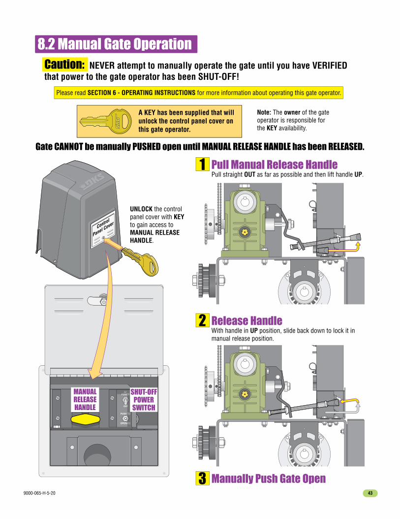
9000-065-H-5-20 43
8.2 Manual Gate OperationCaution: NEVER attempt to manually operate the gate until you have VERIFIED that power to the gate operator has been SHUT-OFF!
Please read SECTION 6 - OPERATING INSTRUCTIONS for more information about operating this gate operator.
Gate CANNOT be manually PUSHED open until MANUAL RELEASE HANDLE has been RELEASED.
A KEY has been supplied that will unlock the control panel cover on this gate operator.
Note: The owner of the gate operator is responsible for the KEY availability.
Control
Panel Cover
ACPOWER
PUSH TO
OPERATE
OFF
ACPOWER
TO
ATE
F
MANUAL RELEASE HANDLE
SHUT-OFFPOWER
SWITCH
Pull Manual Release HandlePull straight OUT as far as possible and then lift handle UP.
1
Release HandleWith handle in UP position, slide back down to lock it in manual release position.
2
Manually Push Gate Open3
UNLOCK the control panel cover with KEY to gain access to MANUAL RELEASE HANDLE.

9000-065-H-5-2044
8.3 Gate Operator’s Monthly Checkup
Caution: Make SURE gate area is clear BEFORE testing the gate operator!
DO NOT repair or adjust gate systems yourself. Contact a trained gate systems technician with any questionsor to make any repairs or adjustments. If you feel uncomfortable performing any of these inspections or testing,a qualified service technician will perform the visual inspections and testing for you.You can find a trained service technician at DoorKing’s “Dealer Locator” at www.doorking.com
Test Built-In Reversing SensorBegin with the gate in the fully OPEN position. Stand just outside the path of the gate and close the gate (typically auto-timer will time-out and close gate automatically). As the gate is closing, firmly press a solid object against the end of the gate frame in the direction opposing the travel of the gate. The gate should stop within 2 sec. and reverse to the OPEN position. Another input command is needed before the gate will reset and close again. Repeat this test while opening the gate. Start from the fully CLOSED position. While opening, gate should stop and reverse to the CLOSE position. If gate does NOT respond like it should in either direction of gate travel, contact a trained service technician to make adjustments or repairs.
Test Photo SensorsIf the gate has a photo sensing device protecting the path of a closing gate, perform the following test. Begin with the gate in the fully OPEN position. Stand just outside the path of the gate and close the gate (typically auto-timer will time-out and close gate automatically). Pass an object across the path of the closing photo sensing beam. The gate should stop within 2 sec. and reverse to the OPEN position. Typically the auto-timer times out and gate closes again.If the gate has a photo sensing device protecting the path of a opening gate, start from the fully CLOSED position. OPEN gate. Pass an object across the path of the opening photo sensing beam. The gate should stop, the gate will resume opening when the beam is clear. If gate does NOT respond like it should in either direction of gate travel, contact a trained service technician to make adjustments or repairs.
Test Reversing EdgesIf the gate has a reversing edge(s) protecting the path of a closing gate, perform the following test. Begin with the gate in the fully OPEN position. Stand just outside the path of the gate and close the gate. As the gate is closing, firmly press a solid object against the reversing edge in the direction opposing the travel of the gate. The gate should stop within 2 sec. and reverse to the OPEN position (typically auto-timer will time-out and close gate automatically). If the gate encounters another obstruction before it is closed, the gate will stop and reverse to the OPEN position again. A input command is needed before the gate will reset and close again, auto-timer will NOT close gate (Typically, press your remote button for input command).If the gate has a reversing edge(s) protecting the path of a opening gate, starting from the fully CLOSED position.Stand just outside the path of the gate and open the gate. OPEN gate. As the gate is opening, firmly press a solid object against the reversing edge in the direction opposing the travel of the gate. gate should stop and reverse to the CLOSE position. If gate does NOT respond like it should in either direction of gate travel, contact a trained service technician to make adjustments or repairs.
Visual InspectionVisually inspect the rollers, fasteners, brackets and other gate hardware for proper alignment, proper tightness, and signs of damage, breakage, looseness, rust or wear. Moving parts should be lubricated and should not be squeaking.Visually inspect wiring for fraying or exposure. If a malfunction is found, contact a trained service technician to make adjustments or repairs.
Note: This gate operator uses high levels of force to move the gate and most people underestimate the power of these systems and do not realize the potential hazards associated with this system if NOT maintained properly.Scheduled maintenance visits are offered by most qualified service technicians to MAINTAIN your gate operator system.

9000-065-H-5-20 45
8.4 New Installation Checklist for Installer and Property Owner
Gate/Hardware: Insure that there is a means to prevent the gate from falling over in the event of a roller or hingefailure. Insure the gate has physical limit stops and that gravity will not initiate motion of the gate. Insure that allrollers are guarded or covered to eliminate the possibility of a finger being inserted between the roller and gate.
The gate operator system is in compliance with the entrapment protection requirements of UL 325. Identify allpotential entrapment zones and ensure they are protected. Potential pinch areas have been guarded so as to beinaccessible OR have a contact (reverse edge) and/or non-contact (photocell) obstruction sensing devices installed.Verify that the system has in place external entrapment protection, independent from the inherent entrapmentprotection. Edge sensors or photocells are typical, other means are possible. For more information see yourspecific installation/owners manual for entrapment protection installation and locations.
Slide Gate: Insure that the maximum opening in the gate and in that portion of the adjacent fence that the gate covers when the gate is in the open position is such that a 2 ¼" sphere cannot pass through the openings up to 72 inches above the ground or to the top of the gate, whichever is less. If the gate and adjacent fence do not meet this requirement, wire mesh (or other means) must be added to meet this requirement before placing the gate system in operation.
Insure that any gaps between the slide gate and stationary posts/pilasters is less than 2 1/4" and that these areas are protected with an entrapment protection device.
Warning signs have been installed so that they are visible from each side of the gate - whether the gate is open or closed.
Instructions: Check the space next to each item (“✓”) to indicate that it has been addressed by installer AND property owner.If it is not applicable, enter N/A. Please note that the checklist is intended to be a summary of many important automated vehicular gate aspects, But may not inclusively identify all potential hazards of every specific gate system installation.
Each item listed and checked has been examined by the Installer and is CLEARLY understood by the Property Owner.
The installer has properly adjusted the inherent entrapment protection feature on the gate operator, and has tested the gate to make sure that the gate stops and reverses a short distance upon striking an immovable object.
The installer has instructed the property owner in the proper use of the gate operator and has reviewed the operational functions, obstruction-sensing devices, alarm, and reset as outlined in your specific installation/owners manual.
The installer has instructed the property owner in the proper use of the operator's manual release feature as outlined in your specific installation/owners manual.
The installer has explained to the property owner that a regular maintenance schedule for both the gate and the gate operator is recommended, including regular testing of entrapment protection as outlined in the manufacturer's instructions.
The installer has reviewed all safety instructions with the property owner, including the need to never let children operate or play with gate controls, to keep the remote control away from children, and to always keep people and objects away from the gate.
The installer has left the installation/owners manual with the property owner for future reference.
InstallerPropertyOwner Description
Check that placement of user operational controls are six (6) or more feet away from the gate. If any operational control is closer than six (6) feet to the gate, DO NOT place the automated vehicular gate into service.
The operator is installed on a gate used for vehicles only. Verify that separate pedestrian access is provided oravailable, and the access is such that pedestrians cannot come in contact with the moving vehicular access gateduring its entire length of travel.

9000-065-H-5-2046

ww
w.doorking.com
to get a PDF of this manual - Rem
ove this page OR print this page in color, fold and laminate - Place at the gate operator
Manual Gate Operation
Please read SECTION 6 - OPERATING INSTRUCTIONS for more inform
ation about operating this gate operator.
When alarm
is sounding . . ALWAYS CHECK GATE AREA FOR ANY OBSTRUCTIONS FIRST.
The audio alarm w
ill sound for five minutes, or until the operator’s reset button is pushed. After (5) five m
inutes the alarm
will “chirp every 5 sec.” and the hard shutdow
n condition will rem
ain in affect until the reset button is pushed.
Gate Operator is in a Hard Shutdown Condition w
hen Alarm is Sounding
This occurs when:
1. The inherent entrapment protection system
(Type A) gets activated TWO consecutive tim
es before the gate completes
the open or close cycle.
2. The reversing edge contact sensor (Type B2) gets activated and reverses but before the gate completes the reverse
cycle the inherent entrapm
ent protection system (Type A) gets activated.
If the cause of the alarm cannot be corrected, shut-off pow
er andDO NOT place this operator back into service until the m
alfunction can be identified and CORRECTED.
IMPORTANT: Putting this gate operator back into service w
ithout CORRECTING the cause of the alarm
could result in serious injury or DEATH!
Caution: NEVER attempt to m
anually operate the gate until you have VERIFIED that pow
er to the gate operator has been SHUT-OFF!
Please read SECTION 6 - OPERATING INSTRUCTIONS for more inform
ation about operating this gate operator.
Alarm Sounding and Gate W
ILL NOT Operate
A KEY has been supplied that w
ill unlock the control panel cover on this gate operator.
Name
Phone #
To obtain key to unlockgate operator contact:
A KEY has been supplied that w
ill unlock the control panel cover on this gate operator.
Name
Phone #
To obtain key to unlockgate operator contact:
UNLOCK the control panel cover with KEY and press RESET BUTTON.
This will reset the gate operator and allow
normal gate operation again.
ACP
OW
ER
RESET
ALARM
ACP
OW
ER
MAN
UAL R
ELE
ASE
RESET BUTTON
Control
Panel Cover
Gate CANNOT be manually PUSHED open until M
ANUAL RELEASE HANDLE has been RELEASED.
Control
Panel Cover
ACP
OW
ER
PU
SH
TO
OP
ER
ATE
OFF
ACP
OW
ERTO
ATE
F
MANUAL
RELEASE HANDLE
SHUT-OFFPOW
ERSW
ITCH
Pull Manual Release Handle
Pull straight OUT as far as possible and then lift handle UP.1
Release HandleW
ith handle in UP position, slide back down to lock it in
manual release position.
2
Manually Push Gate Open
3
UNLOCK the control panel cover w
ith KEY to gain access to M
ANUAL RELEASE HANDLE.

Installation/Owner’s Manual Series 9000Series 9000Series 9000
Copyright 2009 DoorKing, Inc. All rights reserved.
Use this manual for circuit board 4405-018 Revision A or higher.
www.doorking.com
Vehicular Slide Gate Operator
DoorKing, Inc.120 S. Glasgow Avenue
Inglewood, California 90301U.S.A.
Phone: 310-645-0023Fax: 310-641-1586
Entrapment Protection must be provided for the gate system where the risk of entrapment or obstruction exists. The operator will NOT run without one or more monitored type B1 or B2 entrapment protection devices in EACH direction of gate travel.
UL 325 August 2018 Standard
THIS PRODUCT IS TO BE INSTALLED AND SERVICED BY A TRAINED GATE/DOOR SYSTEMS TECHNICIAN ONLY. Visit www.doorking.com/dealer-locator to find a professional installing and servicing dealer in your area.
9000-065-H-5-20