INSTALLATION,OPERATION,AND MAINTENANCE MANUAL MODEL IRA ... · The Welker IRA-4SS Automatic...
27
INSTALLATION, OPERATION, AND MAINTENANCE MANUAL WELKER AUTOMATIC INSERTION PROBE REGULATOR MODEL IRA-4SS DRAWING NUMBER AD172DF MANUAL NUMBER IOM-026 REVISION Rev. J, 8/17/2017
Transcript of INSTALLATION,OPERATION,AND MAINTENANCE MANUAL MODEL IRA ... · The Welker IRA-4SS Automatic...

INSTALLATION, OPERATION, AND MAINTENANCE MANUAL
WELKER AUTOMATIC INSERTION PROBE REGULATOR
MODELIRA-4SS DRAWING NUMBERAD172DF MANUAL NUMBERIOM-026 REVISIONRev. J, 8/17/2017

TABLE OF CONTENTS
2 IOM-026 MODEL: IRA-4SS REV: J 13839 West Bellfort Street, Sugar Land, TX 77498 welker.com Service Department 281.491.2331
Copyright © 2017 Welker, Inc. All rights reserved. Welker®, W Welker®, W logo, WelkerScope®, Welker Jet®, and OdorEyes® are registered trademarks of Welker, Inc.
SAFETY 3
1. PRODUCT INFORMATION 4
1.1 Introduction 4
1.2 Product Description 4
1.3 Important Information 4
1.4 Specifications 5
1.5 Equipment Diagram 6
2. INSTALLATION & OPERATION 7
2.1 Before You Begin 7
2.2 Preparing the IRA-4SS for Installation 7
2.3 Installing the IRA-4SS 10
2.4 Retracting the IRA-4SS 12
3. MAINTENANCE 15
3.1 Before You Begin 15
3.2 Maintenance 16
3.3 Troubleshooting 24
APPENDIX 26
A: Referenced or Attached Documents 26

IMPORTANT SAFETY INFORMATIONREAD ALL INSTRUCTIONS
Notes emphasize information and/or provide additional information to assist the user.
Caution messages appear before procedures that could result in damage to equipment if not observed.
Warning messages appear before procedures that could result in personal injury if not observed.
This manual is intended to be used as a basic installation and operation guide for the Welker Automatic Insertion Probe Regulator, IRA-4SS. For comprehensive instructions, please refer to the IOM Manuals for each individual component. A list of relevant component IOM Manuals is provided in Appendix A of this manual.
The information in this manual has been carefully checked for accuracy and is intended to be used as a guide for the installation, operation, and maintenance of the Welker equipment described in this manual. Correct installation and operation, however, are the responsibility of the end user. Welker reserves the right to make changes to this manual and all products in order to improve performance and reliability.
BEFORE YOU BEGIN
Read these instructions completely and carefully.
IMPORTANT - Save these instructions for local inspector's use.
IMPORTANT - Observe all governing codes and ordinances.
Note to Installer - Leave these instructions with the end user.
Note to End User - Keep these instructions for future reference.
Installation of this Automatic Insertion Probe Regulator is of a mechanical nature.
Proper installation is the responsibility of the installer. Product failure due to improper installation is not covered under the warranty.
If you received a damaged Automatic Insertion Probe Regulator, please contact a Welker representative immediately.
Phone: 281.491.2331Address: 13839 West Bellfort Street
Sugar Land, TX 77498
SAFETY
3 IOM-026 MODEL: IRA-4SS REV: J 13839 West Bellfort Street, Sugar Land, TX 77498 welker.com Service Department 281.491.2331

1.1 Introduction
We appreciate your business and your choice of Welker products. The installation, operation, and maintenance liability for this equipment becomes that of the purchaser at the time of receipt. Reading the applicable Installation, Operation, and Maintenance (IOM) Manuals prior to installation and operation of this equipment is required for a full understanding of its application and performance prior to use.*
If you have any questions, please call Welker at 1-281-491-2331.
*The following procedures have been written for use with standard Welker parts and equipment. Assemblies that have been modified may have additional
requirements and specifications that are not listed in this manual.
1.2 Product Description
The Welker IRA-4SS Automatic Insertion Probe Regulator is designed to provide an analyzer with a sample stream at an output pressure adequate for downstream instrumentation. The sample stream is regulated at the probe tip to minimize line pack and sample retention, allowing the regulated sample stream to reach the analyzer more quickly. The thermal fins mitigate the cooling brought on by the Joule-Thomson effect.
When used with a pipeline isolation valve, the IRA-4SS can be safely inserted and retracted without interrupting the flow or operation of the pressurized pipeline. Insertion lengths can be set with the adjustable lock collar, making the IRA-4SS compatible with multiple pipe sizes.
Welker may custom design the IRA-4SS to suit the particular application and specifications of each customer.
1.3 Important Information
1. The unit should always be mounted to a full port pipeline isolation valve with a bore that exceeds the probe diameter. 2. Oil Reservoir: With the use of a hydraulic oil reservoir, process or auxiliary pressure is applied and released to ensure
smooth insertion and retraction of the shaft. Welker ships the oil reservoir with the necessary oil volume and standard
vertical installation. For horizontally-mounted probes, the oil reservoir must be positioned so that it remains vertical
while inserted. The oil reservoir will not function properly if installed horizontally. The oil reservoir can be
positioned at the factory to suit the particular application and specifications of each customer if noted at the time of
order. As necessary, see Section 2.2, Preparing the IRA-4SS for Installation, for instructions on rotating the oil reservoir.
For products containing liquid, sand, or other abrasive contaminants, Welker recommends the use of an auxiliary gas supply
(e.g., clean, dry nitrogen gas) to prevent damage to the insertion cylinder and oil reservoir.
SECTION 1: PRODUCT INFORMATION
4 IOM-026 MODEL: IRA-4SS REV: J 13839 West Bellfort Street, Sugar Land, TX 77498 welker.com Service Department 281.491.2331

1.4 Specifications
The specifications listed in this section are generalized for this equipment. Welker can modify the equipment according to your
company's needs. Please note that the specifications may vary depending on the customization of your equipment.
Table 1: IRA-4SS Specifications
Products Sampled Natural Gas and Natural Gas Liquids Compatible With the Materials of Construction
Materials of Construction 316/316L Stainless Steel, PTFE, Teflon®, and Viton®Others Available
Maximum Allowable Operating Pressure 2160 psig @ -20 °F to 120 °F (148 barg @ -28 °C to 48 °C)Others Available
Pipeline Connection
NPT¾" MNPT (Standard)1" MNPT1½" MNPT2" MNPT
FlangedSize: 1", 1½", 2", or 3"Rating: 150, 300, 600, and 900 ANSI
Output Ranges0–25 psig (0–1.7 barg)0–50 psig (0–3.4 barg)20–100 psig (1.3–6.8 barg)
Insertion Lengths
0–12" (0–30 cm) (Standard)0–18" (0–45 cm) (Standard)0–24" (0–60 cm)0–30" (0–76 cm)0–36" (0–91 cm)Others Available
Insertion Diameters½"³⁄₈"⁵⁄₈" (Standard)
Operation Diaphragm-Operated Regulator
Mounting Vertical (Standard)Horizontal
Features Hydraulic Oil ReservoirOutlet Pressure Gauge and Relief (Standard)
Industry Standards and Product Certifications
API 14.1 (Standard)GPA 2166 (Standard)ISO 10715 (Standard)CE CertificationCRN Certification
OptionsInsulation BlanketProbe TipNACE Compliance
5 IOM-026 MODEL: IRA-4SS REV: J 13839 West Bellfort Street, Sugar Land, TX 77498 welker.com Service Department 281.491.2331

1.5 Equipment Diagram
Figure 1: IRA-4SS Diagram
6 IOM-026 MODEL: IRA-4SS REV: J 13839 West Bellfort Street, Sugar Land, TX 77498 welker.com Service Department 281.491.2331

2.1 Before You Begin
After unpacking the unit, check the equipment for compliance and any damage that may have occurred during shipment.
Immediately contact a Welker representative if you received damaged equipment.
When sealing fittings with PTFE tape, refer to the proper sealing instructions for the brand used.
1. A sample probe is recommended to extract sample from the center one-third (¹⁄₃) of the pipeline in a location where
the product is well-mixed and will yield an accurate and representative sample. 2. Welker recommends that the unit be installed in the top of the pipe. 3. Handle the unit with care. Avoid bending and scratching the insertion shaft, which has a polished surface that travels
through seals. 4. Operate the unit slowly and smoothly while inserting and retracting to avoid damaging the unit. 5. Take care not to close the pipeline isolation valve on the insertion shaft while the shaft is inserted in the pipeline. This is
the most common cause of damage to Welker probes.
2.2 Preparing the IRA-4SS for Installation
1. As necessary, install a pressure gauge to the pressure gauge port (Figure 2).
Figure 2: Port Diagram
Welker can install a relief valve and pressure gauge if requested at the time of order.
SECTION 2: INSTALLATION & OPERATION
7 IOM-026 MODEL: IRA-4SS REV: J 13839 West Bellfort Street, Sugar Land, TX 77498 welker.com Service Department 281.491.2331

2. As necessary, use a safe auxiliary gas supply to set the relief valve to the proper pressure. Refer to the Installation,
Operation, and Maintenance (IOM) Manual for the relief valve for instructions on setting the relief.
A downstream relief is required.
If a Welker Relief Valve is used, Welker can set the relief valve prior to shipment if requested at the time of order.
3. As necessary, install the set relief valve to the relief valve port (Figure 2).
Determining Insertion Depth
4. Prior to installation, the distance the insertion shaft will need to travel inside the pipeline must be determined. Measure the distance the shaft must travel from the top of the pipeline isolation valve to the desired insertion depth (e.g., the center one-third (¹⁄₃) of the pipeline) (Figure 3). This will be the shaft insertion length.
Figure 3: Determining the Insertion Depth
5. Pull up on the insertion shaft to ensure that it is fully retracted. The end of the insertion shaft should be flush with or in
close proximity to the bottom face of the lower housing.
The oil reservoir may need to be relieved of pressure to fully retract the insertion shaft. To relieve pressure in the oil reservoir, open
insertion/retraction valve A and vent/relief valve B.
6. Beginning at the top of the standoff, measure along the insertion shaft to the desired insertion length. As necessary, use
a felt tip pen to mark this point.
8 IOM-026 MODEL: IRA-4SS REV: J 13839 West Bellfort Street, Sugar Land, TX 77498 welker.com Service Department 281.491.2331

Positioning the Lock Collar
7.
Figure 4: Positioning the Lock Collar
Remove the lockdown bolt from the top of the lock collar.
8. Loosen the cap screw on the side of the lock collar.
9. Carefully slide the lock collar along the insertion shaft to the desired insertion length, taking care not to scratch the insertion shaft (Figure 4).
10. Tighten the cap screw on the side of the lock collar to secure the lock collar to the insertion shaft at the marked point
(Figure 4).
This procedure ensures that the insertion length will be mechanically limited by the lock collar.
11. If the oil reservoir needs to be rotated, continue to step 12. If the oil reservoir does not need to be rotated, proceed to
Section 2.3, Installing the IRA-4SS.
Rotating the Oil Reservoir (As Necessary)
For horizontally-mounted probes, the oil reservoir must be positioned so that it remains vertical while inserted. The oil reservoir
will not function properly if oriented horizontally.
12. Detach the tubing between isolation valves C and D.
13. Unscrew and remove the oil reservoir clamp from the insertion cylinder and oil reservoir.
14. Loosen insertion/retraction valve A at the top cap.
15. Reposition the oil reservoir so that it is perpendicular to the insertion cylinder. Isolation valve C on the oil reservoir should point down.
16. Tighten insertion/retraction valve A at the top cap.
17. Measure a new piece of tubing to connect isolation valve C to isolation valve D.
18. Attach nuts and ferrules to the ends of the new tubing.
19. Using the new tubing, connect isolation valve C to isolation valve D.
9 IOM-026 MODEL: IRA-4SS REV: J 13839 West Bellfort Street, Sugar Land, TX 77498 welker.com Service Department 281.491.2331

2.3 Installing the IRA-4SS
Ensure that the operating pressure of the pipeline does not exceed the maximum allowable operating pressure of the unit.
For long probes installed horizontally, Welker recommends field installation of bracing support for the outlet end of the probe
to offset the cantilever effect and prevent bending of the shaft. Any bracing or support installed should NOT contact the probe
shaft, as scratching or other damage to the shaft may lead to loss of integrity of the sealing surface.
Installation procedures apply to vertical and horizontal installation. Note that Welker recommends vertical installation.
If the unit will be inserted using an auxiliary gas, continue to step 1.
If the unit will be inserted using pipeline product, proceed to step 17.
Using an Auxiliary Gas (Optional)
An auxiliary gas supply is OPTIONAL for this unit. However, for products containing liquid, sand, or other abrasive contaminants,
Welker strongly recommends the use of an auxiliary gas (e.g., clean, dry nitrogen gas) to prevent damage to the insertion
cylinder.
1. Ensure that all valves on the unit are closed.
2. Detach the tubing between isolation valves C and D (Figure 1).
3. Plug isolation valve D.
4. Connect a customer-supplied auxiliary gas supply to isolation valve C.
5. Install the unit to the pipeline isolation valve.
6. Connect vent/relief valve B to a customer-supplied recovery system (Figure 1). Valve B should remain closed.
7. In a counterclockwise direction, back off the adjusting screw on the regulator subassembly (Figure 5) so that the unit is
closed (i.e., no setting or tension on the spring).
Figure 5: Outlet Pressure Adjustment
10 IOM-026 MODEL: IRA-4SS REV: J 13839 West Bellfort Street, Sugar Land, TX 77498 welker.com Service Department 281.491.2331
8. Slowly open the pipeline isolation valve. Check for leaks and repair as necessary.
9. Check the outlet pressure gauge on the IRA-4SS. The gauge should read zero (0) psig. If the pressure gauge does not read zero (0) psig, close the pipeline isolation valve, and then disassemble the IRA-4SS and check for internal leaking, making sure to examine the poppet and seat retainer in the thermal fin subassembly for damage. See Section 3.2, Maintenance, for instructions on disassembling and maintaining the thermal fin subassembly.
10. Open the valve on the customer-supplied auxiliary gas supply and regulate the supply to pipeline pressure.
11. With insertion/retraction valve A open and vent/relief valve B closed, slowly open isolation valve C. The insertion shaft
will begin to insert into the pipeline.
Once the insertion shaft begins to insert, do not open the valve any further. The insertion shaft should be inserted slowly and
smoothly. Opening the valve too quickly or too much may cause the insertion shaft to insert into the pipeline too quickly and
may result in damage to the unit.
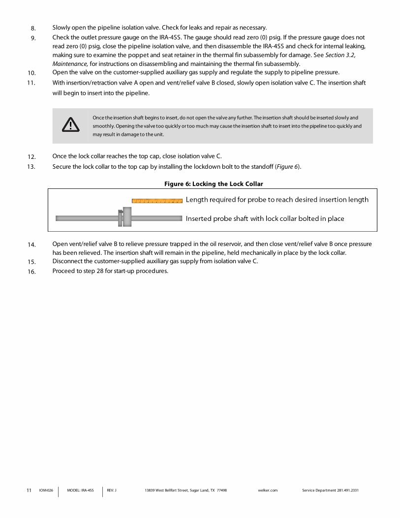
12. Once the lock collar reaches the top cap, close isolation valve C.
13. Secure the lock collar to the top cap by installing the lockdown bolt to the standoff (Figure 6).
Figure 6: Locking the Lock Collar
14. Open vent/relief valve B to relieve pressure trapped in the oil reservoir, and then close vent/relief valve B once pressure
has been relieved. The insertion shaft will remain in the pipeline, held mechanically in place by the lock collar. 15. Disconnect the customer-supplied auxiliary gas supply from isolation valve C.
16. Proceed to step 28 for start-up procedures.
11 IOM-026 MODEL: IRA-4SS REV: J 13839 West Bellfort Street, Sugar Land, TX 77498 welker.com Service Department 281.491.2331

Using Pipeline Product (If Not Using an Auxiliary Gas)
17. Ensure that all valves on the unit are closed.
18. Install the unit to the pipeline isolation valve.
19. In a counterclockwise direction, back off the adjusting screw on the regulator subassembly (Figure 5) so that the unit is closed (i.e., no setting or tension on the spring).
20. Connect vent/relief valve B to a customer-supplied recovery system (Figure 1). Valve B should remain closed.
21. Slowly open the pipeline isolation valve. Check for leaks and repair as necessary.
22. Check the outlet pressure gauge on the IRA-4SS. The gauge should read zero (0) psig. If the pressure gauge does not read zero (0) psig, close the pipeline isolation valve, and then disassemble the IRA-4SS and check for internal leaking, making sure to examine the poppet and seat retainer in the thermal fin subassembly for damage. See Section 3.2, Maintenance, for instructions on disassembling and maintaining the thermal fin subassembly.
23. Slowly open isolation valves C and D to allow pipeline pressure to enter the oil reservoir.
24. Slowly open insertion/retraction valve A. The insertion shaft will begin to insert into the pipeline.
Once the insertion shaft begins to insert, do not open the valve any further. The insertion shaft should be inserted slowly and
smoothly. Opening the valve too quickly or too much may cause the insertion shaft to insert into the pipeline too quickly and
may result in damage to the unit.
25. Once the lock collar reaches the top cap, close isolation valves C and D.
26. Secure the lock collar to the top cap by installing the lockdown bolt to the standoff (Figure 6).
27. Open vent/relief valve B to relieve pressure trapped in the oil reservoir, and then close vent/relief valve B once pressure has been relieved. The insertion shaft will remain in the pipeline, held in place mechanically by the lock collar.
Start-Up Procedures
28. Install customer-supplied tubing or other fittings to the outlet port of the IRA-4SS (Figure 2).
29. Loosen the jam nut on the adjusting screw (Figure 5).
30. Screw the adjusting screw clockwise to adjust the outlet pressure. Tighten the jam nut on the adjusting screw to secure the adjusting screw at the desired outlet pressure (Figure 5).
2.4 Retracting the IRA-4SS
1. Ensure that all valves on the unit are closed.
2. Ensure that vent/relief valve B is connected to a customer-supplied recovery system. Valve B should remain closed.
3. Disconnect the customer-supplied tubing, fittings, or instrument attached to the unit.
If the unit will be retracted using an auxiliary gas, continue to step 4.
If the unit will be retracted using pipeline product, proceed to step 17.
12 IOM-026 MODEL: IRA-4SS REV: J 13839 West Bellfort Street, Sugar Land, TX 77498 welker.com Service Department 281.491.2331

Using an Auxiliary Gas (Optional)
An auxiliary gas supply is OPTIONAL for this unit. However, for products containing liquid, sand, or other abrasive contaminants,
Welker strongly recommends the use of an auxiliary gas (e.g., clean, dry nitrogen gas) to prevent damage to the insertion
cylinder.
4. Ensure that the tubing between isolation valves C and D is detached.
5. Ensure that isolation valve D is plugged.
6. Connect a customer-supplied auxiliary gas supply to isolation valve C.
7. Open the valve on the customer-supplied auxiliary gas supply and regulate the supply to pipeline pressure.
8. Open insertion/retraction valve A, and then slowly open isolation valve C to ensure that auxiliary pressure is applied to
the internal shaft piston.
Failure to ensure that adequate pressure is applied to the internal shaft piston prior to retraction could result in unexpected
retraction of the insertion shaft, which could damage the unit or injure the operator.
9. Close isolation valve C.
10. Remove the lockdown bolt from the standoff.
11. Slowly open vent/relief valve B. This will relieve pressure from the internal shaft piston, allowing the insertion shaft to
begin retracting from the pipeline. If pipeline pressure is not sufficient to push the insertion shaft out of the line, the
insertion shaft may be retracted manually.
Once the insertion shaft begins to retract, do not open the valve any further. The insertion shaft should be retracted slowly and
smoothly. Opening the valve too quickly or too much may cause the insertion shaft to retract from the pipeline too quickly and
may result in damage to the unit.
If the insertion shaft will not retract from the pipeline automatically or manually, the insertion shaft could be bent or damaged.
Contact Welker for service options.
12. Once the insertion shaft has been fully retracted from the pipeline, close vent/relief valve B, and then close the pipeline
isolation valve to isolate the unit from pressure. 13. Disconnect the customer-supplied auxiliary gas supply from isolation valve C.
14. If complete removal of the unit from the pipeline is desired, remove the plug from isolation valve D, and then open isolation valve D to relieve any trapped pressure.
15. Disconnect the customer-supplied recovery system from vent/relief valve B. The unit is now ready to be removed from
the pipeline isolation valve for maintenance or to be relocated.
Continuous pressure venting from one or more of the unit's valves may indicate leakage from the pipeline isolation valve. The
operator should consult an on-site safety engineer.
16. If the unit will remain secured to the pipeline after retraction, secure the lock collar to the top cap by repositioning the
lock collar and tightening the lockdown bolt in the standoff.
13 IOM-026 MODEL: IRA-4SS REV: J 13839 West Bellfort Street, Sugar Land, TX 77498 welker.com Service Department 281.491.2331

Using Pipeline Product (If Not Using an Auxiliary Gas)
17. Open insertion/retraction valve A, and then slightly open isolation valves C and D to ensure that pipeline pressure is
applied to the internal shaft piston.
Failure to ensure that adequate pressure is applied to the internal shaft piston prior to retraction could result in unexpected
retraction of the insertion shaft, which could damage the unit or injure the operator.
18. Close isolation valves C and D.
19. Remove the lockdown bolt from the standoff.
20. Slowly open vent/relief valve B. This will relieve pipeline pressure from the internal shaft piston, allowing the insertion
shaft to begin retracting from the pipeline. If pipeline pressure is not sufficient to push the insertion shaft out of the line,
the insertion shaft may be retracted manually.
Once the insertion shaft begins to retract, do not open the valve any further. The insertion shaft should be retracted slowly and
smoothly. Opening the valve too quickly or too much may cause the insertion shaft to retract from the pipeline too quickly and
may result in damage to the unit.
If the insertion shaft will not retract from the pipeline automatically or manually, the insertion shaft could be bent or damaged.
Contact Welker for service options.
21. Once the insertion shaft has been fully retracted from the pipeline, close vent/relief valve B, and then close the pipeline
isolation valve to isolate the unit from pressure. 22. If complete removal of the unit from the pipeline is desired, open isolation valves C and D to relieve any trapped
pressure, and then ensure that the customer-supplied recovery system has been disconnected from vent/relief valve B.
The unit is now ready to be removed from the pipeline isolation valve for maintenance or to be relocated.
Continuous pressure venting from one or more of the unit's valves may indicate leakage from the pipeline isolation valve. The
operator should consult an on-site safety engineer.
23. If the unit will remain secured to the pipeline after retraction, secure the lock collar to the top cap by repositioning the
lock collar and tightening the lockdown bolt in the standoff.
14 IOM-026 MODEL: IRA-4SS REV: J 13839 West Bellfort Street, Sugar Land, TX 77498 welker.com Service Department 281.491.2331

3.1 Before You Begin
1. Welker recommends that the unit have standard maintenance every six (6) months under normal
operating conditions. In cases of severe service, dirty conditions, excessive usage, or other unique applications that
may lead to excess wear on the unit, a more frequent maintenance schedule may be appropriate. 2. Prior to maintenance or disassembly of the unit, it is advisable to have a repair kit available for repairs of the system in
case of unexpected wear or faulty seals.
New seals supplied in spare parts kits should be lightly lubricated before being installed to ease the installation of the seals and
reduce the risk of damage when positioning them on parts. Wipe excess lubricant from the seals, as it may adversely affect
analytical instrument results.
For sample-exposed seals, Welker recommends non-hydrocarbon-based lubricants, such as Krytox®.
For non-sample-exposed seals, Welker recommends either non-hydrocarbon-based lubricants or silicone-based lubricants, such
as Molykote® 111.
After the seals are installed, the outer diameter of shafts and inner diameter of cylinders may be lubricated to allow smooth
transition of parts.
3. All maintenance and cleaning of the unit should be performed on a smooth, clean surface. 4. Welker recommends having the following tools available for maintenance. Please note that the exact tools required may
vary by model. a. Crescent Wrench (Qty. 2) b. Hex Key Set c. Phillips Head Screwdriver d. Seal Pick e. Tubing Crimp and Accessories
SECTION 3: MAINTENANCE
15 IOM-026 MODEL: IRA-4SS REV: J 13839 West Bellfort Street, Sugar Land, TX 77498 welker.com Service Department 281.491.2331

16 IOM-026 MODEL: IRA-4SS REV: J 13839 West Bellfort Street, Sugar Land, TX 77498 welker.com Service Department 281.491.2331
3.2 Maintenance
1. Prior to maintenance, the unit must be removed from the pipeline. See Section 2.4, Retracting the IRA-4SS, for
instructions on retracting the insertion shaft and removing the unit from the pipeline. 2. Once the unit is removed from the pipeline, ensure that all valves are closed.
Removing the Oil Reservoir
3. Disconnect the tubing between isolation valves C and D. 4. Unscrew the oil reservoir clamp from around the insertion cylinder, taking care not to misplace the nut and screw. 5. Disconnect the oil reservoir from the top cap at insertion/retraction valve A. Valves A, B, and C should remain connected
to the oil reservoir. 6. Verify that the oil reservoir is three-quarters (¾) full. 7. As necessary, remove vent/relief valve B, and then add oil to the oil reservoir. Install vent/relief valve B to the oil
reservoir after oil has been added.
If oil needs to be added to the oil reservoir, this could indicate a leak.
8. Set the oil reservoir aside.

17 IOM-026 MODEL: IRA-4SS REV: J 13839 West Bellfort Street, Sugar Land, TX 77498 welker.com Service Department 281.491.2331
Thermal Fin Subassembly Maintenance
9. Push the insertion shaft through the lower housing so that the thermal fins are fully exposed. 10. Remove the thermal fin subassembly. 11. When the thermal fin subassembly is removed, the contact rod and push rod should easily slide out (Figure 8). As
necessary, gently tilt the unit back and forth until both pieces slide out, taking care not to misplace the small contact
rod.
If the small contact rod is misplaced, a replacement contact rod is required. Contact Welker for a replacement contact rod. Note
that the replacement contact rod may require field modification so that it extends approximately ¹⁄₈" from the regulator body
to contact the diaphragm or piston. If field modification is performed, the edges of the contact rod should be smoothed using a
file or sandpaper. The trimmed and smoothed end of the replacement contact rod should be placed into the push rod during
reassembly.
Figure 7: Thermal Fin Subassembly Diagram
12. While holding the thermal fin subassembly with a crescent wrench, use a second crescent wrench to unscrew the seat
retainer. 13. Remove the spring and poppet. 14. Examine the seating face of the poppet for scratches or damage. Replace as necessary.
Debris or scratches on the poppet will prevent positive shutoff of the regulator.
15. Use a small pointed instrument to carefully remove the seat from the thermal fin subassembly. 16. Inspect the seat for debris or scratches. Replace as necessary.
Debris or scratches on the seat will prevent positive shutoff of the regulator.
17. Replace the O-ring on the seat retainer.

18 IOM-026 MODEL: IRA-4SS REV: J 13839 West Bellfort Street, Sugar Land, TX 77498 welker.com Service Department 281.491.2331
18. Use solvent to clean the screen in the seat retainer.
Welker recommends using a solvent, such as rubbing alcohol, that does not leave a film when dry and will not adversely affect
analytical instrument results.
19. Install the seat to the thermal fin subassembly. 20. Guide the poppet into the seat. 21. Return the spring to the poppet. 22. Return the seat retainer to the thermal fin subassembly and tighten firmly. 23. Replace the O-ring at the base of the thermal fin subassembly, and then set the thermal fin subassembly aside.
Regulator Body Maintenance
Figure 8: Regulator Body and Base
24. Remove the regulator subassembly from the base and set the regulator subassembly aside. 25. Remove the base from the insertion shaft. 26. Replace the O-rings on the base. 27. Install the base to the regulator subassembly and tighten firmly.

19 IOM-026 MODEL: IRA-4SS REV: J 13839 West Bellfort Street, Sugar Land, TX 77498 welker.com Service Department 281.491.2331
Regulator Upper Housing Maintenance
Figure 9: Regulator Maintenance Diagram
28. Loosen the jam nut on the adjusting screw. 29. In a counterclockwise direction, back off the adjusting screw to relieve tension on the spring. 30. As necessary, perform maintenance on the relief valve. Refer to the Installation, Operation, and Maintenance (IOM)
Manual for the relief valve for maintenance instructions. 31. Separate the spring housing from the regulator body. 32. Remove the spring guides and spring. 33. Remove the diaphragm assembly. 34. Inspect the diaphragm for wear. Replace as necessary. 35. Place the diaphragm assembly on top of the regulator body with the bottom spring guide facing up. 36. Place the spring on the diaphragm assembly. Ensure that the spring is sitting on the bottom spring guide. 37. Return the spring guide to the top of the spring. 38. Install the spring housing to the regulator body.
When reassembling the upper housing, HAND TIGHTEN ONLY.

20 IOM-026 MODEL: IRA-4SS REV: J 13839 West Bellfort Street, Sugar Land, TX 77498 welker.com Service Department 281.491.2331
Top Cap and Lower Housing Maintenance
Figure 10: Top Cap Detail
39. Loosen and remove the lock collar from the insertion shaft. 40. Remove the tie bolt nuts and standoff, and then slide the top cap off the shaft. 41. Replace the O-rings and back ups on the top cap.
Figure 11: Lower Housing Detail
42. Carefully slide the insertion shaft out of and the insertion cylinder off the lower housing. 43. Replace the O-rings and back ups on the lower housing.

21 IOM-026 MODEL: IRA-4SS REV: J 13839 West Bellfort Street, Sugar Land, TX 77498 welker.com Service Department 281.491.2331
Shaft and Cylinder Maintenance
Figure 12: Shaft Detail
44. Remove the insertion shaft from the insertion cylinder. 45. Replace the O-ring and back ups on the piston. 46. Closely inspect the polished outer diameter of the insertion shaft. Scratches or pits may cause the seals to leak. If
scratches or pits are present, the unit may need to be repaired or replaced. Contact Welker for service options. 47. Closely inspect the honed inner diameter of the insertion cylinder for scratches or damage. Scratches or pits may cause
the seals to leak. If scratches or pits are present, the unit may need to be repaired or replaced. Contact Welker for
service options.

22 IOM-026 MODEL: IRA-4SS REV: J 13839 West Bellfort Street, Sugar Land, TX 77498 welker.com Service Department 281.491.2331
Reassembly
48. Coat the inside of the top end of the insertion cylinder with lubricant, and then insert the shorter end of the insertion
shaft approximately halfway into the insertion cylinder. The bottom of the insertion cylinder can be identified by its
vent hole. 49. Liberally lubricate the insertion shaft. 50. Carefully slide the bottom of the insertion shaft into the lower housing. 51. Carefully slide the insertion cylinder onto the lower housing. 52. Carefully slide the top cap onto the top end of the insertion shaft and down to the insertion cylinder. 53. Following a cross-bolting sequence, install the tie bolts and tighten the hex nuts to the appropriate torque (Figure 13
and Table 2).
Figure 13: Cross-Bolting Sequence
Table 2: Torque Specifications for Tie Bolts
Tie Bolt Diameter Foot-Pounds (ft•lb) Kilograms per Meter (kg/m)
³⁄₈" 5–6 0.69–0.82
½" 15–20 2.07–2.76
⁵⁄₈" 25–30 3.45–4.14
⁷⁄₈" or 1" 55–65 7.60–8.98
54. Install the standoff to the top cap. 55. Install the lock collar to the top of the insertion shaft. 56. Move the insertion shaft up and down in the insertion cylinder. If the shaft does not move smoothly, check for damage
or incorrect installation. Continuous wear on the insertion shaft may damage the surface finish. 57. Install the thermal fin subassembly to the insertion shaft and tighten firmly. 58. Carefully slide the push rod into the insertion shaft until it slips onto the poppet (Figure 7).
The push rod should fit easily over the poppet and should not stack on top of the poppet. The IRA-4SS will not be able to be
reassembled correctly if the push rod is stacked on top of the poppet.
59. Insert the contact rod into the push rod, and then carefully screw the regulator subassembly with the base into the top
of the insertion shaft (Figure 8). The unit should screw on easily.

23 IOM-026 MODEL: IRA-4SS REV: J 13839 West Bellfort Street, Sugar Land, TX 77498 welker.com Service Department 281.491.2331
If the unit does not screw on easily, loosen the unit slightly, and then gently move the unit back and forth until the contact rod
slips into the regulator body hole.
60. Fully retract the insertion shaft. 61. Prepare the oil reservoir for reattachment by wrapping the valve threads with PTFE tape or coating them with pipe
dope. 62. If pipeline pressure will be used to install the unit to the pipeline, reconnect the tubing between isolation valves C and
D. 63. Reconnect the oil reservoir to the top cap at insertion/retraction valve A. 64. Attach the oil reservoir to the unit. Mount the bracket around the insertion cylinder and secure it with the nut and screw. 65. The unit is now ready for installation. See Section 2.2, Preparing the IRA-4SS for Installation, and Section 2.3, Installing the
IRA-4SS, for instructions on correctly installing the unit to the pipeline.
Check valves for leaks and repair as necessary during reinstallation.

24 IOM-026 MODEL: IRA-4SS REV: J 13839 West Bellfort Street, Sugar Land, TX 77498 welker.com Service Department 281.491.2331
3.3 Troubleshooting
Table 3: IRA-4SS TroubleshootingIssues Possible Causes Solutions
The screen has detached from the seat retainer.
The screen came loose during shipment. As necessary, clean the seat retainer and screen. Squeeze equal parts from each tube of the two-part epoxy system from J-B Weld™ onto a disposable surface. Thoroughly mix the epoxies until the color is a consistent gray. Apply the epoxy mixture in a thin, even coat to the inner edge of the seat retainer. Install the screen to the seat retainer. Apply the epoxy mixture in a thin, even coat to the inner edge of the seat retainer above the installed screen, taking care not to plug the screen with the epoxy mixture. Wait 24 hours for the epoxy to set and cure before returning the unit to service.
The insertion shaft does not insert or retract smoothly.
Air may be trapped in the oil reservoir.
There may not be enough oil in the oil reservoir.
Slowly open vent/relief valve B to vent any air trapped in the oil reservoir to the atmosphere.
Remove vent/relief valve B. Add oil to the oil reservoir until the reservoir is three-quarters (¾) full. Install vent/relief valve B to the oil reservoir.
Oil needs to be added to the oil reservoir often.
Oil may be leaking past the insertion shaft piston O-ring.
Replace the O-ring on the insertion shaft piston. See Section 3.2, Maintenance, for instructions.
Pipeline pressure is leaking from the vent hole in the insertion cylinder.
The seals in the lower housing are leaking.
Replace the seals in the lower housing. See Section 3.2, Maintenance, for instructions.

25 IOM-026 MODEL: IRA-4SS REV: J 13839 West Bellfort Street, Sugar Land, TX 77498 welker.com Service Department 281.491.2331
Table 3: IRA-4SS Troubleshooting (Continued)Issues Possible Causes Solutions
The insertion shaft will not retract from the pipeline.
Pipeline pressure may not be high enough to retract the insertion shaft.
The insertion shaft is bent or damaged inside the pipeline.
Carefully pull up on the insertion shaft until it begins to retract.
Contact Welker for service options.
The regulator is not achieving positive shutoff.
There may be debris or scratches on the poppet.
There may be debris or scratches on the seat.
The contact rod may not be seated properly in the push rod.
Examine the poppet for debris or scratches. Replace as necessary. See Section 3.2, Maintenance, for instructions.
Examine the seat for debris or scratches. Replace as necessary. See Section 3.2, Maintenance, for instructions.
Remove the regulator subassembly from the insertion shaft. Insert the contact rod into the push rod, and then carefully screw the regulator subassembly onto the insertion shaft. The unit should screw on easily. If the unit does not screw on easily, loosen the unit slightly, and then gently move the unit back and forth until the contact rod slips into the regulator body hole.

Welker Installation, Operation, and Maintenance (IOM) Manuals suggested for use with this unit:
l IOM-025: Welker IR-1, IR-2, IR-4, and IR-6 Instrument Regulators l IOM-033: Welker RV-1, RV-2, RV-2CP, and RV-3 Relief Valves l IOM-105: Welker NV-1 and NV-2 Instrument Valves
Other Installation, Operation, and Maintenance (IOM) Manuals suggested for use with this unit:
l None
Welker drawings and schematics suggested for use with this unit:
l Assembly Drawing: AD172DF
APPENDIX A: REFERENCED OR ATTACHED DOCUMENTS
26 IOM-026 MODEL: IRA-4SS REV: J 13839 West Bellfort Street, Sugar Land, TX 77498 welker.com Service Department 281.491.2331

____________________________________________________________________________________________________
____________________________________________________________________________________________________
____________________________________________________________________________________________________
____________________________________________________________________________________________________
____________________________________________________________________________________________________
____________________________________________________________________________________________________
____________________________________________________________________________________________________
____________________________________________________________________________________________________
____________________________________________________________________________________________________
____________________________________________________________________________________________________
____________________________________________________________________________________________________
____________________________________________________________________________________________________
____________________________________________________________________________________________________
____________________________________________________________________________________________________
____________________________________________________________________________________________________
____________________________________________________________________________________________________
____________________________________________________________________________________________________
____________________________________________________________________________________________________
____________________________________________________________________________________________________
13839 West Bellfort StreetSugar Land, TX 77498Phone: 281.491.2331
welker.com
NOTES
27 IOM-026 MODEL: IRA-4SS REV: J 13839 West Bellfort Street, Sugar Land, TX 77498 welker.com Service Department 281.491.2331