Installation Viceroy GT - ESI.infocms.esi.info/Media/documents/Ideal_ViceroyGTinst_ML.pdf ·...
40
Viceroy G.T. Installation, Assembly and Servicing Oil or Dual Gas Fired Boilers CAUTION. To avoid the possibility of injury during the installation, servicing or cleaning of this appliance care should be taken when handling edges of sheet steel components. Assembly and Installation Instructions for Ideal Viceroy Oil, Gas or Dual Fired heating boilers should be read in conjunction with the general technical data tables enclosed and any other technical publication supplied with the burner.
Transcript of Installation Viceroy GT - ESI.infocms.esi.info/Media/documents/Ideal_ViceroyGTinst_ML.pdf ·...

Viceroy G.T.
Installation, Assembly and Servicing
Oil or Dual Gas Fired Boilers
CAUTION. To avoid the possibility of injury during the installation, servicing or cleaning of thisappliance care should be taken when handling edges of sheet steel components.
Assembly and Installation Instructions for Ideal Viceroy Oil, Gas or Dual Fired heating boilers should be read inconjunction with the general technical data tables enclosed and any other technical publication supplied with theburner.
GENERAL
CONTENTS
Boiler Models..................................................................4
Packing ...........................................................................5
Installation ......................................................................6
Assembly/Hydraulic Connection ..................................7
Filling the Installation.....................................................8
Desludging/Chimney Connection.................................9
Dimensions/Connection ..............................................10
Oil or Gas Connection .................................................11
Control Panels ..............................................................12
Start Up .........................................................................16
Maintenance .................................................................19
Precautions...................................................................20
Data Table .....................................................................21
Main Dimensions..........................................................22
2
INTRODUCTIONDUTYThe range of boilers is suitable for: combined indirect pumpeddomestic hot water and central heating systems; independentindirect pumped domestic hot water or central heatingsystems.
Fully pumped systems may be open vented or sealed.
The range of boilers is NOT suitable for:
1. Gravity DHW systems.2. Gravity heating systems.3. Direct domestic hot water supply.
GAS SAFETY (INSTALLATION AND USE)REGULATIONS, 1994It is law that all gas appliances are installed and serviced by aCORGI registered installer in accordance with the aboveregulations. Failure to install appliances correctly could lead toprosecution. It is in your own interest, and that of safety, toensure the law is complied with.
The installation of the boiler MUST also be in accordance withthe latest l.E.E Wiring Regulations, local building regulations,bye-laws of the local water authority, the building regulationsand the Building Standards (Scotland) and any relevantrequirements of the local authority.
Detailed recommendations are contained in the followingBritish Standard Codes of Practice:
BS. 6891 Low pressure installation pipes.
BS. 6798 Installation of gas fired hot water boilers of ratedinput not exceeding 60 kW.
BS. 5449 Forced circulation hot water systems.
BS. 5546 Installation of gas hot water supplies for domestic purposes (2nd Family Gases)
BS. 6644 Ventilation (for gas appliances of rated inputexceeding 60 kW)
BS. 5440:2 Ventilation (for gas appliances of rated input not exceeding 60 kW)
Viceroy GT Range - Installation
FOUNDATIONThe boiler must stand on a non-combustible floor(i.e. concrete or brick) which must be flat, level and of asuitable load bearing capacity to support the weight of theboiler (when filled with water) and any ancillary equipment.
If the boiler is mounted on a plinth then the dimensions mustexceed the plan area of the boiler by at least 75mm on eachside

Viceroy GT Range - Installation 3
The technical instructions for boiler installation given in thedocument must be scrupulously followed, otherwise theguarantee will be invalidated.
GENERAL
4 Viceroy GT Range - Installation
1 THE BOILERS COVERED BY THIS DOCUMENTThe Viceroy GT range of boilers is an automatic range ofpressurised hot water boilers, connected to a chimney, to befitted with an independent burner using domestic fuel oil orgas, with a working power rating from 175 to 780kW.
Boiler models:
VICEROY GT “DELUXE”: boiler with “DIEMATIC-m” integralelectronic control panel. Used as the «master» boiler forinstallations of 2 or 3 boilers in cascade where the otherboilers are fitted with an «E» control panel.
VICEROY GT “STANDARD”: boiler with “E” control panel: onoption can be fitted a SV-matic weather compensator or aSVR module for domestic hot water priority. Used as a«slave» boiler for installations of two or three boilers incascade where one is fitted with a “DIEMATIC-m” controlpanel.
VICEROY GT: boiler with standard control panel to beconnected, if needed, to main control cabinet.
Viceroy GT Range - Installation 5
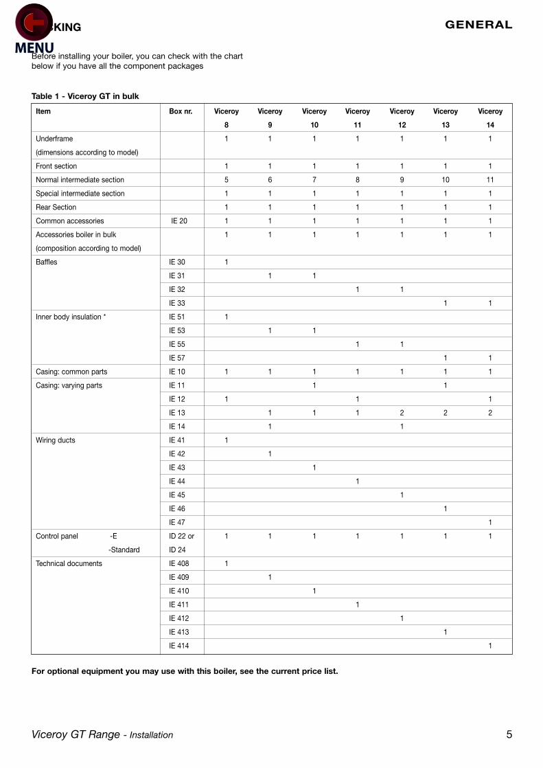
Before installing your boiler, you can check with the chartbelow if you have all the component packages
For optional equipment you may use with this boiler, see the current price list.
GENERALPACKING
Item Box nr. Viceroy Viceroy Viceroy Viceroy Viceroy Viceroy Viceroy
8 9 10 11 12 13 14
Underframe 1 1 1 1 1 1 1
(dimensions according to model)
Front section 1 1 1 1 1 1 1
Normal intermediate section 5 6 7 8 9 10 11
Special intermediate section 1 1 1 1 1 1 1
Rear Section 1 1 1 1 1 1 1
Common accessories IE 20 1 1 1 1 1 1 1
Accessories boiler in bulk 1 1 1 1 1 1 1
(composition according to model)
Baffles IE 30 1
IE 31 1 1
IE 32 1 1
IE 33 1 1
Inner body insulation * IE 51 1
IE 53 1 1
IE 55 1 1
IE 57 1 1
Casing: common parts IE 10 1 1 1 1 1 1 1
Casing: varying parts IE 11 1 1
IE 12 1 1 1
IE 13 1 1 1 2 2 2
IE 14 1 1
Wiring ducts IE 41 1
IE 42 1
IE 43 1
IE 44 1
IE 45 1
IE 46 1
IE 47 1
Control panel -E ID 22 or 1 1 1 1 1 1 1
-Standard ID 24
Technical documents IE 408 1
IE 409 1
IE 410 1
IE 411 1
IE 412 1
IE 413 1
IE 414 1
Table 1 - Viceroy GT in bulk

GENERAL
6 Viceroy GT Range - Installation
2 INSTALLATION OF THE BOILERThe minimum dimensions indicated on the following drawingmust be respected to ensure good access around the boiler
Remark: To allow the inlet of the combustion air, the boilerroom must be adequately ventilated, the section and thelocation must comply with local recommendations.
* Caution: Pay particular care to the space required for the boiler when the door is open. For an installation of severalboilers side by side, these dimensions need to be modified.
Sections 8 9 10 11 12 13 14
Dimensions A mm 1505 1665 1825 1985 2145 2305 2465
Dimensions B mm 130 -40 120 -40 120 -40 120
Dimensions C m 1.5 2 2 2 2.5 2.5 2.5
Section cm2 S 840 960 1090 1240 1390 1550 1710
Burner door open
8229-EN-05 A
8229-EN-54

Ventilation General
Detailed recommendations for air supply are quoted in BS.6644. The ventilation requirements in this gas fired boilerstandard are also valid for oil fired boilers of the same heatinput.
INSTALLATION
Viceroy GT Range - Installation 7
4 HYDRAULIC CONNECTIONDimensional information required
Remark: We draw your attention to the risks of corrosion ofboilers which are installed in or near rooms in which theatmosphere can be polluted by chloride or fluoridesubstances.
E.g. : industrial buildings (solvents), refrigerating machines,etc...
In these cases, we cannot provide a warranty.
Installation Recommendations
The installation of the boiler MUST be in accordance with thefollowing British Standards and Codes of Practice:BS. 799 Pts. 4,5,6 & 7 Oil Burning EquipmentBS. 5410 Pts. 2 & 3 Installations for Space Heating and
Hot water SystemsBS. 5449 Pt.1 Hot Water SystemsBS. 5854 Flues and Flue Structures in BuildingsBS. 5885 Pt.1 Gas Burners - with outputs of
60kW upwardsBS.6644 Installation of Gas Fired BoilersBS.6880 Low Temperature Hot Water Heating
SystemsBS.6891 Low Pressure Gas PipeworkBritish Gas Industrial Gas Fired Boilers andPublication No. IM.11 Air Heaters
The following must be confirmed with:Current Building Regulations and Clean Air ActWater Authority RegulationsLocal Authority Regulations and Regional bylawsGas Safety Regulations
Any Special regional requirements of local Electricity and Gasundertaking.Fire Service and Insurance Company requirements.All electrical wiring MUST comply with the current I.E.E.regulations for the electrical equipment of buildings. In theinterests of safety, a competent installer should be employedto effect the installation of the appliance. Manufacturer’snotes must NOT, in any way, be taken as over ridingstatutory obligations.
3 ASSEMBLYFor the assembly of the boiler, refer to the removable leafletin the middle of the instruction book.
Water flow/return tappingGT 8 to 10: Ø 2”1/2GT 11 to 14: Ø 3”
Threaded drain 2”
Viceroy ViceroyGT 8 to 10 GT 11 to 14
D mm 235 254E mm 1427 1447
8229-EN-06

INSTALLATION
8 Viceroy GT Range - Installation
Example of installation of a Viceroy GT boiler with productionof domestic hot water through independent calorifier(s)
1. Water flow flange2. Water return flange3. 4 bars safety valve + manometer*4. Flow control device5. Air separator6. Air vent7. Valve8. Recycling pump9. Expansion tank10. Drain valve11. Desludging valve12. Mixing valve13. Check valve14. Circulating pump15. Pressure gauge
16. Sludge decantation pot(particularly recommendation for older installations)
17. Independent calorifier18. Safety unit, set and sealed at 7 bars with over flow19. Pressure reducer (if system pressure >5.5bars)20. Domestic cold water inlet21. Domestic hot water flow22. Calorifier heating pump23. Domestic water circulating pump (optional)24. DHW circuit return25. Water meter (eventually)26. Water treatment when TH > 25°27. Heating system filler
(with circuit breaker in accordance with regulations).
* 6 bars maxi
Heating Circuit
FILLING THE INSTALLATION
The boiler may be filled by the drain tap. Filling should bedone at a slow flow rate in order to purge all the aircontained in the boiler by the upper point of the installation.Filling is always done with circulating pumps stopped.
General
Recommendations relating to the water system are containedin BS.5449 Pt.1, BS5401 Pt.2. and BS.6880.
MOST IMPORTANT: start up after partial ortotal drain of the installation:
If all air does not purge naturally via an opened expansionsystem, then in addition to automatic airvents able to ensurecontinuous automatic elimination of air from the system whileit is running, the installation must also include manualairvents so that all upper points of the installation can bevented and so that when the installation is full of water it canbe verified that all air is eliminated before the boiler are fired.
8219-EN-12
INSTALLATION
Viceroy GT Range - Installation 9
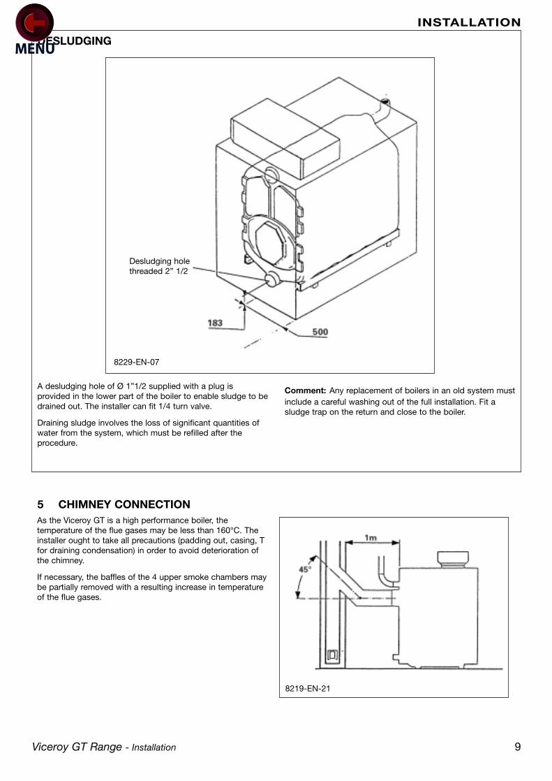
DESLUDGING
Desludging holethreaded 2” 1/2
A desludging hole of Ø 1”1/2 supplied with a plug isprovided in the lower part of the boiler to enable sludge to bedrained out. The installer can fit 1/4 turn valve.
Draining sludge involves the loss of significant quantities ofwater from the system, which must be refilled after theprocedure.
Comment: Any replacement of boilers in an old system mustinclude a careful washing out of the full installation. Fit asludge trap on the return and close to the boiler.
5 CHIMNEY CONNECTIONAs the Viceroy GT is a high performance boiler, thetemperature of the flue gases may be less than 160°C. Theinstaller ought to take all precautions (padding out, casing, Tfor draining condensation) in order to avoid deterioration ofthe chimney.
If necessary, the baffles of the 4 upper smoke chambers maybe partially removed with a resulting increase in temperatureof the flue gases.
8229-EN-07
8219-EN-21

INSTALLATION
10 Viceroy GT Range - Installation
DETERMINING THE FLUE
DIMENSIONAL INFORMATION NEEDED FOR CONNECTION
To size the height and cross section of the chimney, refer tothe regulations currently in force. GT boilers are boilers withpressurised combustion chambers and the pressure of theoutlet must not exceed 0 mbar unless special precautionsare taken to seal carefully between the outlet and the flue.
The installer should provide a measuring point (Ø 10mm hole)on the flue for burner adjustment and control of thecombustion.
Detailed recommendations, relating to the design of flues forGAS fired appliances are quoted in BS.6644 and British GasPublication No. IM 11., whilst BS.5410 Pt.3 similarly appliesOIL fired burners.
Chimney connection (outer Ø)
VICEROY GT 8 to 10: Ø 250
VICEROY GT 11 to 14: Ø 300
CONNECTION
Connection should be made according to regulation andpractice by using a sealed pipe in a material able towithstand hot combustion gases and possible acidiccondensation. The connection should be removable andpresent minimal loss of load, it means it should be as shortas possible and without sudden change of cross section.
Its diameter should always be at least equal to that of theboiler outlet, 250mm for the 8, 9 and 10 section boilers and300mm for the 11, 12, 13 and 14 section boilers.
8229-EN-08

INSTALLATION
Viceroy GT Range - Installation 11
6 OIL OR GAS CONNECTIONSee specific technical information supplied with the burner.
Caution: The baffle at the head of the burner must be in linewith the burner door insulation level.
Drilling Ø for burner door (on request).
Gas Supply
The gas supply MUST be sized in accordance with BritishGas recommendations and be fabricated in compliance withCP.331 Pt.3 any Local Gas Board installation standards.
The Local Gas Board should be contacted, at a stage prior toactual installation, for any advice or information required.Details and advice, relating to the use of L.P.G. for firing theIDEAL VICEROY GT range of heating boilers, are available onrequest to Caradon Ideal Ltd.
Oil Storage Tank
The oil storage tank, oil supply pipe and connections to theburner unit MUST comply with the requirements of BS.779and CP.5410.
The installation should conform to the recognised standardsof good practice in the trade and comply with the relevantCodes of Practice, Building Regulations and Local Authority,Fire and insurance requirements.
** maxi diameter for fixing:Ø B maxi = 290 mm
or Ø B maxi = 330 with 4 fixings at 15° or at 45°
Ø A 135 175 190 240 250 290Ø B** 170 200 220 270 325 330Ø M 8 8 10 10 14 12
8229-EN-10
Burner doorinsulation
Baffle
8229-EN-09

INSTALLATION
12 Viceroy GT Range - Installation
7 ELECTRICAL CONNECTIONS TO THE CONTROL PANELCAUTION: The connection must be carried out by aqualified professional.
As the electrical wiring has been carefully checked in thefactory, the internal connections of the control panel mustnot be modified under any circumstances.
The electrical connections of the boiler must conform withthe IEE wiring regulations in force and with the specificationsshown on the electrical drawings provided with theequipment, and the instructions given below.
The equipment should be supplied by a circuit using anomnipolar circuit breaker with an opening gap greater than3mm.
DELUXE - control panel
All the connections are made to the 2 terminal blocksprovided for this purpose in the control panel.
The connection cables are routed towards the front via the 2cut outs in the panel behind the boiler, and run in the wiringduct towards the panel via the two rectangular cut outs ofthe front top panel. The senor cables run on one side, thecables carrying the 230 V supply on the other and aresupported on both sides by plastic clips.
Caution: The sensor wiring must be kept separate fromthe other circuits. Inside the boiler, use the cable runs.Outside the boiler, 2 wiring ducts at least 10cm apartshould be used.
Wiring is secured in the control panel using cable clips (6cable clips are supplied in a separate packet); these are tobe fitted into the control panel base - see diagram below.
Caution: The maximum current which may be switchedby the outlet is 2 A, cos ϕ = 0.7 (= 450 W at he motor of0.5 Méch., hp signal current less than 16 A), if the chargeexceeds one of these values, the control must be relayedby means of a contractor. The outlet group is protectedby a 5 A fuse.
8229-EN-44
INSTALLATION
Viceroy GT Range - Installation 13
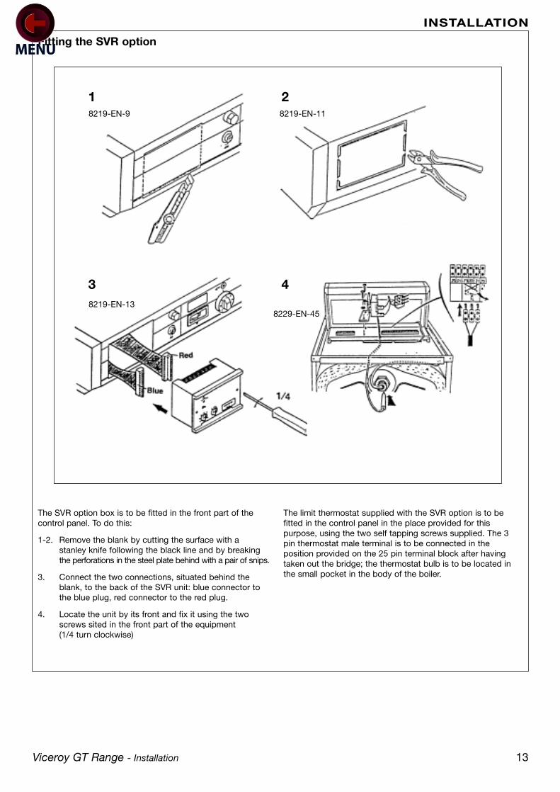
Fitting the SVR option
The SVR option box is to be fitted in the front part of thecontrol panel. To do this:
1-2. Remove the blank by cutting the surface with a stanley knife following the black line and by breaking the perforations in the steel plate behind with a pair of snips.
3. Connect the two connections, situated behind the blank, to the back of the SVR unit: blue connector to the blue plug, red connector to the red plug.
4. Locate the unit by its front and fix it using the two screws sited in the front part of the equipment(1/4 turn clockwise)
The limit thermostat supplied with the SVR option is to befitted in the control panel in the place provided for thispurpose, using the two self tapping screws supplied. The 3pin thermostat male terminal is to be connected in theposition provided on the 25 pin terminal block after havingtaken out the bridge; the thermostat bulb is to be located inthe small pocket in the body of the boiler.
1 2
3 48219-EN-13
8219-EN-9
8229-EN-45
8219-EN-11

INSTALLATION
14 Viceroy GT Range - Installation
The SV-matic weather compensator is fitted in the front partof the control panel. To do this:
1-2. Remove the blank by cutting the surface with a stanley knife following the black line and by breaking the perforations in the steel plate behind with a pair of snips.
3. Connect the two connections, situated behind the blank, to the back of the SVR unit: blue connector to the blue plug, red connector to the red plug.
4. Locate the unit by its front and fix it using the two screws sited in the front part of the equipment(1/4 turn clockwise)
Caution: When a two stage SV-matic weather compensator type322 DB is fitted, the resistor and the bridge respectively fittedbetween terminals 34 and 37, and 34 and 35 must be removed.
1 2
3
Fitting an SV-matic weather compensator
8219-EN-9
8219-EN-14
8219-EN-11
INSTALLATION
Viceroy GT Range - Installation 15
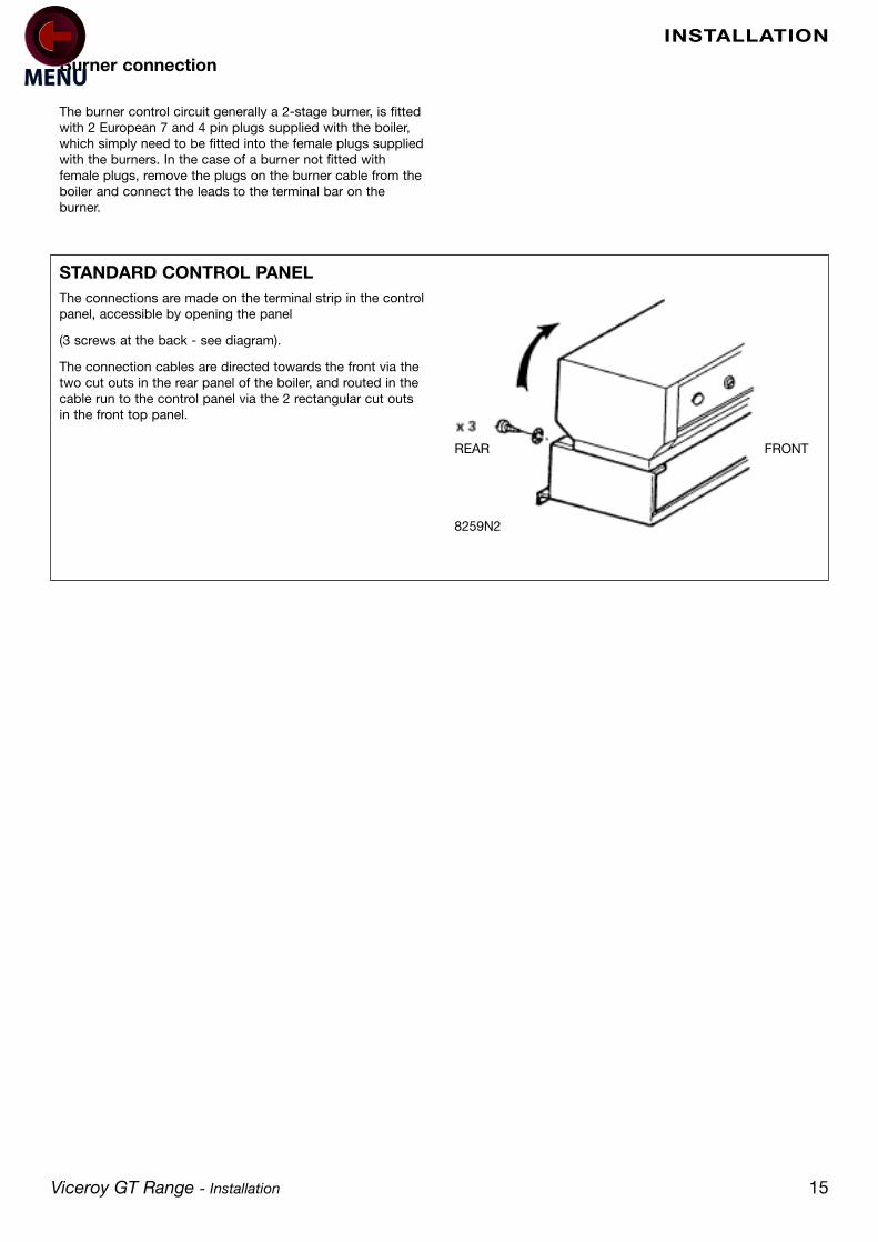
STANDARD CONTROL PANELThe connections are made on the terminal strip in the controlpanel, accessible by opening the panel
(3 screws at the back - see diagram).
The connection cables are directed towards the front via thetwo cut outs in the rear panel of the boiler, and routed in thecable run to the control panel via the 2 rectangular cut outsin the front top panel.
The burner control circuit generally a 2-stage burner, is fittedwith 2 European 7 and 4 pin plugs supplied with the boiler,which simply need to be fitted into the female plugs suppliedwith the burners. In the case of a burner not fitted withfemale plugs, remove the plugs on the burner cable from theboiler and connect the leads to the terminal bar on theburner.
Burner connection
REAR FRONT
8259N2
ASSEMBLY
16 Viceroy GT Range - Installation
8 START UP
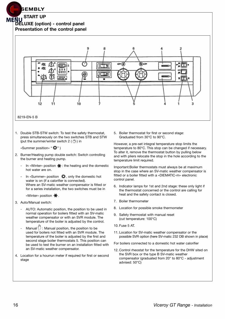
1. Double STB-STW switch: To test the safety thermostat, press simultaneously on the two switches STB and STW (put the summer/winter switch 2 ( ) in
«Summer position» “ ” )
2. Burner/Heating pump double switch: Switch controlling the burner and heating pump.
- In «Winter» position : the heating and the domestichot water are on.
- In «Summer» position , only the domestic hot water is on (if a calorifier is connected).Where an SV-matic weather compensator is fitted or for a series installation, the two switches must be in
«Winter» position .
3. Auto/Manual switch:
- AUTO: Automatic position, the position to be used in normal operation for boilers fitted with an SV-matic weather compensator or with an SVR module. The temperature of the boiler is adjusted by the control.
- Manual : Manual position, the position to be used for boilers not fitted with an SVR module. The temperature of the boiler is adjusted by the first and second stage boiler thermostats 5. This position can be used to test the burner on an installation fitted withan SV-matic weather compensator.
4. Location for a hourrun meter if required for first or secondstage
5. Boiler thermostat for first or second stage:Graduated from 30°C to 90°C.
However, a pre-set integral temperature stop limits thetemperature to 80°C. This stop can be changed if necessary.To alter it, remove the thermostat button by pulling belowand with pliers relocate the stop in the hole according to thetemperature limit required.
Important:Boiler thermostats must always be at maximumstop in the case where an SV-matic weather compensator isfitted or a boiler fitted with a «DIEMATIC-m» electroniccontrol panel.
6. Indicator lamps for 1st and 2nd stage: these only light if the thermostat concerned or the control are calling for heat and the safety contact is closed.
7. Boiler thermometer
8. Location for possible smoke thermometer
9. Safety thermostat with manual reset(cut temperature: 100°C)
10. Fuse 5 AT.
11. Location for SV-matic weather compensator or the possible SVR option (here SV-matic 232 DB shown in place)
For boilers connected to a domestic hot water calorifier
12. Control rheostat for the temperature for the DHW sited onthe SVR box or the type B SV-matic weather compensator (graduated from 20° to 80°C - adjustment advised: 50°C)
DELUXE (option) - control panelPresentation of the control panel
8219-EN-5 B

ASSEMBLY
Viceroy GT Range - Installation 17
Operating instructions of the Deluxe control panel
Regulation of the boiler:
The boiler is controlled either by the boiler thermostats or bythe SV-matic weather compensator (in option).
For boilers fitted with an SV-matic weather compensator thetemperature of the boiler is controlled by the action of theregulator on the burner according to the externaltemperature. The boiler thermostats will be then set to maxi.Operating safety is ensured by the safety thermostat withmanual reset.
For boilers fitted with an SV-matic weather compensatoracting on a valve, heating temperature is adjusted by theregulator on a motorised mixer valve according to theoutside temperature.
Regulation of domestic hot water
With SVR option or SV-matic type B:
The temperature of the domestic hot water is adjusted by arheostat 12 located on the SVR or SV-matic weathercompensator. When the domestic hot water is heated, theburner and load pump start while the heating acceleratorstops; the temperature of the boiler is then regulated by thelimit thermostat incorporated in the SV-matic weathercompensator or mounted on the SVR option (this thermostatis pre-set from factory at 80°C)
Once the hot water demand is satisfied, the burner stopsand the load pump continues to operate for 4 minutes (timingadjustable from 30 seconds to 15 minutes). This enables theresidual calories within the body of the heater to be used,and to complete the heating of the calorifier particularly insummer.
Start up
Before starting the boiler, check that the installation isproperly filled with water.
Make the start up adjustments in the following chronologicalorder:
Put the boiler thermostats 5 to the desired position (altering the position of the stop if necessary).
Important: For boilers fitted with an SV-matic weather compensator adjust the boiler thermostats to max.
Put the domestic hot water thermostat 12 to the desired temperature (SVR or SV-matic options). The temperature of the hot water thermostat must always be lower than the setting on the first stage boiler thermostat (or the limitthermostat in the unique case of the SVR option).
Put switch 3:
Either on manual position : Boilers not fitted with an SV-matic weather compensator.
Or on automatic position “AUTO”: Boilers fitted with an SV-matic weather compensator.
Check that the safety thermostat 9 is not tripped. To do this, unscrew the hexagonal cap and using a suitable screwdriver, press on the reset button.
Put the burner/accelerator switch 2 on winter position
IMPORTANT: In the absence of other settings. it is advisednever to set the boiler thermostat under mark 4 (40°C) so asto avoid all risk of condensation inside the boiler.
“ ”.

18 Viceroy GT Range - Installation
ASSEMBLYASSEMBLY
1. Stop/Start switch for the burner
2. STB test switch: momentary action to test the safety thermostat
3. Boiler thermostat first and second stage: Graduated from 30° to 90°C. Integral pre-set stop limits the maximum temperature to 80°C. This stop can be adjusted if necessary. To adjust it, remove the thermostat button by pulling and use pliers to move the stop to the hole according to the temperature desired.
The second stage thermostat must always be set to a lowervalue than the first stage thermostat.
4. Boiler thermometer
5. Location for possible smoke thermometer
6. 5 AT fuse
7. Safety thermostat with manual reset(factory set at 100°C)
Standard control panel presentation
Operating principle of the control panel
Adjustment and regulation of the boiler is done by boilerthermostats or by adjustments on the external control unit, ifthere is one. Operating safety is ensured by the manual resetsafety thermostat.
Start up
Put the boiler thermostat 3 on the desired position (alter thestop position if necessary). Where a control unit is fitted, seeinformations supplied with this control unit.
Check that the safety thermostat 7 is not tripped. To do this,unscrew the hexagonal cap and using a suitable screwdriver,press on the reset button.
Put the burner switch 1 on run
Important: in the absence of other settings, it is advisednever to set the boiler thermostat lower than mark 4 (40°C)so as to avoid all risk of condensation inside the boiler.
8219-EN-5
Viceroy GT Range - Installation 19
ASSEMBLY
Boiler
It is not advisable to drain an installation, except in case ofabsolute necessity. Check regularly the water level of theinstallation and top it up if necessary, avoiding a sudden inletof cold water into the hot boiler.
This operation can only be done a few times a year;otherwise, look for the leakage and remedy it without delay.
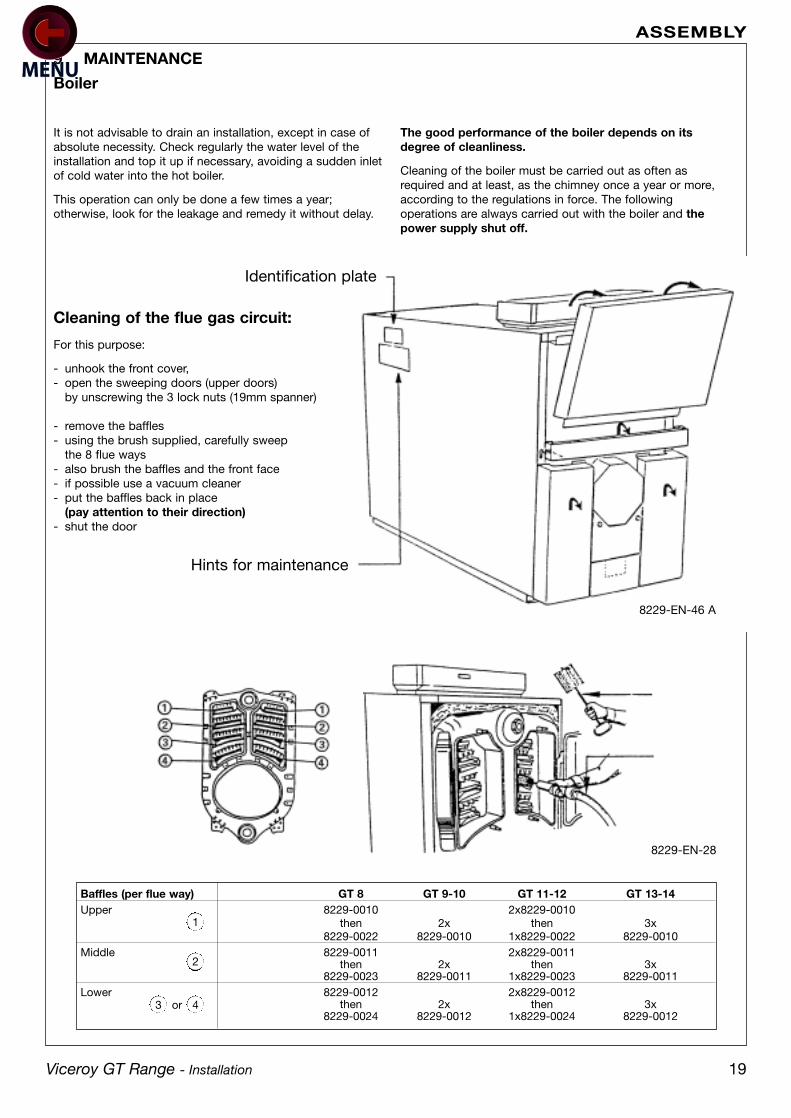
Cleaning of the flue gas circuit:
For this purpose:
- unhook the front cover,- open the sweeping doors (upper doors)
by unscrewing the 3 lock nuts (19mm spanner)
- remove the baffles- using the brush supplied, carefully sweep
the 8 flue ways- also brush the baffles and the front face- if possible use a vacuum cleaner- put the baffles back in place
(pay attention to their direction)- shut the door
The good performance of the boiler depends on itsdegree of cleanliness.
Cleaning of the boiler must be carried out as often asrequired and at least, as the chimney once a year or more,according to the regulations in force. The followingoperations are always carried out with the boiler and thepower supply shut off.
9 MAINTENANCE
Hints for maintenance
Identification plate
Baffles (per flue way) GT 8 GT 9-10 GT 11-12 GT 13-14Upper 8229-0010 2x8229-0010
then 2x then 3x8229-0022 8229-0010 1x8229-0022 8229-0010
Middle 8229-0011 2x8229-0011then 2x then 3x
8229-0023 8229-0011 1x8229-0023 8229-0011Lower 8229-0012 2x8229-0012
then 2x then 3x8229-0024 8229-0012 1x8229-0024 8229-0012
8229-EN-46 A
8229-EN-28
1
2
43 or

20 Viceroy GT Range - Installation
ASSEMBLY
Maintenance of the combustion chamber
- open the burner door (lower door) by unscrewing 4 lock nuts (19mm spanner)
- brush the inside of the combustion chamber
- using a vacuum cleaner, vacuum up the soot deposits accumulated in the combustion chamber
- close the door and replace the front cover
Cleaning the smoke box (flue hood)
For this purpose:
- remove the left and right hand sweeping covers of the smoke box (2 H12 nuts + washers - 19mm spanner) and remove the soot using a vacuum cleaner
- replace the sweeping covers
Precautions to be observed in case of very long stop of the boiler
- The boiler and the chimney must be carefully swept
- Shut the boiler doors to avoid any air flow inside
- If the boiler is going to be stopped for several months, we also advise removing the flue connection off the nozzle andto close it with a cover
- In case of stop of the heating in winter leading to risks of freezing, we advise the use of a concentrated antifreeze agent to prevent the heating water from freezing. Otherwise, completely drain the installation
VacuumCleaner

Viceroy GT Range - Installation 21
ASSEMBLY
Data notes
Fuel rates and flue gas data relates to maximum outputs ratingsGas firing data relates to the use of NATURAL GAS ONLYDetails for the use of LPG are available, on request, to Caradon Ideal LtdThe gas rate at calorific values differing from the standard quoted above may be calculated by direct proportionCALORIFIC VALUE; 38.5 MJ/m3 (1035 btu/ft3)
Boiler Size 8 9 10 11 12 13 14
Maximum Heat Output kW 390 450 540 600 670 720 780
Btu/h x 103 1,330 1,535 1,842 2,047 2,286 2,456 2,661
Minimum Heat Output kW 300 390 450 540 600 670 720
Btu/h x 103 1,024 1,330 1,535 1,842 2,047 2,286 2,456
Combustion Chamber Volume m3 0.31 0.35 0.39 0.44 0.48 0.52 0.57
ft3 10.9 12.5 13.9 15.5 16.9 18.5 19.9
Flue Way Content m3 0.56 0.64 0.71 0.78 0.86 0.93 1.01
ft3 19.8 22.5 25.1 27.8 30.4 32.9 35.6
Boiler Water Content l 366 409 452 495 538 581 624
gal 80.5 89.9 99.4 109 118.4 127.8 137.3
Hydraulic Resistance at 15k mbar 17 26.5 40.8 45.3 56.4 68.8 86.8
in.w.g. 6.8 10.6 16.3 18.1 22.5 27.5 34.7
Combustion Chamber Resistance mbar 1.1 1.5 2 2.5 2.5 2.5 3.5
in.w.g. 0.44 0.6 0.8 1 1 1 1.4
Boiler DRY weight less burner unit kg 1,470 1,650 1,830 2,010 2,190 2,370 2,550
lb 3,240 3,637 4,034 4,431 4,828 5,225 5,622
General Data
Boiler Size 8 9 10 11 12 13 14
Minimum Oil Rate l/h 39.71 45.85 55.02 61.13 68.26 73.36 79.47
gal/h 8.73 10.08 12.1 13.45 15.02 16.14 17.5
Maximum Flue Gas Volume l/sec 247.3 285.5 342.6 380.8 425.2 456.8 495.5
ft3/min 524 605 726 807 901 968 1,050
Oil Firing Data
Boiler Size 8 9 10 11 12 13 14
Minimum Gasl Rate m3/h 40.5 46.7 56.1 62.3 69.6 74.8 81
ft3/h 1,430 1,649 1,981 2,199 2,457 2,641 2,860
Maximum Flue Gas Volume m3/sec 0.24 0.28 0.33 0.37 0.41 0.45 0.48
ft3/min 8.47 9.88 11.65 13.06 14.47 15.8 16.9
Gas Firing Data
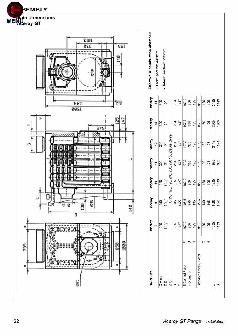
Main dimensionsViceroy GT
22 Viceroy GT Range - Installation
ASSEMBLY
Eff
ecti
ve Ø
co
mb
usti
on
cham
ber
:
-Fr
ont
sect
ion:
445
mm
-In
term
sec
tion:
530
mm
Boi
ler
Size
Vice
roy
Vice
roy
Vice
roy
Vice
roy
Vice
roy
Vice
roy
Vice
roy
89
1011
1213
14Ø
A o
ut.
250
250
250
300
300
300
300
Ø B
2 1 /
2”2
1 /2”
2 1 /
2”3”
3”3”
3ӯ
CØ
135
, 175
, 190
, 240
, 250
, 290
* o
u pl
aque
ple
ine
D23
523
523
525
425
425
425
4E
1427
1427
1427
1447
1447
1447
1447
E C
ontro
l Pan
el
F10
7,5
107,
510
7,5
107,
510
7,5
107,
510
7,5
+ D
iem
atic
G35
535
535
535
535
535
535
5H
195
195
195
195
195
195
195
Sta
ndar
d C
ontro
l Pan
el
F
127,
512
7,5
127,
512
7,5
127,
512
7,5
127,
5G
130
130
130
130
130
130
130
H10
510
510
510
510
510
510
5L
1505
1665
1825
1985
2145
2305
2465
S11
8313
4315
0316
6318
2319
8321
43
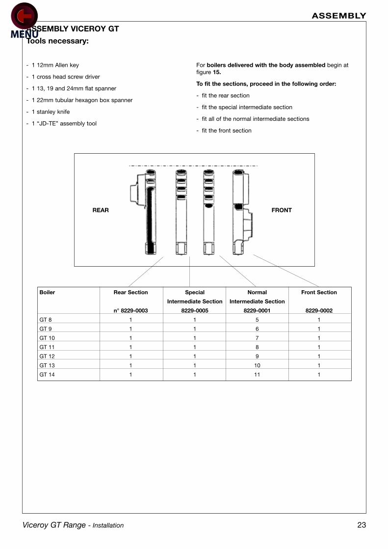
Tools necessary:
- 1 12mm Allen key
- 1 cross head screw driver
- 1 13, 19 and 24mm flat spanner
- 1 22mm tubular hexagon box spanner
- 1 stanley knife
- 1 “JD-TE” assembly tool
For boilers delivered with the body assembled begin atfigure 15.
To fit the sections, proceed in the following order:
- fit the rear section
- fit the special intermediate section
- fit all of the normal intermediate sections
- fit the front section
ASSEMBLY VICEROY GT
Viceroy GT Range - Installation 23
ASSEMBLY
FRONTREAR
Boiler Rear Section Special Normal Front Section
Intermediate Section Intermediate Section
n° 8229-0003 8229-0005 8229-0001 8229-0002
GT 8 1 1 5 1
GT 9 1 1 6 1
GT 10 1 1 7 1
GT 11 1 1 8 1
GT 12 1 1 9 1
GT 13 1 1 10 1
GT 14 1 1 11 1
24
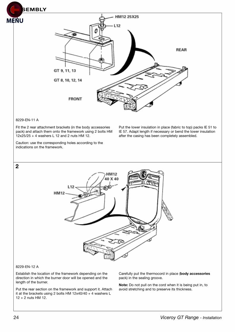
1
2
Fit the 2 rear attachment brackets (in the body accessoriespack) and attach them onto the framework using 2 bolts HM12x25/25 + 4 washers L 12 and 2 nuts HM 12.
Caution: use the corresponding holes according to theindications on the framework.
Put the lower insulation in place (fabric to top) packs IE 51 toIE 57. Adapt length if necessary or bend the lower insulationafter the casing has been completely assembled.
8229-EN-11 A
Establish the location of the framework depending on thedirection in which the burner door will be opened and thelength of the burner.
Put the rear section on the framework and support it. Attachit at the brackets using 2 bolts HM 12x40/40 + 4 washers L12 + 2 nuts HM 12.
Carefully put the thermocord in place (body accessoriespack) in the sealing groove.
Note: Do not pull on the cord when it is being put in, toavoid stretching and to preserve its thickness.
8229-EN-12 A
Viceroy GT Range - Installation
ASSEMBLY

25
5
Clean the bores and nipples with a diluent (body accessoriespack). Coat them with the lubricant supplied with the sections.
Drive in the 2 nipples gently.
8229-EN-13
Place the special intermediate section, taking care to present itthe correct way: the sealing groove against the thermocord.
For reasons of safety, insert an upper assembly rod (bodyaccessories pack) into the holes of the 2 sections.
Gently and at the same time drive in the 2 nipples of the rearsection using a hammer and a piece of wood, in line with thebores.
8199-EN-36
8229-EN-55
3 4
Viceroy GT Range - Installation
ASSEMBLY

26 Viceroy GT Range - Installation
ASSEMBLY
6
7
Fit the remaining sections in the order given (1 by 1)proceeding as per figures 3, 4, 5 and 6. Leave the assemblytool in place.
8229-EN-17 B
Put the special assembly tool in place. Tighten progressively,so as to bring the upper and lower connections togetherequally and at the same time.
8229-EN-16
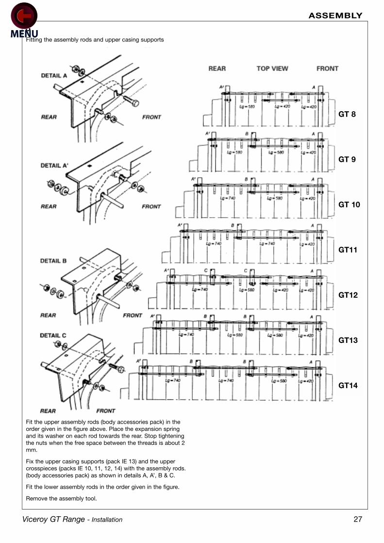
27
Fit the upper assembly rods (body accessories pack) in theorder given in the figure above. Place the expansion springand its washer on each rod towards the rear. Stop tighteningthe nuts when the free space between the threads is about 2mm.
Fix the upper casing supports (pack IE 13) and the uppercrosspieces (packs IE 10, 11, 12, 14) with the assembly rods.(body accessories pack) as shown in details A, A’, B & C.
Fit the lower assembly rods in the order given in the figure.
Remove the assembly tool.
Fitting the assembly rods and upper casing supports
8
Viceroy GT Range - Installation
ASSEMBLY
GT 8
GT 9
GT 10
GT11
GT12
GT13
GT14
28 Viceroy GT Range - Installation
ASSEMBLY
9
10
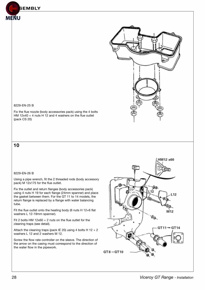
Using a pipe wrench, fit the 2 threaded rods (body accessorypack) M 12x175 for the flue outlet.
Fix the outlet and return flanges (body accessories pack)using 4 nuts H 19 for each flange (24mm spanner) and placethe gasket between them. For the GT 11 to 14 models, thereturn flange is replaced by a flange with water balancingtube.
Fit the flue outlet onto the heating body (6 nuts H 12+6 flatwashers L 12-19mm spanner).
Fit 2 bolts HM 12x60 + 2 nuts on the flue outlet for thecleaning traps (see detail).
Attach the cleaning traps (pack IE 20) using 4 bolts H 12 + 2washers L 12 and 2 washers M 12.
Screw the flow rate controller on the sleeve. The direction ofthe arrow on the casing must correspond to the direction ofthe water flow in the pipework.
8229-EN-26 B
Fix the flue nozzle (body accessories pack) using the 4 boltsHM 12x40 + 4 nuts H 12 and 4 washers on the flue outlet(pack CS 20)
8229-EN-25 B

29
12
Fit the lower and upper plugs with the small pocket (bodyaccessory pack). Do not forget the hemp.
Using a pipe wrench, put the 8 M 12x50 studs in place forthe cleaning doors and the burner door and the 2 M 12x85studs for the hinges of the sweeping doors.
Fit the hinges for the sweeping doors (pack IE 20) using 2bolts HM 12x25 + 2 nuts M 12 + 2 washers DE 12.
Fit the combustion chamber door hinge (body accessoriespack) on the left or the right according to the direction inwhich the door will be opened, and fix using 3 bolts HM12x30 + washers CL 14.
Fix the guide flap (body accessories pack) using 2 bolts HM12x25 + 2 washers CL 14.
8229-EN-18 C
Body accessories pack
Fit the burner door (4 M 12 nuts + washers CL 14).
Fit the hinge mounted on its pin.
8229-EN-20 A
11
Viceroy GT Range - Installation
ASSEMBLY
30
13
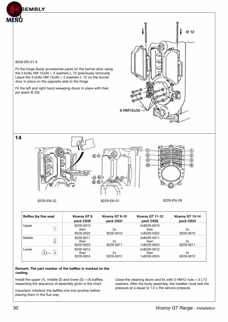
Fit the hinge (body accessories pack) on the burner door usingthe 3 bolts HM 12x30 + 3 washers L 12 (previously removed).Leave the 3 bolts HM 12x30 + 3 washers L 12 on the burnerdoor in place on the opposite side to the hinge.
Fit the left and right hand sweeping doors in place with theirpin (pack IE 20).
8229-EN-21 A
Remark: The part number of the baffles is marked on thecasting.
Install the upper (1), middle (2) and lower (3) + (4) baffles,respecting the sequence of assembly given in the chart.
Important: Interlock the baffles one into another beforeplacing them in the flue way.
Close the cleaning doors and fix with 3 HM12 nuts + 3 L12washers. After the body assembly, the installer must test thepressure at a equal to 1.5 x the service pressure.
8229-EN-22 8229-EN-51 8229-EN-28
Viceroy GT Range - Installation
ASSEMBLY
14
Baffles (by flue way) Viceroy GT 8 Viceroy GT 9-10 Viceroy GT 11-12 Viceroy GT 13-14pack CS30 pack CS31 pack CS32 pack CS33
Upper 8229-0010 2x8229-0010then 2x then 3x
8229-0022 8229-0010 1x8229-0022 8229-0010Middle 8229-0011 2x8229-0011
then 2x then 3x8229-0023 8229-0011 1x8229-0023 8229-0011
Lower 8229-0012 2x8229-0012then 2x then 3x
8229-0024 8229-0012 1x8229-0024 8229-0012
1
2
43 +

31
16
Fix the lower casing supports (pack IE 10 to IE 14) on theframework using 1 bolt HM 8x25 + lock washer for eachsupport.
8229-EN-23
Fit the body insulation panels. Bear up the insulation by tyingeach strap to the lower casing support at each side of theboiler.
8229-EN-50 A
Loosen the screw
Body delivered pre-assembledonly: IMPORTANT
8229-EN-24 A
Viceroy GT Range - Installation
ASSEMBLY
15
Boiler Body insulation widthFront Rear500 500 600 800 900
Viceroy GT 8 1 1Viceroy GT 9 1 1 1Viceroy GT 10 1 1 1Viceroy GT 11 1 1 1Viceroy GT 12 1 2 1Viceroy GT 13 1 2 1Viceroy GT 14 1 2 1Pack IE10 IE13 IE14 IE11 IE12
32
17
19
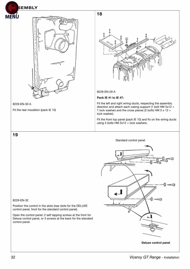
Fit the rear insulation (pack IE 10)
8229-EN-30 A
8229-EN-29 A
Pack IE 41 to IE 47:
Fit the left and right wiring ducts, respecting the assemblydirection and attach each casing support (1 bolt HM 5x12 +1 lock washer) and the cross pieces (2 bolts HM 5 x 12 +lock washer).
Fit the front top panel (pack IE 10) and fix on the wiring ductsusing 4 bolts HM 5x12 + lock washers.
Position the control in the slots (rear slots for the DELUXEcontrol panel, front for the standard control panel).
Open the control panel: 2 self tapping screws at the front forDeluxe control panel, or 3 screws at the back for the standardcontrol panel.
8229-EN-32
Standard control panel
Deluxe control panel
Viceroy GT Range - Installation
ASSEMBLY
18
33
22 23
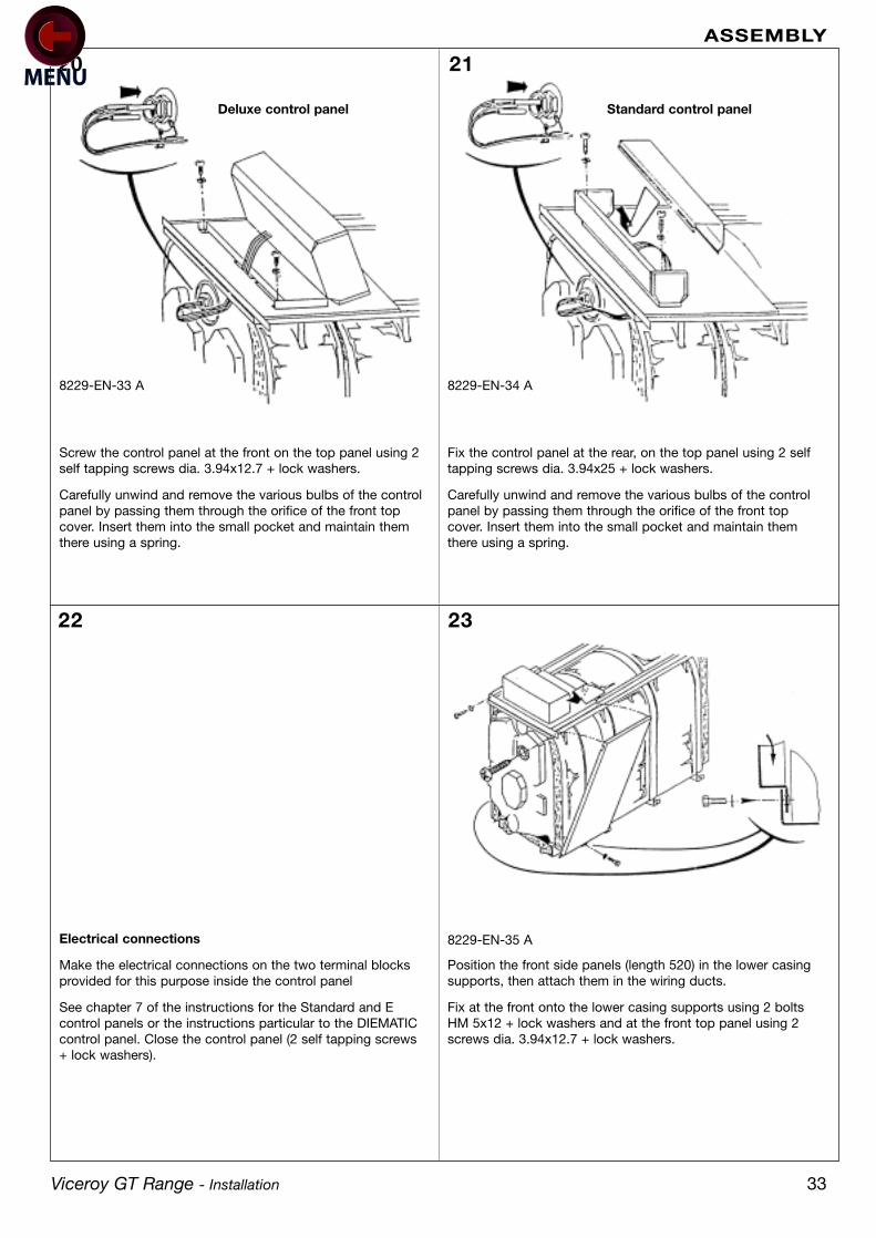
Screw the control panel at the front on the top panel using 2self tapping screws dia. 3.94x12.7 + lock washers.
Carefully unwind and remove the various bulbs of the controlpanel by passing them through the orifice of the front topcover. Insert them into the small pocket and maintain themthere using a spring.
Fix the control panel at the rear, on the top panel using 2 selftapping screws dia. 3.94x25 + lock washers.
Carefully unwind and remove the various bulbs of the controlpanel by passing them through the orifice of the front topcover. Insert them into the small pocket and maintain themthere using a spring.
8229-EN-33 A
Electrical connections
Make the electrical connections on the two terminal blocksprovided for this purpose inside the control panel
See chapter 7 of the instructions for the Standard and Econtrol panels or the instructions particular to the DIEMATICcontrol panel. Close the control panel (2 self tapping screws+ lock washers).
8229-EN-34 A
Position the front side panels (length 520) in the lower casingsupports, then attach them in the wiring ducts.
Fix at the front onto the lower casing supports using 2 boltsHM 5x12 + lock washers and at the front top panel using 2screws dia. 3.94x12.7 + lock washers.
8229-EN-35 A
Standard control panelDeluxe control panel
20 21
Viceroy GT Range - Installation
ASSEMBLY

34
24
25
Fit the remaining side panels in the order given in the table:position each panel in the lower casing supports then attachit in the wiring duct.
8229-EN-36
Fix the top covers from front to rear in the order given in thetable.
Fix the first intermediate top cover (length 480) onto thewiring duct using 4 bolts HM 5x12 + lock washers.
Fix the remaining top covers onto the wiring duct using 2bolts 5x12 + lock washers.
8229-EN-37
Viceroy GT Range - Installation
ASSEMBLY
Boiler Body insulation widthFront Rear
Viceroy GT 8 520(IE10) 930(IE12)Viceroy GT 9 520(IE10) 480(IE13) 610(IE14)Viceroy GT 10 520(IE10) 480(IE13) 770(IE11)Viceroy GT 11 520(IE10) 480(IE13) 930(IE12)Viceroy GT 12 520(IE10) 480(IE13) 480(IE13) 610(IE14)Viceroy GT 13 520(IE10) 480(IE13) 480(IE13) 770(IE11)Viceroy GT 14 520(IE10) 480(IE13) 480(IE13) 930(IE12)
Boiler Front Top Intermediate Rear PackPanel Top Panel Top Panel
Viceroy GT 8 480(IE10) 480 490 IE12Viceroy GT 9 480(IE10) 480 480 170 IE13 + IE14Viceroy GT 10 480(IE10) 480 480 330 IE11 + IE13Viceroy GT 11 480(IE10) 480 480 490 IE12 + IE13Viceroy GT 12 480(IE10) 480 480 480 170 IE14 + IE13Viceroy GT 13 480(IE10) 480 480 480 330 IE11 + IE13Viceroy GT 14 480(IE10) 480 480 480 490 IE12 + IE13
35
28
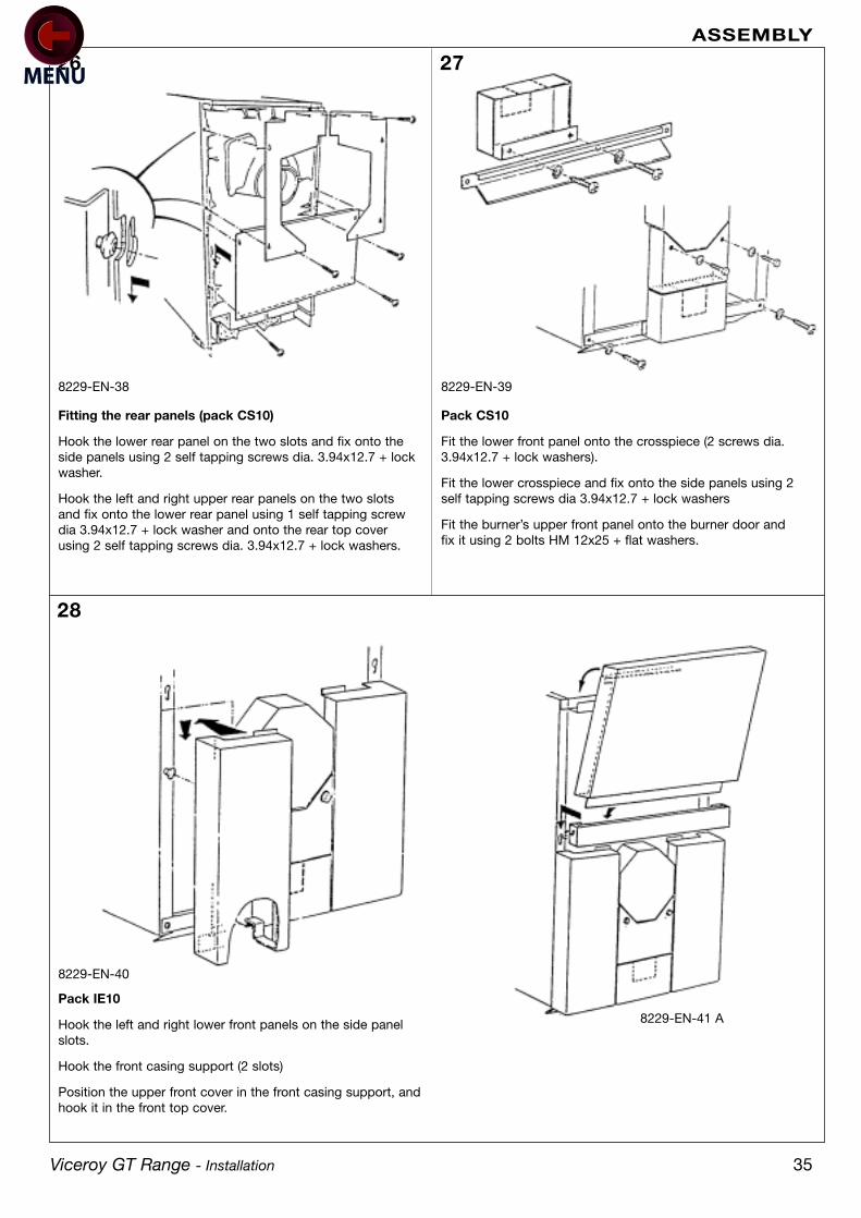
Fitting the rear panels (pack CS10)
Hook the lower rear panel on the two slots and fix onto theside panels using 2 self tapping screws dia. 3.94x12.7 + lockwasher.
Hook the left and right upper rear panels on the two slotsand fix onto the lower rear panel using 1 self tapping screwdia 3.94x12.7 + lock washer and onto the rear top coverusing 2 self tapping screws dia. 3.94x12.7 + lock washers.
8229-EN-38
Pack IE10
Hook the left and right lower front panels on the side panelslots.
Hook the front casing support (2 slots)
Position the upper front cover in the front casing support, andhook it in the front top cover.
8229-EN-40
8229-EN-41 A
26
Pack CS10
Fit the lower front panel onto the crosspiece (2 screws dia.3.94x12.7 + lock washers).
Fit the lower crosspiece and fix onto the side panels using 2self tapping screws dia 3.94x12.7 + lock washers
Fit the burner’s upper front panel onto the burner door andfix it using 2 bolts HM 12x25 + flat washers.
8229-EN-39
27
Viceroy GT Range - Installation
ASSEMBLY

GR
GR
EY
NO
BLA
CK
MA
BR
OW
NR
OR
ED
OR
OR
AN
GE
BL
BLU
EV
IV
IOLE
TB
AW
HIT
EV
/JG
REEN
/YEL
LOW
ALI
Mai
n S
upp
lyB
Bur
ner
BA
Con
nect
ing
Boa
rdF5
ATFu
se 5
A D
elay
edL
Pha
seN
Neu
tral
TCH
1B
oile
r Th
erm
osta
t 1s
t S
tage
TCH
2B
oile
r Th
erm
osta
t 2n
d S
tage
TS1
Saf
ety
Ther
mos
tat
TS2
Con
den
sor
Ther
mos
tat
TWS
afet
y Li
mite
r Th
erm
osta
tVA
Ala
rm In
dic
ator
ZB
Bur
ner
Sw
itch
ZTB
Test
Sw
itch
STB
ZTW
Test
Sw
itch
TW
•O
ptio
nal D
eliv
ered
Ear
th
36 Viceroy GT Range - Installation
ASSEMBLY
Standard Control PanelViceroy GT

37Viceroy GT Range - Installation
ASSEMBLY
Deluxe Control PanelViceroy GT
AH
eatin
g P
ump
ALI
Mai
n S
upp
lyB
AC
onne
ctin
g B
oard
BB
urne
rC
A1
Cas
cad
e co
nnec
tion
1C
A2
Cas
cad
e co
nnec
tion
2C
H1
Hou
r ru
n m
eter
1st
sta
geC
H2
Hou
r ru
n m
eter
2nd
sta
geC
SS
afet
y C
onta
ctD
ED
ecou
plin
gE
CS
Dom
estic
hot
wat
erF5
ATFu
se 5
A D
elay
edL
Pha
se
LPP
ump
Log
icN
Neu
tral
P1
Load
Pum
pP
2S
hunt
Pum
pR
Res
ista
nce
1430
RG
Reg
ulat
orTC
H1
Boi
ler
Ther
mos
tat
1st
Sta
geTC
H2
Boi
ler
Ther
mos
tat
2nd
Sta
geTL
Lim
iter
Ther
mos
tat
TS1
Saf
ety
Ther
mos
tat
TS2
Con
den
sor
Ther
mos
tat
VAA
larm
Ind
icat
orV
B1
On/
off
ind
icat
or 1
st S
tage
VB
2O
n/of
f in
dic
ator
2nd
Sta
geV
3VTh
ree
Way
Val
veV
1G
ate
Valv
eZ
EH
(A)
Sum
mer
-Win
ter
Sw
itch
Hea
ting
Pum
pZ
EH
(B)
Sum
mer
-Win
ter
Sw
itch
Bur
ner
Hea
ting
Pum
pZ
MM
anua
l Mod
e S
witc
hZ
TBTe
st S
witc
h S
TBZ
TWTe
st S
witc
h TW
?E
arth
?O
ptio
nal D
eliv
ered
38 Viceroy GT Range - Installation
ASSEMBLY
Deluxe Control Panel Burner Connection
1st Stage operating indicator
Burner malfunction indicator
TCH1
Neutral
Earth
TS
TCH2
2nd Stage operating indicator
Additional plug for2-stage burner
Plug for singlestage burner
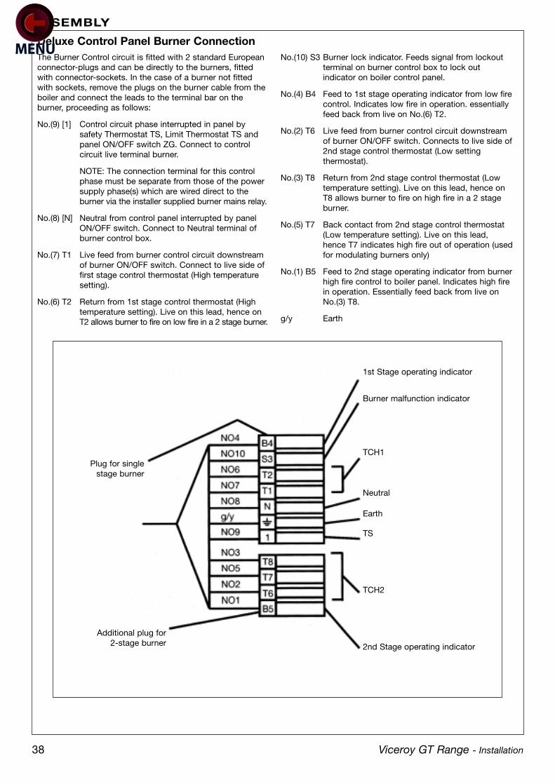
The Burner Control circuit is fitted with 2 standard Europeanconnector-plugs and can be directly to the burners, fittedwith connector-sockets. In the case of a burner not fittedwith sockets, remove the plugs on the burner cable from theboiler and connect the leads to the terminal bar on theburner, proceeding as follows:
No.(9) [1] Control circuit phase interrupted in panel by safety Thermostat TS, Limit Thermostat TS and panel ON/OFF switch ZG. Connect to control circuit live terminal burner.
NOTE: The connection terminal for this control phase must be separate from those of the power supply phase(s) which are wired direct to the burner via the installer supplied burner mains relay.
No.(8) [N] Neutral from control panel interrupted by panel ON/OFF switch. Connect to Neutral terminal of burner control box.
No.(7) T1 Live feed from burner control circuit downstream of burner ON/OFF switch. Connect to live side of first stage control thermostat (High temperature setting).
No.(6) T2 Return from 1st stage control thermostat (High temperature setting). Live on this lead, hence on T2 allows burner to fire on low fire in a 2 stage burner.
No.(10) S3 Burner lock indicator. Feeds signal from lockout terminal on burner control box to lock out indicator on boiler control panel.
No.(4) B4 Feed to 1st stage operating indicator from low firecontrol. Indicates low fire in operation. essentially feed back from live on No.(6) T2.
No.(2) T6 Live feed from burner control circuit downstream of burner ON/OFF switch. Connects to live side of2nd stage control thermostat (Low setting thermostat).
No.(3) T8 Return from 2nd stage control thermostat (Low temperature setting). Live on this lead, hence on T8 allows burner to fire on high fire in a 2 stage burner.
No.(5) T7 Back contact from 2nd stage control thermostat (Low temperature setting). Live on this lead, hence T7 indicates high fire out of operation (usedfor modulating burners only)
No.(1) B5 Feed to 2nd stage operating indicator from burnerhigh fire control to boiler panel. Indicates high fire in operation. Essentially feed back from live on No.(3) T8.
g/y Earth

40Viceroy GT Range - Installation
ASSEMBLY

PO Box 103National AvenueKingston upon HullHU5 4JNTelephone 01482 492251Facsimile 01482 448858
Registration No. 4049093Registered OfficeKelburn House7-19 Mosley StreetNewcastle Upon TyneNE1 1YE
Commercial Heating Technical Helpline 01482 498376
The Caradon Plumbing Limited Technical Training Centreoffers a series of first class training courses for domestic,commercial and industrial heating installers, engineers andsystem specifiers. For details of courses please ring:
Technical Training
. . . . . . . . . . . . . . . . . . . . . . . . . . . . . . . . . . . . . . . . . . . . . . . . . . . . . . . 01482 498432
Caradon Plumbing Limitedpursues a policy of continuingimprovement in the design andperformance of its products.The right is therefore reserved tovary specification without notice.
September 2001 AO 09/52