INSTALLATION VERSION 1 FOG LIGHTS INSTRUCTIONS 2017 … · FOG LIGHTS P/N 08V31-TZ5-200B 2017 MDX...
17
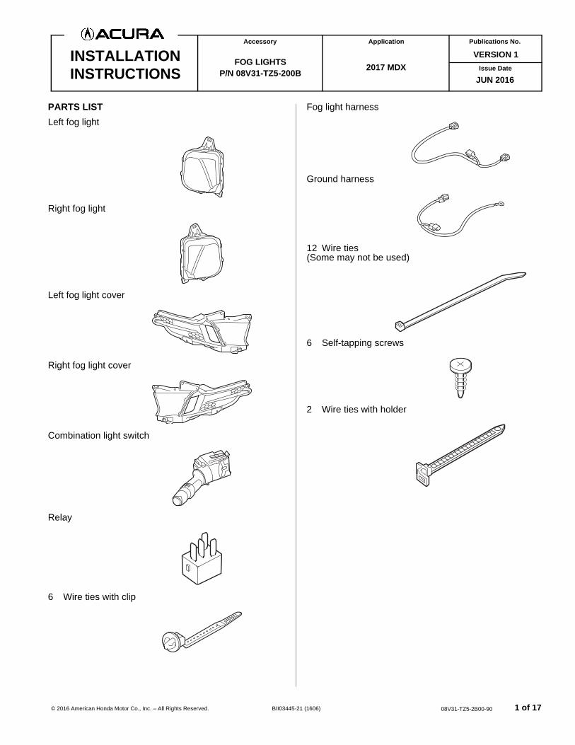
© 2016 American Honda Motor Co., Inc. – All Rights Reserved. BII03445-21 (1606) 1 of 17 08V31-TZ5-2B00-90 VERSION 1 Publications No. Issue Date INSTALLATION INSTRUCTIONS Accessory Application FOG LIGHTS P/N 08V31-TZ5-200B 2017 MDX JUN 2016 PARTS LIST Left fog light Right fog light Left fog light cover Right fog light cover Combination light switch Relay 6 Wire ties with clip Fog light harness Ground harness 12 Wire ties (Some may not be used) 6 Self-tapping screws 2 Wire ties with holder
Transcript of INSTALLATION VERSION 1 FOG LIGHTS INSTRUCTIONS 2017 … · FOG LIGHTS P/N 08V31-TZ5-200B 2017 MDX...
© 2016 American Honda Motor Co., Inc. – All Rights Re
VERSION 1Publications No.
INSTALLATIONINSTRUCTIONS
Accessory Application
FOG LIGHTSP/N 08V31-TZ5-200B
served. BII03445-21 (160
2017 MDX
6) 0
Issue Date
JUN 2016
PARTS LISTLeft fog light
Right fog light
Left fog light cover
Right fog light cover
Combination light switch
Relay
6 Wire ties with clip
Fog light harness
Ground harness
12 Wire ties(Some may not be used)
6 Self-tapping screws
2 Wire ties with holder
1 of 178V31-TZ5-2B00-90
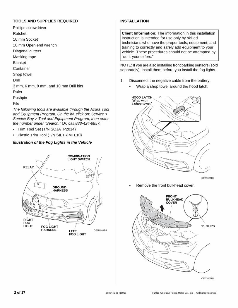
TOOLS AND SUPPLIES REQUIRED
Phillips screwdriverRatchet10 mm Socket10 mm Open end wrenchDiagonal cuttersMasking tapeBlanketContainerShop towelDrill3 mm, 6 mm, 8 mm, and 10 mm Drill bitsRulerPushpinFileThe following tools are available through the Acura Tool and Equipment Program. On the iN, click on: Service > Service Bay > Tool and Equipment Program, then enter the number under “Search.” Or, call 888-424-6857.• Trim Tool Set (T/N SOJATP2014)• Plastic Trim Tool (T/N SILTRIMTL10)
Illustration of the Fog Lights in the Vehicle
QEN1901BJ
RIGHT FOG LIGHT
LEFT FOG LIGHT
GROUND HARNESS
COMBINATION LIGHT SWITCH
FOG LIGHT HARNESS
RELAY
2 of 17 BII03445-2
INSTALLATION
NOTE: If you are also installing front parking sensors (sold separately), install them before you install the fog lights.
1. Disconnect the negative cable from the battery:• Wrap a shop towel around the hood latch.
• Remove the front bulkhead cover.
Client Information: The information in this installation instruction is intended for use only by skilled technicians who have the proper tools, equipment, and training to correctly and safely add equipment to your vehicle. These procedures should not be attempted by “do-it-yourselfers.”
QE03001BJ
HOOD LATCH(Wrap with a shop towel.)
QE03002BJ
11 CLIPS
FRONT BULKHEAD COVER
1 (1606) © 2016 American Honda Motor Co., Inc. – All Rights Reserved.
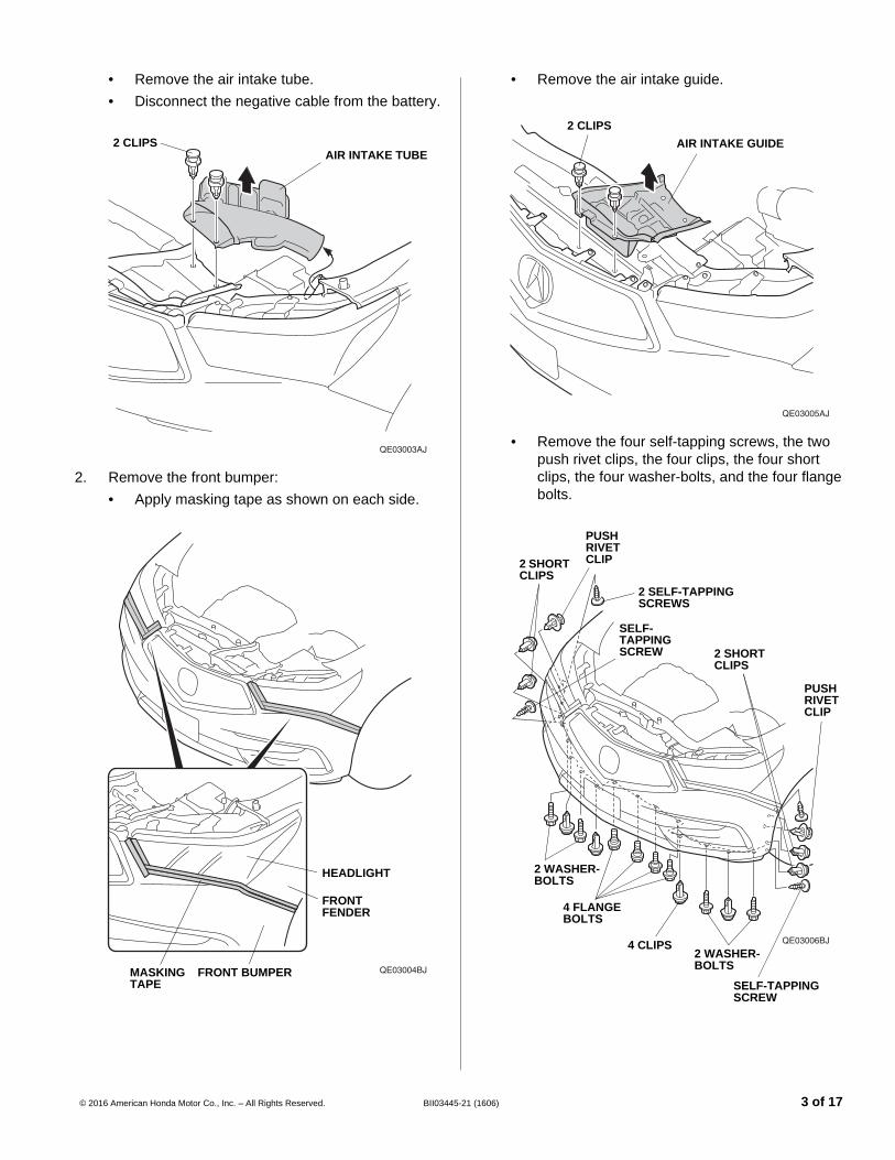
• Remove the air intake tube.• Disconnect the negative cable from the battery.
2. Remove the front bumper:• Apply masking tape as shown on each side.
QE03003AJ
2 CLIPSAIR INTAKE TUBE
QE03004BJMASKINGTAPE
FRONT BUMPER
HEADLIGHT
FRONT FENDER
© 2016 American Honda Motor Co., Inc. – All Rights Reserved. BII03445-2
• Remove the air intake guide.
• Remove the four self-tapping screws, the two push rivet clips, the four clips, the four short clips, the four washer-bolts, and the four flange bolts.
QE03005AJ
2 CLIPSAIR INTAKE GUIDE
QE03006BJ
SELF-TAPPING SCREW
4 CLIPS2 WASHER-BOLTS
4 FLANGE BOLTS
2 WASHER-BOLTS
2 SHORT CLIPS
2 SHORT CLIPS
PUSH RIVET CLIP
PUSH RIVET CLIP
2 SELF-TAPPING SCREWS
SELF-TAPPING SCREW
1 (1606) 3 of 17
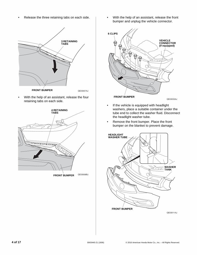
• Release the three retaining tabs on each side.
• With the help of an assistant, release the four retaining tabs on each side.
QE03007AJ
3 RETAINING TABS
FRONT BUMPER
QE03008BJ
4 RETAINING TABS
FRONT BUMPER
4 of 17 BII03445-2
• With the help of an assistant, release the front bumper and unplug the vehicle connector.
• If the vehicle is equipped with headlight washers, place a suitable container under the tube end to collect the washer fluid. Disconnect the headlight washer tube.
• Remove the front bumper. Place the front bumper on the blanket to prevent damage.
QE03033AJFRONT BUMPER
VEHICLE CONNECTOR(if equipped)
6 CLIPS
QE03011AJ
FRONT BUMPER
HEADLIGHT WASHER TUBE
WASHER TANK
1 (1606) © 2016 American Honda Motor Co., Inc. – All Rights Reserved.
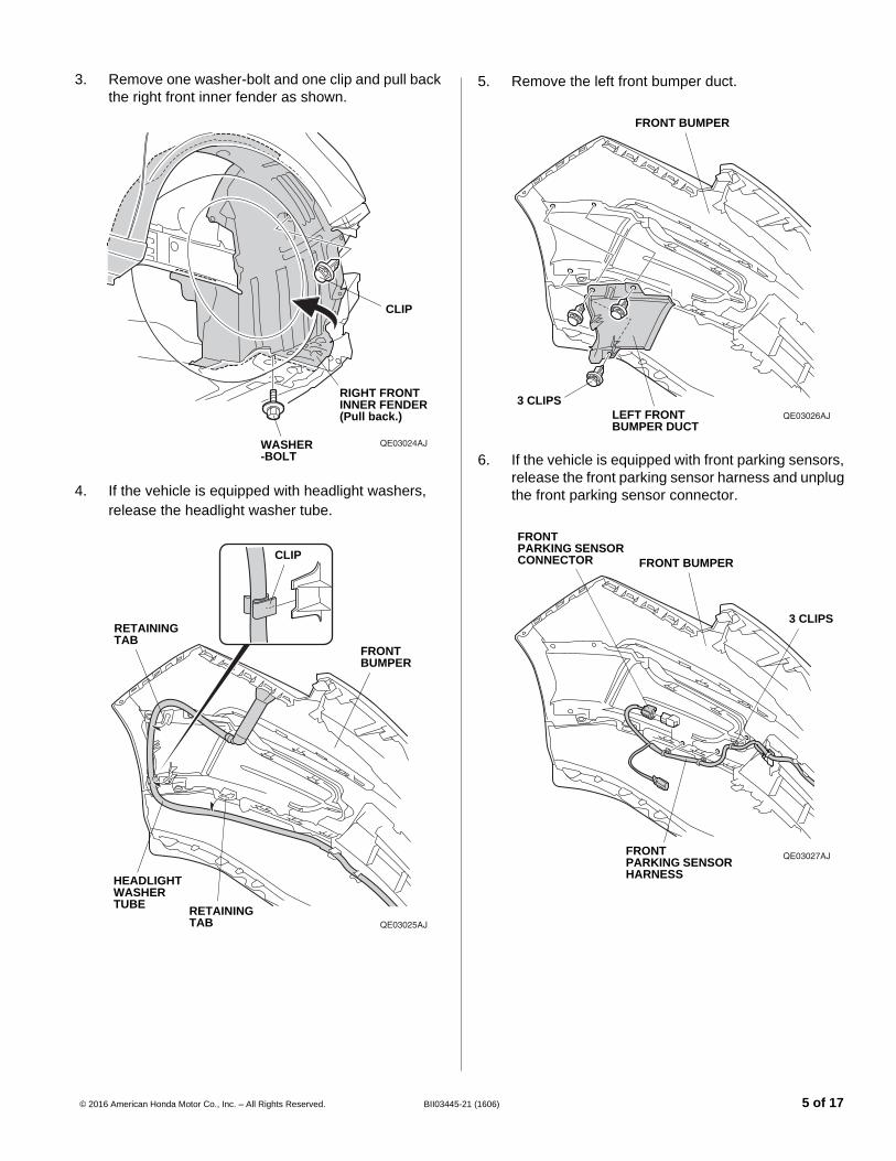
3. Remove one washer-bolt and one clip and pull back the right front inner fender as shown.
4. If the vehicle is equipped with headlight washers, release the headlight washer tube.
QE03024AJ
CLIP
RIGHT FRONT INNER FENDER(Pull back.)
WASHER-BOLT
QE03025AJ
FRONT BUMPER
CLIP
RETAINING TAB
HEADLIGHT WASHER TUBE
RETAINING TAB
© 2016 American Honda Motor Co., Inc. – All Rights Reserved. BII03445-2
5. Remove the left front bumper duct.
6. If the vehicle is equipped with front parking sensors, release the front parking sensor harness and unplug the front parking sensor connector.
QE03026AJ
3 CLIPSLEFT FRONT BUMPER DUCT
FRONT BUMPER
QE03027AJ
FRONT BUMPER
3 CLIPS
FRONT PARKING SENSOR HARNESS
FRONT PARKING SENSOR CONNECTOR
1 (1606) 5 of 17
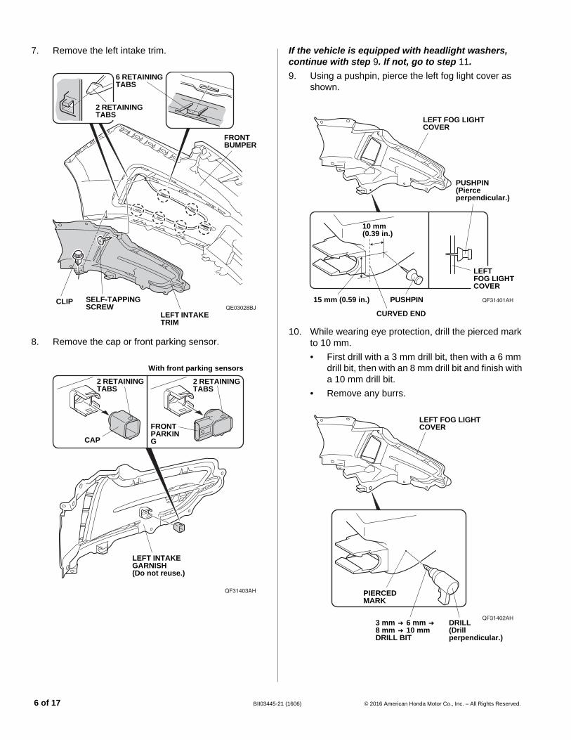
7. Remove the left intake trim.
8. Remove the cap or front parking sensor.
QE03028BJ
6 RETAINING TABS
FRONT BUMPER
LEFT INTAKE TRIM
SELF-TAPPING SCREW
CLIP
2 RETAINING TABS
QF31403AH
2 RETAINING TABS
CAP
FRONT PARKING
With front parking sensors
2 RETAINING TABS
LEFT INTAKE GARNISH(Do not reuse.)
6 of 17 BII03445-2
If the vehicle is equipped with headlight washers, continue with step 9. If not, go to step 11.9. Using a pushpin, pierce the left fog light cover as
shown.
10. While wearing eye protection, drill the pierced mark to 10 mm.• First drill with a 3 mm drill bit, then with a 6 mm
drill bit, then with an 8 mm drill bit and finish with a 10 mm drill bit.
• Remove any burrs.
QF31401AH
LEFT FOG LIGHT COVER
10 mm (0.39 in.)
15 mm (0.59 in.) PUSHPIN
PUSHPIN(Pierce perpendicular.)
LEFT FOG LIGHT COVER
CURVED END
QF31402AH
LEFT FOG LIGHT COVER
PIERCED MARK
DRILL(Drill perpendicular.)
3 mm 6 mm 8 mm 10 mm DRILL BIT
1 (1606) © 2016 American Honda Motor Co., Inc. – All Rights Reserved.
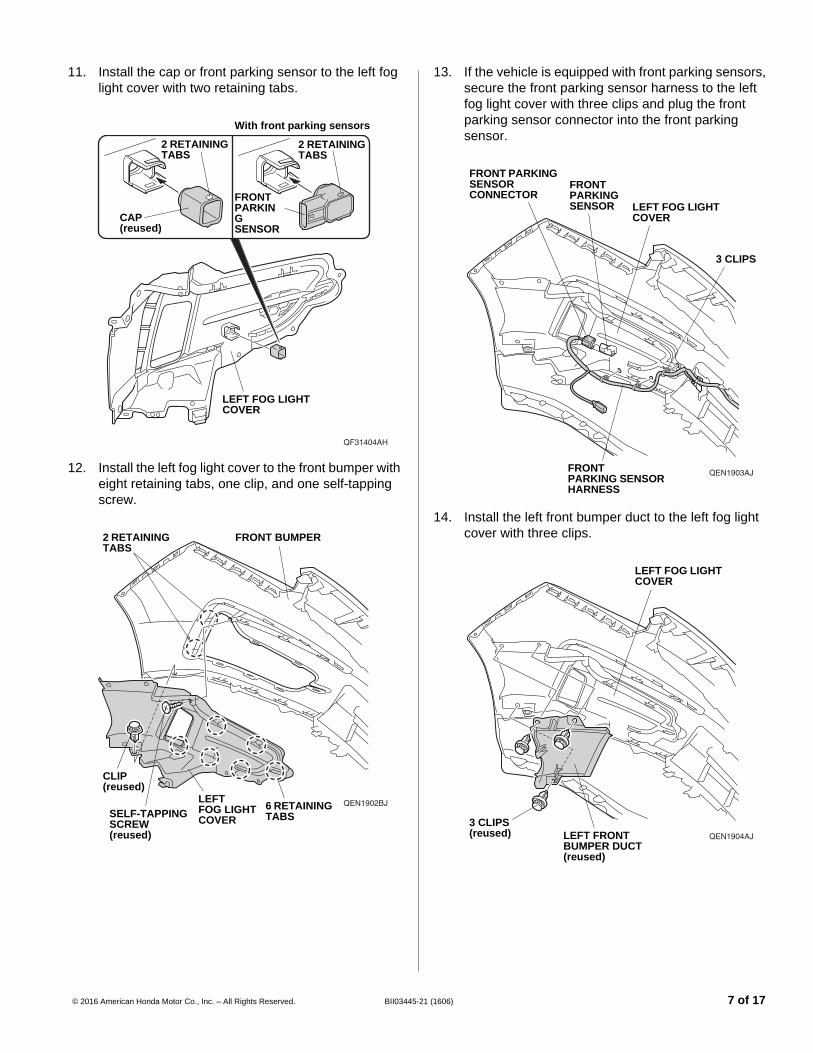
11. Install the cap or front parking sensor to the left fog light cover with two retaining tabs.
12. Install the left fog light cover to the front bumper with eight retaining tabs, one clip, and one self-tapping screw.
QF31404AH
2 RETAINING TABS
CAP(reused)
FRONT PARKING SENSOR
With front parking sensors
2 RETAINING TABS
LEFT FOG LIGHT COVER
QEN1902BJLEFT FOG LIGHT COVER
6 RETAINING TABS
FRONT BUMPER
SELF-TAPPING SCREW(reused)
CLIP(reused)
2 RETAINING TABS
© 2016 American Honda Motor Co., Inc. – All Rights Reserved. BII03445-2
13. If the vehicle is equipped with front parking sensors, secure the front parking sensor harness to the left fog light cover with three clips and plug the front parking sensor connector into the front parking sensor.
14. Install the left front bumper duct to the left fog light cover with three clips.
QEN1903AJ
LEFT FOG LIGHT COVER
3 CLIPS
FRONT PARKING SENSOR HARNESS
FRONT PARKING SENSOR
FRONT PARKING SENSOR CONNECTOR
QEN1904AJ
3 CLIPS(reused) LEFT FRONT
BUMPER DUCT(reused)
LEFT FOG LIGHT COVER
1 (1606) 7 of 17
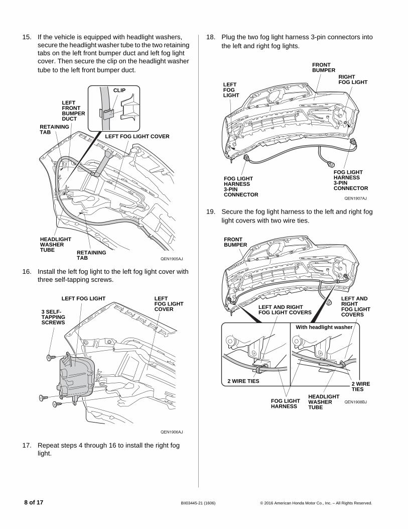
15. If the vehicle is equipped with headlight washers, secure the headlight washer tube to the two retaining tabs on the left front bumper duct and left fog light cover. Then secure the clip on the headlight washer tube to the left front bumper duct.
16. Install the left fog light to the left fog light cover with three self-tapping screws.
17. Repeat steps 4 through 16 to install the right fog light.
QEN1905AJ
LEFT FOG LIGHT COVER
CLIP
RETAINING TAB
HEADLIGHT WASHER TUBE
LEFT FRONT BUMPER DUCT
RETAINING TAB
QEN1906AJ
LEFT FOG LIGHT COVER3 SELF-
TAPPING SCREWS
LEFT FOG LIGHT
8 of 17 BII03445-2
18. Plug the two fog light harness 3-pin connectors into the left and right fog lights.
19. Secure the fog light harness to the left and right fog light covers with two wire ties.
QEN1907AJ
FRONT BUMPER
LEFT FOG LIGHT
RIGHT FOG LIGHT
FOG LIGHT HARNESS 3-PIN CONNECTOR
FOG LIGHT HARNESS 3-PIN CONNECTOR
QEN1908BJ
FRONT BUMPER
FOG LIGHT HARNESS
2 WIRE TIES
HEADLIGHT WASHER TUBE
2 WIRE TIES
With headlight washer
LEFT AND RIGHT FOG LIGHT COVERS
LEFT AND RIGHT FOG LIGHT COVERS
1 (1606) © 2016 American Honda Motor Co., Inc. – All Rights Reserved.
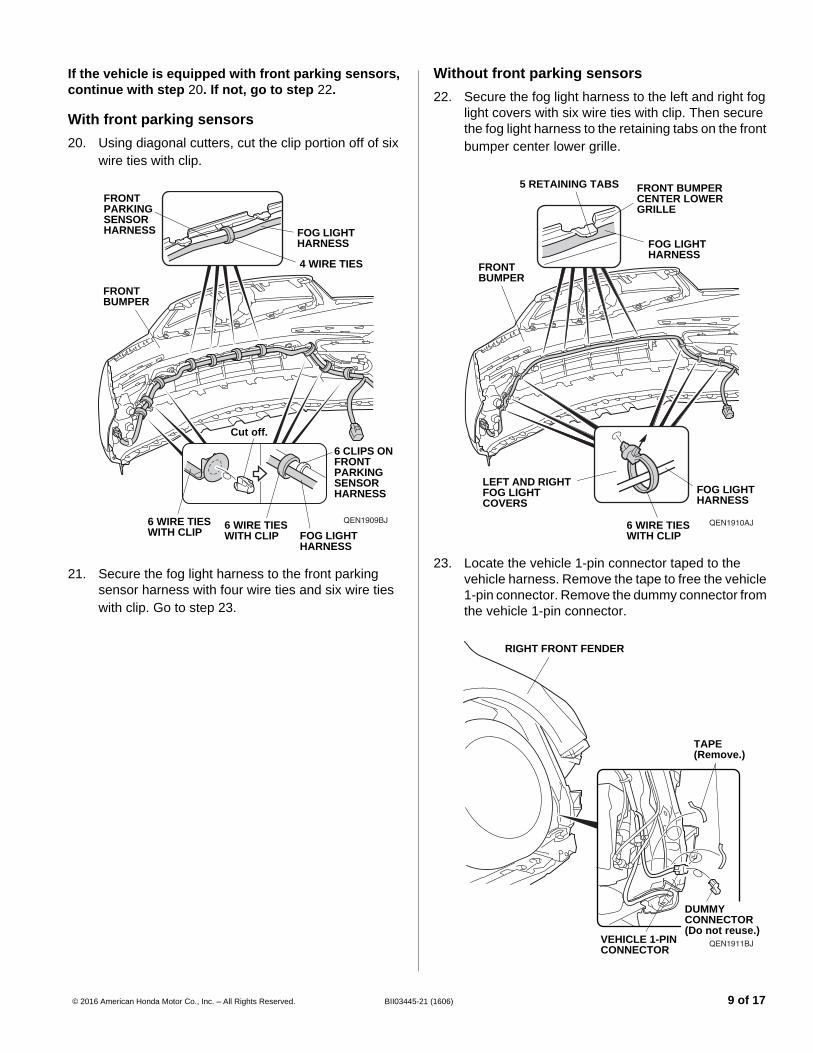
If the vehicle is equipped with front parking sensors, continue with step 20. If not, go to step 22.
With front parking sensors20. Using diagonal cutters, cut the clip portion off of six
wire ties with clip.
21. Secure the fog light harness to the front parking sensor harness with four wire ties and six wire ties with clip. Go to step 23.
QEN1909BJ
FRONT BUMPER
6 CLIPS ON FRONT PARKING SENSOR HARNESS
6 WIRE TIESWITH CLIP
FOG LIGHT HARNESS
FRONT PARKING SENSOR HARNESS
4 WIRE TIES
FOG LIGHT HARNESS
6 WIRE TIESWITH CLIP
Cut off.
© 2016 American Honda Motor Co., Inc. – All Rights Reserved. BII03445-2
Without front parking sensors22. Secure the fog light harness to the left and right fog
light covers with six wire ties with clip. Then secure the fog light harness to the retaining tabs on the front bumper center lower grille.
23. Locate the vehicle 1-pin connector taped to the vehicle harness. Remove the tape to free the vehicle 1-pin connector. Remove the dummy connector from the vehicle 1-pin connector.
QEN1910AJ
FRONT BUMPER
LEFT AND RIGHT FOG LIGHT COVERS
6 WIRE TIES WITH CLIP
FOG LIGHT HARNESS
5 RETAINING TABS FRONT BUMPER CENTER LOWER GRILLE
FOG LIGHT HARNESS
QEN1911BJVEHICLE 1-PIN CONNECTOR
TAPE (Remove.)
RIGHT FRONT FENDER
DUMMY CONNECTOR(Do not reuse.)
1 (1606) 9 of 17
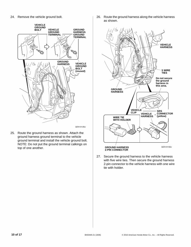
24. Remove the vehicle ground bolt.
25. Route the ground harness as shown. Attach the ground harness ground terminal to the vehicle ground terminal and install the vehicle ground bolt.NOTE: Do not put the ground terminal calkings on top of one another.
QEN1912BJ
GROUND HARNESS GROUND TERMINAL
VEHICLE GROUND BOLT(reused)
VEHICLE GROUND TERMINAL
GROUND HARNESS
VEHICLE GROUNDBOLT
10 of 17 BII03445-2
26. Route the ground harness along the vehicle harness as shown.
27. Secure the ground harness to the vehicle harness with five wire ties. Then secure the ground harness 2-pin connector to the vehicle harness with one wire tie with holder.
QEN1915BJ
GROUND HARNESS
5 WIRE TIES
VEHICLE HARNESS
Do not secure the ground harness in this area.
SRS CONNECTOR(yellow)
VEHICLE CLIP
GROUND HARNESS 2-PIN CONNECTOR
WIRE TIE WITH HOLDER
VEHICLE HARNESS
1 (1606) © 2016 American Honda Motor Co., Inc. – All Rights Reserved.
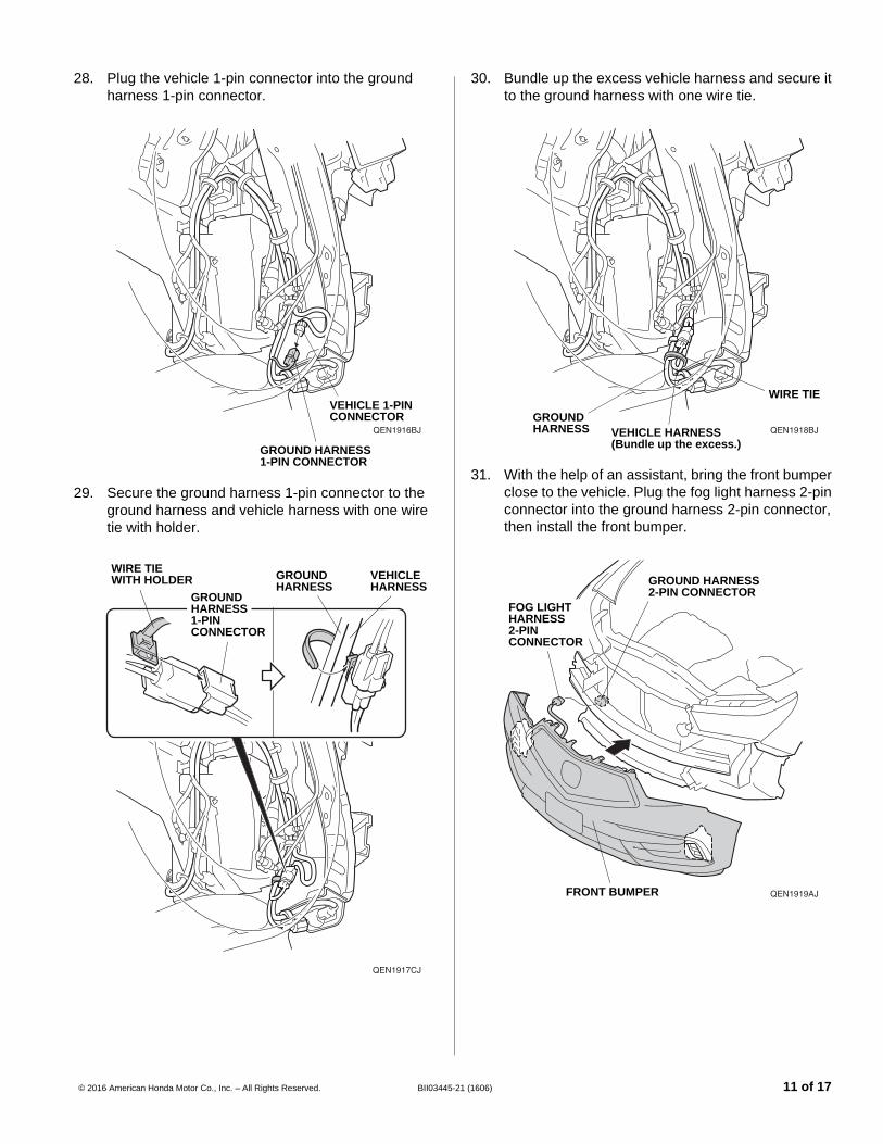
28. Plug the vehicle 1-pin connector into the ground harness 1-pin connector.
29. Secure the ground harness 1-pin connector to the ground harness and vehicle harness with one wire tie with holder.
QEN1916BJ
GROUND HARNESS 1-PIN CONNECTOR
VEHICLE 1-PIN CONNECTOR
QEN1917CJ
WIRE TIE WITH HOLDER
GROUND HARNESS 1-PIN CONNECTOR
GROUND HARNESS
VEHICLE HARNESS
© 2016 American Honda Motor Co., Inc. – All Rights Reserved. BII03445-2
30. Bundle up the excess vehicle harness and secure it to the ground harness with one wire tie.
31. With the help of an assistant, bring the front bumper close to the vehicle. Plug the fog light harness 2-pin connector into the ground harness 2-pin connector, then install the front bumper.
QEN1918BJGROUND HARNESS
WIRE TIE
VEHICLE HARNESS(Bundle up the excess.)
QEN1919AJ
GROUND HARNESS 2-PIN CONNECTOR
FRONT BUMPER
FOG LIGHT HARNESS 2-PIN CONNECTOR
1 (1606) 11 of 17
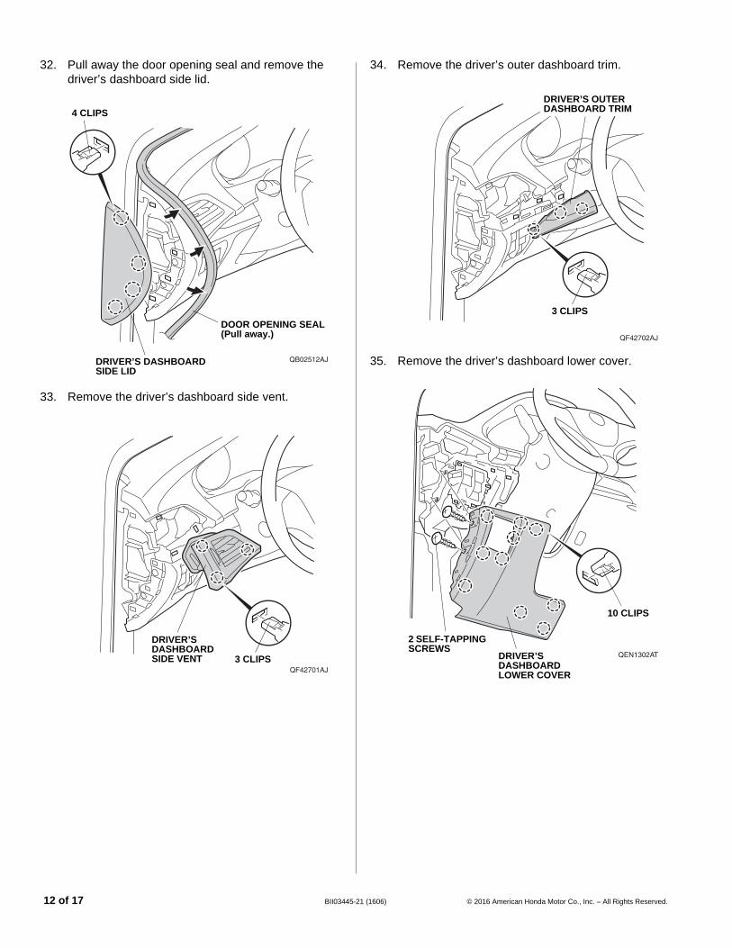
32. Pull away the door opening seal and remove the driver’s dashboard side lid.
33. Remove the driver’s dashboard side vent.
QB02512AJ
4 CLIPS
DOOR OPENING SEAL(Pull away.)
DRIVER’S DASHBOARD SIDE LID
QF42701AJ
DRIVER’S DASHBOARD SIDE VENT 3 CLIPS
12 of 17 BII03445-2
34. Remove the driver’s outer dashboard trim.
35. Remove the driver’s dashboard lower cover.
QF42702AJ
DRIVER’S OUTER DASHBOARD TRIM
3 CLIPS
QEN1302AT
10 CLIPS
DRIVER’S DASHBOARD LOWER COVER
2 SELF-TAPPING SCREWS
1 (1606) © 2016 American Honda Motor Co., Inc. – All Rights Reserved.
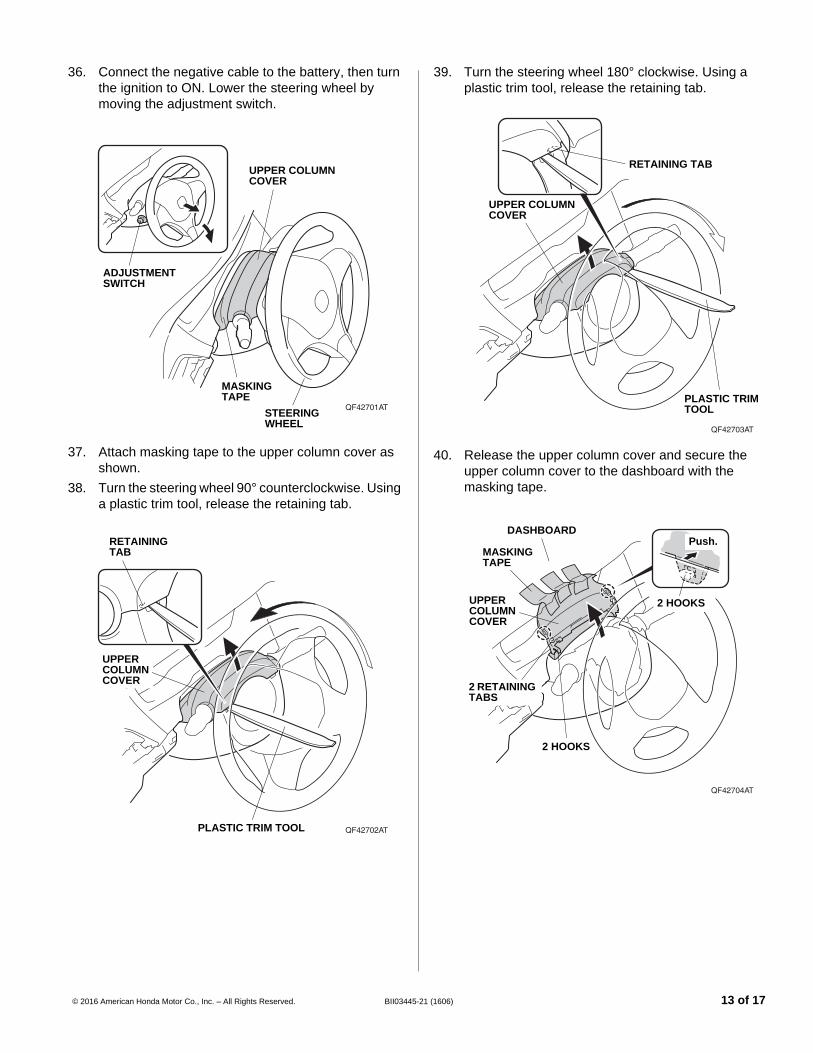
36. Connect the negative cable to the battery, then turn the ignition to ON. Lower the steering wheel by moving the adjustment switch.
37. Attach masking tape to the upper column cover as shown.
38. Turn the steering wheel 90° counterclockwise. Using a plastic trim tool, release the retaining tab.
QF42701AT
MASKINGTAPE
UPPER COLUMN COVER
STEERING WHEEL
ADJUSTMENT SWITCH
QF42702ATPLASTIC TRIM TOOL
RETAINING TAB
UPPER COLUMN COVER
© 2016 American Honda Motor Co., Inc. – All Rights Reserved. BII03445-2
39. Turn the steering wheel 180° clockwise. Using a plastic trim tool, release the retaining tab.
40. Release the upper column cover and secure the upper column cover to the dashboard with the masking tape.
QF42703AT
RETAINING TAB
UPPER COLUMN COVER
PLASTIC TRIM TOOL
QF42704AT
MASKINGTAPE
UPPER COLUMN COVER
DASHBOARD
2 HOOKS
2 HOOKS
2 RETAINING TABS
Push.
1 (1606) 13 of 17
41. Remove one self-tapping screw from the lower column cover.
42. Turn the steering wheel 180° counterclockwise and remove the other self-tapping screw from the lower column cover.
43. Turn the ignition to OFF.NOTE: The steering wheel automatically moves fully in and up. Make sure the steering wheel is not interfering with the vehicle parts.
44. Disconnect the negative cable from the battery.
QF42705AT
LOWER COLUMN COVER
SELF-TAPPING SCREW
QF42706AT
LOWER COLUMN COVER SELF-TAPPING
SCREW
14 of 17 BII03445-2
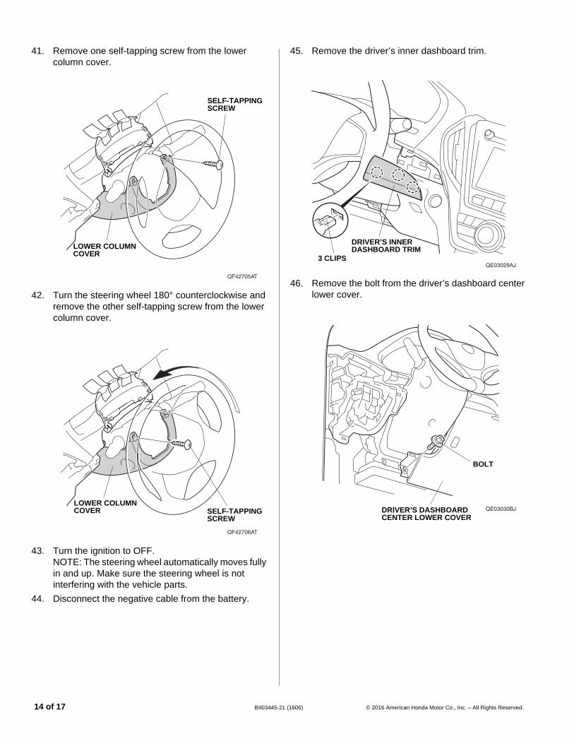
45. Remove the driver’s inner dashboard trim.
46. Remove the bolt from the driver’s dashboard center lower cover.
QE03029AJ3 CLIPS
DRIVER’S INNER DASHBOARD TRIM
QE03030BJ
BOLT
DRIVER’S DASHBOARD CENTER LOWER COVER
1 (1606) © 2016 American Honda Motor Co., Inc. – All Rights Reserved.
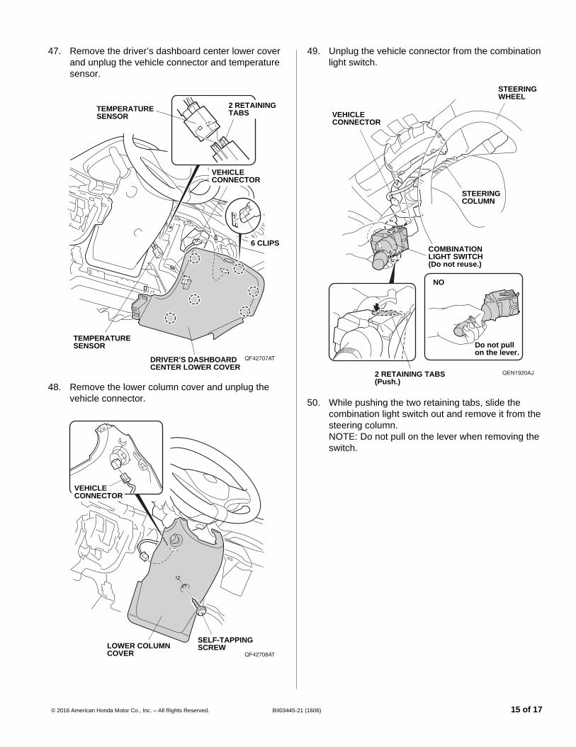
47. Remove the driver’s dashboard center lower cover and unplug the vehicle connector and temperature sensor.
48. Remove the lower column cover and unplug the vehicle connector.
QF42707AT
6 CLIPS
DRIVER’S DASHBOARD CENTER LOWER COVER
TEMPERATURE SENSOR
TEMPERATURE SENSOR
2 RETAINING TABS
VEHICLE CONNECTOR
QF42708AT
VEHICLE CONNECTOR
SELF-TAPPING SCREWLOWER COLUMN
COVER
© 2016 American Honda Motor Co., Inc. – All Rights Reserved. BII03445-2
49. Unplug the vehicle connector from the combination light switch.
50. While pushing the two retaining tabs, slide the combination light switch out and remove it from the steering column. NOTE: Do not pull on the lever when removing the switch.
QEN1920AJ
COMBINATION LIGHT SWITCH(Do not reuse.)
2 RETAINING TABS(Push.)
STEERING WHEEL
Do not pull on the lever.
STEERING COLUMN
VEHICLE CONNECTOR
NO
1 (1606) 15 of 17
51. Install the new combination light switch on the steering column. NOTE: Do not push on the lever when installing the switch.
52. Plug the vehicle connector into the new combination light switch. Make sure the vehicle harness has some slack.
QEN1921AJ
NEW COMBINATION LIGHT SWITCH
2 RETAINING TABS(Push.)
STEERING WHEEL
Do not push on the lever.
STEERING COLUMN
VEHICLE CONNECTOR
NO
16 of 17 BII03445-2
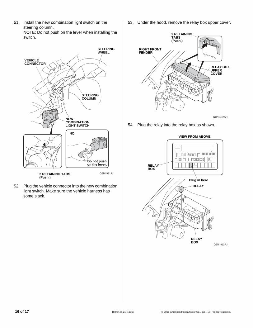
53. Under the hood, remove the relay box upper cover.
54. Plug the relay into the relay box as shown.
QBN1947AH
RELAY BOX UPPER COVER
2 RETAINING TABS(Push.)
RIGHT FRONT FENDER
QEN1922AJ
RELAY BOX
RELAY BOX
Plug in here.
VIEW FROM ABOVE
RELAY
1 (1606) © 2016 American Honda Motor Co., Inc. – All Rights Reserved.
55. Check that all wire harnesses are routed properly and all connectors are plugged in.
56. Install all removed parts except for the front bulkhead cover and the intake air tube.
57. Connect the negative cable to the battery.58. Install the front bulkhead cover and the intake air
tube.59. Press and hold the audio unit power button for 2
seconds to restore the audio and navi (if equipped) system functions.
60. Set the clock.61. If necessary restore the systems back to normal
operation as described in the service information.62. If necessary fill the washer tank to the proper level.
Check the Operation of the Fog Light
63. Turn the headlight switch to the AUTO or “ ” position (headlights on low beam).
64. Turn on the fog light switch (indicator is on).65. If the fog lights do not turn on, check the fuse and all
the connectors, including the ground cable.
NOTE: The fog light lenses may cloud when the outside temperature is cold; this is normal and should go away in warm weather.
QBN2108AH
FOG
LIG
HT
SW
ITC
H
HEADLIGHT SWITCH
Low HighOFF
OFF -
ON
- - -
- - -
© 2016 American Honda Motor Co., Inc. – All Rights Reserved. BII03445-2
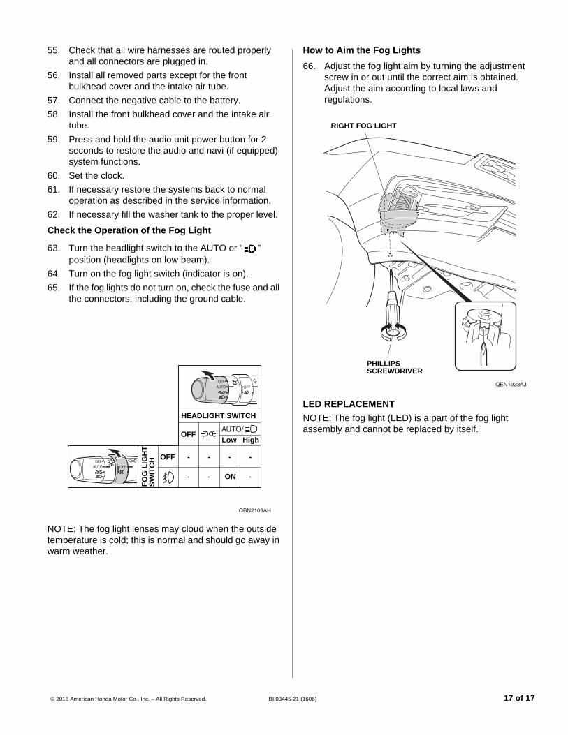
How to Aim the Fog Lights
66. Adjust the fog light aim by turning the adjustment screw in or out until the correct aim is obtained. Adjust the aim according to local laws and regulations.
LED REPLACEMENTNOTE: The fog light (LED) is a part of the fog light assembly and cannot be replaced by itself.
QEN1923AJ
RIGHT FOG LIGHT
PHILLIPS SCREWDRIVER
1 (1606) 17 of 17