23 mind blowing search engine marketing tips for global apparel & accessories industries

INSTALLATION TIPS AND ACCESSORIES
For most vehicles we have a T-Harness available to make your remote starter installation quicker and easier. To order visit us online at www.directwholesale.net.
Additional remote transmitters can be purchased through Direct Wholesale at www.directwholesale.net.
For a full list of Bulldog Security accessories visit our web site at www.bulldogsecurity.com.
Your Bulldog Security remote starter is equipped with an interactive install CD and installation kit. The kit will consist of a computer friendly test light, wire ties and a roll of tape. Use only the computer friendly test light or volt meter when testing and probing wires.
For Technical assistance www.bulldogsecurity.com can provide a detailed wiring diagram for your vehicle including additional helpful install tips.
JBS Technologies 225 Technology Way Steubenville Ohio 43952
WARRANTY
Bulldog Warranty InformationAll Bulldog models have a Limited Lifetime Warranty on the main control module.
All parts excluding the control module have a two-year warranty against defects in workmanship, This includes shock sensors, remote transmitters and sirens. The control module will be repaired or replaced at our dis-cretion for up to a 12 month period at no charge. After 12 months a $30.00 fee will be charged for repair or replacement of the control module.
Removal and reinstallation charges are not the respon-sibility of JBS Technologies, LLC the manufacturer of Bulldog Security. Warranty registration must be com-pleted within 7 days of the original date of purchase. Registration can be mailed in or performed on line at www.bulldogsecurity.com. JBS Technologies makes no warranty against the theft of a vehicle or its con-tents. This warranty only extends to the original system purchaser in the vehicle it was originally installed in.
Limitation of RemediesThe purchasers’ remedy is limited to the repair or replacement of the unit and in no event shall exceed the purchase price. Incidental, consequential and/or indirect damages are expressly disclaimed. No person or entity is authorized to alter or amend this limited lifetime warranty.
63

3
TRANSPONDER / PASSLOCK III
62
REQUIRED TOOLS ....................................................................... 5INSTALLATION CHECK LIST ........................................................ 5TECHNICAL ASSISTANCE ............................................................ 6BEFORE YOU BEGIN .................................................................... 6PRECAUTIONS .........................................................................7-8USING YOUR TEST PROBE .......................................................... 8MAKING WIRING CONNECTIONS ...........................................8-10COMPONENTS ........................................................................... 11WIRING DIAGRAMS ............................................................. 11-12 H1 – 6-PIN HEAVY GAUGE WIRING CONNECTIONS ................. 13-14 H1/1 Violet Wire – Starter Output ..............................................13 H1/2-3 Red Wire - +12V Power Input .........................................14 H1/4 Yellow Wire – Ignition 1 Output..........................................14 H1/5 Pink Wire – Ignition 2 Output ............................................14 H1/6 Brown Wire – Accessory Output (Heater/ACC Output) ........... 14H2 – 5 PIN WIRE HARNESS ...................................................... 15 H2/1 Red/White Wire – Parking Light Relay Power Input ............... 15 H2/2 White Wire – Parking Light Relay Output ............................. 15 H2/3 Black Wire – System Ground .............................................15 H2/4 Brown Wire – (-) 200 ma Horn Output ................................ 15 H2/5 Red Wire – System Power .................................................15H3 –BLACK 4-PIN CONNECTOR FOR TWO-WAY TRANSCEIVER/ANTENNA MODULE .......15-16H4 – 9-PIN BLACK WIRE HARNESS ......................................16-20 H4/1 Violet/White Wire – Tach Input Connection .......................... 16 H4/2 Thin Black Wire – (-) Neutral Safety Switch or ..................... 17 (-) Remote Toggle Switch Input H4/3 Brown/Red wire – (+) Positive Safety Shut Down Brake or Handbrake ........................ 17 H4/4 Grey wire – (-) Negative Safety Shut Down ......................... 17 For Hood Pin Switch H4/5 Red/White Wire – (-) 200mA Channel 3 Trunk Output ........... 18 H4/6 Brown/Black Wire – (-) 200mA Factory Security Rearm Signal/ Key Sensor Output ....................................................18 Factory Security Rearm Signal Output Ground Output During Start (Crank) H4/7 Black/White Wire–(-)200mA Dome Light Supervision Output . 19 H4/8 Lt. Green/Black Wire – (-) 200mA Programmable Output ...... 20
INSTALLATION TABLE OF CONTENTS
614
TRANSPONDER / PASSLOCK III
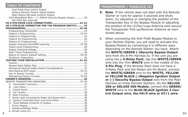
Note: If the vehicle does not start with the Remote Starter or runs for approx 5 seconds and shuts down, try adjusting or changing the position of the Transponder Key in the Bypass Module or adjusting the position of the (2)Two Loop Antenna wire around the Transponder Pick-up/Receiver Antenna as men-tioned above.
When connecting the Anti-Theft Bypass Module to your Remote Starter, you will need to activate this Bypass Module by connecting it in different ways depending on the Remote Starter you have. Attach the WHITE/GREEN (-)Security Bypass Output wire from the 8-Pin Harness to: if the unit you are using has a 4-Relay Pack, tap this WHITE/GREEN wire into the Thin WHITE wire in the middle of the 3-Pin Plug, if the Remote Start does not have a 4-Relay Pack and the Relays are On-Board, connect the WHITE/GREEN wire to the WHITE, YELLOW or YELLOW BLACK (-)Negative Ignition Output or (-) Security Bypass Output wire from the Main Harness on these Remote Starters. On the DELUXE 200 or DELUXE 500 Models, connect this GREEN/WHITE wire to the BLUE/BLACK Ignition 3 Con-trol Output wire, the H4/9 wire or H7/1 wire.
5.
6.
Dual Pulse Door Unlock Output Factory Security Disarm Signal Output Start Status (By-pass Control) Output H4/9 Blue/Black Wire – (-) 200mA Security Bypass Output ........... 20 GM VATS Key OverrideH5 6-PIN DOOR LOCK CONNECTIONS ..................................21-22H6 2-PIN BLUE CONNECTOR FOR THE PROGRAM SWITCH ........ 19PROGRAMMING ................................................................... 23-30 Programming Transmitter .........................................................23 Feature I Programming ........................................................ 23-24 Feature II Programming ...........................................................25 Feature III Programming ..........................................................26 Feature IV Programming ...........................................................27 Engine Checking Tach/RPM Learning ...................................... 27-28 Check Level Programming .........................................................28 Engine Checking Voltage ...........................................................28 Start Timer Programming .........................................................29 Return to Factory Default Setting .......................................... 29-30 Shutdown Diagnostics ..............................................................30TESTING YOUR INSTALLATION ........................................... 31-35 Caution ..................................................................................31 Neutral Start Safety Test ..........................................................31 Mechanical Neutral Safety Switch Considerations ......................... 32 Park/Neutral ECM Input ....................................................... 32-33 Key In Sensor Circuits ..............................................................33 Maintaining Factory Circuits ................................................. 33-35OWNER’S WARNING ................................................................. 36REMOTE TRANSMITTER OPERATION .......................................... 37-39 A. Transmitter Functions ..........................................................37 B. Lock Doors ........................................................................37 C. Unlock Doors .....................................................................37 D. Car Locator ........................................................................38 E. Panic Function ....................................................................38 F. Dome Light Convenience Delay and Supervision ...................... 38 G. Ignition Controlled Door Lock and Unlock ...............................38 H. Trunk Release (Channel 3) Output.........................................38 I. Driver Paging ......................................................................38 J. Vibration/Melody Mode .........................................................39 K. Screen Lamp On ..................................................................39
TABLE OF CONTENTS
560
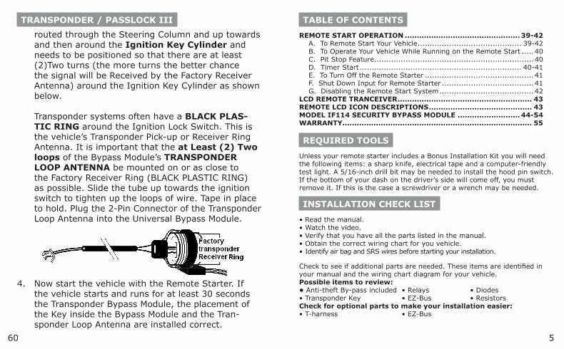
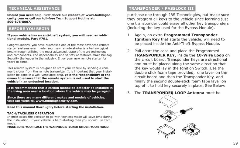
routed through the Steering Column and up towards and then around the Ignition Key Cylinder and needs to be positioned so that there are at least (2)Two turns (the more turns the better chance the signal will be Received by the Factory Receiver Antenna) around the Ignition Key Cylinder as shown below. Transponder systems often have a BLACK PLAS-TIC RING around the Ignition Lock Switch. This is the vehicle’s Transponder Pick-up or Receiver Ring Antenna. It is important that the at Least (2) Two loops of the Bypass Module’s TRANSPONDER LOOP ANTENNA be mounted on or as close to the Factory Receiver Ring (BLACK PLASTIC RING) as possible. Slide the tube up towards the ignition switch to tighten up the loops of wire. Tape in place to hold. Plug the 2-Pin Connector of the Transponder Loop Antenna into the Universal Bypass Module.
TRANSPONDER / PASSLOCK III
Now start the vehicle with the Remote Starter. If the vehicle starts and runs for at least 30 seconds the Transponder Bypass Module, the placement of the Key inside the Bypass Module and the Tran-sponder Loop Antenna are installed correct.
4.
TABLE OF CONTENTS
REMOTE START OPERATION ................................................ 39-42 A. To Remote Start Your Vehicle ........................................... 39-42 B. To Operate Your Vehicle While Running on the Remote Start ..... 40 C. Pit Stop Feature ..................................................................40 D. Timer Start ................................................................... 40-41 E. To Turn Off the Remote Starter .............................................41 F. Shut Down Input for Remote Starter ......................................41 G. Disabling the Remote Start System .......................................42LCD REMOTE TRANCEIVER ........................................................ 43REMOTE LCD ICON DESCRIPTIONS ........................................... 43MODEL IF114 SECURITY BYPASS MODULE ..........................44-54WARRANTY............................................................................... 55
REQUIRED TOOLS
Unless your remote starter includes a Bonus Installation Kit you will need the following items: a sharp knife, electrical tape and a computer-friendly test light. A 5/16-inch drill bit may be needed to install the hood pin switch. If the bottom of your dash on the driver’s side will come off, you must remove it. If this is the case a screwdriver or a wrench may be needed.
INSTALLATION CHECK LIST
• Read the manual. • Watch the video. • Verify that you have all the parts listed in the manual. • Obtain the correct wiring chart for you vehicle. • Identify air bag and SRS wires before starting your installation.
Check to see if additional parts are needed. These items are identified in your manual and the wiring chart diagram for your vehicle. Possible items to review: • Anti-theft By-pass included • Relays • Diodes • Transponder Key • EZ-Bus • Resistors Check for optional parts to make your installation easier: • T-harness • EZ-Bus
6
TRANSPONDER / PASSLOCK III
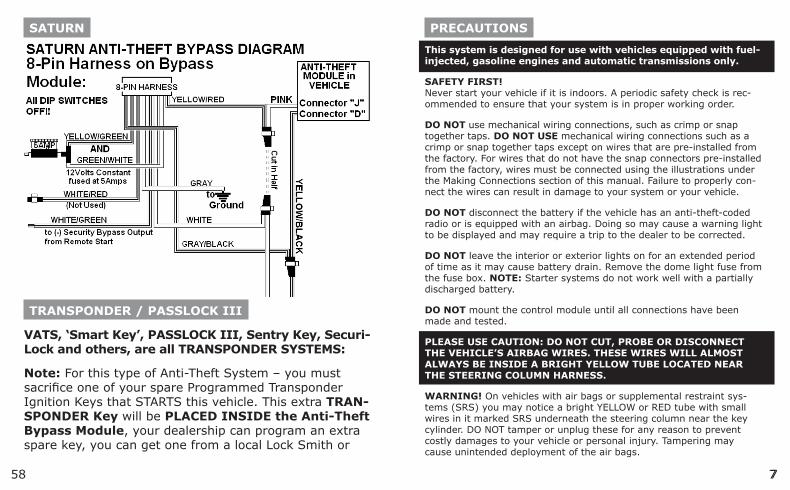
purchase one through JBS Technologies, but make sure they program all keys to the vehicle since learning just one transponder could erase all other key transponders (including the key used for the Bypass Module).
Again, an extra Programmed Transponder Ignition Key that starts the vehicle, will need to be placed inside the Anti-Theft Bypass Module.
Pull apart the case and place the Programmed TRANSPONDER KEY, inside the 10-Wire Loop on the circuit board. Transponder Keys are directional and must be placed along the same direction that the key would lay in the Ignition Switch. Use the double stick foam tape provided, one layer on the circuit board and then the Transponder Key, and finally the second double-stick foam tape layer on top of it to hold key securely in place, See Below:
The TRANSPONDER LOOP Antenna must be
1.
2.
3.
TECHNICAL ASSISTANCE
Should you need help. First check our website at www.bulldogse-curity.com or call our toll-free Tech Support Hotline at: 800-878-8007.
BEFORE YOU BEGIN
If your vehicle has an anti-theft system, you will need an addi-tional module, Part #791.
Congratulations, you have purchased one of the most advanced remote starter systems ever made. Your new remote starter is a technological breakthrough utilizing the most advanced, state of the art technology and components. The dependability and variety of features make Bulldog Security the leader in the industry. Enjoy your new remote starter for years to come!
This remote system is designed to start your vehicle by sending a com-mand signal from the remote transmitter. It is important that your instal-lation be done in a well-ventilated area. It is the responsibility of the owner to ensure that the remote system is not used to start the vehicle in an undesired location.
It is recommended that a carbon monoxide detector be installed in the living area near a location where the vehicle may be garaged.
Since there are many different makes and models of vehicles, visit our website, www.bulldogsecurity.com.
Read this manual thoroughly before starting the installation.
TACH/TACHLESS OPERATION In most cases the decision to go with tachless mode will save time during the installation. If your vehicle is hard-starting then you should use tach mode. MAKE SURE YOU PLACE THE WARNING STICKER UNDER YOUR HOOD.
59
7
SATURN
TRANSPONDER / PASSLOCK III
VATS, ‘Smart Key’, PASSLOCK III, Sentry Key, Securi-Lock and others, are all TRANSPONDER SYSTEMS:
Note: For this type of Anti-Theft System – you must sacrifice one of your spare Programmed Transponder Ignition Keys that STARTS this vehicle. This extra TRAN-SPONDER Key will be PLACED INSIDE the Anti-Theft Bypass Module, your dealership can program an extra spare key, you can get one from a local Lock Smith or
758
PRECAUTIONS
This system is designed for use with vehicles equipped with fuel-injected, gasoline engines and automatic transmissions only.
SAFETY FIRST! Never start your vehicle if it is indoors. A periodic safety check is rec-ommended to ensure that your system is in proper working order.
DO NOT use mechanical wiring connections, such as crimp or snap together taps. DO NOT USE mechanical wiring connections such as a crimp or snap together taps except on wires that are pre-installed from the factory. For wires that do not have the snap connectors pre-installed from the factory, wires must be connected using the illustrations under the Making Connections section of this manual. Failure to properly con-nect the wires can result in damage to your system or your vehicle.
DO NOT disconnect the battery if the vehicle has an anti-theft-coded radio or is equipped with an airbag. Doing so may cause a warning light to be displayed and may require a trip to the dealer to be corrected.
DO NOT leave the interior or exterior lights on for an extended period of time as it may cause battery drain. Remove the dome light fuse from the fuse box. NOTE: Starter systems do not work well with a partially discharged battery.
DO NOT mount the control module until all connections have been made and tested.
PLEASE USE CAUTION: DO NOT CUT, PROBE OR DISCONNECT THE VEHICLE’S AIRBAG WIRES. THESE WIRES WILL ALMOST ALWAYS BE INSIDE A BRIGHT YELLOW TUBE LOCATED NEAR THE STEERING COLUMN HARNESS.
WARNING! On vehicles with air bags or supplemental restraint sys-tems (SRS) you may notice a bright YELLOW or RED tube with small wires in it marked SRS underneath the steering column near the key cylinder. DO NOT tamper or unplug these for any reason to prevent costly damages to your vehicle or personal injury. Tampering may cause unintended deployment of the air bags.
578
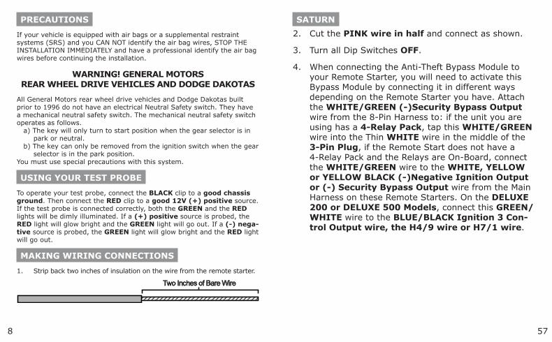
Cut the PINK wire in half and connect as shown.
Turn all Dip Switches OFF.
When connecting the Anti-Theft Bypass Module to your Remote Starter, you will need to activate this Bypass Module by connecting it in different ways depending on the Remote Starter you have. Attach the WHITE/GREEN (-)Security Bypass Output wire from the 8-Pin Harness to: if the unit you are using has a 4-Relay Pack, tap this WHITE/GREEN wire into the Thin WHITE wire in the middle of the 3-Pin Plug, if the Remote Start does not have a 4-Relay Pack and the Relays are On-Board, connect the WHITE/GREEN wire to the WHITE, YELLOW or YELLOW BLACK (-)Negative Ignition Output or (-) Security Bypass Output wire from the Main Harness on these Remote Starters. On the DELUXE 200 or DELUXE 500 Models, connect this GREEN/WHITE wire to the BLUE/BLACK Ignition 3 Con-trol Output wire, the H4/9 wire or H7/1 wire.
2.
3.
4.
SATURNPRECAUTIONS
If your vehicle is equipped with air bags or a supplemental restraint systems (SRS) and you CAN NOT identify the air bag wires, STOP THE INSTALLATION IMMEDIATELY and have a professional identify the air bag wires before continuing the installation.
WARNING! GENERAL MOTORS REAR WHEEL DRIVE VEHICLES AND DODGE DAKOTAS
All General Motors rear wheel drive vehicles and Dodge Dakotas built prior to 1996 do not have an electrical Neutral Safety switch. They have a mechanical neutral safety switch. The mechanical neutral safety switch operates as follows.
a) The key will only turn to start position when the gear selector is in park or neutral.
b) The key can only be removed from the ignition switch when the gear selector is in the park position.
You must use special precautions with this system.
USING YOUR TEST PROBE
To operate your test probe, connect the BLACK clip to a good chassis ground. Then connect the RED clip to a good 12V (+) positive source. If the test probe is connected correctly, both the GREEN and the RED lights will be dimly illuminated. If a (+) positive source is probed, the RED light will glow bright and the GREEN light will go out. If a (-) nega-tive source is probed, the GREEN light will glow bright and the RED light will go out.
MAKING WIRING CONNECTIONS
Strip back two inches of insulation on the wire from the remote starter.
1.
PASSLOCK II
9
SATURN
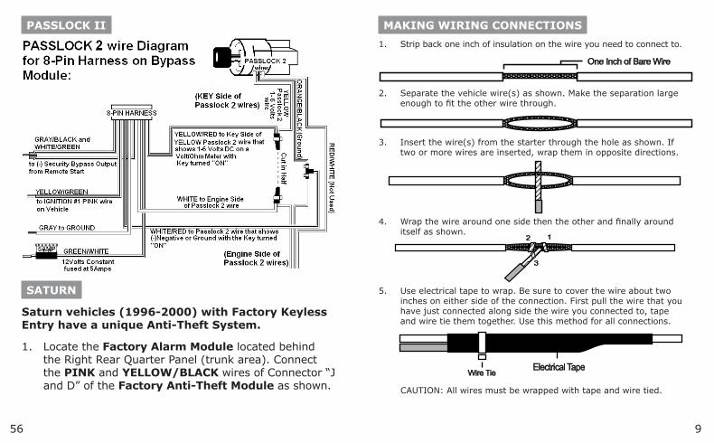
Saturn vehicles (1996-2000) with Factory Keyless Entry have a unique Anti-Theft System.
Locate the Factory Alarm Module located behind the Right Rear Quarter Panel (trunk area). Connect the PINK and YELLOW/BLACK wires of Connector “J and D” of the Factory Anti-Theft Module as shown.
1.
56
Strip back one inch of insulation on the wire you need to connect to.
Separate the vehicle wire(s) as shown. Make the separation large enough to fit the other wire through.
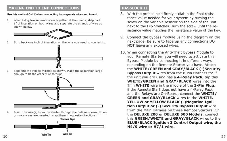
Insert the wire(s) from the starter through the hole as shown. If two or more wires are inserted, wrap them in opposite directions.
Wrap the wire around one side then the other and finally around itself as shown.
Use electrical tape to wrap. Be sure to cover the wire about two inches on either side of the connection. First pull the wire that you have just connected along side the wire you connected to, tape and wire tie them together. Use this method for all connections.
CAUTION: All wires must be wrapped with tape and wire tied.
1.
2.
3.
4.
5.
MAKING WIRING CONNECTIONS
10
With the probes held firmly – dial-in the final resis-tance value needed for your system by turning the screw on the variable resistor on the side of the unit next to the Dip Switches. Turn the screw until the re-sistance value matches the resistance value of the key.
Connect the bypass module using the diagram on the next page. Be sure to tape up any connections DO NOT leave any exposed wires.
When connecting the Anti-Theft Bypass Module to your Remote Starter, you will need to activate this Bypass Module by connecting it in different ways depending on the Remote Starter you have. Attach the WHITE/GREEN and GRAY/BLACK (-)Security Bypass Output wires from the 8-Pin Harness to: if the unit you are using has a 4-Relay Pack, tap this WHITE/GREEN and GRAY/BLACK wires into the Thin WHITE wire in the middle of the 3-Pin Plug, if the Remote Start does not have a 4-Relay Pack and the Relays are On-Board, connect the WHITE/GREEN and GRAY/BLACK wires to the WHITE, YELLOW or YELLOW BLACK (-)Negative Igni-tion Output or (-) Security Bypass Output wire from the Main Harness on these Remote Starters. On the DELUXE 200 or DELUXE 500 Models, connect this GREEN/WHITE and GRAY/BLACK wires to the BLUE/BLACK Ignition 3 Control Output wire, the H4/9 wire or H7/1 wire.
8.
9.
10.
PASSLOCK II
5510
MAKING END TO END CONNECTIONS
Use this method ONLY when connecting two separate wires end to end.
When tying two separate wires together at their ends, strip back 1” of insulation on both wires and separate the strands of wire as shown below.
Strip back one inch of insulation on the wire you need to connect to.
Separate the vehicle wire(s) as shown. Make the separation large enough to fit the other wire through.
Insert the wire(s) from the starter through the hole as shown. If two or more wires are inserted, wrap them in opposite directions.
1.
2.
3.
4.
1154
Turn the key to the “Run” position and place the vehicle in Reverse.
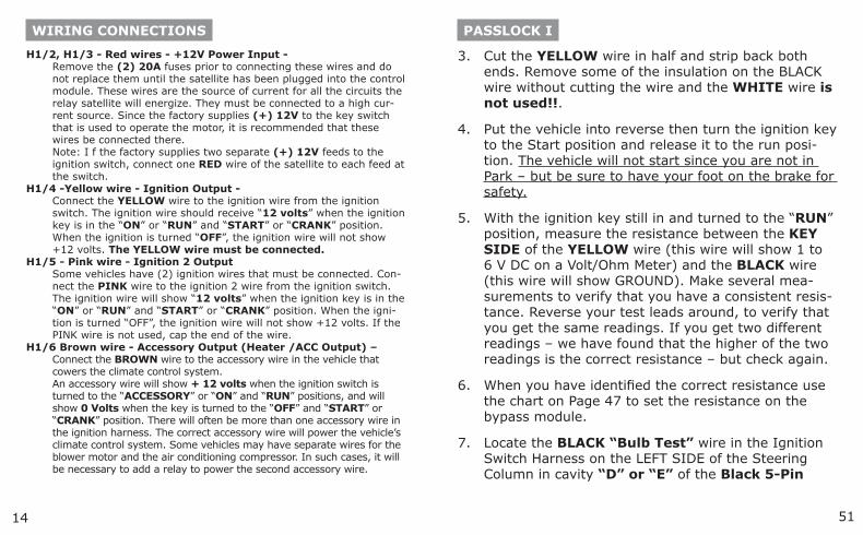
Turn the key to start, then release the key to the “run” position and measure the resistance between the KEY SIDE of the YELLOW wire (this wire will show 1 to 6 V DC on a Volt/Ohm Meter) and the ORANGE/BLACK wire or BLACK wire (this wire will show GROUND) the RED/WHITE wire is NOT USED!!. (The vehicle will not start since you are not in Park but be sure to have your foot on the brake for safety.) Reverse your test leads around, to verify that you get the same readings. If you get two dif-ferent readings – we have found that the higher of the two readings is the correct resistance – but check again.
When you have identified the correct resistance use the chart on Page 47 to set the resistance on the bypass module. Locate the closest value that is less than your desired value. Set Dip-Switches 2 through 6 to match the chart on Page 47.
Put your ohm meter (multi-meter) probes on the (2)Two silver resistance measuring pads through the opening shown in the drawing – making good con-tact with these (2)Two silver pads on the board. (See drawing on page 44). Or put your (2)Two probes into the (2)Two holes on the bottom of the case making contact with the underside of the silver pads. Either contact point method will work.
4.
5.
6.
7.
PASSLOCK II COMPONENTS
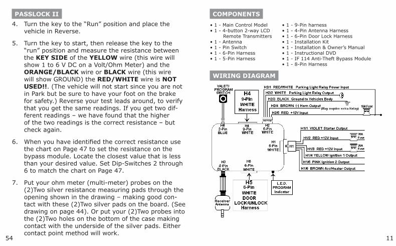
• 1 - Main Control Model • 1 - 9-Pin harness • 1 - 4-button 2-way LCD • 1 - 4-Pin Antenna Harness Remote Transmitters • 1 - 6-Pin Door Lock Harness • 1 - Antenna • 1 - Installation Kit • 1 - Pin Switch • 1 - Installation & Owner’s Manual • 1 - 6-Pin Harness • 1 - Instructional DVD • 1 - 5-Pin Harness • 1 - IF 114 Anti-Theft Bypass Module • 1 - 8-Pin Harness
WIRING DIAGRAM
5312
PASSLOCK I
PASSLOCK II
Remove the Lower Steering Column cover on the Steering Column.
Locate the (3)Three Small 20 Gauge wires (YEL-LOW, ORANGE/BLACK sometimes BLACK and RED/WHITE wires) coming out of the Ignition Key Cylinder of the Steering Column, these wires are usually wrapped in BLACK friction tape.
Cut the Yellow wire in half and strip back both ends. Remove the insulation on the Orange/Black wire with-out cutting the wire. The Red/White wire is not used.
1.
2.
3.
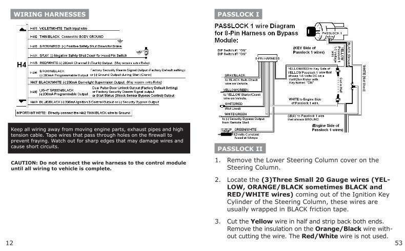
WIRING HARNESSES
Keep all wiring away from moving engine parts, exhaust pipes and high tension cable. Tape wires that pass through holes on the firewall to prevent fraying. Watch out for sharp edges that may damage wires and cause short circuits.
CAUTION: Do not connect the wire harness to the control module until all wiring to vehicle is complete.
1352
connector (between the Heavy Gauge RED and RED/WHITE wires), in the main Ignition Switch Harness. NOTE ** This is a different wire than the BLACK GROUND wire mentioned in the above steps.
Connect the Bypass module using the diagram be-low. Be sure to tape up any connections, DO NOT leave any exposed wires.
When connecting the Anti-Theft Bypass Module to your Remote Starter, you will need to activate this Bypass Module by connecting it in different ways depending on the Remote Starter you have. Attach the WHITE/GREEN (-)Security Bypass Output wire from the 8-Pin Harness to: if the unit you are using has a 4-Relay Pack, tap this WHITE/GREEN wire into the thin WHITE wire in the middle of the 3-Pin Plug, if the Remote Start does not have a 4-Relay Pack and the Relays are On-Board, connect the WHITE/GREEN wire to the WHITE, YELLOW or YELLOW BLACK (-)Negative Ignition Output or (-) Security Bypass Output wire from the Main Harness on these Remote Starters. On the DELUXE 200 or DELUXE 500 Models, connect this GREEN/WHITE wire to the BLUE/BLACK Ignition 3 Con-trol Output wire, the H4/9 wire or H7/1 wire.
8.
9.
PASSLOCK I WIRING CONNECTIONS
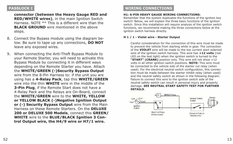
H1: 6-PIN HEAVY GAUGE WIRING CONNECTIONS: Remember that the system duplicates the functions of the ignition key switch! Below, we will explain the three basic functions of the ignition switch. Since this installation will require analysis of the ignition switch functions, we recommend making the three connections below at the ignition switch harness directly.
H 1 / 1 - Violet wire - Starter Output
Careful consideration for the connection of this wire must be made to prevent the vehicle from starting while in gear. The connection of the VIOLET wire will be made to the low current start solenoid wire of the ignition switch harness. This wire has +12 volts (red LED on the test light) when the ignition switch is turned to the “START” (CRANK) position only. This wire will not show +12 volts in all other ignition switch positions. NOTE: This wire must be connected to the vehicle side of the starter cut relay (when used). For the electrical neutral switch configuration, this connec-tion must be made between the starter inhibit relay (when used) and the neutral safety switch as shown in the following diagram. Failure to connect this wire to the ignition switch side of the neutral safety switch can result in personal injury and property damage. SEE NEUTRAL START SAFETY TEST FOR FURTHER DETAILS.
5114
PASSLOCK I
Cut the YELLOW wire in half and strip back both ends. Remove some of the insulation on the BLACK wire without cutting the wire and the WHITE wire is not used!!.
Put the vehicle into reverse then turn the ignition key to the Start position and release it to the run posi-tion. The vehicle will not start since you are not in Park – but be sure to have your foot on the brake for safety.
With the ignition key still in and turned to the “RUN” position, measure the resistance between the KEY SIDE of the YELLOW wire (this wire will show 1 to 6 V DC on a Volt/Ohm Meter) and the BLACK wire (this wire will show GROUND). Make several mea-surements to verify that you have a consistent resis-tance. Reverse your test leads around, to verify that you get the same readings. If you get two different readings – we have found that the higher of the two readings is the correct resistance – but check again.
When you have identified the correct resistance use the chart on Page 47 to set the resistance on the bypass module.
Locate the BLACK “Bulb Test” wire in the Ignition Switch Harness on the LEFT SIDE of the Steering Column in cavity “D” or “E” of the Black 5-Pin
3.
4.
5.
6.
7.
WIRING CONNECTIONS
H1/2, H1/3 - Red wires - +12V Power Input -Remove the (2) 20A fuses prior to connecting these wires and do not replace them until the satellite has been plugged into the control module. These wires are the source of current for all the circuits the relay satellite will energize. They must be connected to a high cur-rent source. Since the factory supplies (+) 12V to the key switch that is used to operate the motor, it is recommended that these wires be connected there. Note: I f the factory supplies two separate (+) 12V feeds to the ignition switch, connect one RED wire of the satellite to each feed at the switch.
H1/4 -Yellow wire - Ignition Output -Connect the YELLOW wire to the ignition wire from the ignition switch. The ignition wire should receive “12 volts” when the ignition key is in the “ON” or “RUN” and “START” or “CRANK” position. When the ignition is turned “OFF”, the ignition wire will not show +12 volts. The YELLOW wire must be connected.
H1/5 - Pink wire - Ignition 2 OutputSome vehicles have (2) ignition wires that must be connected. Con-nect the PINK wire to the ignition 2 wire from the ignition switch. The ignition wire will show “12 volts” when the ignition key is in the “ON” or “RUN” and “START” or “CRANK” position. When the igni-tion is turned “OFF”, the ignition wire will not show +12 volts. If the PINK wire is not used, cap the end of the wire.
H1/6 Brown wire - Accessory Output (Heater /ACC Output) –Connect the BROWN wire to the accessory wire in the vehicle that cowers the climate control system. An accessory wire will show + 12 volts when the ignition switch is turned to the “ACCESSORY” or “ON” and “RUN” positions, and will show 0 Volts when the key is turned to the “OFF” and “START” or “CRANK” position. There will often be more than one accessory wire in the ignition harness. The correct accessory wire will power the vehicle’s climate control system. Some vehicles may have separate wires for the blower motor and the air conditioning compressor. In such cases, it will be necessary to add a relay to power the second accessory wire.
1550
VATS
PASSLOCK I
Remove the Lower Steering Column cover on the Steering Column.
Locate the (3)Three small 20 Gauge wires (YEL-LOW, BLACK and WHITE wires in a GRAY or BLACK Plug) coming out of the Ignition Key Cyl-inder on the Bottom right hand side of the Steering Column.
1.
2.
WIRING CONNECTIONS
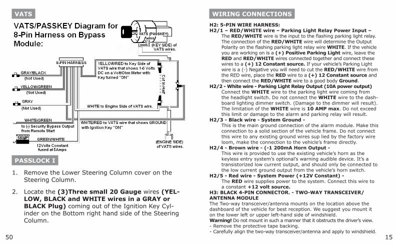
H2: 5-PIN WIRE HARNESS:H2/1 – RED/WHITE wire – Parking Light Relay Power Input –
The RED/WHITE wire is the input to the flashing parking light relay. The connection of the RED/WHITE wire will determine the Output Polarity on the flashing parking light relay wire WHITE. If the vehicle you are working on is a (+) Positive Parking Light wire, leave the RED and RED/WHITE wires connected together and connect these wires to a (+) 12 Constant source. If your vehicle’s Parking Light wire is a (-) Negative you will need to cut the RED/WHITE wire from the RED wire, place the RED wire to a (+) 12 Constant source and then connect the RED/WHITE wire to a good body Ground.
H2/2 - White wire - Parking Light Relay Output (10A power output)Connect the WHITE wire to the parking light wire coming from the headlight switch. Do not connect the WHITE wire to the dash-board lighting dimmer switch. (Damage to the dimmer will result). The limitation of the WHITE wire is 10 AMP max. Do not exceed this limit or damage to the alarm and parking relay will result.
H2/3 - Black wire - System Ground -This is the main ground connection of the alarm module. Make this connection to a solid section of the vehicle frame. Do not connect this wire to any existing ground wires sup lied by the factory wire loom, make the connection to the vehicle’s frame directly.
H2/4 - Brown wire - (-1 200mA Horn Output -This wire is provided to use the existing vehicle’s horn as the keyless entry system’s optional’s warning audible device. It’s a transistorized low current output, and should only be connected to the low current ground output from the vehicle’s horn switch.
H2/5 - Red wire - System Power (+12V Constant) -The RED wire supplies power to the system. Connect this wire to a constant +12 volt source.
H3: BLACK 4-PIN CONNECTOR. - TWO-WAY TRANSCEIVER/ ANTENNA MODULEThe Two-way transceiver/antenna mounts on the location above the dashboard of the vehicle for best reception. We suggest you mount it on the lower left or upper left-hand side of windshield.Warning! Do not mount in such a manner that it obstructs the driver’s view.- Remove the protective tape backing.- Carefully align the two-way transceiver/antenna and apply to windshield.
4916
VATS
WHITE or (1) WHITE/BLACK striped and (1)PURPLE/BLACK striped) 20 Gauge wires, these wires are often in a ORANGE or BLACK Plas-tic Tube. Be careful not to cut into the YELLOW Air Bag wires! The Air Bag wires are often in a YELLOW Plastic Tube that is clearly marked. The VATS wires run from the Ignition Switch down the Steering Column to the under side of the dash. Connect the Universal Bypass Module using the diagram on the next page.
When connecting the Anti-Theft Bypass Module to your Remote Starter, you will need to activate this Bypass Module by connecting it in different ways depending on the Remote Starter you have. Attach the WHITE/GREEN (-)Security Bypass Output wire from the 8-Pin Harness to: if the unit you are using has a 4-Relay Pack, tap this WHITE/GREEN wire into the Thin WHITE wire in the middle of the 3-Pin Plug, if the Remote Start does not have a 4-Relay Pack and the Relays are On-Board, connect the WHITE/GREEN wire to the WHITE, YELLOW or YELLOW BLACK (-)Negative Ignition Output or (-) Security Bypass Output wire from the Main Harness on these Remote Starters. On the DELUXE 200 or DELUXE 500 Models, connect this GREEN/WHITE wire to the BLUE/BLACK Ignition 3 Con-trol Output wire, the H4/9 wire or H7/1 wire.
6.
WIRING CONNECTIONS
- Route the black connector wire behind the trim and connect to the two-way transceiver/antenna.
- Connect the other end to the control module.- Special considerations must be made for windshield glass as some
newer vehicles utilize a metallic shielded window glass that will inhibit or restrict RF reception. In these vehicles, route the two-way transceiver/antenna module away from metallic shielded window glass as far as possible.
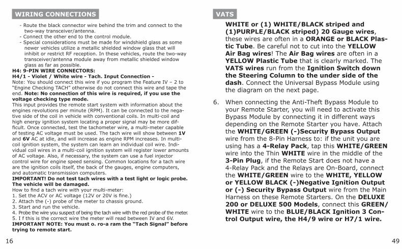
H4: 9-PIN WIRE CONNECTORS:H4/1 - Violet / White wire - Tach. Input Connection -Note: You should connect this wire if you program the Feature IV – 2 to “Engine Checking TACH” otherwise do not connect this wire and tape the end. Note: No connection of this wire is required, if you use the voltage checking type mode.This input provides the remote start system with information about the engines revolutions per minute (RPM). It can be connected to the nega-tive side of the coil in vehicle with conventional coils. In multi-coil and high energy ignition system locating a proper signal may be more dif-ficult. Once connected, test the tachometer wire, a multi-meter capable of testing AC voltage must be used. The tach wire will show between 1V and 6V AC at idle, and will increase as engine RPM increases. In multi-coil ignition system, the system can learn an individual coil wire. Indi-vidual coil wires in a multi-coil ignition system will register lower amounts of AC voltage. Also, if necessary, the system can use a fuel injector control wire for engine speed sensing. Common locations for a tach wire are the ignition coils itself, the back of the gauges, engine computers, and automatic transmission computers.IMPORTANT! Do not test tach wires with a test light or logic probe.The vehicle will be damaged.How to find a tach wire with your multi-meter:1. Set the ACV or AC voltage (12V or 20V is fine.)2. Attach the (-) probe of the meter to chassis ground.3. Start and run the vehicle.4. Probe the wire you suspect of being the tach wire with the red probe of the meter.5. I f this is the correct wire the meter will read between IV and 6V.IMPORTANT NOTE: You must o. ro-a ram the “Tach Signal” before trying to remote start.
1748
VATS
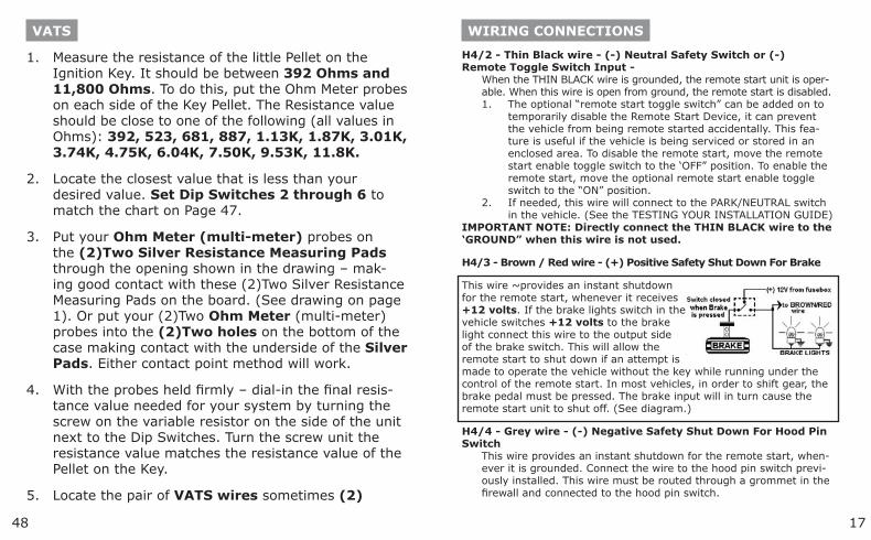
Measure the resistance of the little Pellet on the Ignition Key. It should be between 392 Ohms and 11,800 Ohms. To do this, put the Ohm Meter probes on each side of the Key Pellet. The Resistance value should be close to one of the following (all values in Ohms): 392, 523, 681, 887, 1.13K, 1.87K, 3.01K, 3.74K, 4.75K, 6.04K, 7.50K, 9.53K, 11.8K.
Locate the closest value that is less than your desired value. Set Dip Switches 2 through 6 to match the chart on Page 47.
Put your Ohm Meter (multi-meter) probes on the (2)Two Silver Resistance Measuring Pads through the opening shown in the drawing – mak-ing good contact with these (2)Two Silver Resistance Measuring Pads on the board. (See drawing on page 1). Or put your (2)Two Ohm Meter (multi-meter) probes into the (2)Two holes on the bottom of the case making contact with the underside of the Silver Pads. Either contact point method will work.
With the probes held firmly – dial-in the final resis-tance value needed for your system by turning the screw on the variable resistor on the side of the unit next to the Dip Switches. Turn the screw unit the resistance value matches the resistance value of the Pellet on the Key.
Locate the pair of VATS wires sometimes (2)
1.
2.
3.
4.
5.
WIRING CONNECTIONS
H4/2 - Thin Black wire - (-) Neutral Safety Switch or (-) Remote Toggle Switch Input -
When the THIN BLACK wire is grounded, the remote start unit is oper-able. When this wire is open from ground, the remote start is disabled.
The optional “remote start toggle switch” can be added on to temporarily disable the Remote Start Device, it can prevent the vehicle from being remote started accidentally. This fea-ture is useful if the vehicle is being serviced or stored in an enclosed area. To disable the remote start, move the remote start enable toggle switch to the ‘OFF” position. To enable the remote start, move the optional remote start enable toggle switch to the “ON” position.If needed, this wire will connect to the PARK/NEUTRAL switch in the vehicle. (See the TESTING YOUR INSTALLATION GUIDE)
IMPORTANT NOTE: Directly connect the THIN BLACK wire to the ‘GROUND” when this wire is not used.
H4/3 - Brown / Red wire - (+) Positive Safety Shut Down For Brake
This wire ~provides an instant shutdown for the remote start, whenever it receives +12 volts. If the brake lights switch in the vehicle switches +12 volts to the brake light connect this wire to the output side of the brake switch. This will allow the remote start to shut down if an attempt is made to operate the vehicle without the key while running under the control of the remote start. In most vehicles, in order to shift gear, the brake pedal must be pressed. The brake input will in turn cause the remote start unit to shut off. (See diagram.)
H4/4 - Grey wire - (-) Negative Safety Shut Down For Hood Pin Switch
This wire provides an instant shutdown for the remote start, when-ever it is grounded. Connect the wire to the hood pin switch previ-ously installed. This wire must be routed through a grommet in the firewall and connected to the hood pin switch.
1.
2.
4718
USE THIS CHART FOR VATS, PASSLOCK I & PASSLOCK II
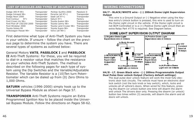
1 - 8-Pin HarnessDip Switch # 2 3 4 5 6Resistor Value 0.825 1.65 3.32 6.65 13.3 Final Resistance (k ohms) ON ON ON ON ON 0.000 +Trimpot Value OFF ON ON ON ON 0.825 +Trimpot Value ON OFF ON ON ON 1.650 +Trimpot Value OFF OFF ON ON ON 2.475 +Trimpot Value ON ON OFF ON ON 3.320 +Trimpot Value OFF ON OFF ON ON 4.145 +Trimpot Value ON OFF ON ON ON 4.970 +Trimpot Value OFF OFF OFF ON ON 5.795 +Trimpot Value ON ON ON OFF ON 6.650 +Trimpot Value OFF ON ON OFF ON 7.475 +Trimpot Value ON OFF ON OFF ON 8.300 +Trimpot Value OFF OFF ON OFF ON 9.125 +Trimpot Value ON ON OFF OFF ON 9.970 +Trimpot Value OFF ON OFF OFF ON 10.795 +Trimpot Value ON OFF OFF OFF ON 11.620 +Trimpot Value OFF OFF OFF OFF ON 12.445 +Trimpot Value ON ON ON ON OFF 13.300 +Trimpot Value OFF ON ON ON OFF 14.125 +Trimpot Value ON OFF ON ON OFF 14.950 +Trimpot Value OFF OFF ON ON OFF 15.775 +Trimpot Value ON ON OFF ON OFF 16.620 +Trimpot Value OFF ON OFF ON OFF 17.445 +Trimpot Value ON OFF OFF ON OFF 18.270 +Trimpot Value OFF OFF OFF ON OFF 19.095 +Trimpot Value ON ON ON OFF OFF 19.950 +Trimpot Value OFF ON ON OFF OFF 20.775 +Trimpot Value ON OFF ON OFF OFF 21.600 +Trimpot Value OFF OFF ON OFF OFF 22.425 +Trimpot Value ON ON OFF OFF OFF 23.270 +Trimpot Value OFF ON OFF OFF OFF 24.095 +Trimpot Value ON OFF OFF OFF OFF 24.920 +Trimpot Value OFF OFF OFF OFF OFF 25.745 +Trimpot Value All resistor values shown are in ‘K-Ohms’ or 1,000 Ohms. Thus the 1.650 value shown in the (3) Third row is 1,650 Ohms or 1.65K Ohms. Dip Switch #1 Dip Switch #7 VATS OFF OFFPASSLOCK I ON ONPASSLOCK II OFF OFF
WIRING CONNECTIONS
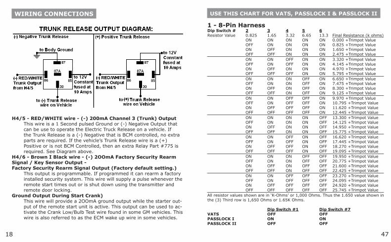
H4/5 - RED/WHITE wire - (-) 200mA Channel 3 (Trunk) Output
This wire is a 1 Second pulsed Ground or (-) Negative Output that can be use to operate the Electric Truck Release on a vehicle. If the Trunk Release is a (-) Negative that is BCM controlled, no extra parts are required. If the vehicle’s Trunk Release wire is a (+) Positive or is not BCM Controlled, then an extra Relay Part #775 is required. See Diagram above.
H4/6 - Brown I Black wire - (-) 2OOmA Factory Security Rearm Signal / Key Sensor Output -Factory Security Rearm Signal Output (Factory default setting.)
This output is programmable. If programmed it can rearm a factory installed security system. This wire will supply a pulse whenever the remote start times out or is shut down using the transmitter and remote door locking.
Ground Output During Start Crank)This wire will provide a 2OOmA ground output while the starter out-put of the remote start unit is active. This output can be used to ac-tivate the Crank Low/Bulb Test wire found in some GM vehicles. This wire is also referred to as the ECM wake up wire in some vehicles.
1946
LIST OF VEHICLES AND TYPES OF SECURITY SYSTEMS
Dodge 300 M 99+ Transponder Pontiac Sunfire 2000 Passlock IIDodge Intrepid 98+ Transponder Porsche (all 97+) TransponderDodge Neon 2000 Transponder Saab (all 97+) TransponderFord Contour 97+ Transponder Saturn 97+ FactoryFord Crown Vic 96+ Transponder Toyota Avalon 98+ TransponderFord Pick-UP 150/250 2000 Transponder Toyota Camry 98+ TransponderFord Windstar 2000 Transponder Toyota Land Cruiser 98+ TransponderToyota Solara 99 Transponder Toyota Supra 98+ TransponderVolkswagon Passat 98+ Transponder Volvo (all 98+) Transponder
First determine what type of Anti-Theft System you have in your vehicle. If unsure – follow the chart on the previ-ous page to determine the system you have. There are several types of systems as outlined below:
General Motors VATS, PASSLOCK I and PASSLOCK II Anti-Theft Systems: For these, you will be required to dial-in a resistor value that matches the resistance on your vehicles Anti-Theft System. The method is described on the following pages for each type of sys-tem using the Dip Switches and the Variable/Adjustable Resistor. The Variable Resistor is a (10)Ten turn Poten-tiometer which can be dialed up from (0) Zero Ohms to 1,000 Ohms.
SATURN vehicles (1996-2000) simply hook up to the Universal Bypass Module as shown on Page 57.
TRANSPONDER Anti-Theft Systems require an Extra Programmed Ignition Key to be placed inside the Univer-sal Bypass Module. Follow the directions on Pages 58-62.
WIRING CONNECTIONS
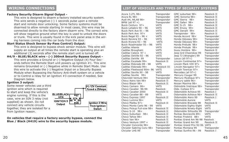
H4/7 - BLACK/WHITE wire - (-) 200mA Dome Light Supervision Output
This wire is a Ground Output or (-) Negative when using the Key-less entry’s Unlock button is pressed, this wire is used to turn on the Dome Light circuit in the vehicle. If the Dome Light circuit is not BCM Controlled or is a (+) Positive Dome Light circuit then an extra Relay Part #775 is required. See Diagram below.
H4/8 - LT. Green Black wire - (-) 200ma Programmable OutputDual Pulse Door unlock Output (Factory default settings)
The dual pulse door unlock feature will work the most fully elec-tronic door lock circuits. The vehicle must have an electronic door lock switch (not the lock knob or key switch), which, locks and unlocks all of vehicle’s doors. When wired for this feature, press-ing the disarm (or unlock button one time will disarm the alarm and unlock The drivers door only. Pressing the disarm (or unlock) button two times within (3) seconds, will disarm the alarm and all doors will unlock.
4520
LIST OF VEHICLES AND TYPES OF SECURITY SYSTEMS
Acura 3.2TL 98+ Transponder GMC suburban 98+ Passlock IIAcura RL 98+ Transponder GMC Sonoma 98+ Passlock IIAudi A4, A6,A8 98+ Transponder GMC Sierra 98+ Passlock IIBMW (all 97 +) Transponder GMC Safari 98+ Passlock IIBuick Century 97+ VATS GMC S-15 98+ Passlock IIBuick LeSabre 90 – 96 VATS GMC Envoy 99+ Passlock II Buick Park Ave 91 – 96 VATS GMC Denalli 99+ Passlock IIBuick Park Ave 97+ VATS Transponder 98+ Passlock IIBuick Regal 93 – 96 + VATS Honda Accord 98+ TransponderBuick Reviera 93 – 96 VATS Honda Odyssey 98+ TransponderBuick Riviera 93 – 96 VATS Honda Odyssey 98+ TransponderBuick Roadmaster 93 – 96 VATS Honda Prelude 98+ TransponderCadillac Allante VATS Honda Prelude 98+ TransponderCadillac Brougham VATS Isuzu Hombre 98+ Passlock IICadillac Catera 97 + VATS Jeep Grd Cheerokee 99 TransponderCadillac DeVille 92 - 96 VATS Jeep TJ (Wrangler) 99 TransponderCadillac DeVille 99 Transponder Lexus (all 97+) TransponderCadillac Escalade 99+ Passlock II Lincoln Continental 97+ TransponderCadillac Eldorado 89 - 98 VATS Lincoln Mark VIII 97+ TransponderCadillac Eldorado 99+ Passlock III Lincoln Navigator 97+ TransponderCadillac Fleetwood 90m- 96 VATS Lincoln Towncar 97+ TransponderCadillac Seville 90 - 98 VATS Mercedes (all 97+) TransponderCadillac Seville 99+ Transponder Mercury Cougar 99 TransponderChevrolet Venture 99+ Transponder Mercury Mystique 97+ TransponderChevy Astro Van 98+ Passlock II Mercury sable 96+ TransponderChevy Blazer 98+ Passlock II Nissan Maxima 98+ TransponderChevy Camaro 86+ VATS Oldmobile Instrique 98+ TransponderChevy Cavalier 96-99 Passlock Olds. Cutlass 97+ TransponderChevy Cavalier 2000 Passlock II Oldsmobile Achieva 95 Passlock IChevy Cavalier 88 - 89 VATS Oldsmobile Achieva 96+ Passlock IIChevy Express 1997 Passlock II Oldsmobile Alero 99 Passlock IChevy Lumina 96+ VATS Oldsmobile Aurora VATSChevy Malibu 97+ Passlock II Oldsmobile Bravada 98 Passlock IIChevy Monte Carlo 96 - 99 VATS Oldsmobile Eighty-Eight VATSChevy Pickup Full-size 98+ Passlock II Oldsmobile Ninety-Eight VATS Chevy S-10 98+ Passlock II Oldsmobile Silhoutte 99 TransponderChevy Suburban 98+ Passlock II Pontiac Bonneville 89+ VATSChevy Tahoe 98+ Passlock II Pontiac Firebird 88+ VATSChevy Van 96+ Passlock II Pontiac Grand Am 96-98 PasslockChevy Venture 1997 + Passlock II Pontiac Grand Am 99 Passlock IIChrysler Concorde 98+ Transponder Pontiac Grand Prix 92-96 VATSChrysler Sabring Conv 98+ Transponder Pontiac Montana 99 TransponderChrysler LHS 99 Transponder Pontiac Sunfire 96 - 99 Passlock I
WIRING CONNECTIONS
Factory Security Disarm Signal Output -This wire is designed to disarm a factory installed security system. This wire sends a negative (-) 1 seconds pulse upon a remote start and remote door unlocking. Some factory systems must be disarmed to allow remote starting In most cases, this wire may be connected directly to the factory alarm disarm wire. The correct wire will show negative ground when the key is used to unlock the doors or trunk. This wire is usually found in the kick panel area in the wir-ing harness coming into the car body from the door.
Start Status Shock Sensor By-Pass Control) Output:This wire is designed to bypass shock sensor module. This wire will supply an output at all times the remote start is operating plus an additional (3) seconds after the remote start unit is turned off.
H4/9 - BLUE/BLACK wire - (-) 200mA Security Bypass Output -This wire provides a Ground or (-) Negative Output (4) Four Sec-onds before the Remote Start unit powers up Ignition #1. This wire remains Grounded or (-) Negative while in Remote Start Mode. Use this wire to activate the (-) Negative Input on a Security Bypass Module when Bypassing the Factory Anti-theft system on a vehicle or to Control a relay for an Ignition #3 connection if needed, See Diagram below.
Ignition 3 output:Some newer vehicles use a third ignition wire which is required to start and keep the vehicle’s engine running. If this is the case, wire an IGN 3 relay (not supplied) as shown. Do not connect any vehicle circuits together, they are isolated for a from Ignition reason. On vehicles that require a factory security bypass, connect the Blue / Black (H419) wire to the security bypass module.
2144
MODEL IF114VATS/PASSLOCK/TRANSPONDER
UNIVERSAL ALARM BYPASS MODULE
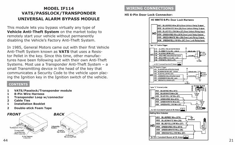
This module lets you bypass virtually any type of Vehicle Anti-Theft System on the market today to remotely start your vehicle without permanently disabling the Vehicle’s Factory Anti-Theft System.
In 1985, General Motors came out with their first Vehicle Anti-Theft System known as VATS that uses a Resis-tor Pellet in the key. Since this time, other manufac-tures have been following suit with their own Anti-Theft Systems. Most use a Transponder Anti-Theft System – a small Transmitting device in the head of the key that communicates a Security Code to the vehicle upon plac-ing the Ignition key in the Ignition switch of the vehicle.
CONTENTS
1 VATS/Passlock/Transponder module 1 8-Pin Wire Harness 1 Transponder Loop w/connector 2 Cable Ties 1 Installation Booklet
2 Double-stick Foam Tape
FRONT BACK
WIRING CONNECTIONS
H5 6-Pin Door Lock Connector:
4322
WIRING CONNECTIONS
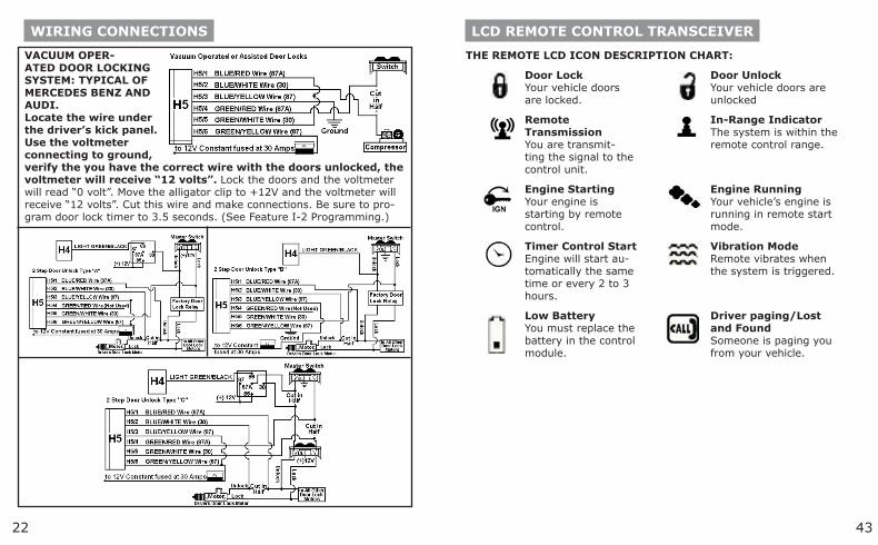
VACUUM OPER-ATED DOOR LOCKING SYSTEM: TYPICAL OF MERCEDES BENZ AND AUDI.Locate the wire under the driver’s kick panel. Use the voltmeter connecting to ground, verify the you have the correct wire with the doors unlocked, the voltmeter will receive “12 volts”. Lock the doors and the voltmeter will read “0 volt”. Move the alligator clip to +12V and the voltmeter will receive “12 volts”. Cut this wire and make connections. Be sure to pro-gram door lock timer to 3.5 seconds. (See Feature I-2 Programming.)
LCD REMOTE CONTROL TRANSCEIVER
THE REMOTE LCD ICON DESCRIPTION CHART:
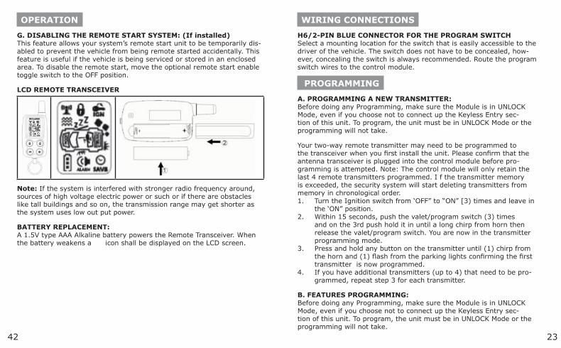
Door LockYour vehicle doors are locked.
Door UnlockYour vehicle doors are unlocked
Remote TransmissionYou are transmit-ting the signal to the control unit.
In-Range IndicatorThe system is within the remote control range.
Engine StartingYour engine is starting by remote control.
Engine RunningYour vehicle’s engine is running in remote start mode.
Timer Control StartEngine will start au-tomatically the same time or every 2 to 3 hours.
Vibration ModeRemote vibrates when the system is triggered.
Low BatteryYou must replace the battery in the control module.
Driver paging/Lost and FoundSomeone is paging you from your vehicle.
2342
WIRING CONNECTIONS
H6/2-PIN BLUE CONNECTOR FOR THE PROGRAM SWITCHSelect a mounting location for the switch that is easily accessible to the driver of the vehicle. The switch does not have to be concealed, how-ever, concealing the switch is always recommended. Route the program switch wires to the control module.
PROGRAMMING
A. PROGRAMMING A NEW TRANSMITTER:Before doing any Programming, make sure the Module is in UNLOCK Mode, even if you choose not to connect up the Keyless Entry sec-tion of this unit. To program, the unit must be in UNLOCK Mode or the programming will not take.
Your two-way remote transmitter may need to be programmed to the transceiver when you first install the unit. Please confirm that the antenna transceiver is plugged into the control module before pro-gramming is attempted. Note: The control module will only retain the last 4 remote transmitters programmed. I f the transmitter memory is exceeded, the security system will start deleting transmitters from memory in chronological order.
Turn the Ignition switch from ‘OFF” to “ON” [3) times and leave in the ‘ON” position.Within 15 seconds, push the valet/program switch (3) times and on the 3rd push hold it in until a long chirp from horn then release the valet/program switch. You are now in the transmitter programming mode.Press and hold any button on the transmitter until (1) chirp from the horn and (1) flash from the parking lights confirming the first transmitter is now programmed.If you have additional transmitters (up to 4) that need to be pro-grammed, repeat step 3 for each transmitter.
B. FEATURES PROGRAMMING:Before doing any Programming, make sure the Module is in UNLOCK Mode, even if you choose not to connect up the Keyless Entry sec-tion of this unit. To program, the unit must be in UNLOCK Mode or the programming will not take.
1.
2.
3.
4.
OPERATION
G. DISABLING THE REMOTE START SYSTEM: (If installed)This feature allows your system’s remote start unit to be temporarily dis-abled to prevent the vehicle from being remote started accidentally. This feature is useful if the vehicle is being serviced or stored in an enclosed area. To disable the remote start, move the optional remote start enable toggle switch to the OFF position.
LCD REMOTE TRANSCEIVER
Note: If the system is interfered with stronger radio frequency around, sources of high voltage electric power or such or if there are obstacles like tall buildings and so on, the transmission range may get shorter as the system uses low out put power.
BATTERY REPLACEMENT:A 1.5V type AAA Alkaline battery powers the Remote Transceiver. When the battery weakens a icon shall be displayed on the LCD screen.
4124
PROGRAMMINGALARM FEATURE. #1 PROGRAMMING:
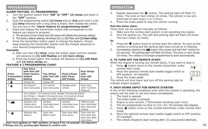
Turn the Ignition switch from “ON” to “OFF” (3) times and leave in the “OFF” position.Push the programming switch (2) times and on 2nd push hold it until (1) chirp followed with a long chirp is heard, then release the switch. You are now in the “alarm feature #1 programming mode”.Press and release the transmitter button that corresponds to the feature you desire to program. a. The amount of horn chirps and LED pause will indicate the previous setting. b. The factory default settings will always be (1) LED flash and (1) horn chirp.Press the transmitter button again to change the feature. Simply keep pressing the transmitter button until the module advances to vour desired programming setting.
Example:a. After you hear (1) chirp, press the button again and the module
will advance to (2) LED flashes and (2) horn chirps.b. Press the button again, the module will advance to (3) LED flash
and (3) horn chirps etc.FEATURE # I PROGRAMMING CHART
Press Transmitter Button
One Chirp with One LED Pulse Factory Default Setting
Two Chirps with Two LED Pulses
Three Chirps with Three LED Pulses
Four Chirps with Four LED Pulses
1 Chirps On Chirps Off
2 0.8 second door lock pulse
3.5 second door lock pulse
Double pulse unlock
Door lock with “Comfort Feature”
Five Chirps = 0.8 second Lock, double 0.8 second Unlock Six Chirps = Double 0.8 second Lock, 0.8 second Unlock Seven Chirps = Door lock with “Comfort Feature”
3 Ignition con-trolled door lock and unlock
Ignition controlled door locks only
Ignition controlled door unlock only
Without igni-tion controlled door lock and unlock
4 Without this feature
Door lock Before start
Door lock after shut down
Door lock be-fore start and door lock after shut down
Exit: Turn Ignition to “ON” position, or leave it for 15 seconds. (3) long horn chirps and (3) parking light flashes to confirm exit.
1.
2.
3.
4.
OPERATION
Rapidly depresses the button. The parking light will flash (3) times. The siren or horn chirps (3) times. The vehicle is now pro-grammed to start every 2 or 3 hours.Press the brake pedal to stop the vehicle running.
Exit the timer start:Timer start can be exited manually as follows:
Make sure the remote start system is not operating the engine.Turn the ignition on. The LED and parking light will flash (4) times.The horn chirps (4) times.
OrPress the button twice to remote start the vehicle. As soon as the vehicle is running and the parking light have turned on or flashing.Immediately depress the button then press and hold the* button for (2) seconds. The parking light will flash (4) times. The siren or horn chirps (4) times. The vehicle is no longer programmed to start automatically.
E. TO TURN OFF THE REMOTE START:When the engine is running (by remote start), if you want to stop it,
Press button twice on the remote transmitter under remote start mode.Move the optional remote start enable toggle switch to OFF position. (If installed)Press the brake pedal.
The vehicle will shut down and turn off the parking light to indicate engine stopped.
F. SHUT-DOWN INPUT FOR REMOTE STARTER:If any of the following conditions exist while the system is operating, the engine will not start or will shut down immediately:
The hood is opened.The brake pedal is pressed.Engine is over-revved. (“Tachometer checking type” only)The pre-programmed run time (5 110 / 20 / 30 minutes) has elapsed.Press button twice on the remote transmitter under remote start mode.Move the optional remote start enable toggle switch to OFF position. (If installed)The vehicle refused to start running after (3) unsuccessful attempts.
3.
4.
1.2.
1.
2.
1.
2.
3.
1.2.3.4.5.
6.
7.
2540
PROGRAMMING
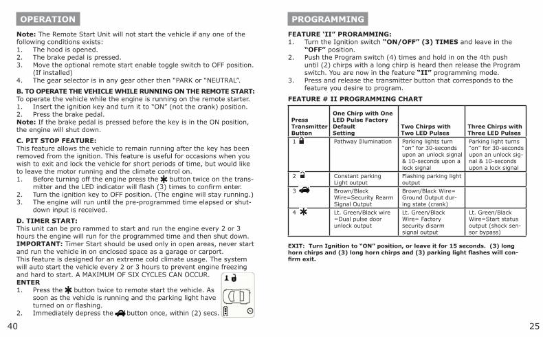
FEATURE ‘II” PRORAMMING:Turn the Ignition switch “ON/OFF” (3) TIMES and leave in the “OFF” position.Push the Program switch (4) times and hold in on the 4th push until (2) chirps with a long chirp is heard then release the Program switch. You are now in the feature “II” programming mode.Press and release the transmitter button that corresponds to the feature you desire to program.
FEATURE # II PROGRAMMING CHART
Press Transmitter Button
One Chirp with One LED Pulse Factory Default Setting
Two Chirps with Two LED Pulses
Three Chirps with Three LED Pulses
1 Pathway Illumination Parking lights turn “on” for 30-seconds upon an unlock signal & 10-seconds upon a lock signal
Parking light turns “on” for 30-seconds upon an unlock sig-nal & 10-seconds upon a lock signal
2 Constant parking Light output
Flashing parking light output
3 Brown/Black Wire=Security Rearm Signal Output
Brown/Black Wire= Ground Output dur-ing state (crank)
4 Lt. Green/Black wire =Dual pulse door unlock output
Lt. Green/Black Wire= Factory security disarm signal output
Lt. Green/Black Wire=Start status output (shock sen-sor bypass)
EXIT: Turn Ignition to “ON” position, or leave it for 15 seconds. (3) long horn chirps and (3) long horn chirps and (3) parking light flashes will con-firm exit.
1.
2.
3.
OPERATION
Note: The Remote Start Unit will not start the vehicle if any one of the following conditions exists:
The hood is opened.The brake pedal is pressed.Move the optional remote start enable toggle switch to OFF position. (If installed)The gear selector is in any gear other then “PARK or “NEUTRAL”.
B. TO OPERATE THE VEHICLE WHILE RUNNING ON THE REMOTE START:To operate the vehicle while the engine is running on the remote starter.
Insert the ignition key and turn it to “ON” (not the crank) position.Press the brake pedal.
Note: If the brake pedal is pressed before the key is in the ON position, the engine will shut down.
C. PIT STOP FEATURE:This feature allows the vehicle to remain running after the key has been removed from the ignition. This feature is useful for occasions when you wish to exit and lock the vehicle for short periods of time, but would like to leave the motor running and the climate control on.
Before turning off the engine press the button twice on the trans-mitter and the LED indicator will flash (3) times to confirm enter.Turn the ignition key to OFF position. (The engine will stay running.)The engine will run until the pre-programmed time elapsed or shut-down input is received.
D. TIMER START:This unit can be pro rammed to start and run the engine every 2 or 3 hours the engine will run for the programmed time and then shut down.IMPORTANT: Timer Start should be used only in open areas, never start and run the vehicle in on enclosed space as a garage or carport.This feature is designed for an extreme cold climate usage. The system will auto start the vehicle every 2 or 3 hours to prevent engine freezing and hard to start. A MAXIMUM OF SIX CYCLES CAN OCCUR.ENTER
Press the button twice to remote start the vehicle. As soon as the vehicle is running and the parking light have turned on or flashing.Immediately depress the button once, within (2) secs.
1.2.3.
4.
1.2.
1.
2.3.
1.
2.
3926
PROGRAMMING
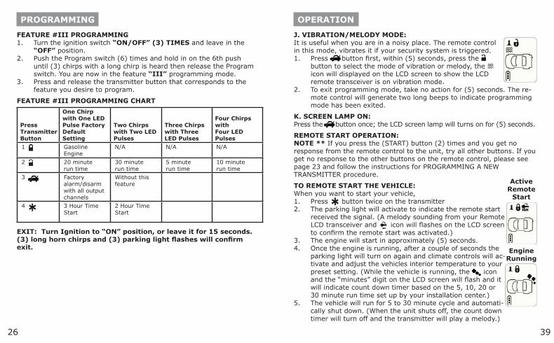
FEATURE #III PROGRAMMING Turn the ignition switch “ON/OFF” (3) TIMES and leave in the “OFF” position.Push the Program switch (6) times and hold in on the 6th push until (3) chirps with a long chirp is heard then release the Program switch. You are now in the feature “III” programming mode.Press and release the transmitter button that corresponds to the feature you desire to program.
FEATURE #III PROGRAMMING CHART
Press Transmitter Button
One Chirp with One LED Pulse Factory Default Setting
Two Chirps with Two LED Pulses
Three Chirps with Three LED Pulses
Four Chirps with Four LED Pulses
1 Gasoline Engine
N/A N/A N/A
2 20 minute run time
30 minute run time
5 minute run time
10 minute run time
3 Factory alarm/disarm with all output channels
Without this feature
4 3 Hour Time Start
2 Hour Time Start
EXIT: Turn Ignition to “ON” position, or leave it for 15 seconds. (3) long horn chirps and (3) parking light flashes will confirm exit.
1.
2.
3.
OPERATION
J. VIBRATION/MELODY MODE:It is useful when you are in a noisy place. The remote control in this mode, vibrates it if your security system is triggered.
Press button first, within (5) seconds, press the button to select the mode of vibration or melody, the icon will displayed on the LCD screen to show the LCD remote transceiver is on vibration mode.To exit programming mode, take no action for (5) seconds. The re-mote control will generate two long beeps to indicate programming mode has been exited.
K. SCREEN LAMP ON:Press the button once; the LCD screen lamp will turns on for (5) seconds.
REMOTE START OPERATION:NOTE ** If you press the (START) button (2) times and you get no response from the remote control to the unit, try all other buttons. If you get no response to the other buttons on the remote control, please see page 23 and follow the instructions for PROGRAMMING A NEW TRANSMITTER procedure.
TO REMOTE START THE VEHICLE:When you want to start your vehicle,
Press button twice on the transmitterThe parking light will activate to indicate the remote start received the signal. (A melody sounding from your Remote LCD transceiver and icon will flashes on the LCD screen to confirm the remote start was activated.)The engine will start in approximately (5) seconds.Once the engine is running, after a couple of seconds the parking light will turn on again and climate controls will ac-tivate and adjust the vehicles interior temperature to your preset setting. (While the vehicle is running, the icon and the “minutes” digit on the LCD screen will flash and it will indicate count down timer based on the 5, 10, 20 or 30 minute run time set up by your installation center.)The vehicle will run for 5 to 30 minute cycle and automati-cally shut down. (When the unit shuts off, the count down timer will turn off and the transmitter will play a melody.)
1.
2.
1.2.
3.4.
5.
Active Remote
Start
Engine Running
2738
PROGRAMMING
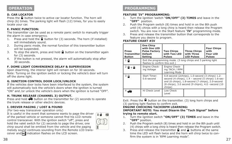
FEATURE ‘IV” PROGRAMMING:Turn the Ignition ‘switch “ON/OFF” (3) TIMES and leave in the “OFF” position.Push the Program switch (8) times and hold in on the 8th push until (4) chirps with a long chirp is heard then release the Program switch. You are now in the Start feature “IV” programming mode.Press and release the transmitter button that corresponds to the feature you desire to program.
FEATURE CHART #IV
Press Transmitter Button
One Chirp with One LED Pulse Factory Default Setting
Two Chirps with Two LED Pulses
Three Chirps with Three LED Pulses
Four Chirps with Four LED Pulses
1 Exit the programming mode. (3 long chirps and 3 parking light flashes to confirm this exit.)
2 Engine Check-ing Voltage
Engine Check-ing TACH / RPM Learning Mode
3 Start Timer: 0.6-second
0.8-second (2chirps), 1.0-second (3 chirps) 1.2-second (4 chirps), 1.4 – second (5 chirps) 1.6-sec-ond (6 chirps), 1.8-second (7 chirps), 2.0-second (8 chirps), 3.0 second (9 chiprs), 4.0 –second (10 chirps)
4 Hi Check Level Low Check Level
Exit: Press the button on the transmitter. (3) long horn chirps and (3) parking light flashes to confirm exit.ENGINE CHECKING TACHIRPM LEARNING:IMPORTANT NOTE: You must Disarm the “Tach Signal” before trying to remote start.
Turn the Ignition switch “ON/OFF” (3) TIMES and leave in the “OFF” position.Push the Program switch (8) times and hold in on the 8th push until (4) chirps with a long chirp is heard then release the Program switch.Press and release the transmitter and buttons at the same time the LED will flash twice and the horn will chirp twice to con-firm the system is in ‘RPM Learning mode”.
1.
2.
3.
1.
2.
3.
+
OPERATION
D. CAR LOCATORPress the button twice to active car locator function. The horn will chirp (6) times. The parking light will flash (12) times, for you to easily locate your car.
E. PANIC FUNCTION:The transmitter can be used as a remote panic switch to manually trigger the alarm in case emergency.
Press and hold the button for (3) seconds. The horn (if installed) will immediately sound.During panic mode, the normal function of this transmitter button will be suspended.To stop the alarm, press and hold button on the transmitter again for (3) seconds.If the button is not pressed, the alarm will automatically stop after 30 seconds.
F. DOME LIGHT CONVENIENCE DELAY & SUPERVISIONUpon disarming, the interior light will remain on for 30 seconds.Note: Turning on the ignition switch or locking the vehicle’s door will turn off the dome light.
G. IGNITION CONTROL DOOR LOCK/UNLOCKIf the vehicles door locks have been interfaced to the system, the system will automatically lock the vehicle’s doors when the ignition is turned “ON” and /or unlock the vehicle’s doors when the ignition is turned “OFF”.
H. TRUNK RELEASE (CHANNEL 3) OUTPUT.Press and hold button on the transmitter for (2) seconds to operate the trunk release or other electric devices.
I. DRIVER PAGING / LOST & FOUND(For two-way transceiver operation only)It is useful in the event that someone wants to page the driver of the parked vehicle or someone cannot find his LCD remote control transceiver. With the ignition switch “off”, press and hold the valet switch for (2) seconds to page the driver, one chirp sound shall be emitted from the vehicle and the paging melody sound continues sounding from the Remote LCD trans-ceiver and indication flashes on the LCD screen.
1.
2.
3.
4.
3728
PROGRAMMING
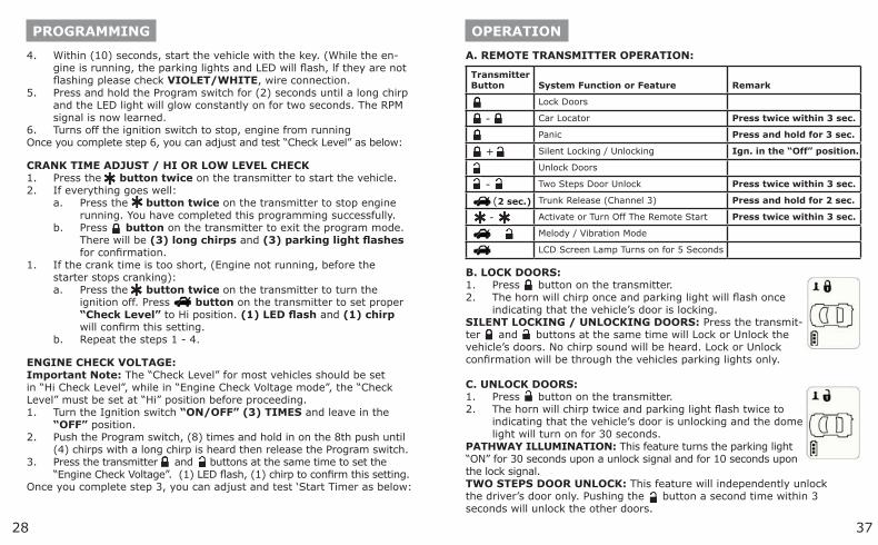
Within (10) seconds, start the vehicle with the key. (While the en-gine is running, the parking lights and LED will flash, lf they are not flashing please check VIOLET/WHITE, wire connection.Press and hold the Program switch for (2) seconds until a long chirp and the LED light will glow constantly on for two seconds. The RPM signal is now learned.Turns off the ignition switch to stop, engine from running
Once you complete step 6, you can adjust and test “Check Level” as below:
CRANK TIME ADJUST / HI OR LOW LEVEL CHECKPress the button twice on the transmitter to start the vehicle.If everything goes well:
Press the button twice on the transmitter to stop engine running. You have completed this programming successfully.Press button on the transmitter to exit the program mode. There will be (3) long chirps and (3) parking light flashes for confirmation.
If the crank time is too short, (Engine not running, before the starter stops cranking):
Press the button twice on the transmitter to turn the ignition off. Press button on the transmitter to set proper “Check Level” to Hi position. (1) LED flash and (1) chirp will confirm this setting.Repeat the steps 1 - 4.
ENGINE CHECK VOLTAGE:Important Note: The “Check Level” for most vehicles should be set in “Hi Check Level”, while in “Engine Check Voltage mode”, the “Check Level” must be set at “Hi” position before proceeding.
Turn the Ignition switch “ON/OFF” (3) TIMES and leave in the “OFF” position.Push the Program switch, (8) times and hold in on the 8th push until (4) chirps with a long chirp is heard then release the Program switch.Press the transmitter and buttons at the same time to set the “Engine Check Voltage”. (1) LED flash, (1) chirp to confirm this setting.
Once you complete step 3, you can adjust and test ‘Start Timer as below:
4.
5.
6.
1.2.
a.
b.
1.
a.
b.
1.
2.
3.
OPERATION
A. REMOTE TRANSMITTER OPERATION:
Transmitter Button System Function or Feature Remark
Lock Doors
- Car Locator Press twice within 3 sec.
Panic Press and hold for 3 sec.
+ Silent Locking / Unlocking Ign. in the “Off” position.
Unlock Doors
- Two Steps Door Unlock Press twice within 3 sec.
(2 sec.) Trunk Release (Channel 3) Press and hold for 2 sec.
- Activate or Turn Off The Remote Start Press twice within 3 sec.
Melody / Vibration Mode
LCD Screen Lamp Turns on for 5 Seconds
B. LOCK DOORS:Press button on the transmitter.The horn will chirp once and parking light will flash once indicating that the vehicle’s door is locking.
SILENT LOCKING / UNLOCKING DOORS: Press the transmit-ter and buttons at the same time will Lock or Unlock the vehicle’s doors. No chirp sound will be heard. Lock or Unlock confirmation will be through the vehicles parking lights only.
C. UNLOCK DOORS:Press button on the transmitter.The horn will chirp twice and parking light flash twice to indicating that the vehicle’s door is unlocking and the dome light will turn on for 30 seconds.
PATHWAY ILLUMINATION: This feature turns the parking light “ON” for 30 seconds upon a unlock signal and for 10 seconds upon the lock signal.TWO STEPS DOOR UNLOCK: This feature will independently unlock the driver’s door only. Pushing the button a second time within 3 seconds will unlock the other doors.
1.2.
1.2.
2936
PROGRAMMING
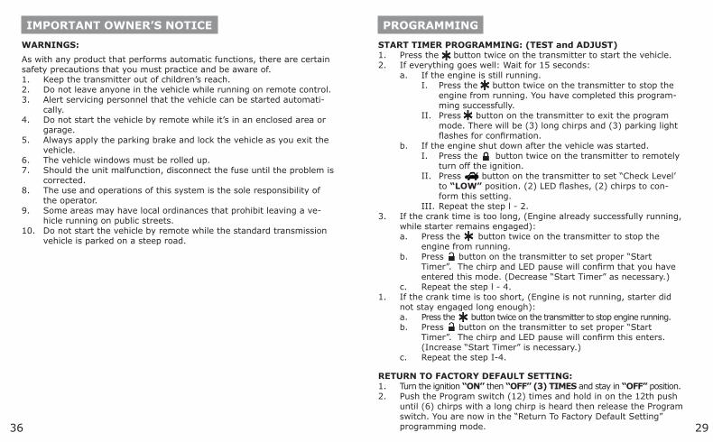
START TIMER PROGRAMMING: (TEST and ADJUST)Press the button twice on the transmitter to start the vehicle.If everything goes well: Wait for 15 seconds:
If the engine is still running.Press the button twice on the transmitter to stop the engine from running. You have completed this program-ming successfully.Press button on the transmitter to exit the program mode. There will be (3) long chirps and (3) parking light flashes for confirmation.
If the engine shut down after the vehicle was started.Press the button twice on the transmitter to remotely turn off the ignition.Press button on the transmitter to set “Check Level’ to “LOW” position. (2) LED flashes, (2) chirps to con-form this setting.Repeat the step l - 2.
If the crank time is too long, (Engine already successfully running, while starter remains engaged):
Press the button twice on the transmitter to stop the engine from running.Press button on the transmitter to set proper “Start Timer”. The chirp and LED pause will confirm that you have entered this mode. (Decrease “Start Timer” as necessary.)Repeat the step l - 4.
If the crank time is too short, (Engine is not running, starter did not stay engaged long enough):
Press the button twice on the transmitter to stop engine running.Press button on the transmitter to set proper “Start Timer”. The chirp and LED pause will confirm this enters. (Increase “Start Timer” is necessary.)Repeat the step I-4.
RETURN TO FACTORY DEFAULT SETTING:Turn the ignition “ON” then “OFF” (3) TIMES and stay in “OFF” position.Push the Program switch (12) times and hold in on the 12th push until (6) chirps with a long chirp is heard then release the Program switch. You are now in the “Return To Factory Default Setting” programming mode.
1.2.
a.I.
II.
b.I.
II.
III.3.
a.
b.
c.1.
a.b.
c.
1.2.
IMPORTANT OWNER’S NOTICE
WARNINGS:
As with any product that performs automatic functions, there are certain safety precautions that you must practice and be aware of.
Keep the transmitter out of children’s reach.Do not leave anyone in the vehicle while running on remote control.Alert servicing personnel that the vehicle can be started automati-cally.Do not start the vehicle by remote while it’s in an enclosed area or garage.Always apply the parking brake and lock the vehicle as you exit the vehicle.The vehicle windows must be rolled up.Should the unit malfunction, disconnect the fuse until the problem is corrected.The use and operations of this system is the sole responsibility of the operator.Some areas may have local ordinances that prohibit leaving a ve-hicle running on public streets.Do not start the vehicle by remote while the standard transmission vehicle is parked on a steep road.
1.2.3.
4.
5.
6.7.
8.
9.
10.
3530
PROGRAMMING
Press and hold the and buttons at the same time on the trans-mitter for 5 seconds, there will be a confirmation of (6) chirps with (3) long chirps and the LED turns On for (2) seconds to confirm the system, Feature Programming all returns to factory default setting.
SHUTDOWN DIAGNOSTICS:The unit has the ability to report the cause of the last shutdown of the remote start system.
Turn the Ignition switch to “ON” position.Press the button on the transmitter.The LED will now report the last system shutdown by flashing for (1) minute in the following grouped patterns:
LED Flashes Shutdown Mode
1 (-) Safety Shutdown Input (Hood)
1. Close the Hood 2. Check GREY wire connection
2 (+) Safety Shutdown input (Brake) or Neutral Safety Switch input fail
1. Check BROWN/RED wire connection 3. Move the Enable Toggle Switch to “ON” position. (If installed) 4. Move the gear selector to “PARK” / “NEUTRAL” position. 5. Check THIN BLACK wire connection.
3 No RPM (Engine Checking TACH) or Hi Voltage. (Engine Checking voltage.)
Check VIOLET/WHITE wire connection Program the “CHECK LEVEL” from “Hi Check Level” to “Low Check Level”
5 Over-rev
6 System timed out
7 Transmitter
8 Tach Signal has not been learned
Re-learning the RPM (Feature IV - 2)
3.
1.2.3.
TESTING YOUR INSTALLATION
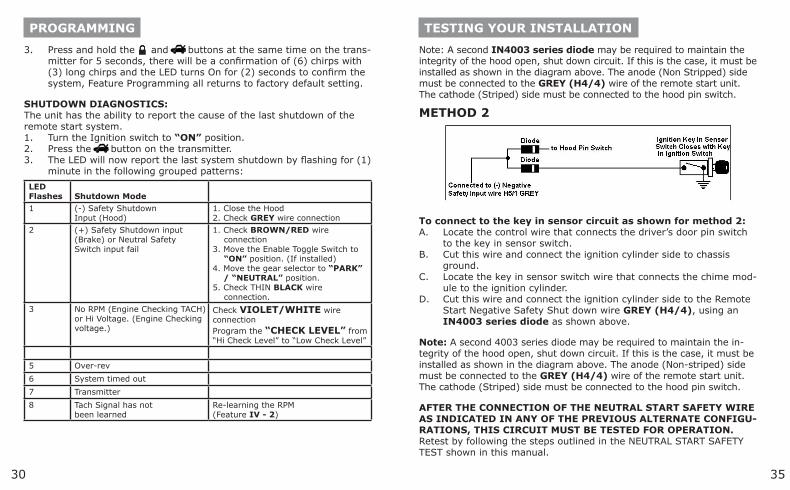
Note: A second IN4003 series diode may be required to maintain the integrity of the hood open, shut down circuit. If this is the case, it must be installed as shown in the diagram above. The anode (Non Stripped) side must be connected to the GREY (H4/4) wire of the remote start unit. The cathode (Striped) side must be connected to the hood pin switch.
METHOD 2
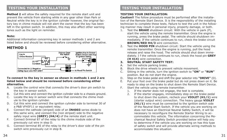
To connect to the key in sensor circuit as shown for method 2:Locate the control wire that connects the driver’s door pin switch to the key in sensor switch.Cut this wire and connect the ignition cylinder side to chassis ground.Locate the key in sensor switch wire that connects the chime mod-ule to the ignition cylinder.Cut this wire and connect the ignition cylinder side to the Remote Start Negative Safety Shut down wire GREY (H4/4), using an IN4003 series diode as shown above.
Note: A second 4003 series diode may be required to maintain the in-tegrity of the hood open, shut down circuit. If this is the case, it must be installed as shown in the diagram above. The anode (Non-striped) side must be connected to the GREY (H4/4) wire of the remote start unit. The cathode (Striped) side must be connected to the hood pin switch.
AFTER THE CONNECTION OF THE NEUTRAL START SAFETY WIRE AS INDICATED IN ANY OF THE PREVIOUS ALTERNATE CONFIGU-RATIONS, THIS CIRCUIT MUST BE TESTED FOR OPERATION.Retest by following the steps outlined in the NEUTRAL START SAFETY TEST shown in this manual.
A.
B.
C.
D.
3134
TESTING YOUR INSTALLATION
TESTING YOUR INSTALLATION:Caution!! The follow procedure must be performed after the installa-tion of the Remote Start Device. It is the responsibility of the installing technician to complete these tests. Failure to test the unit in the follow-ing manner may result in personal injury, property damage, or both.
Test the BRAKE shutdown circuit: With the vehicle in park (P), start the vehicle using the remote transmitter. Once the engine is running, press the brake pedal. The vehicle should shutdown im-mediately. If the vehicle continues to run, check the brake circuit BROWN/RED H4/3 wire connection.Test the HOOD PIN shutdown circuit: Start the vehicle using the remote transmitter. Once the engine is running, pull the hood release and raise the hood. The vehicle should shut down imme-diately. I f the vehicle continues to run, check the hood pin GREY (H 414) wire connection.NEUTRAL START SAFETY TEST:Set the vehicle parking brake.Block the drive wheels to prevent vehicle movement.Sitting in the vehicle, turn the ignition switch to “ON” or “RUN” position. But do not start the engine.Step on the brake pedal and shift the gear selector into “DRIVE” (D).Put your foot over the brake pedal but do not press down on it. Be ready to step on the brake to shut down the Remote Start Device.Start the vehicle using remote transmitter.
If the starter does not engage, the test is complete.If the starter engages, immediately step on the brake pedal to shut down the system, recheck your VIOLET (H1/1) wire (starter output wire) connection. The heavy gauge VIOLET (H1/1) wire must be connected to the ignition switch side of the Neutral Start Switch. If the vehicle you are working on does not have an Electrical Neutral Safety Switch, it will be necessary to reconfigure the Remote Starter Wiring to ac-commodate this vehicle. The information concerning the Me-chanical Neutral Safety Switch provided below will help you to determine if the vehicle you are working on has this type of safety switch and will provide alternate wiring methods to accommodate this situation.
1.
2.
3.A.B.C.
D.E.
F.1.2.
TESTING YOUR INSTALLATION
Method 2 will allow the safety required for the remote start unit and prevent the vehicle from starting while in any gear other than Park or Neutral while the key is in the ignition cylinder however, the original fac-tory key in chime module will not alert the owner that the key has been left in the ignition switch. In addition, this may also affect other warning tones such as the light on reminder.
Note:Additional information concerning key in sensor methods 1 and 2 are listed below and should be reviewed before considering either alternative.
METHOD 1
To connect to the key in sensor as shown in methods 1 and 2 are listed below and should be reviewed before considering either alternative.
Locate the control wire that connects the driver’s door pin switch to the key in sensor switch.Cut this wire and connect the ignition cylinder side to a chassis ground.Locate the key in sensor switch wire that connects the chime mod-ule to the ignition cylinder.Cut this wire and connect the ignition cylinder side to terminal 30 of a P&B VF45F11 or equivalent relay.Connect the cathode (striped) side of an IN4003 series diode to this same wire, and connect the (non striped) side to the negative safely input wire (GREY) (H4/4) of the remote start unit.Connect 0rminal 87 of the relay to the chime module side of the previously cut wire in step D.Connect terminal 85 of the relay to the driver’s door side of the pin switch wire previously cut in step B.
A.
B.C.
D.
E.
F.
G.
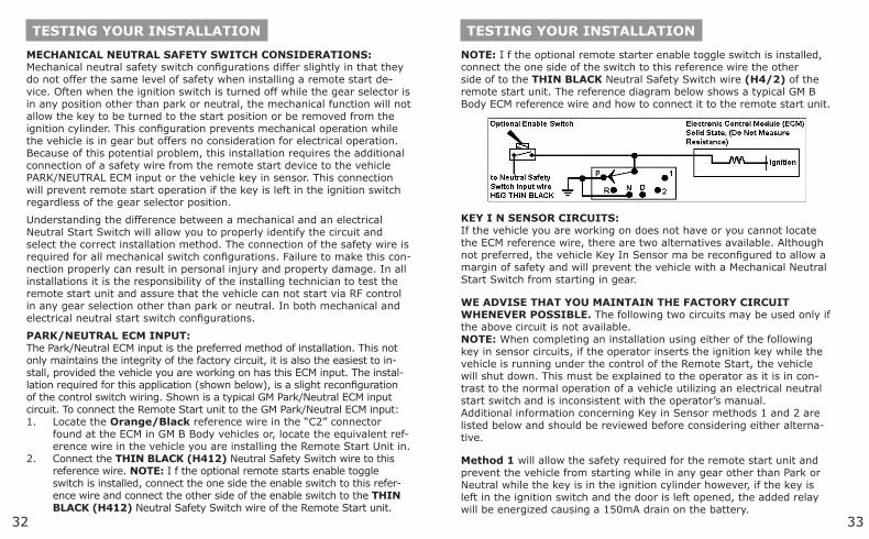
3332
TESTING YOUR INSTALLATION
MECHANICAL NEUTRAL SAFETY SWITCH CONSIDERATIONS:Mechanical neutral safety switch configurations differ slightly in that they do not offer the same level of safety when installing a remote start de-vice. Often when the ignition switch is turned off while the gear selector is in any position other than park or neutral, the mechanical function will not allow the key to be turned to the start position or be removed from the ignition cylinder. This configuration prevents mechanical operation while the vehicle is in gear but offers no consideration for electrical operation. Because of this potential problem, this installation requires the additional connection of a safety wire from the remote start device to the vehicle PARK/NEUTRAL ECM input or the vehicle key in sensor. This connection will prevent remote start operation if the key is left in the ignition switch regardless of the gear selector position.
Understanding the difference between a mechanical and an electrical Neutral Start Switch will allow you to properly identify the circuit and select the correct installation method. The connection of the safety wire is required for all mechanical switch configurations. Failure to make this con-nection properly can result in personal injury and property damage. In all installations it is the responsibility of the installing technician to test the remote start unit and assure that the vehicle can not start via RF control in any gear selection other than park or neutral. In both mechanical and electrical neutral start switch configurations.
PARK/NEUTRAL ECM INPUT:The Park/Neutral ECM input is the preferred method of installation. This not only maintains the integrity of the factory circuit, it is also the easiest to in-stall, provided the vehicle you are working on has this ECM input. The instal-lation required for this application (shown below), is a slight reconfiguration of the control switch wiring. Shown is a typical GM Park/Neutral ECM input circuit. To connect the Remote Start unit to the GM Park/Neutral ECM input:
Locate the Orange/Black reference wire in the “C2” connector found at the ECM in GM B Body vehicles or, locate the equivalent ref-erence wire in the vehicle you are installing the Remote Start Unit in.Connect the THIN BLACK (H412) Neutral Safety Switch wire to this reference wire. NOTE: I f the optional remote starts enable toggle switch is installed, connect the one side the enable switch to this refer-ence wire and connect the other side of the enable switch to the THIN BLACK (H412) Neutral Safety Switch wire of the Remote Start unit.
1.
2.
TESTING YOUR INSTALLATION
NOTE: I f the optional remote starter enable toggle switch is installed, connect the one side of the switch to this reference wire the other side of to the THIN BLACK Neutral Safety Switch wire (H4/2) of the remote start unit. The reference diagram below shows a typical GM B Body ECM reference wire and how to connect it to the remote start unit.
KEY I N SENSOR CIRCUITS:If the vehicle you are working on does not have or you cannot locate the ECM reference wire, there are two alternatives available. Although not preferred, the vehicle Key In Sensor ma be reconfigured to allow a margin of safety and will prevent the vehicle with a Mechanical Neutral Start Switch from starting in gear.
WE ADVISE THAT YOU MAINTAIN THE FACTORY CIRCUIT WHENEVER POSSIBLE. The following two circuits may be used only if the above circuit is not available. NOTE: When completing an installation using either of the following key in sensor circuits, if the operator inserts the ignition key while the vehicle is running under the control of the Remote Start, the vehicle will shut down. This must be explained to the operator as it is in con-trast to the normal operation of a vehicle utilizing an electrical neutral start switch and is inconsistent with the operator’s manual. Additional information concerning Key in Sensor methods 1 and 2 are listed below and should be reviewed before considering either alterna-tive.
Method 1 will allow the safety required for the remote start unit and prevent the vehicle from starting while in any gear other than Park or Neutral while the key is in the ignition cylinder however, if the key is left in the ignition switch and the door is left opened, the added relay will be energized causing a 150mA drain on the battery.