Installation, Start---up, Operating and Service and ... · Electrostatic discharge can affect...
58
58TP0A/58TP1A Variable---Speed, ECM Induced---Combustion 2---Stage Deluxe 4---Way Multipoise Gas Furnace Series A Installation, Start---up, Operating and Service and Maintenance Instructions SAFETY CONSIDERATIONS 2 ........................ INTRODUCTION 4 .................................. CODES AND STANDARDS 4 .......................... Safety 4 ........................................... General Installation 4 ................................ Combustion and Ventilation Air 4 ...................... Duct Systems 4 ..................................... Acoustical Lining and Fibrous Glass Duct 4 ............... Gas Piping and Gas Pipe Pressure Testing 4 ............... Electrical Connections 4 .............................. Venting 4 ......................................... ELECTROSTATIC DISCHARGE (ESD) PRECAUTIONS PROCEDURE 4 ..................................... LOCATION 6 ....................................... AIR FOR COMBUSTION AND VENTILATION 8 ......... Outdoor Combustion Air Method 9 .................... The Standard Method: 9 ............................ Combination of Indoor and Outdoor Air 10 ............. INSTALLATION 10 .................................. Upflow Installation 10 .............................. Downflow/Horizontal Installation 11 .................. Leveling Legs (If Desired) 11 ........................ Suspended Furnace Support 11 ....................... Platform Furnace Support 11 ......................... Roll--Out Protection 12 ............................. Bottom Return Air Inlet 12 .......................... Side Return Air Inlet 12 ............................. Filter Arrangement 13 .............................. AIR DUCTS 13 ...................................... Ductwork Acoustical Treatment 13 .................... Supply Air Connections 14 .......................... Upflow and Horizontal Furnaces 14 ................... Downflow Furnaces 14 ............................. Return Air Connections 22 .......................... Downflow Furnaces 22 ............................. Upflow and Horizontal Furnaces 22 ................... GAS PIPING 22 ..................................... ELECTRICAL CONNECTION 23 ....................... ACCESSORIES 25 ................................... VENTING 27 ....................................... START--UP, ADJUSTMENT, AND SAFETY CHECK 37 ..... General 37 ........................................ Start--Up Procedures 38 .............................. Adjustments 39 ..................................... Wiring Diagram 43 .................................. Check Safety Controls 47 ............................. Checklist 47 ....................................... SERVICE AND MAINTENANCE PROCEDURES 47 ....... General 48 ........................................ Care and Maintenance 49 ............................. Sequence of Operation 52 ............................. Troubleshooting 59 .................................. PARTS REPLACEMENT INFORMATION GUIDE 58 ....... D E S I G N C E R T I F I E D Use of the AHRI Certified TM Mark indicates a manufacturer’s participation in the program. For verification of certification for individual products, go to www.ahridirectory.org. ISO 9001 QMI-SAI Global NOTE: Read the entire instruction manual before starting the installation. Portions of the text and tables are reprinted from NFPA 54/ANSI Z223.1E, with permission of National Fire Protection Association, Quincy, MA 02269 and American Gas Association, Washington DC 20001. This reprinted material is not the complete and official position of the NFPA or ANSI on the referenced subject, which is represented only by the standard in its entirety.
Transcript of Installation, Start---up, Operating and Service and ... · Electrostatic discharge can affect...

58TP0A/58TP1AVariable---Speed, ECMInduced---Combustion 2---Stage Deluxe4---Way Multipoise Gas FurnaceSeries A
Installation, Start---up, Operating andService and Maintenance Instructions
SAFETY CONSIDERATIONS 2. . . . . . . . . . . . . . . . . . . . . . . .
INTRODUCTION 4. . . . . . . . . . . . . . . . . . . . . . . . . . . . . . . . . .
CODES AND STANDARDS 4. . . . . . . . . . . . . . . . . . . . . . . . . .
Safety 4. . . . . . . . . . . . . . . . . . . . . . . . . . . . . . . . . . . . . . . . . . .
General Installation 4. . . . . . . . . . . . . . . . . . . . . . . . . . . . . . . .
Combustion and Ventilation Air 4. . . . . . . . . . . . . . . . . . . . . .
Duct Systems 4. . . . . . . . . . . . . . . . . . . . . . . . . . . . . . . . . . . . .
Acoustical Lining and Fibrous Glass Duct 4. . . . . . . . . . . . . . .
Gas Piping and Gas Pipe Pressure Testing 4. . . . . . . . . . . . . . .
Electrical Connections 4. . . . . . . . . . . . . . . . . . . . . . . . . . . . . .
Venting 4. . . . . . . . . . . . . . . . . . . . . . . . . . . . . . . . . . . . . . . . .
ELECTROSTATIC DISCHARGE (ESD) PRECAUTIONSPROCEDURE 4. . . . . . . . . . . . . . . . . . . . . . . . . . . . . . . . . . . . .
LOCATION 6. . . . . . . . . . . . . . . . . . . . . . . . . . . . . . . . . . . . . . .
AIR FOR COMBUSTION AND VENTILATION 8. . . . . . . . .
Outdoor Combustion Air Method 9. . . . . . . . . . . . . . . . . . . .
The Standard Method: 9. . . . . . . . . . . . . . . . . . . . . . . . . . . .
Combination of Indoor and Outdoor Air 10. . . . . . . . . . . . .
INSTALLATION 10. . . . . . . . . . . . . . . . . . . . . . . . . . . . . . . . . .
Upflow Installation 10. . . . . . . . . . . . . . . . . . . . . . . . . . . . . .
Downflow/Horizontal Installation 11. . . . . . . . . . . . . . . . . .
Leveling Legs (If Desired) 11. . . . . . . . . . . . . . . . . . . . . . . .
Suspended Furnace Support 11. . . . . . . . . . . . . . . . . . . . . . .
Platform Furnace Support 11. . . . . . . . . . . . . . . . . . . . . . . . .
Roll--Out Protection 12. . . . . . . . . . . . . . . . . . . . . . . . . . . . .
Bottom Return Air Inlet 12. . . . . . . . . . . . . . . . . . . . . . . . . .
Side Return Air Inlet 12. . . . . . . . . . . . . . . . . . . . . . . . . . . . .
Filter Arrangement 13. . . . . . . . . . . . . . . . . . . . . . . . . . . . . .
AIR DUCTS 13. . . . . . . . . . . . . . . . . . . . . . . . . . . . . . . . . . . . . .
Ductwork Acoustical Treatment 13. . . . . . . . . . . . . . . . . . . .
Supply Air Connections 14. . . . . . . . . . . . . . . . . . . . . . . . . .
Upflow and Horizontal Furnaces 14. . . . . . . . . . . . . . . . . . .
Downflow Furnaces 14. . . . . . . . . . . . . . . . . . . . . . . . . . . . .
Return Air Connections 22. . . . . . . . . . . . . . . . . . . . . . . . . .
Downflow Furnaces 22. . . . . . . . . . . . . . . . . . . . . . . . . . . . .
Upflow and Horizontal Furnaces 22. . . . . . . . . . . . . . . . . . .
GAS PIPING 22. . . . . . . . . . . . . . . . . . . . . . . . . . . . . . . . . . . . .
ELECTRICAL CONNECTION 23. . . . . . . . . . . . . . . . . . . . . . .
ACCESSORIES 25. . . . . . . . . . . . . . . . . . . . . . . . . . . . . . . . . . .
VENTING 27. . . . . . . . . . . . . . . . . . . . . . . . . . . . . . . . . . . . . . .
START--UP, ADJUSTMENT, AND SAFETY CHECK 37. . . . .
General 37. . . . . . . . . . . . . . . . . . . . . . . . . . . . . . . . . . . . . . . .
Start--Up Procedures 38. . . . . . . . . . . . . . . . . . . . . . . . . . . . . .
Adjustments 39. . . . . . . . . . . . . . . . . . . . . . . . . . . . . . . . . . . . .
Wiring Diagram 43. . . . . . . . . . . . . . . . . . . . . . . . . . . . . . . . . .
Check Safety Controls 47. . . . . . . . . . . . . . . . . . . . . . . . . . . . .
Checklist 47. . . . . . . . . . . . . . . . . . . . . . . . . . . . . . . . . . . . . . .
SERVICE AND MAINTENANCE PROCEDURES 47. . . . . . .
General 48. . . . . . . . . . . . . . . . . . . . . . . . . . . . . . . . . . . . . . . .
Care and Maintenance 49. . . . . . . . . . . . . . . . . . . . . . . . . . . . .
Sequence of Operation 52. . . . . . . . . . . . . . . . . . . . . . . . . . . . .
Troubleshooting 59. . . . . . . . . . . . . . . . . . . . . . . . . . . . . . . . . .
PARTS REPLACEMENT INFORMATION GUIDE 58. . . . . . .
DES I GN
C E R T I F I E
D
Use of the AHRI Certified TM Mark indicates amanufacturer’s participation in the program. Forverification of certification for individual products,go to www.ahridirectory.org.
ISO 9001QMI-SAI Global
NOTE: Read the entire instruction manual before starting theinstallation.
Portions of the text and tables are reprinted from NFPA 54/ANSIZ223.1E, with permission of National Fire ProtectionAssociation, Quincy, MA 02269 and American Gas Association,Washington DC 20001. This reprinted material is not thecomplete and official position of the NFPA or ANSI on thereferenced subject, which is represented only by the standard inits entirety.

2
SAFETY CONSIDERATIONS
FIRE, EXPLOSION, ELECTRICAL SHOCK, ANDCARBONMONOXIDE POISONING HAZARD
Failure to follow this warning could result in dangerousoperation, personal injury, death, or property damage.
Improper installation, adjustment, alteration, service,maintenance, or use can cause carbon monoxide poisoning,explosion, fire, electrical shock, or other conditions whichmay cause personal injury or property damage. Consult aqualified service agency, local gas supplier, or yourdistributor or branch for information or assistance. Thequalified service agency must use only factory--authorizedand listed kits or accessories when modifying this product.
! WARNING
FURNACE RELIABILITY HAZARD
Failure to follow this caution may result in unit componentdamage.
Application of this furnace should be indoors with specialattention given to vent sizing and material, gas input rate,air temperature rise, unit leveling, and unit sizing.
CAUTION!
Installing and servicing heating equipment can be hazardous dueto gas and electrical components. Only trained and qualifiedpersonnel should install, repair, or service heating equipment.Untrained personnel can perform basic maintenance functionssuch as cleaning and replacing air filters. All other operationsmust be performed by trained service personnel. When workingon heating equipment, observe precautions in literature, on tags,and on labels attached to or shipped with furnace and other safetyprecautions that may apply.
These instructions cover minimum requirements and conform toexisting national standards and safety codes. In some instances,these instructions exceed certain local codes and ordinances,especially those that may not have kept up with changingresidential construction practices. We require these instructions asa minimum for a safe installation.
CUT HAZARD
Failure to follow this caution may result in personal injury.
Sheet metal parts may have sharp edges or burrs. Use careand wear appropriate protective clothing, safety glasses andgloves when handling parts, and servicing furnaces.
CAUTION!
Wear safety glasses, protective clothing and work gloves. Havefire extinguisher available during start--up and adjustmentprocedures and service calls.
This is the safety--alert symbol . When you see this symbol onthe furnace and in instructions or manuals, be alert to the potentialfor personal injury.
Understand the signal words DANGER, WARNING, andCAUTION. These words are used with the safety--alert symbol.DANGER identifies the most serious hazards which will result insevere personal injury or death. WARNING signifies a hazardwhich could result in personal injury or death. CAUTION is used
to identify hazards which may result in minor personal injury orproduct and property damage. NOTE is used to highlightsuggestions which will result in enhanced installation, reliability,or operation.
1. Use only with type of gas approved for this furnace. Referto the furnace rating plate.
2. Install this furnace only in a location and position as spe-cified in the “Location” section of these instructions.
3. Provide adequate combustion and ventilation air to thefurnace space as specified in “Air for Combustion andVentilation” section.
4. Combustion products must be discharged outdoors. Con-nect this furnace to an approved vent system only, as spe-cified in the “Venting” section of these instructions.
5. Never test for gas leaks with an open flame. Use a com-mercially available soap solution made specifically for thedetection of leaks to check all connections, as specified inthe “Gas Piping” section.
6. Always install furnace to operate within the furnace’s in-tended temperature--rise range with a duct system whichhas an external static pressure within the allowable range,as specified in the “Start--Up, Adjustments, and SafetyCheck” section. See furnace rating plate.
7. When a furnace is installed so that supply ducts carry aircirculated by the furnace to areas outside the space con-taining the furnace, the return air shall also be handled byduct(s) sealed to the furnace casing and terminating out-side the space containing the furnace. See “Air Ducts” sec-tion.
8. A gas--fired furnace for installation in a residential garagemust be installed as specified in the warning box in the“Location” section.
9. The furnace may be used for construction heat providedthat the furnace installation and operation complies withthe first CAUTION in the LOCATION section of these in-structions.
10. These Multipoise Gas--Fired Furnaces are CSA (formerlyA.G.A. and C.G.A.) design--certified for use with naturaland propane gases (see furnace rating plate) and for install-ation in alcoves, attics, basements, closets, utility rooms,crawlspaces, and garages. The furnace is factory--shippedfor use with natural gas. A CSA (A.G.A. and C.G.A.) lis-ted accessory gas conversion kit is required to convert fur-nace for use with propane gas.
11. See Fig. 1 for required clearances to combustible construc-tion.
12. Maintain a 1--in. (25 mm) clearance from combustible ma-terials to supply air ductwork for a distance of 36 in. (914mm) horizontally from the furnace. See NFPA 90B or loc-al code for further requirements.
13. These furnaces SHALL NOT be installed directly on car-peting, tile, or any other combustible material other thanwood flooring. In downflow installations, factory access-ory floor base MUST be used when installed on combust-ible materials and wood flooring. Special base is not re-quired when this furnace is installed on manufacturer’sCoil Assembly Part No. CNRV, CNPV, CAP, or CAR orwhen Coil Box Part No. KCAKC is used. See Fig. 1 forclearance to combustible construction information.

3
A10269
Fig. 1 -- Clearances to Combustibles
4
INTRODUCTIONThis 4--way multipoise Category I fan--assisted furnace is CSA(formerly A.G.A. and C.G.A.) design--certified. A Category Ifan--assisted furnace is an appliance equipped with an integralmechanical means to either draw or force products of combustionthrough the combustion chamber and/or heat exchanger. Thefurnace is factory--shipped for use with natural gas. This furnaceis not approved for installation in mobile homes, recreationalvehicles, or outdoors.
60
80 / 27 C
/ 16 C
A06745
Fig. 2 -- Return Air Temperature
This furnace is designed for minimum continuous return--airtemperature of 60_F (15_C) db or intermittent operation down to55_F (13_C)db such as when used with a night setbackthermostat. Return--air temperature must not exceed 80_F (27_C)db. Failure to follow these return--air temperature limits mayaffect reliability of heat exchangers, motors, and controls. (SeeFig. 2.)
For accessory installation details, refer to the applicableinstruction literature.
NOTE: Remove all shipping brackets and materials beforeoperating the furnace.
CODES AND STANDARDSFollow all national and local codes and standards in additionto these instructions. The installation must comply withregulations of the serving gas supplier, local building, heating,plumbing, and other codes. In absence of local codes, theinstallation must comply with the national codes listed below andall authorities having jurisdiction.
In the United States, follow all codes and standards for thefollowing:
Safety
NFPA 54/ANSI Z223.1 and the Installation Standards, Warm AirHeating and Air Conditioning Systems ANSI/NFPA 90B .
General Installation
Current edition of the NFGC and the NFPA 90B. For copies,contact the National Fire Protection Association Inc.,Batterymarch Park, Quincy, MA 02269; (www.NFPA.org) or foronly the NFGC, contact the American Gas Association, 400 N.Capitol Street, N.W., Washington, DC 20001 (www.AGA.org.) .
Combustion and Ventilation Air
Section 9.3 NFPA 54/ANSI Z223.1, Air for Combustion andVentilation .
Duct Systems
Air Conditioning Contractors Association (ACCA) Manual D,Sheet Metal and Air Conditioning Contractors National
Association (SMACNA), or American Society of Heating,Refrigeration, and Air Conditioning Engineers (ASHRAE) 2001Fundamentals Handbook Chapter 35 or 2005 HVAC Systemsand Equipment Handbook Chapters 9 and 16.
Acoustical Lining and Fibrous Glass Duct
Current edition of SMACNA and NFPA 90B as tested by ULStandard 181 for Class I Rigid Air Ducts
Gas Piping and Gas Pipe Pressure Testing
NFPA 54/ANSI Z223.1 ; chapters 5, 6, and 7 and NationalPlumbing Codes .
Electrical Connections
National Electrical Code (NEC) ANSI/NFPA70 .
Venting
NFPA 54/ANSI Z223.1; chapters 12 and 13.
ELECTROSTATIC DISCHARGE (ESD)PRECAUTIONS PROCEDURE
FURNACE RELIABILITY HAZARD
Failure to follow this caution may result in unit componentdamage.
Electrostatic discharge can affect electronic components.Take precautions during furnace installation and servicingto protect the furnace electronic control. Precautions willprevent electrostatic discharges from personnel and handtools which are held during the procedure. Theseprecautions will help to avoid exposing the control toelectrostatic discharge by putting the furnace, the control,and the person at the same electrostatic potential.
CAUTION!
1. Disconnect all power to the furnace. Multiple disconnectsmay be required. DO NOT TOUCH THE CONTROL ORANY WIRE CONNECTED TO THE CONTROL PRIORTO DISCHARGING YOUR BODY’SELECTROSTATIC CHARGE TO GROUND.
2. Firmly touch the clean, unpainted, metal surface of the fur-nace chassis which is close to the control. Tools held in aperson’s hand during grounding will be satisfactorily dis-charged.
3. After touching the chassis, you may proceed to service thecontrol or connecting wires as long as you do nothing torecharge your body with static electricity (for example;DO NOT move or shuffle your feet, do not touch un-grounded objects, etc.).
4. If you touch ungrounded objects (and recharge your bodywith static electricity), firmly touch a clean, unpaintedmetal surface of the furnace again before touching controlor wires.
5. Use this procedure for installed and uninstalled (ungroun-ded) furnaces.
6. Before removing a new control from its container, dis-charge your body’s electrostatic charge to ground to pro-tect the control from damage. If the control is to be in-stalled in a furnace, follow items 1 through 4 beforebringing the control or yourself in contact with the fur-nace. Put all used and new controls into containers beforetouching ungrounded objects.
7. An ESD service kit (available from commercial sources)may also be used to prevent ESD damage.

5
A190045
FURNACE SIZE
A B C D
VENTCONNECTION
SIZESHIP WT.LB (KG)
ACCESSORYFILTERMEDIACABINETSIZE
CABINETWIDTH
OUTLETWIDTH
TOP ANDBOTTOM FLUECOLLAR
BOTTOMINLET WIDTH
045V14---12 14-3/16 (360) 12-9/16 (319) 9-5/16 (237) 12---11/16 (322) 4 (102) 111 (50) 16 (406)070V14---12 14-3/16 (360) 12-9/16 (319) 9-5/16 (237) 12---11/16 (322) 4 (102) 118 (54) 16 (406)070V17---16 17---1/2 (445) 15-7/8 (403) 11-9/16 (294) 16 (406) 4 (102) 132 (60) 16 (406)090V17---16 17---1/2 (445) 15-7/8 (403) 11-9/16 (294) 16 (406) 4 (102) 131 (59) 16 (406)090V21---20 21 (533) 19-3/8 (492) 13-5/16 (338) 19---1/2 (495) 4 (102) 142 (64) 20 (506)110V21---22 21 (533) 19-3/8 (492) 13-5/16 (338) 19---1/2 (495) 4 (102) 154 (70) 20 (506)135V24---22 24-1/2 (622) 22-7/8 (581 15-1/16 (383) 23 (584) 4 (102)* 168 (76) 24 (610)
*135 size furnaces require a 5 or 6---in. (127 or 152 mm) vent. Use a vent adapter between furnace and vent stack. See Installation Instructions for completeinstallation requirements.
Fig. 3 -- Dimensional Drawing

6
LOCATIONGENERALThis multipoise furnace is shipped in packaged configuration.Some assembly and modifications are required when used in anyof the four applications shown in Fig. 4.
NOTE: For high--altitude installations, the high--altitudeconversion kit MUST be installed at or above 5500 ft. (1676 M)above sea level. Obtain high--altitude conversion kit from yourarea authorized distributor.
THE BLOWER IS LOCATEDTO THE RIGHT OF THE
BURNER SECTION, ANDAIR CONDITIONED AIR IS
DISCHARGED TO THE LEFT.
THE BLOWER ISLOCATED BELOW THE
BURNER SECTION, ANDCONDITIONED AIR IS
DISCHARGED UPWARD.
THE BLOWER ISLOCATED ABOVE THE
BURNER SECTION, ANDCONDITIONED AIR IS
DISCHARGED DOWNWARD
THE BLOWER ISLOCATED TO THE LEFT
OF THE BURNER SECTION,AND CONDITIONED AIR IS
DISCHARGED TO THE RIGHT.
A02097
Fig. 4 -- Multipoise Orientations
This furnace must:
S be installed so the electrical components are protectedfrom water.
S not be installed directly on any combustible materialother than wood flooring (refer to SAFETYCONSIDERATIONS).
S be located close to the chimney or vent and attached toan air distribution system. Refer to Air Ducts section.
S be provided ample space for servicing and cleaning.Always comply with minimum fire protection clear-ances shown on the furnace clearance to combustibleconstruction label.
CARBON MONOXIDE POISONING / COMPONENTDAMAGE HAZARD
Failure to follow this warning could result in personal injuryor death and unit component damage.
Corrosive or contaminated air may cause failure of partscontaining flue gas, which could leak into the living space.Air for combustion must not be contaminated by halogencompounds, which include fluoride, chloride, bromide, andiodide. These elements can corrode heat exchangers andshorten furnace life. Air contaminants are found in aerosolsprays, detergents, bleaches, cleaning solvents, salts, airfresheners, and other household products. Do not installfurnace in a corrosive or contaminated atmosphere. Makesure all combustion and circulating air requirements are met,in addition to all local codes and ordinances.
! WARNING
The following types of furnace installations may requireOUTDOOR AIR for combustion due to chemical exposures:
S Commercial buildings
S Buildings with indoor pools
S Laundry rooms
S Hobby or craft rooms, and
S Chemical storage areas
If air is exposed to the following substances, it should not be usedfor combustion air, and outdoor air may be required forcombustion:
S Permanent wave solutions
S Chlorinated waxes and cleaners
S Chlorine based swimming pool chemicals
S Water softening chemicals
S De--icing salts or chemicals
S Carbon tetrachloride
S Halogen type refrigerants
S Cleaning solvents (such as perchloroethylene)
S Printing inks, paint removers, varnishes, etc.
S Hydrochloric acid
S Cements and glues
S Antistatic fabric softeners for clothes dryers
S Masonry acid washing materials
7
All fuel--burning equipment must be supplied with air for fuelcombustion. Sufficient air must be provided to avoid negativepressure in the equipment room or space. A positive seal must bemade between the furnace cabinet and the return--air duct toprevent pulling air from the burner area and from draft safeguardopening.
FIRE, INJURY OR DEATH HAZARD
Failure to follow this warning could result in personalinjury, death and/or property damage.
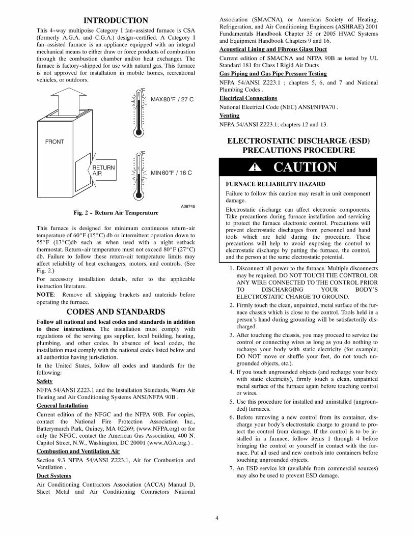
When the furnace is installed in a residential garage, theburners and ignition sources must be located at least 18 in.(457 mm) above the floor. The furnace must be located orprotected to avoid damage by vehicles. When the furnace isinstalled in a public garage, airplane hangar, or otherbuilding having a hazardous atmosphere, the furnace mustbe installed in accordance with the NFPA 54/ANSI Z223.1 .(See Fig. 5.)
! WARNING
18-IN. (457.2 mm) MINIMUM TO BURNERS
A93044
Fig. 5 -- Installation in a Garage
FIRE HAZARD
Failure to follow this warning could result in personalinjury, death and/or property damage.
Do not install the furnace on its back or hang furnace withcontrol compartment facing downward. Safety controloperation will be adversely affected. Never connectreturn--air ducts to the back of the furnace. (See Fig. 6.)
! WARNING
LOCATION RELATIVE TO COOLING EQUIPMENT
The cooling coil must be installed parallel with, or on thedownstream side of the unit to avoid condensation in the heatexchangers. When installed parallel with the furnace, dampers orother flow control must prevent chilled air from entering thefurnace. If the dampers are manually operated, they must beequipped with means to prevent operation of either unit unlessthe damper is in the full--heat or full--cool position.
PERSONAL INJURY AND/OR PROPERTYDAMAGE HAZARD
Improper use or installation of this furnace may result inpremature furnace component failure. This gas furnace maybe used for heating buildings under construction providedthat:
--The furnace is permanently installed with all electricalwiring, piping, venting and ducting installed according tothese installation instructions. A return air duct is provided,sealed to the furnace casing, and terminated outside thespace containing the furnace. This prevents a negativepressure condition as created by the circulating air blower,causing a flame rollout and/or drawing combustionproducts into the structure.
--The furnace is controlled by a thermostat. It may not be“hot wired” to provide heat continuously to the structurewithout thermostatic control.
--Clean outside air is provided for combustion. This is tominimize the corrosive effects of adhesives, sealers andother construction materials. It also prevents theentrainment of drywall dust into combustion air, which cancause fouling and plugging of furnace components.
--The temperature of the return air to the furnace ismaintained between 55_F (13_C) and 80_F (27_C), withno evening setback or shutdown. The use of the furnacewhile the structure is under construction is deemed to beintermittent operation per our installation instructions.
--The air temperature rise is within the rated rise range onthe furnace rating plate, and the gas input rate has been setto the nameplate value. --The filters used to clean thecirculating air during the construction process must beeither changed or thoroughly cleaned prior to occupancy.
--The furnace, ductwork and filters are cleaned as necessaryto remove drywall dust and construction debris from allHVAC system components after construction is completed.
--Verify proper furnace operating conditions includingignition, gas input rate, air temperature rise, and ventingaccording to these installation instructions.
CAUTION!
A02054
Fig. 6 -- Prohibit Installation on Back

8
Table 1 – Minimum Free Area Required for Each Combustion Air opening of Duct to Outdoors
FURNACEINPUT(BTUH)
TWO HORIZONTAL DUCTS SINGLE DUCT OR OPENING TWO OPENINGS OR VERTICAL DUCTS(1 SQ. IN./2,000 BTUH) (1,100 SQ. MM/KW) (1 SQ. IN./3,000 BTUH) (734 SQ. MM/KW) (1 SQ. IN./4,000 BTUH) (550 SQ. MM/KW)Free Area of Opening
and DuctSq. In. (Sq. mm)
Round DuctDia.In. (mm)
Free Area of Openingand Duct
Sq. In. (Sq. mm)
Round DuctDia.In. (mm)
Free Area of Openingand Duct
Sq. In. (Sq. mm)
Round DuctDia.In. (mm)
44,000 22 (14194) 6 (152) 14.7 (9484) 5 (127) 11 (7096) 4 (102)66,000 33 (21290) 7 (178) 22 (14193) 6 (152) 16.5 (10645) 5 (127)88,000 44 (28387) 8 (203) 29.3 (18903) 7 (178) 22 (14193) 6 (152)110,000 55 (35484) 9 (229) 36.7 (23677) 7 (178) 27.5 (17742) 6 (152)132,000 66 (42580) 10 (254) 44 (28387) 8 (203) 33 (21290) 7 (178)154,000 77 (49677) 10 (254) 51.3 (33096) 9 (229) 38.5 (24839) 8 (203)
Note: Not all models have these sizes.
EXAMPLES: Determining Free AreaFURNACE WATER HEATER TOTAL INPUT
110,000 + 30,000 = (140,000 divided by 4,000) = 35.0 Sq. In. for each two Vertical Ducts or Openings66,000 + 40,000 = (106,000 divided by 3,000) = 35.3 Sq. In. for a Single Duct or Opening88,000 + 30,000 = (118,000 divided by 2,000) = 59.0 Sq. In. for each of two Horizontal Ducts
Table 2 – Minimum Space Volumes for 100% Combustion, Ventilation, and Dilution from Indoors
OTHER THAN FAN-ASSISTED TOTAL(1,000’S BTUH GAS INPUT RATE)
FAN-ASSISTED TOTAL(1,000’S BTUH GAS INPUT RATE)
ACH30 40 50 44 66 88 110 132 154
Space Volume Ft3 (M3)
0.60 1,050(29.7)
1,400(39.6)
1,750(49.5)
1,100(31.1)
1,650(46.7)
2,200(62.2)
2,750(77.8)
3,300(93.4)
3,850(109.0)
0.50 1,260(35.6)
1,680(47.5)
2,100(59.4)
1,320(37.3)
1,980(56.0)
2,640(74.7)
3,300(93.4)
3,960(112.1)
4,620(130.8)
0.40 1,575(44.5)
2,100(59.4)
2,625(74.3)
1,650(46.7)
2,475(70.0)
3,300(93.4)
4,125(116.8)
4,950(140.1)
5,775(163.5)
0.30 2,100(59.4)
2,800(79.2)
3,500(99.1)
2,200(62.2)
3,300(93.4)
4,400(124.5)
5,500(155.7)
6,600(186.8)
7,700(218.0)
0.20 3,150(89.1)
4,200(118.9) 5,250 (148.6) 3,300
(93.4)4,950(140.1)
6,600(186.8)
8,250(233.6)
9,900(280.3)
11,550(327.0)
0.10 6,300(178.3)
8,400(237.8)
10,500(297.3)
6,600(186.8)
9,900(280.3)
13,200(373.7)
16,500(467.2)
19,800(560.6)
23,100(654.1)
0.00 NP NP NP NP NP NP NP NP NP
NP = Not PermittedNote: Not all models have these sizes.
AIR FOR COMBUSTION ANDVENTILATION
Provisions for adequate combustion, ventilation, and dilution airmust be provided in accordance with:
S U.S. Installations: Section 9.3 of the NFPA 54/ANSIZ223.1 , Air for Combustion and Ventilation and ap-plicable provisions of the local building codes.
FURNACE CORROSION HAZARD
Failure to follow this caution may result in furnace damage.
Air for combustion must not be contaminated by halogencompounds, which include fluoride, chloride, bromide, andiodide. These elements can corrode heat exchangers andshorten furnace life. Air contaminants are found in aerosolsprays, detergents, bleaches, cleaning solvents, salts, airfresheners, and other household products.
CAUTION!
CARBONMONOXIDE POISONING HAZARD
Failure to follow this warning could result in personalinjury or death.
The operation of exhaust fans, kitchen ventilation fans,clothes dryers, attic exhaust fans or fireplaces could create aNEGATIVE PRESSURE CONDITION at the furnace.Make--up air MUST be provided for the ventilation devices,in addition to that required by the furnace. Refer to theCarbon Monoxide Poisoning Hazard warning in the ventingsection of these instructions to determine if an adequateamount of make--up air is available.
! WARNING
The requirements for combustion and ventilation air depend uponwhether or not the furnace is located in a space having a volumeof at least 50 cubic feet per 1,000 Btuh input rating for all gasappliances installed in the space.
S Spaces having less than 50 cubic feet per 1,000 Btuhrequire the OUTDOOR COMBUSTION AIRMETHOD.
9
1 SQ IN . PER 4000
BTUH*
DUCTS TO
O UTDOORS
1 SQ IN. PER 4000 BTUH*
C IR
CU
LA TI
NG
A
IR D
UC
TS VENT
THR OUGH R OOF
D
B
A
C
E
1 SQ IN. PER 4000 BTUH*
DUCT TO
OUTDOORS
CIRCULA TING AIR DUCT S
1 SQ IN. PER 2000 BTUH*
1 SQ IN. PER 2000 BTUH*
DUCT S TO
OUTDOORS
12 ″ MAX
12 ″ MAX
12 ″ MAX
12 ″MAX
12 ″MAX
OU
TDO
OR
S
1 SQ IN . PER 4000
BTUH*
F
G
CLE
AR
AN
CE
IN F
RO
NT
O
F C
OM
B U
ST
ION
AIR
O
PE
NIN
GS
SH
ALL
BE
A
T L
EA
ST
3 IN
.
(305mm) (305mm)
(305mm) (305mm)
(305mm)
(76m
m)
*Minimum dimensions of 3--- in. (76 mm).NOTE: Use any of the following combinations of openings:
A & B C & D D & E F & GA03174
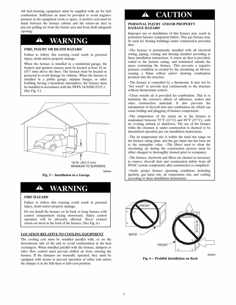
Fig. 7 -- Air for Combustion, Ventilation, and Dilution forOutdoors
S Spaces having at least 50 cubic feet per 1,000 Btuhmay use the INDOOR COMBUSTION AIR,STANDARD or KNOWN AIR INFILTRATIONMETHOD.
Outdoor Combustion Air Method
1. Provide the space with sufficient air for proper combus-tion, ventilation, and dilution of flue gases using perman-ent horizontal or vertical duct(s) or opening(s) directlycommunicating with the outdoors or spaces that freelycommunicate with the outdoors.
2. Fig. 7 illustrates how to provide TWO OUTDOOROPENINGS, one inlet and one outlet combustion andventilation air opening, to the outdoors.
a. One opening MUST commence within 12 in. (300mm) of the ceiling and the second opening MUSTcommence within 12 in. (300 mm) of the floor.
b. Size openings and ducts per Fig. 7 and Table 1.
c. TWO HORIZONTAL DUCTS require 1 sq. in. (645sq. mm) of free area per 2,000 Btuh (1,100 mm2/kW)of combined input for all gas appliances in the spaceper Fig. 7 and Table 1.
d. TWO OPENINGS OR VERTICAL DUCTS require 1sq. in. (645 sq. mm) of free area per 4,000 Btuh (550mm2/kW) for combined input of all gas appliances inthe space per Fig. 7 and Table 1.
3. ONE OUTDOOR OPENING requires:
a. 1 sq. in. (645 sq. mm) of free area per 3,000 Btuh(734 mm2/kW) for combined input of all gas appli-ances in the space per Table 1 and
b. Not less than the sum of the areas of all vent connect-ors in the space.
CIRCULATING AIR DUCTS
6" MIN (FRONT)Ü
CIRCULATING AIR DUCTS
VENT THROUGH ROOF
1 SQ IN. PER 1000 BTUH* IN DOOR OR WALL
12" MAX
1 SQ IN. PER 1000 BTUH* IN DOOR OR WALL
12" MA X
UNCONFINED SPACE
INTERIOR HEATED SPACE
CLE
AR
AN
CE
IN F
RO
NT
OF
CO
MB
US
TIO
N A
IR
O
PE
NIN
GS
SH
ALL
BE
AT
LEA
ST 3
IN.
(305mm)
(152mm)
(305mm)
* Minimum opening size is 100 sq in. (64516 sq. mm)with minimum dimensionsof 3 in. (76 mm)† Minimum of 3 in. (76 mm) when type-B1 vent is used.
A03175
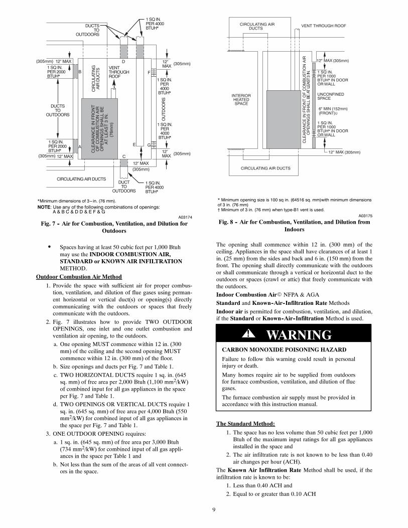
Fig. 8 -- Air for Combustion, Ventilation, and Dilution fromIndoors
The opening shall commence within 12 in. (300 mm) of theceiling. Appliances in the space shall have clearances of at least 1in. (25 mm) from the sides and back and 6 in. (150 mm) from thefront. The opening shall directly communicate with the outdoorsor shall communicate through a vertical or horizontal duct to theoutdoors or spaces (crawl or attic) that freely communicate withthe outdoors.
Indoor Combustion AirE NFPA & AGA
Standard and Known--Air--Infiltration RateMethodsIndoor air is permitted for combustion, ventilation, and dilution,if the Standard or Known--Air--Infiltration Method is used.
CARBONMONOXIDE POISONING HAZARD
Failure to follow this warning could result in personalinjury or death.
Many homes require air to be supplied from outdoorsfor furnace combustion, ventilation, and dilution of fluegases.
The furnace combustion air supply must be provided inaccordance with this instruction manual.
! WARNING
The Standard Method:
1. The space has no less volume than 50 cubic feet per 1,000Btuh of the maximum input ratings for all gas appliancesinstalled in the space and
2. The air infiltration rate is not known to be less than 0.40air changes per hour (ACH).
The Known Air Infiltration Rate Method shall be used, if theinfiltration rate is known to be:
1. Less than 0.40 ACH and
2. Equal to or greater than 0.10 ACH

10
Infiltration rates greater than 0.60 ACH shall not be used. Theminimum required volume of the space varies with the number ofACH and shall be determined per Table 2 or Equations 1 and 2.Determine the minimum required volume for each appliance inthe space and add the volumes together to get the total minimumrequired volume for the space.
Table 2 -- Minimum Space Volumes were determined by usingthe following equations from the National Fuel Gas Code ANSIZ223.1/NFPA 54, 9.3.2.2:
1. For other than fan--assisted appliances, such as a drafthood--equipped water heater:
VolumeOther
= 21ft3ACH
I other
1000 Btu/hr
A04002
2. For fan--assisted appliances such as this furnace:
VolumeFan
= 15ft3ACH
I fan
1000 Btu/hr
A04003
If: Iother = combined input of all other than fan--assistedappliances in Btuh/hr
Ifan = combined input of all fan--assisted appliances in Btuh/hr
ACH = air changes per hour (ACH shall not exceed 0.60.)
The following requirements apply to the Standard Method andto the Known Air Infiltration RateMethod.
1. Adjoining rooms can be considered part of a space if:
a. There are no closeable doors between rooms.
b. Combining spaces on same floor level. Each openingshall have free area of at least 1 in.2/1,000 Btuh (2,000mm2/kW) of the total input rating of all gas appliancesin the space, but not less than 100 in.2 (0.06 m2). Oneopening shall commence within 12 in. (300 mm) ofthe ceiling and the second opening shall commencewithin 12 in. (300 mm) of the floor. The minimumdimension of air openings shall be at least 3 in. (80mm). (See Fig. 8.)
c. Combining space on different floor levels. Thevolumes of spaces on different floor levels shall beconsidered as communicating spaces if connected byone or more permanent openings in doors or floorshaving free area of at least 2 in.2/1,000 Btuh (4,400mm2/kW) of total input rating of all gas appliances.
2. An attic or crawlspace may be considered a space thatfreely communicates with the outdoors provided there areadequate permanent ventilation openings directly to out-doors having free area of at least 1--in.2/4,000 Btuh of totalinput rating for all gas appliances in the space.
3. In spaces that use the Indoor Combustion Air Method,infiltration should be adequate to provide air for combus-tion, permanent ventilation and dilution of flue gases.However, in buildings with unusually tight construction,additional air MUST be provided using the methods de-scribed in the Outdoor Combustion AirMethod section.
4. Unusually tight construction is defined as Constructionwith:
a. Walls and ceilings exposed to the outdoors have a con-tinuous, sealed vapor barrier. Openings are gasketed orsealed and
b. Doors and openable windows are weatherstripped and
c. Other openings are caulked or sealed. These includejoints around window and door frames, between sole
plates and floors, between wall--ceiling joints, betweenwall panels, at penetrations for plumbing, electricaland gas lines, etc.
Combination of Indoor and Outdoor Air
1. Indoor openings shall comply with the Indoor Combus-tion AirMethod below and,
2. Outdoor openings shall be located as required in the Out-door Combustion AirMethod mentioned previously and,
3. Outdoor openings shall be sized as follows:
a. Calculate the Ratio of all Indoor Space volume dividedby required volume for Indoor Combustion AirMethod below.
b. Outdoor opening size reduction Factor is 1 minus theRatio in a. above.
c. Minimum size of Outdoor openings shall be the sizerequired in Outdoor Combustion AirMethod abovemultiplied by reduction Factor in b. above. The min-imum dimension of air openings shall be not less than3 in. (80 mm).
INSTALLATIONUPFLOW INSTALLATION
Bottom Return Air Inlet
These furnaces are shipped with bottom closure panel installed inbottom return--air opening. Remove and discard this panel whenbottom return air is used. To remove bottom closure panel,perform the following:
1. Tilt or raise furnace and remove 2 screws holding bottomfiller panel. (See Fig. 9.)
2. Rotate bottom filler panel downward to release holdingtabs.
3. Remove bottom closure panel.
4. Reinstall bottom filler panel and screws.
Side Return Air Inlet
These furnaces are shipped with bottom closure panel installed inbottom return--air opening. This panel MUST be in place whenonly side return air is used.
BottomClosure Panel
Bottom Filler Panel
A10273
Fig. 9 -- Removing Bottom Closure Panel
NOTE: Side return--air openings can be used in UPFLOW andmost HORIZONTAL configurations. Do not use side return--airopenings in DOWNFLOW configuration.
Leveling Legs (If Desired)
In upflow position with side return inlet(s), leveling legs may beused. (See Fig. 10.) Install field--supplied, 5/16 X 1--1/2 in. (8 X38 mm) (max) corrosion--resistant machine bolts, washers andnuts.

11
1 3 / 4
1 3 / 4
1 3/ 4 1 3/ 4
5/ 16
5 / 16
5/ 16
5/ 16
(44mm)
(8mm)
(44mm)
(8mm)
(8mm)
(8mm)
(44mm) (44mm)
A89014
Fig. 10 -- Leveling Legs
NOTE: Bottom closure must be used when leveling legs areused. It may be necessary to remove and reinstall bottom closurepanel to install leveling legs. To remove bottom closure panel, seeItem 1 in Bottom Return Air Inlet section in Step 1 above.
To install leveling legs:
1. Position furnace on its back. Locate and drill a hole ineach bottom corner of furnace. (See Fig. 10.)
2. For each leg, install nut on bolt and then install bolt withnut in hole. (Install flat washer if desired.)
3. Install another nut on other side of furnace base. (Installflat washer if desired.)
4. Adjust outside nut to provide desired height, and tighteninside nut to secure arrangement.
5. Reinstall bottom closure panel if removed.
DOWNFLOW INSTALLATION
NOTE: For downflow applications, this furnace is approved foruse on combustible flooring when any one of the following 3accessories are used:
S Special Base, KGASB
S Cased Coil Assembly Part No. CNPV, CNRV, CAP, orCAR
S Coil Box Part No. KCAKC
1. Determine application being installed from Table 3.
2. Construct hole in floor per Table 3 and Fig. 11.
3. Construct plenum to dimensions specified in Table 3 andFig. 11.
4. If downflow subbase, KGASB is used, install as shown inFig. 12. If Coil Assembly Part No. CPVP, CAPMP orCNPVP Coil Box Part No. KCAKC is used, install asshown in Fig. 13.
NOTE: It is recommended that the perforated supply--air ductflanges be completely folded over or removed from furnace wheninstalling the furnace on a factory--supplied cased coil or coil box.To remove the supply--air duct flange, use wide duct pliers orhand seamers to bend flange back and forth until it breaks off. Becareful of sharp edges. (See Fig. 14.)
Bottom Return Air Inlet
These furnaces are shipped with bottom closure panel installed inbottom return--air opening. Remove and discard this panel whenbottom return air is used. To remove bottom closure panel,perform the following:
1. Tilt or raise furnace and remove 2 screws holding bottomfiller panel. (See Fig. 9.)
2. Rotate bottom filler panel downward to release holdingtabs.
3. Remove bottom closure panel.
4. Reinstall bottom filler panel and screws.
HORIZONTAL INSTALLATION
FIRE, EXPLOSION, AND CARBON MONOXIDEPOISONING HAZARD
Failure to follow this warning could result in personalinjury, death, or property damage.
Do not install the furnace on its back or hang furnace withcontrol compartment facing downward. Safety controloperation will be adversely affected. Never connectreturn--air ducts to the back of the furnace.
! WARNING
The furnace can be installed horizontally in an attic or crawlspaceon either the left--hand (LH) or right--hand (RH) side. The furnacecan be hung from floor joists, rafters or trusses or installed on anon--combustible platform, blocks, bricks or pad.
Suspended Furnace Support
The furnace may be supported under each end with threaded rod,angle iron or metal plumber’s strap as shown. (See Fig. 15 and16.) Secure angle iron to bottom of furnace as shown.Heavy--gauge sheet metal straps (plumber’s straps) may be usedto suspend the furnace from each bottom corner. To preventscrews from pulling out, use 2 #8 x 3/4 in. screws into the sideand 2 #8 x in. screws in the bottom of the furnace casing for eachstrap. (See Fig. 15 and 16.)
If the screws are attached to ONLY the furnace sides and not thebottom, the straps must be vertical against the furnace sides andnot pull away from the furnace sides, so that the strap attachmentscrews are not in tension (are loaded in shear) for reliable support.
Platform Furnace Support
Construct working platform at location where all required furnaceclearances are met. (See Fig. 1 and 17.) For furnaces with 1--in.(25 mm) clearance requirement on side, set furnace onnon--combustible blocks, bricks or angle iron. For crawlspaceinstallations, if the furnace is not suspended from the floor joists,the ground underneath furnace must be level and the furnace seton blocks or bricks.

12
PLENUMOPENING
C
A
B D
FLOOROPENING
A96283
Fig. 11 -- Floor and Plenum Opening Dimensions
Roll--Out Protection
Provide a minimum 17--3/4--in. X 22--in. (451 X 559 mm) pieceof sheet metal for flame roll--out protection in front of burner areafor furnaces closer than 12--in. (305 mm) above the combustibledeck or suspended furnaces closer than 12--in. (305 mm) to joists.The sheet metal MUST extend underneath the furnace casing by1--in. (25 mm)with the door removed.
The bottom closure panel on furnaces of widths 17--1/2--in. (445mm) and larger may be used for flame roll--out protection whenbottom of furnace is used for return air connection. See Fig. 17for proper orientation of roll--out shield.
Bottom Return Air Inlet
These furnaces are shipped with bottom closure panel installed inbottom return--air opening. Remove and discard this panel whenbottom return air is used. To remove bottom closure panel,perform the following:
1. Tilt or raise furnace and remove two screws holding bot-tom filler panel. (See Fig. 9.)
2. Rotate bottom filler panel downward to release holdingtabs.
3. Remove bottom closure panel.
4. Reinstall bottom filler panel and screws.
Side Return Air Inlet
These furnaces are shipped with bottom closure panel installed inbottom return--air opening. This panel MUST be in place whenside return air inlet(s) are used without a bottom return air inlet.
Not all horizontal furnaces are approved for side return airconnections (See Fig. 20.)
DOWNFLOWSUBBASE
SHEET METALPLENUMFLOOR
OPENING
FURNACE(OR COIL CASING
WHEN USED)
COMBUSTIBLEFLOORING
A96285
Fig. 12 -- Furnace, Plenum, and Subbase Installed on aCombustible Floor
APPROVEDCOIL ASSEMBLY
OR COIL BOX
FURNACE
SHEET METALPLENUM
FLOOROPENING
COMBUSTIBLEFLOORING
A08556
Fig. 13 -- Furnace, Plenum, and Coil Assembly or Coil BoxInstalled on a Combustible Floor

13
Table 3 – Opening Dimensions -- In. (mm)
FURNACECASINGWIDTHIN. (mm)
APPLICATIONPLENUM OPENING FLOOR OPENING
A B C D
14–3/16(360)
Upflow Applications on Combustible or NoncombustibleFlooring (KGASB subbase not required)
12---11/16(322)
21---5/8(549)
13---5/16(338)
22---1/4(565)
Downflow Applications on Noncombustible Flooring(KGASB subbase not required)
12---9/16(319)
19(483)
13---3/16(335)
19---5/8(498)
Downflow applications on combustible flooring(KGASB subbase required)
11---13/16(284)
19(483)
13---7/16(341)
20---5/8(600)
Downflow Applications on Combustible Flooring with CNPV,CNRV, CAR or CAP Coil Assembly or KCAKC coil box
(KGASB subbase not required)
12---5/16(319)
19(483)
13---5/16(338)
20(508)
17–1/2(445)
Upflow Applications on Combustible or NoncombustibleFlooring (KGASB subbase not required)
16(406)
21---5/8(549)
16---5/8(422)
22---1/4(565)
Downflow Applications on Noncombustible Flooring(KGASB subbase not required)
15---7/8(403)
19(483)
16---1/2(419)
19---5/8(498)
Downflow applications on combustible flooring(KGASB subbase required)
15---1/8(384)
19(483)
16---3/4(425)
20---5/8(600)
Downflow Applications on Combustible Flooring with CNPV,CNRV, CAR or CAP Coil Assembly or KCAKC coil box
(KGASB subbase not required)
15---1/2(394)
19(483)
16---1/2(419)
20(508)
21(533)
Upflow Applications on Combustible or NoncombustibleFlooring (KGASB subbase not required)
19---1/2(495)
21---5/8(549)
20---1/8(511)
22---1/4(565)
Downflow Applications on Noncombustible Flooring(KGASB subbase not required)
19---3/8(492)
19(483)
20(508)
19---5/8(498)
Downflow applications on combustible flooring(KGASB subbase required)
18---5/8(473)
19(483)
20---1/4(514)
20---5/8(600)
Downflow Applications on Combustible Flooring with CNPV,CNRV, CAR or CAP Coil Assembly or KCAKC coil box
(KGASB subbase not required)
19(483)
19(483)
20(508)
20(508)
24---1/2(622)
Upflow Applications on Combustible or NoncombustibleFlooring (KGASB subbase not required)
23(584)
21---1/8(537)
23---5/8(600)
22---1/4(565)
Downflow Applications on Noncombustible Flooring(KGASB subbase not required)
22---7/8(581)
19(483)
23---1/2(597)
19---5/8(498)
Downflow applications on Combustible flooring(KGASB subbase required)
22---1/8(562)
19(483)
23---3/4(603)
20---5/8(600)
Downflow Applications on Combustible Flooring with CNPV,CNRV, CAR or CAP Coil Assembly or KCAKC coil box
(KGASB subbase not required)
22---1/2(572)
19(483)
23---1/2(597)
20(508)
Filter Arrangement
CARBON MONOXIDE POISONING HAZARD
Failure to follow this warning could result in personalinjury, or death.
Never operate a furnace without a filter or with filter accessdoor removed.
! WARNING
There are no provisions for an internal filter rack in thesefurnaces. A field--supplied accessory external filter rack isrequired.
Refer to the instructions supplied with the external filter rack forassembly and installation options.
AIR DUCTS
General Requirements
The duct system should be designed and sized according toaccepted national standards such as those published by: AirConditioning Contractors Association (ACCA), Sheet Metal andAir Conditioning Contractors National Association (SMACNA)or American Society of Heating, Refrigerating and AirConditioning Engineers (ASHRAE) or consult The Air SystemsDesign Guidelines reference tables available from your localdistributor. The duct system should be sized to handle the
required system design CFM at the design external static pressure.The furnace airflow rates are provided in Table 4--AirDelivery--CFM (With Filter). When a furnace is installed so thatthe supply ducts carry air circulated by the furnace to areasoutside the space containing the furnace, the return air shall alsobe handled by duct(s) sealed to the furnace casing andterminating outside the space containing the furnace.
Secure ductwork with proper fasteners for type of ductwork used.Seal supply-- and return--duct connections to furnace with codeapproved tape or duct sealer.
NOTE: Flexible connections should be used between ductworkand furnace to prevent transmission of vibration.
Ductwork passing through unconditioned space should beinsulated to enhance system performance. When air conditioningis used, a vapor barrier is recommended.
Maintain a 1--in. (25 mm) clearance from combustible materialsto supply air ductwork for a distance of 36--in. (914 mm)horizontally from the furnace. See NFPA 90B or local code forfurther requirements.
Ductwork Acoustical Treatment
NOTE: Metal duct systems that do not have a 90 degree elbowand 10 ft. (3 M) of main duct to the first branch take--off mayrequire internal acoustical lining. As an alternative, fibrousductwork may be used if constructed and installed in accordancewith the latest edition of SMACNA construction standard on
14
fibrous glass ducts. Both acoustical lining and fibrous ductworkshall comply with NFPA 90B as tested by UL Standard 181 forClass 1 Rigid air ducts.
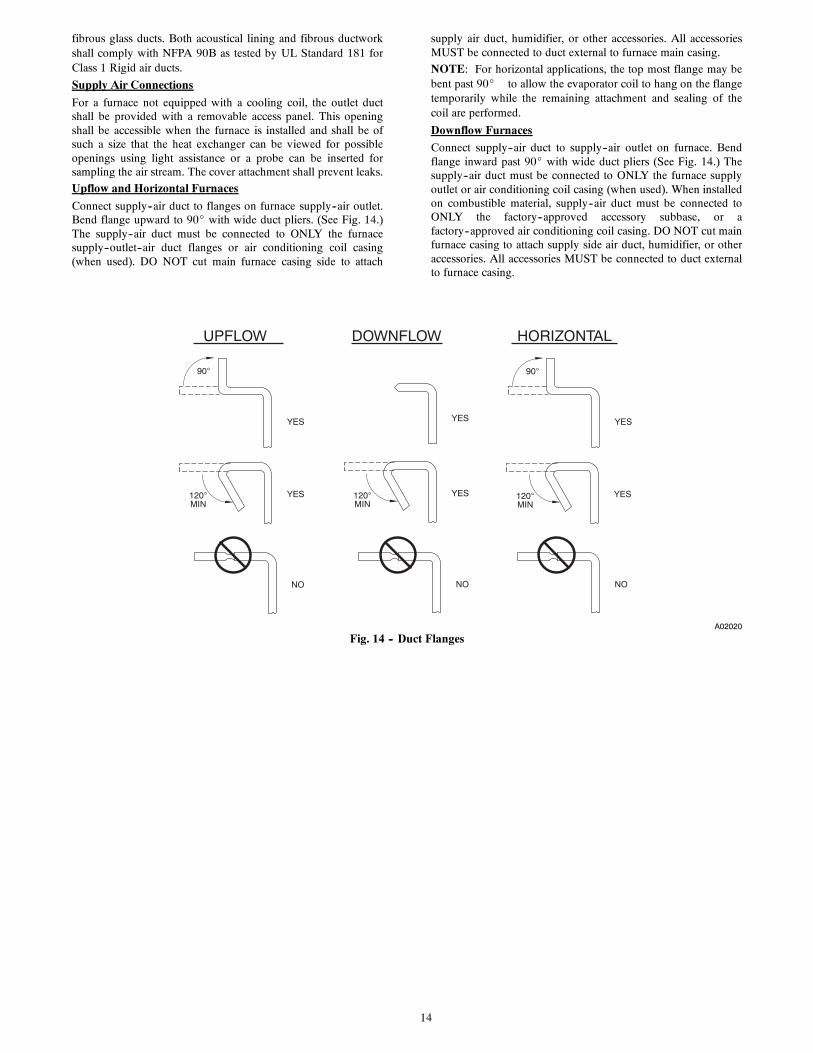
Supply Air Connections
For a furnace not equipped with a cooling coil, the outlet ductshall be provided with a removable access panel. This openingshall be accessible when the furnace is installed and shall be ofsuch a size that the heat exchanger can be viewed for possibleopenings using light assistance or a probe can be inserted forsampling the air stream. The cover attachment shall prevent leaks.
Upflow and Horizontal Furnaces
Connect supply--air duct to flanges on furnace supply--air outlet.Bend flange upward to 90_ with wide duct pliers. (See Fig. 14.)The supply--air duct must be connected to ONLY the furnacesupply--outlet--air duct flanges or air conditioning coil casing(when used). DO NOT cut main furnace casing side to attach
supply air duct, humidifier, or other accessories. All accessoriesMUST be connected to duct external to furnace main casing.
NOTE: For horizontal applications, the top most flange may bebent past 90_ to allow the evaporator coil to hang on the flangetemporarily while the remaining attachment and sealing of thecoil are performed.
Downflow Furnaces
Connect supply--air duct to supply--air outlet on furnace. Bendflange inward past 90_ with wide duct pliers (See Fig. 14.) Thesupply--air duct must be connected to ONLY the furnace supplyoutlet or air conditioning coil casing (when used). When installedon combustible material, supply--air duct must be connected toONLY the factory--approved accessory subbase, or afactory--approved air conditioning coil casing. DO NOT cut mainfurnace casing to attach supply side air duct, humidifier, or otheraccessories. All accessories MUST be connected to duct externalto furnace casing.
UPFLOW DOWNFLOW HORIZONTAL
YES
NO NO
YES
YES
YES
NO
120MIN
YES 120MIN
YES120MIN
90 90
A02020
Fig. 14 -- Duct Flanges

15
1 / 4 " (6mm) THREADED ROD4 REQ.
SECURE ANGLEIRON TO BOTTOMOF FURNACE WITH3 #8 x 3/4" (19mm) SCREWSTYPICAL FOR 2 SUPPORTS
1” (25mm) SQUARE, 1-1/4”x1-1/4”x1/8” (32x32x3mm)ANGLE IRON OR UNI-STRUT MAY BE USED
(2) HEX NUTS, (2) WASHERS & (2) LOCK WASHERSREQ. PER ROD
8" (203mm) MIN FOR DOOR REMOVAL
OUTER DOOR A S SEMBLY
A10130
Fig. 15 -- Horizontal Unit Suspension
METHOD 2USE (4) #8 x 3/4 (19 mm) SHEETMETAL SCREWS FOR EACHSTRAP. THE STRAPSSHOULD BE VERTICALAGAINST THE FURNACESIDES AND NOT PULL AWAYFROM THE FURNACESIDES.
METHOD 1FOLD ALL STRAPS UNDERFURNACE AND SECURE WTH(4) #8 x 3/4 (19 mm) SHEET METAL SCREWS (2 SCREWS IN SIDE AND 2 SCREWSIN BOTTOM).
A10131
Fig. 16 -- Horizontal Suspension with Straps

16
30-IN . (762mm) MIN WORK AREA
6 ″ M IN *
TYPE-B VENT
17 3 / 4 ″
22 ″
SHEET MET AL
SEDIMENT TRAP
EQUIPMENT MANU AL SHUT -OFF GAS VA LV E
LINE CONT A CT ONL Y PERMISSIBLE BETWEEN LINES FORMED BY INTERSECTIONS OF THE T OP AND TW O SIDES OF THE FURNA CE JA CKET AND BUILDING JOISTS , STUDS , OR FRAMING.
GAS ENTR Y
17 3 / 4 ″ (451mm)OVERALL4 3 / 4 ″ (121mm) UNDER DOOR1 ″ (25mm) UNDER FURNACE
EXTEND OUT 12 ″ (305mm)FR OM FA CE OF DOOR
* WHEN USED W ITH SINGLE W ALL VEN T CONNECTIONS
UNION
(152mm)
(451mm)
(559mm)
A10164
Fig. 17 -- Typical Attic Installation
A190054
Fig. 18 -- Upflow Return Air Configurations and Restrictions
17
DOWNFLOW RETURN AIR CONFIGURATIONS AND RESTRICTIONS
A02163
Fig. 19 -- Downflow Return Air Configurations and Restrictions
A02162
Fig. 20 -- Horizontal Return Air Configurations and Restrictions

18
Table 4 – Air Delivery -- CFM (With Filter)*
COOLING4 AND HEATING AIR DELIVERY - CFM (Bottom Return5 With Filter)(SW1-5 and SW2-2 set to OFF, except as indicated. See notes 1 and 2.)
Unit Size: 045V14-12 Clg/CF Switch settings External Static Pressure (ESP)
Clg Switches: SW2-8 SW2-7 SW2-6 0.1 0.2 0.3 0.4 0.5 0.6 0.7 0.8 0.9 1.0
Clg Default: OFF OFF OFF 1190 1140 1100 1065 1020 985 905 800 665 525
Cooling(SW2-8,7,6)
OFF OFF ON 620 560 520 455 410 355 305 255 See note 4OFF ON OFF 795 755 705 670 615 585 530 490 440 405OFF ON ON 1020 955 930 890 840 805 755 715 645 490ON OFF OFF 1190 1140 1100 1065 1020 985 905 800 665 525ON OFF ON 1455 1390 1325 1255 1175 1085 1000 880 755 575ON ON OFF 1455 1390 1325 1255 1175 1085 1000 880 755 575ON ON ON 1455 1390 1325 1255 1175 1085 1000 880 755 575Maximum Clg Airflow2 1455 1390 1325 1255 1175 1085 1000 880 755 575
CF Switches SW2-5 SW2-4 SW2-3
Low-Clg Default: OFF OFF OFF 620 560 520 455 410 355 305 255 See note 4
Low-Cooling(SW2-5,4,3)
OFF OFF ON 620 560 520 455 410 355 305 255 See note 4OFF ON OFF 795 755 705 670 615 585 530 490 440 405OFF ON ON 1020 955 930 890 840 805 755 715 645 490ON OFF OFF 1190 1140 1100 1065 1020 985 905 800 665 525ON OFF ON 1455 1390 1325 1255 1175 1085 1000 880 755 575ON ON OFF 1455 1390 1325 1255 1175 1085 1000 880 755 575ON ON ON 1455 1390 1325 1255 1175 1085 1000 880 755 575
Cont. Fan Default: OFF OFF OFF 620 560 520 455 410 355 305 255 See note 4
Continuous Fan(SW2-5,4,3)
OFF OFF ON 620 560 520 455 410 355 305 255 See note 4OFF ON OFF 795 755 705 670 615 585 530 490 440 405OFF ON ON 1020 955 930 890 840 805 755 715 645 490ON OFF OFF 1020 955 930 890 840 805 755 715 645 490ON OFF ON 1020 955 930 890 840 805 755 715 645 490ON ON OFF 1020 955 930 890 840 805 755 715 645 490ON ON ON 1020 955 930 890 840 805 755 715 645 490
Heating(SW1)
High Heat Airflow3 915 860 825 790 735 700 650 610 550 450Low Heat Airflow3 780 730 685 635 585 545 495 450 400 370
Unit Size: 070V14-12 Clg/CF Switch settings External Static Pressure (ESP)
Clg Switches: SW2-8 SW2-7 SW2-6 0.1 0.2 0.3 0.4 0.5 0.6 0.7 0.8 0.9 1.0
Clg Default: OFF OFF OFF 1155 1125 1095 1065 1035 1005 975 950 915 875
Cooling(SW2-8,7,6)
OFF OFF ON 605 555 500 440 375 320 265 See note 4OFF ON OFF 775 735 690 650 600 550 500 450 405 365OFF ON ON 980 950 915 880 845 810 775 735 695 655ON OFF OFF 1155 1125 1095 1065 1035 1005 975 950 915 875ON OFF ON 1370 1340 1310 1285 1260 1235 1210 1140 1025 880ON ON OFF 1505 1480 1455 1420 1380 1335 1250 1155 1045 900ON ON ON 1505 1480 1455 1420 1380 1335 1250 1155 1045 900Maximum Clg Airflow2 1505 1480 1455 1420 1380 1335 1250 1155 1045 900
CF Switches SW2-5 SW2-4 SW2-3
Low-Clg Default: OFF OFF OFF 605 555 500 440 375 320 265 See note 4
Low-Cooling(SW2-5,4,3)
OFF OFF ON 605 555 500 440 375 320 265 See note 4OFF ON OFF 775 735 690 650 600 550 500 450 405 365OFF ON ON 980 950 915 880 845 810 775 735 695 655ON OFF OFF 1155 1125 1095 1065 1035 1005 975 950 915 875ON OFF ON 1370 1340 1310 1285 1260 1235 1210 1140 1025 880ON ON OFF 1505 1480 1455 1420 1380 1335 1250 1155 1045 900ON ON ON 1505 1480 1455 1420 1380 1335 1250 1155 1045 900
Cont. Fan Default: OFF OFF OFF 605 555 500 440 375 320 265 See note 4
Continuous Fan(SW2-5,4,3)
OFF OFF ON 605 555 500 440 375 320 265 See note 4OFF ON OFF 775 735 690 650 600 550 500 450 405 365OFF ON ON 980 950 915 880 845 810 775 735 695 655ON OFF OFF 1155 1125 1095 1065 1035 1005 975 950 915 875ON OFF ON 1370 1340 1310 1285 1260 1235 1210 1140 1025 880ON ON OFF 1370 1340 1310 1285 1260 1235 1210 1140 1025 880ON ON ON 1370 1340 1310 1285 1260 1235 1210 1140 1025 880
Heating(SW1)
High Heat Airflow3 1190 1160 1130 1100 1070 1045 1015 985 955 900
Low Heat Airflow3 725 680 635 585 530 475 425 375 330 285

19
Table 4 -- Air Delivery -- CFM (With Filter)* (CONTINUED)COOLING4 AND HEATING AIR DELIVERY - CFM (Bottom Return5 With Filter)
(SW1-5 and SW2-2 set to OFF, except as indicated. See notes 1 and 2.)
Unit Size: 070V17-16 Clg/CF Switch settings External Static Pressure (ESP)
Clg Switches: SW2-8 SW2-7 SW2-6 0.1 0.2 0.3 0.4 0.5 0.6 0.7 0.8 0.9 1.0
Clg Default: OFF OFF OFF 1600 1570 1535 1500 1465 1430 1400 1365 1335 1300
Cooling(SW2-8,7,6)
OFF OFF ON 590 520 440 365 300 235 See note 4OFF ON OFF 790 730 670 610 550 485 430 380 330 275OFF ON ON 1025 980 930 880 835 785 735 690 635 590ON OFF OFF 1230 1190 1150 1105 1065 1025 980 940 900 860ON OFF ON 1390 1355 1315 1280 1240 1200 1165 1125 1090 1055ON ON OFF 1600 1570 1535 1500 1465 1430 1400 1365 1335 1300ON ON ON 1855 1830 1800 1770 1740 1695 1645 1600 1520 1415Maximum Clg Airflow2 1855 1830 1800 1770 1740 1695 1645 1600 1520 1415
CF Switches SW2-5 SW2-4 SW2-3
Low-Clg Default: OFF OFF OFF 590 520 440 365 300 235 See note 4
Low-Cooling(SW2-5,4,3)
OFF OFF ON 590 520 440 365 300 235 See note 4OFF ON OFF 790 730 670 610 550 485 430 380 330 275OFF ON ON 1025 980 930 880 835 785 735 690 635 590ON OFF OFF 1230 1190 1150 1105 1065 1025 980 940 900 860ON OFF ON 1390 1355 1315 1280 1240 1200 1165 1125 1090 1055ON ON OFF 1600 1570 1535 1500 1465 1430 1400 1365 1335 1300ON ON ON 1855 1830 1800 1770 1740 1695 1645 1600 1520 1415
Cont. Fan Default: OFF OFF OFF 590 520 440 365 300 235 See note 4
Continuous Fan(SW2-5,4,3)
OFF OFF ON 590 520 440 365 300 235 See note 4OFF ON OFF 685 625 565 505 445 385 325 265 See note 4OFF ON ON 790 730 670 610 550 485 430 380 330 275ON OFF OFF 790 730 670 610 550 485 430 380 330 275ON OFF ON 790 730 670 610 550 485 430 380 330 275ON ON OFF 790 730 670 610 550 485 430 380 330 275ON ON ON 790 730 670 610 550 485 430 380 330 275
Heating(SW1)
High Heat Airflow3 1410 1375 1340 1300 1260 1225 1190 1155 1120 1085Low Heat Airflow3 1235 1195 1155 1110 1070 1025 985 945 905 865
Unit Size: 090V17-16 Clg/CF Switch settings External Static Pressure (ESP)
Clg Switches: SW2-8 SW2-7 SW2-6 0.1 0.2 0.3 0.4 0.5 0.6 0.7 0.8 0.9 1.0
Clg Default: OFF OFF OFF 1560 1520 1485 1450 1415 1380 1340 1300 1260 1115
Cooling(SW2-8,7,6)
OFF OFF ON 680 605 495 415 345 275 See note 4OFF ON OFF 835 770 700 600 535 465 410 350 285 240OFF ON ON 1035 980 930 870 795 720 665 605 555 505ON OFF OFF 1210 1165 1125 1080 1030 975 905 845 790 740ON OFF ON 1375 1335 1300 1260 1220 1175 1125 1075 1010 955ON ON OFF 1560 1520 1485 1450 1415 1380 1340 1300 1260 1115ON ON ON 1640 1605 1570 1540 1505 1470 1435 1390 1325 1110Maximum Clg Airflow2 1640 1605 1570 1540 1505 1470 1435 1390 1325 1110
CF Switches SW2-5 SW2-4 SW2-3
Low-Clg Default: OFF OFF OFF 680 605 495 415 345 275 See note 4
Low-Cooling(SW2-5,4,3)
OFF OFF ON 680 605 495 415 345 275 See note 4OFF ON OFF 835 770 700 600 535 465 410 350 285 240OFF ON ON 1035 980 930 870 795 720 665 605 555 505ON OFF OFF 1210 1165 1125 1080 1030 975 905 845 790 740ON OFF ON 1375 1335 1300 1260 1220 1175 1125 1075 1010 955ON ON OFF 1560 1520 1485 1450 1415 1380 1340 1300 1260 1115ON ON ON 1640 1605 1570 1540 1505 1470 1435 1390 1325 1110
Cont. Fan Default: OFF OFF OFF 680 605 495 415 345 275 See note 4
Continuous Fan(SW2-5,4,3)
OFF OFF ON 680 605 495 415 345 275 See note 4OFF ON OFF 835 770 700 600 535 465 410 350 285 240OFF ON ON 1035 980 930 870 795 720 665 605 555 505ON OFF OFF 1210 1165 1125 1080 1030 975 905 845 790 740ON OFF ON 1375 1335 1300 1260 1220 1175 1125 1075 1010 955ON ON OFF 1560 1520 1485 1450 1415 1380 1340 1300 1260 1115ON ON ON 1560 1520 1485 1450 1415 1380 1340 1300 1260 1115
Heating(SW1)
High Heat Airflow3 1400 1360 1325 1285 1245 1200 1155 1110 1045 995
Low Heat Airflow3 1035 980 930 870 795 720 665 605 555 505

20
Table 4 -- Air Delivery -- CFM (With Filter)* (CONTINUED)COOLING4 AND HEATING AIR DELIVERY - CFM (Bottom Return5 With Filter)
(SW1-5 and SW2-2 set to OFF, except as indicated. See notes 1 and 2.)
Unit Size: 090V21-20 Clg/CF Switch settings External Static Pressure (ESP)
Clg Switches: SW2-8 SW2-7 SW2-6 0.1 0.2 0.3 0.4 0.5 0.6 0.7 0.8 0.9 1.0
Clg Default: OFF OFF OFF 1985 1935 1885 1835 1785 1735 1685 1630 1583 1532
Cooling(SW2-8,7,6)
OFF OFF ON 860 755 650 545 445 350 235 See note 4OFF ON OFF 1085 1000 910 830 735 655 565 485 405 310OFF ON ON 1255 1180 1105 1025 950 870 790 715 640 570ON OFF OFF 1425 1355 1290 1220 1150 1085 1015 940 870 800ON OFF ON 1630 1575 1515 1455 1395 1330 1270 1210 1155 1090ON ON OFF 1985 1935 1885 1835 1785 1735 1685 1630 1583 1532ON ON ON 2100 2055 2010 1960 1915 1870 1820 1775 1715 1640Maximum Clg Airflow2 2100 2055 2010 1960 1915 1870 1820 1775 1715 1640
CF Switches SW2-5 SW2-4 SW2-3
Low-Clg Default: OFF OFF OFF 860 755 650 545 445 350 235 See note 4
Low-Cooling(SW2-5,4,3)
OFF OFF ON 700 575 455 345 225 See note 4OFF ON OFF 860 755 650 545 445 350 235 See note 4OFF ON ON 1085 1000 910 830 735 655 565 485 405 310ON OFF OFF 1255 1180 1105 1025 950 870 790 715 640 570ON OFF ON 1425 1355 1290 1220 1150 1085 1015 940 870 800ON ON OFF 1630 1575 1515 1455 1395 1330 1270 1210 1155 1090ON ON ON 1985 1935 1885 1835 1785 1735 1685 1630 1583 1532
Cont. Fan Default: OFF OFF OFF 860 755 650 545 445 350 235 See note 4
Continuous Fan(SW2-5,4,3)
OFF OFF ON 700 575 455 345 225 See note 4OFF ON OFF 860 755 650 545 445 350 235 See note 4OFF ON ON 1085 1000 910 830 735 655 565 485 405 310ON OFF OFF 1255 1180 1105 1025 950 870 790 715 640 570ON OFF ON 1255 1180 1105 1025 950 870 790 715 640 570ON ON OFF 1255 1180 1105 1025 950 870 790 715 640 570ON ON ON 1255 1180 1105 1025 950 870 790 715 640 570
Heating(SW1)
High Heat Airflow3 1830 1775 1725 1675 1625 1570 1520 1465 1410 1360Low Heat Airflow3 1600 1540 1485 1430 1370 1315 1255 1195 1140 1070
Unit Size: 110V21-22 Clg/CF Switch settings External Static Pressure (ESP)
Clg Switches: SW2-8 SW2-7 SW2-6 0.1 0.2 0.3 0.4 0.5 0.6 0.7 0.8 0.9 1.0
Clg Default: OFF OFF OFF 2055 2000 1950 1900 1840 1790 1740 1675 1625 1565
Cooling(SW2-8,7,6)
OFF OFF ON 855 755 See note 4OFF ON OFF 1060 985 875 800 700 See note 4OFF ON ON 1250 1180 1095 1025 925 860 775 715 See note 4ON OFF OFF 1445 1380 1320 1235 1175 1100 1035 955 900 825ON OFF ON 1685 1630 1560 1505 1445 1375 1320 1265 1195 1140ON ON OFF 2055 2000 1950 1900 1840 1790 1740 1675 1625 1565ON ON ON 2465 2415 2365 2305 2230 2140 2045 1925 1805 1655Maximum Clg Airflow2 2465 2415 2365 2305 2230 2140 2045 1925 1805 1655
CF Switches SW2-5 SW2-4 SW2-3
Low-Clg Default: OFF OFF OFF 855 755 See note 4
Low-Cooling(SW2-5,4,3)
OFF OFF ON 640 540 See note 4OFF ON OFF 855 755 See note 4OFF ON ON 1060 985 875 800 700 See note 4ON OFF OFF 1250 1180 1095 1025 925 860 775 715 See note 4ON OFF ON 1445 1380 1320 1235 1175 1100 1035 955 900 825ON ON OFF 1685 1630 1560 1505 1445 1375 1320 1265 1195 1140ON ON ON 2055 2000 1950 1900 1840 1790 1740 1675 1625 1565
Cont. Fan Default: OFF OFF OFF 855 755 See note 4
Continuous Fan(SW2-5,4,3)
OFF OFF ON 640 540 See note 4OFF ON OFF 855 755 See note 4OFF ON ON 1060 985 875 800 700 See note 4ON OFF OFF 1250 1180 1095 1025 925 860 775 715 See note 4ON OFF ON 1445 1380 1320 1235 1175 1100 1035 955 900 825ON ON OFF 1445 1380 1320 1235 1175 1100 1035 955 900 825ON ON ON 1445 1380 1320 1235 1175 1100 1035 955 900 825
Heating(SW1)
High Heat Airflow3 2105 2055 2005 1955 1895 1850 1795 1735 1665 1580
Low Heat Airflow3 1740 1685 1620 1560 1505 1440 1385 1325 1260 1205

21
Table 4 -- Air Delivery -- CFM (With Filter)* (CONTINUED)COOLING4 AND HEATING AIR DELIVERY - CFM (Bottom Return5 With Filter)
(SW1-5 and SW2-2 set to OFF, except as indicated. See notes 1 and 2.)
Unit Size: 135V24-22 Clg/CF Switch settings External Static Pressure (ESP)
Clg Switches: SW2-8 SW2-7 SW2-6 0.1 0.2 0.3 0.4 0.5 0.6 0.7 0.8 0.9 1.0
Clg Default: OFF OFF OFF 2105 2050 1995 1940 1880 1820 1765 1705 1650 1590
Cooling(SW2-8,7,6)
OFF OFF ON 990 885 780 665 570 See note 4OFF ON OFF 1180 1090 995 900 815 715 635 555 475 400OFF ON ON 1355 1270 1190 1105 1020 940 855 775 700 630ON OFF OFF 1535 1465 1395 1320 1245 1165 1095 1025 945 875ON OFF ON 1735 1670 1605 1535 1470 1405 1335 1270 1205 1140ON ON OFF 2105 2050 1995 1940 1880 1820 1765 1705 1650 1590ON ON ON 2280 2225 2175 2120 2065 2010 1955 1905 1850 1800Maximum Clg Airflow2 2360 2310 2265 2215 2160 2115 2060 2010 1960 1870
CF Switches SW2-5 SW2-4 SW2-3
Low-Clg Default: OFF OFF OFF 990 885 780 665 570 See note 4
Low-Cooling(SW2-5,4,3)
OFF OFF ON 800 670 540 410 280 See note 4OFF ON OFF 990 885 780 665 570 See note 4OFF ON ON 1180 1090 995 900 815 715 635 555 475 400ON OFF OFF 1355 1270 1190 1105 1020 940 855 775 700 630ON OFF ON 1535 1465 1395 1320 1245 1165 1095 1025 945 875ON ON OFF 1735 1670 1605 1535 1470 1405 1335 1270 1205 1140ON ON ON 2105 2050 1995 1940 1880 1820 1765 1705 1650 1590
Cont. Fan Default: OFF OFF OFF 740 605 470 360 255 See note 4
Continuous Fan(SW2-5,4,3)
OFF OFF ON 740 605 470 360 255 See note 4OFF ON OFF 900 775 650 525 400 See note 4OFF ON ON 1080 980 885 785 680 595 510 430 345 260ON OFF OFF 1080 980 885 785 680 595 510 430 345 260ON OFF ON 1080 980 885 785 680 595 510 430 345 260ON ON OFF 1080 980 885 785 680 595 510 430 345 260ON ON ON 1080 980 885 785 680 595 510 430 345 260
Heating(SW1)
High Heat Airflow3 2130 2075 2020 1970 1910 1855 1805 1745 1690 1630
Low Heat Airflow3 1855 1795 1730 1670 1605 1545 1480 1420 1360 1300
1. Nominal 350 CFM/ton cooling airflow is delivered with SW1-5 and SW2-2 set to OFF.Set both SW1-5 and SW2-2 to ON for +7% airflow (nominal 370 CFM/ton).Set SW1-5 to ON and SW2-2 to OFF for +15% airflow (nominal 400 CFM/ton).Set SW2-2 to ON and SW1-5 to OFF for -7% airflow (nominal 325 CFM/ton).The above adjustments in airflow are subject to motor horsepower range/capacity.This applies to Cooling and Low-Cooling airflow, but does not affect continuous fan airflow.
2. Maximum cooling airflow is achieved when switches SW2-6, SW2-7, SW2-8 and SW1-5 are set to ON, and SW2-2 is set to OFF.
3. All heating CFM's are when comfort/efficiency adjustment switch (SW1-4) is set to OFF
4. Ductwork must be sized for high-heating CFM within the operational range of ESP. Operation within the blank areas of the chart is notrecommended because high-heat operation will be above 1.0 ESP.
5. All airflows on 21" casing size furnaces are 5% less on side return only installations.
6. Side returns for 24.5" casing sizes require two sides, or side and bottom, to allow sufficient airflow at the return of the furnace.
7. Airflows over 1800 CFM require bottom return, two-side return, or bottom and side return or excessive watt draw may result. A minimumfilter size of 20x25" (508 x 635 mm) is required.
22
Return Air Connections
FIRE HAZARD
A failure to follow this warning could cause personal injury,death and/or property damage.
Never connect return--air ducts to the back of the furnace.Follow instructions below.
! WARNING
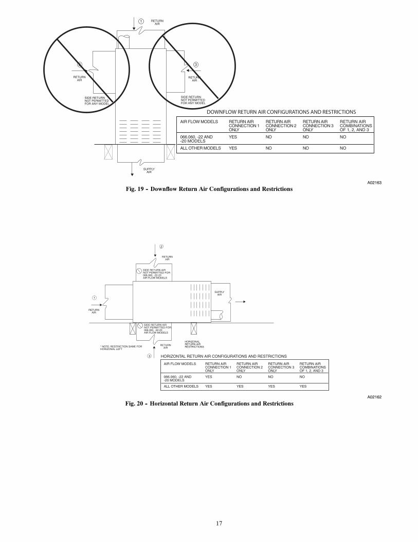
Downflow Furnaces
The return--air duct must be connected to return--air opening(bottom inlet). DO NOT cut into casing sides (left or right). Sideopening is permitted for only upflow and certain horizontalfurnaces. Bypass humidifier connections should be made atductwork or coil casing sides exterior to furnace. (See Fig. 19.)
Upflow and Horizontal Furnaces
The return--air duct must be connected to bottom, sides (left orright), or a combination of bottom and side(s) of main furnacecasing. Bypass humidifier may be attached into unused return airside of the furnace casing. (See Fig. 18 and 20.) Not all upflowand horizontal furnace models are approved for side return airconnections. (See Fig. 18 and 20.)
GAS PIPING
FIRE OR EXPLOSION HAZARD
Failure to follow this warning could result in personalinjury, death, and/or property damage.
Never purge a gas line into a combustion chamber. Nevertest for gas leaks with an open flame. Use a commerciallyavailable soap solution made specifically for the detectionof leaks to check all connections. A fire or explosion mayresult causing property damage, personal injury or loss oflife.
! WARNING
FIRE OR EXPLOSION HAZARD
Failure to follow this warning could result in personalinjury, death, and/or property damage.
Use proper length of pipe to avoid stress on gas controlmanifold and a gas leak.
! WARNING
FIRE OR EXPLOSION HAZARD
Failure to follow this warning could result in personalinjury, death, and/or property damage.
Gas valve inlet and/or inlet pipe must remain capped untilgas supply line is permanently installed to protect the valvefrom moisture and debris. Also, install a sediment trap in thegas supply piping at the inlet to the gas valve.
! WARNING
Gas piping must be installed in accordance with national andlocal codes. Refer to current edition of NFGC in the U.S.
Installations must be made in accordance with all authoritieshaving jurisdiction. If possible, the gas supply line should be aseparate line running directly from meter to furnace.
NOTE: In the state of Massachusetts:
1. Gas supply connections MUST be performed by a li-censed plumber or gas fitter.
2. When flexible connectors are used, the maximum lengthshall not exceed 36 in. (915 mm).
3. When lever handle type manual equipment shutoff valvesare used, they shall be T--handle valves.
4. The use of copper tubing for gas piping is NOT approvedby the state of Massachusetts.
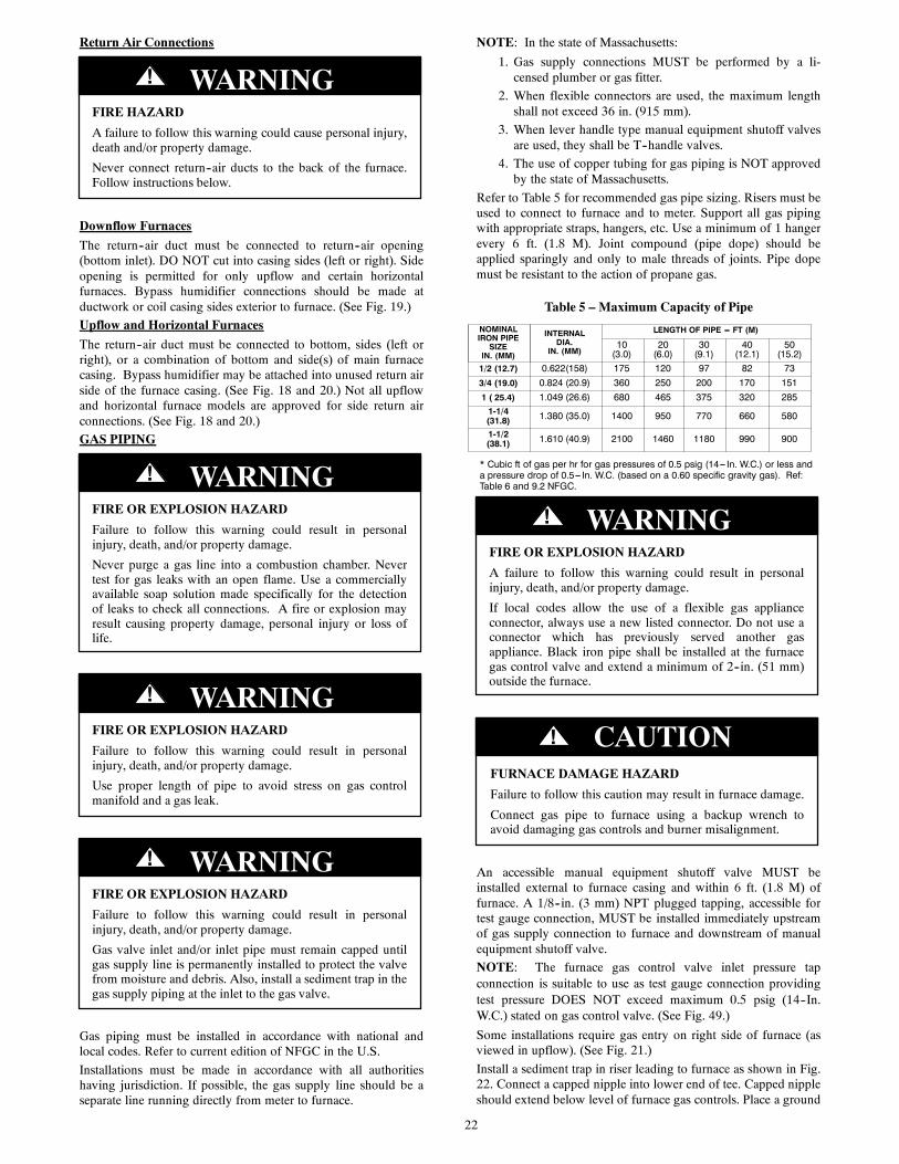
Refer to Table 5 for recommended gas pipe sizing. Risers must beused to connect to furnace and to meter. Support all gas pipingwith appropriate straps, hangers, etc. Use a minimum of 1 hangerevery 6 ft. (1.8 M). Joint compound (pipe dope) should beapplied sparingly and only to male threads of joints. Pipe dopemust be resistant to the action of propane gas.
Table 5 – Maximum Capacity of Pipe
NOMINALIRON PIPESIZEIN. (MM)
INTERNALDIA.
IN. (MM)
LENGTH OF PIPE --- FT (M)
10(3.0)
20(6.0)
30(9.1)
40(12.1)
50(15.2)
1/2 (12.7) 0.622(158) 175 120 97 82 733/4 (19.0) 0.824 (20.9) 360 250 200 170 1511 ( 25.4) 1.049 (26.6) 680 465 375 320 2851-1/4(31.8) 1.380 (35.0) 1400 950 770 660 580
1-1/2(38.1) 1.610 (40.9) 2100 1460 1180 990 900
* Cubic ft of gas per hr for gas pressures of 0.5 psig (14--- In. W.C.) or less anda pressure drop of 0.5--- In. W.C. (based on a 0.60 specific gravity gas). Ref:Table 6 and 9.2 NFGC.
FIRE OR EXPLOSION HAZARD
A failure to follow this warning could result in personalinjury, death, and/or property damage.
If local codes allow the use of a flexible gas applianceconnector, always use a new listed connector. Do not use aconnector which has previously served another gasappliance. Black iron pipe shall be installed at the furnacegas control valve and extend a minimum of 2--in. (51 mm)outside the furnace.
! WARNING
FURNACE DAMAGE HAZARD
Failure to follow this caution may result in furnace damage.
Connect gas pipe to furnace using a backup wrench toavoid damaging gas controls and burner misalignment.
CAUTION!
An accessible manual equipment shutoff valve MUST beinstalled external to furnace casing and within 6 ft. (1.8 M) offurnace. A 1/8--in. (3 mm) NPT plugged tapping, accessible fortest gauge connection, MUST be installed immediately upstreamof gas supply connection to furnace and downstream of manualequipment shutoff valve.
NOTE: The furnace gas control valve inlet pressure tapconnection is suitable to use as test gauge connection providingtest pressure DOES NOT exceed maximum 0.5 psig (14--In.W.C.) stated on gas control valve. (See Fig. 49.)
Some installations require gas entry on right side of furnace (asviewed in upflow). (See Fig. 21.)
Install a sediment trap in riser leading to furnace as shown in Fig.22. Connect a capped nipple into lower end of tee. Capped nippleshould extend below level of furnace gas controls. Place a ground

23
joint union between furnace gas control valve and exteriormanual equipment gas shutoff valve.
A 1/8--in. (3 mm) NPT plugged tapping, accessible for test gaugeconnection, MUST be installed immediately upstream of gassupply connection to furnace and downstream of manualequipment shutoff valve.
Piping should be pressure and leak tested in accordance with thecurrent addition of the NFGC in the United States, local, andnational plumbing and gas codes before the furnace has beenconnected. After all connections have been made, purge lines andcheck for leakage at furnace prior to operating furnace.
If pressure exceeds 0.5 psig (14--In. W.C.), gas supply pipe mustbe disconnected from furnace and capped before and duringsupply pipe pressure test. If test pressure is equal to or less than0.5 psig (14--In. W.C.), turn off electric shutoff switch located onfurnace gas control valve and accessible manual equipmentshutoff valve before and during supply pipe pressure test. Afterall connections have been made, purge lines and check forleakage at furnace prior to operating furnace.
The gas supply pressure shall be within the maximum andminimum inlet supply pressures marked on the rating plate withthe furnace burners ON and OFF.
2” (51mm)
Street Elbow
A08551
Fig. 21 -- Burner and Manifold
UNION
SEDIMENTTRAP
MANUALSHUTOFFVALVE(REQUIRED)
GASSUPPLY
A02035
Fig. 22 -- Typical Gas Pipe Arrangement
ELECTRICAL CONNECTIONS
ELECTRICAL SHOCK, FIRE OR EXPLOSIONHAZARD
Failure to follow safety warnings could result indangerous operation, serious injury, death or propertydamage.
Improper servicing could result in dangerous operation,serious injury, death or property damage.
-- Before servicing, disconnect all electrical power tofurnace.
-- When servicing controls, label all wires prior todisconnection. Reconnect wires correctly.
-- Verify proper operation after servicing.
! WARNING
ELECTRICAL SHOCK HAZARD
Failure to follow this warning could result in personalinjury or death.
Blower access panel door switch opens 115--v power tocontrol. No component operation can occur. Do notbypass or close switch with panel removed.
! WARNING
See Fig. 25 for field wiring diagram showing typical field 115--vwiring. Check all factory and field electrical connections fortightness.
Field--supplied wiring shall conform with the limitations of 63_F(33_C) rise.
ELECTRICAL SHOCK AND FIRE HAZARD
Failure to follow this warning could result in personalinjury, death, or property damage.
The cabinet MUST have an uninterrupted or unbrokenground according to NEC NFPA 70 or local codes tominimize personal injury if an electrical fault should occur.This may consist of electrical wire, conduit approved forelectrical ground or a listed, grounded power cord (wherepermitted by local code) when installed in accordance withexisting electrical codes. Refer to the power cordmanufacturer’s ratings for proper wire gauge. Do not usegas piping as an electrical ground.
! WARNING
FURNACE MAY NOT OPERATE HAZARD
Failure to follow this caution may result in intermittentfurnace operation.
Furnace control must be grounded for proper operation orelse control will lock out. Control must remain groundedthrough green/yellow wire routed to gas valve and manifoldbracket screw.
CAUTION!

24
Table 6 – Electrical Data
FURNACE SIZEVOLTS -HERTZ -PHASE
OPERATING VOLTAGERANGE * MAX. UNIT
AMPSUNIT
AMPACITY#
MAX WIRELENGTHFT (M)‡
MAX. FUSEOR CKT.BKR AMPS
†
MIN. WIREGAUGE
Max. Min.
045V14---12 115-60-1 127 104 7.7 10.4 35 (10.9) 15 14070V14---12 115-60-1 127 104 8.0 10.8 34 (10.4) 15 14070V17---16 115-60-1 127 104 10.5 13.9 26 (8.1) 15 14090V17---16 115-60-1 127 104 8.6 11.3 32 (10) 15 14090V21---20 115-60-1 127 104 11.5 15.0 24 (7.5) 15 14110V21---22 115-60-1 127 104 13.1 16.9 34 (10.4) 20 12135V24---22 115-60-1 127 104 13.9 17.9 32 (9.8) 20 12
* Permissible limits of the voltage range at which the unit operates satisfactorily.# Unit ampacity = 125 percent of largest operating component’s full load amps plus 100 percent of all other potential operating components’ (EAC, humidifier,etc.) full load amps.{Time---delay type is recommended.}Length shown is as measured 1 way along wire path between furnace and service panel for maximum 2 percent voltage drop.
115--V Wiring
Verify that the voltage, frequency, and phase correspond to thatspecified on unit rating plate. Also, check to be sure that serviceprovided by utility is sufficient to handle load imposed by thisequipment. Refer to rating plate or Table 6 for equipmentelectrical specifications.
U.S. Installations: Make all electrical connections in accordancewith National Electrical Code (NEC) NFPA 70 and any localcodes or ordinances that might apply.
FIRE HAZARD
Failure to follow this warning could result in personalinjury, death, or property damage.
Do not connect aluminum wire between disconnectswitch and furnace. Use only copper wire.
! WARNING
Use a separate, fused branch electrical circuit with a properlysized fuse or circuit breaker for this furnace. See Table 6 for wiresize and fuse specifications. A readily accessible means ofelectrical disconnect must be located within sight of the furnace.
NOTE: Proper polarity must be maintained for 115--v wiring. Ifpolarity is incorrect, control LED status indicator light will flashrapidly and furnace will NOT operate.
J--Box Relocation
NOTE: If factory location of J--Box is acceptable, go to nextsection (ELECTRICAL CONNECTION to J--Box).
NOTE: On 14--in. (356 mm) wide casing models, the J--Boxshall not be relocated to other side of furnace casing when thevent pipe is routed within the casing.
1. Remove and save two screws holding J--Box. (See Fig.23.)
NOTE: The J--Box cover need not be removed from the J--Boxin order to move the J--Box. Do NOT remove green groundscrew inside J--Box. (See Fig. 23.)
2. Cut wire tie on loop in furnace wires attached to J--Box.
3. Move J--Box to desired location.
4. Fasten J--Box to casing with the two screws removed inStep 1.
5. Route J--Box wires within furnace away from sharp edges,rotating parts and hot surfaces.
Electrical Connection to J--Box
Electrical Box on Furnace Casing Side (See Fig. 24.)
FIRE OR ELECTRICAL SHOCK HAZARD
Failure to follow this warning could result in personalinjury, death, or property damage.
If field--supplied manual disconnect switch is to be mountedon furnace casing side, select a location where a drill orfastener cannot damage electrical or gas components.
! WARNING
FactoryFactoryInstalledInstalled
AlternateAlternateLocationLocation
A10291
Fig. 23 -- Relocating J--Box
1. Select and remove a hole knockout in the casing where theelectrical box is to be installed.
NOTE: Check that duct on side of furnace will not interfere withinstalled electrical box.
2. Remove the desired electrical box hole knockout and posi-tion the hole in the electrical box over the hole in the fur-nace casing.
3. Fasten the electrical box to casing by driving two field--supplied screws from inside electrical box into casingsteel.
4. Remove and save two screws holding J--Box. (See Fig.23.)
5. Pull furnace power wires out of 1/2--in. (12 mm) diameterhole in J--Box. Do not loosen wires from strain--reliefwire--tie on outside of J--Box.

25
6. Route furnace power wires through holes in casing andelectrical box and into electrical box.
7. Pull field power wires into electrical box.
8. Remove cover from furnace J--Box.
9. Route field ground wire through holes in electrical boxand casing, and into furnace J--Box.
10. Reattach furnace J--Box to furnace casing with screws re-moved in Step 4.
11. Secure field ground wire to J--Box green ground screw.
12. Complete electrical box wiring and installation. Connectline voltage leads as shown in Fig. 24. Use best practices(NEC in U.S. for wire bushings, strain relief, etc.
13. Reinstall cover to J--Box. Do not pinch wires betweencover and bracket.
A10141
Fig. 24 -- Field--Supplied Electrical Box on Furnace Casing
Power Cord Installation in Furnace J--Box
NOTE: Power cords must be able to handle the electricalrequirements listed in Table 6. Refer to power cordmanufacturer’s listings.
1. Remove cover from J--Box.
2. Route listed power cord through 7/8--in. (22 mm) diameterhole in J--Box.
3. Secure power cord to J--Box bracket with a strain reliefbushing or a connector approved for the type of cord used.
4. Secure field ground wire to green ground screw on J--Boxbracket.
5. Connect line voltage leads as shown in Fig. 25.
6. Reinstall cover to J--Box. Do not pinch wires betweencover and bracket.
BX Cable Installation in Furnace J--Box
1. Remove cover from J--Box.
2. Route BX cable into 7/8--in. (22 mm) diameter hole inJ--Box.
3. Secure BX cable to J--Box bracket with connectors ap-proved for the type of cable used.
4. Secure field ground wire to green ground screw on J--Boxbracket.
5. Connect line voltage leads as shown in Fig. 25.
6. Reinstall cover to J--Box. Do not pinch wires betweencover and bracket.
24--V Wiring
Make field 24--v connections at the 24--v terminal strip. (See Fig.25 -- 34.) Connect terminal Y/Y2 as shown in Fig. 27--34 forproper cooling operation. Use only AWG No. 18, color--coded,copper thermostat wire.
The 24--v circuit contains an automotive--type, 3--amp. fuselocated on the control. Any direct shorts during installation,service, or maintenance could cause this fuse to blow. If fusereplacement is required, use ONLY a 3--amp. fuse of identicalsize.
ACCESSORIES
1. Electronic Air Cleaner (EAC)Connect an accessory Electronic Air Cleaner (if used) us-ing 1/4--in female quick connect terminals to the two male1/4--in quick--connect terminals on the control boardmarked EAC--1 and EAC--2. The terminals are rated for115VAC, 1.0 amps maximum and are energized duringblower motor operation. (See Fig. 26.)
2. Humidifier (HUM)Connect an accessory 24 VAC, 0.5 amp. maximum hu-midifier (if used) to the 1/4--in male quick--connect HUMterminal and COM--24V screw terminal on the controlboard thermostat strip. The HUM terminal is energizedwhen blower is energized in heating. (See Fig. 26.)
NOTE: DO NOT connect furnace control HUM terminal toHUM (humidifier) terminal on Thermidistat, Zone Controller orsimilar device. See ThermidistatE, Zone Controller, thermostat,or controller manufacturer’s instructions for proper connection.

26
115-VOLT FIELD-SUPPLIED
FUSEDDISCONNECT
JUNCTIONBOX
CONTROLBOX
24-VOLTTERMINALBLOCK
THREE-WIREHEATING-
ONLY
FIVEWIRE
NOTE 2
NOTE 1
1-STAGETHERMOSTATTERMINALS
FIELD-SUPPLIEDFUSED DISCONNECT
CONDENSINGUNIT
FURNACE
COM
R
W C Y R G
GND
GND
FIELD 24-VOLT WIRINGFIELD 115-, 208/230-, 460-VOLT WIRINGFACTORY 24-VOLT WIRINGFACTORY 115-VOLT WIRING
Connect Y/Y2-terminal as shown for proper operation.Some thermostats require a "C" terminal connection as shown.If any of the original wire, as supplied, must be replaced, usesame type or equivalent wire.
208/230- OR460-VOLTTHREEPHASE
208/230-VOLTSINGLEPHASE
WHT
BLK
WHT
BLK
W/W1
W2
Y/Y2
G
NOTES: 1.2.3.
A95236
Fig. 25 -- Field Wiring Diagram
A190044
Fig. 26 -- Variable Speed Furnace Control for ECM Blower Motor

27
VENTING
The furnace shall be connected to a listed factory built chimneyor vent, or a clay--tile lined masonry or concrete chimney. Ventinginto an unlined masonry chimney or concrete chimney isprohibited.
When an existing Category I furnace is removed or replaced, theoriginal venting system, may no longer be sized to properly ventthe attached appliances. An improperly sized Category I ventingsystem could cause the formation of condensate in the furnaceand vent, leakage of condensate and combustion products, andspillage of combustion products into the living space.
CARBONMONOXIDE POISONING HAZARD
Failure to follow the steps outlined below for eachappliance connected to the venting system being placed intooperation could result in carbon monoxide poisoning ordeath.
The following steps shall be followed for each applianceconnected to the venting system being placed intooperation, while all other appliances connected to theventing system are not in operation:
1. Seal any unused openings in venting system.
2. Inspect the venting system for proper size andhorizontal pitch, as required in the National Fuel GasCode, NFPA 54/ANSI Z223.1 and theseinstructions. Determine that there is no blockage orrestriction, leakage, corrosion and other deficiencies,which could cause an unsafe condition.
3. As far as practical, close all building doors andwindows and all doors between the space in whichthe appliance(s) connected to the venting system arelocated and other spaces of the building.
4. Close fireplace dampers.
5. Turn on clothes dryers and any appliance notconnected to the venting system. Turn on anyexhaust fans, such as range hoods and bathroomexhausts, so they are operating at maximum speed.Do not operate a summer exhaust fan.
6. Follow the lighting instructions. Place the appliancebeing inspected into operation. Adjust the thermostatso appliance is operating continuously.
7. Test for spillage from draft hood equippedappliances at the draft hood relief opening after 5minutes of main burner operation. Use the flame of amatch or candle.
8. If improper venting is observed during any of theabove tests, the venting system must be corrected inaccordance with the National Fuel Gas Code, NFPA54/ANSI Z223.1.
9. After it has been determined that each applianceconnected to the venting system properly vents whentested as outlined above, return doors, windows,exhaust fans, fireplace dampers and any othergas--fired burning appliance to their previousconditions of use.
! WARNING
Vent system or vent connectors may need to be resized. Ventsystems or vent connectors must be sized to approach minimumsize as determined using appropriate table found in the currentedition of NFGC.
General Venting Requirements
Follow all safety codes for proper vent sizing and installationrequirements, including local building codes, the National FuelGas Code NFPA 54/ANSI Z223.1 (NFGC), Parts 12 and 13 inthe United States, the local building codes, and furnace and ventmanufacturers’ instructions.
These furnaces are design--certified as Category I furnaces inaccordance with ANSI Z21.47/CSA 2.3 and operate with anon--positive vent static pressure to minimize the potential forvent gas leakage. Category I furnaces operate with a flue loss notless than 17% to minimize the potential for condensation in theventing system. These furnaces are approved for commonventing and multi--story venting with other fan assisted or drafthood equipped appliances in accordance with the NFCG, localbuilding codes, and furnace and vent manufacturers’ instructions.
The following information and warning must be considered inaddition to the requirements defined in the NFGC.
CARBON MONOXIDE POISONING HAZARD
Failure to follow this warning could result in personalinjury or death.
Do not bypass the draft safeguard switch, as an unsafecondition could exist which must be corrected.
! WARNING
1. If a vent (common or dedicated) becomes blocked, the fur-nace will be shut off by the draft safeguard switch locatedon the vent elbow.
2. Two--stage furnaces require Type B vent connectors out-side the casing in all configurations. Single wall vent con-nector may be used inside the furnace casing with thetransition to Type B vent outside the furnace casing. Sizethe connector so that the FAN--Min vent connector capa-city is equal to or lower than the low fire rate of the fur-nace and the FAN--Max vent connector capacity is equalto or higher than the furnace high fire rate.
3. Do not vent this Category I furnace into a single wall ded-icated or common vent. The dedicated or common vent isconsidered to be the vertical portion of the vent systemthat terminates outdoors.
4. Vent connectors serving Category I furnaces shall not beconnected into any portion of a mechanical draft systemoperating under positive pressure.
5. Do not vent this appliance with any solid fuel burning ap-pliance.
6. Category I furnaces must be vented vertically or nearlyvertically unless equipped with a listed mechanical venter.See SIDEWALL VENTING section.
7. Do not vent this appliance into an unlined masonry chim-ney. Refer to Chimney Inspection Chart, Fig. 35.

28
A00275
Fig. 27 -- Two--Stage Furnace with Single--SpeedAir Conditioner
See notes 2, 5, 8, 10, 11 and 12on the page following these figures
A03179
Fig. 28 -- Two--Stage Furnace with Two--Speed Air Condi-tioner
See notes 1, 2, 4, 6, 7, 9, 10, 11, and 15on the page following these figures
A03180
Fig. 29 -- Two--Stage Furnace with Single--Speed Heat Pump(Dual Fuel)
See notes 1, 2, 3, 4, 6, 8, 9, 10, 12, 13 and 15on the page following these figures
A03178
Fig. 30 -- Two--Stage Furnace with Two--Speed Heat Pump(Dual Fuel)

29
See notes 1, 2, 4, 11, 14, 15, and 16on the page following these figures
A03181
Fig. 31 -- Dual--Fuel Thermostat with Two--Stage Furnaceand Single--Speed Heat Pump
7
See notes 1, 2, 3, 4, 12, 13, 14, 15, and 17on the page following these figures
A03182
Fig. 32 -- Dual--Fuel Thermostat with Two--Stage Furnaceand Two--Speed Heat Pump
See notes 2, 11, and 12 on thepage following these figures
A03183
Fig. 33 -- Two--Stage Thermostat with Two--Stage Furnaceand Two--Speed Air Conditioner
See notes 1 and 2 on the pagefollowing these figures
A03184
Fig. 34 -- Single--Stage Thermostat with Two--Stage Furnaceand Two--Speed Air Conditioner
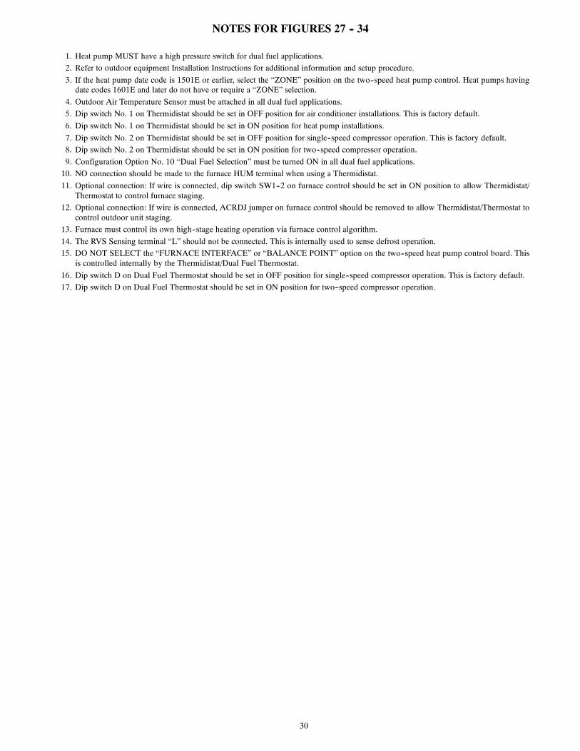
30
NOTES FOR FIGURES 27 -- 34
1. Heat pump MUST have a high pressure switch for dual fuel applications.
2. Refer to outdoor equipment Installation Instructions for additional information and setup procedure.
3. If the heat pump date code is 1501E or earlier, select the “ZONE” position on the two--speed heat pump control. Heat pumps havingdate codes 1601E and later do not have or require a “ZONE” selection.
4. Outdoor Air Temperature Sensor must be attached in all dual fuel applications.
5. Dip switch No. 1 on Thermidistat should be set in OFF position for air conditioner installations. This is factory default.
6. Dip switch No. 1 on Thermidistat should be set in ON position for heat pump installations.
7. Dip switch No. 2 on Thermidistat should be set in OFF position for single--speed compressor operation. This is factory default.
8. Dip switch No. 2 on Thermidistat should be set in ON position for two--speed compressor operation.
9. Configuration Option No. 10 “Dual Fuel Selection” must be turned ON in all dual fuel applications.
10. NO connection should be made to the furnace HUM terminal when using a Thermidistat.
11. Optional connection: If wire is connected, dip switch SW1--2 on furnace control should be set in ON position to allow Thermidistat/Thermostat to control furnace staging.
12. Optional connection: If wire is connected, ACRDJ jumper on furnace control should be removed to allow Thermidistat/Thermostat tocontrol outdoor unit staging.
13. Furnace must control its own high--stage heating operation via furnace control algorithm.
14. The RVS Sensing terminal “L” should not be connected. This is internally used to sense defrost operation.
15. DO NOT SELECT the “FURNACE INTERFACE” or “BALANCE POINT” option on the two--speed heat pump control board. Thisis controlled internally by the Thermidistat/Dual Fuel Thermostat.
16. Dip switch D on Dual Fuel Thermostat should be set in OFF position for single--speed compressor operation. This is factory default.
17. Dip switch D on Dual Fuel Thermostat should be set in ON position for two--speed compressor operation.

31
CHIMNEY INSPECTION CHART
For additional requirements refer to the National Fuel Gas Code NFPA 54/ANSI Z223.1 and ANSI/NFPA 211Chimneys, Fireplaces, Vents, and Solid Fuel Burning Appliances
ConsultPart C of
chimney adapter ventinginstructions for
applicationsuitability
Is chimneylined with properlysized, listed liner or
Type-B vent?
Is chimneyto be dedicated to
a singlefurnace?
Chimneyexposed to
outdoors belowroof line?
Repairliner or top seal
or reline chimney asnecessary.
Mortaror tile
debris?
Claytile misalignment,missing sections,
gaps?
Debrisin cleanout?
Mortar, tile, metal vent,fuel oil residue?
Isliner and topseal in goodcondition?
Is chimneyproperty lined with
clay tile liner?
Crowncondition:
Missing mortaror brick?
Rebuildcrown.
Yes
Yes
No
No
No Reline
Yes Repair
Yes
YesYes
NoNo
Remove mortarand tile debris
Remove metal ventor liner.
No
No
No
No
Yes
Yes
Suitable
Suitable
Not Suitable
Line chimney with propertysized, listed flexible metalliner or Type-B vent per
NFGC VentSizing Tables and liner or
vent manufacturer’sInstallation instructions.
Install chimneyadapter perinstructions.
Chimney isacceptable for use.
Install chimneyadapter perinstructions.
ConsultPart B of
chimney adapter ventinginstructions for
applicationsuitability.
Yes
Not Suitable
Condensatedrainage at bottom
of chimney?
Yes
No
A10133
Fig. 35 -- Chimney Inspection Chart

32
Masonry Chimney Requirement
NOTE: These furnaces are CSA design--certified for use inexterior tile--lined masonry chimneys with a factory accessoryChimney Adapter Kit. Refer to the furnace rating plate for correctkit usage. The Chimney Adapter Kits are for use with ONLYfurnaces having a Chimney Adapter Kit number marked on thefurnace rating plate.
If a clay tile--lined masonry chimney is being used and it isexposed to the outdoors below the roof line, relining might berequired. Chimneys shall conform to the Standard for Chimneys,Fireplaces, Vents, and Solid Fuel Burning AppliancesANSI/NFPA 211 in the United States and must be in goodcondition.
U.S.A.--Refer to Sections 13.1.8 and 13.2.20 of the NFPA54/ANSI Z223.1 or the authority having jurisdiction to determinewhether relining is required. If relining is required, use a properlysized listed metal liner, Type--B vent, or a listed alternativeventing design.
NOTE: See the NFPA 54/ANSI Z223.1 13.1.9 and 13.2.20regarding alternative venting design and the exception, whichcover installations such as our Chimney Adapter Kits which arelisted for use with these furnaces. See Product Data Sheet foraccessory listing.
The Chimney Adapter Kit is a listed alternative venting systemfor these furnaces. See the kit instructions for complete details.
This furnace is permitted to be vented into a clay tile--linedmasonry chimney that is exposed to the outdoors below the roofline, provided:
1. Vent connector is Type--B double--wall, and
2. This furnace is common vented with at least 1 draft hoodequipped appliance, and
3. The combined appliance input rating is less than the max-imum capacity given in Table 7, and
4. The input rating of each space heating appliance is greaterthan the minimum input rating given in Table 8 for thelocal 99% Winter Design Temperature. Chimneys havinginternal areas greater than 38 sq. in. (24516 sq. mm) re-quire furnace input ratings greater than the input ratings ofthese furnaces. See footnote at bottom of Table 8, and
5. The authority having jurisdiction approves.
If all of these conditions cannot be met, an alternative ventingdesign shall be used, such as the listed chimney adapter kit with afurnace listed for use with the kit, a listed chimney--lining system,or a Type--B common vent.
Inspections before the sale and at the time of installation willdetermine the acceptability of the chimney or the need for repairand/or (re)lining. Refer to the Fig. 35 to perform a chimneyinspection. If the inspection of a previously used tile--linedchimney:
a. Shows signs of vent gas condensation, the chimneyshould be relined in accordance with local codes andthe authority having jurisdiction. The chimney shouldbe relined with a listed metal liner, Type--B vent, or alisted chimney adapter kit shall be used to reduce con-densation. If a condensate drain is required by localcode, refer to the NFPA 54/ANSI Z223.1, Section12.10 for additional information on condensate drains.
b. Indicates the chimney exceeds the maximum permiss-ible size in the tables, the chimney should be rebuilt orrelined to conform to the requirements of the equip-ment being installed and the authority having jurisdic-tion.
A chimney without a clay tile liner, which is otherwise in goodcondition, shall be rebuilt to conform to ANSI/NFPA 211 or belined with a UL listed metal liner or UL listed Type--B vent.
Relining with a listed metal liner or Type--B vent is considered tobe a vent--in--a--chase.
If a metal liner or Type--B vent is used to line a chimney, no otherappliance shall be vented into the annular space between thechimney and the metal liner.
Exterior Masonry Chimney FAN + NATInstallations with Type--B Double--Wall Vent
Connectors ENFPA & AGATable 7 – Combined Appliance Maximum Input
Rating in Thousands of Btuh per Hour
VENT HEIGHTFT (M)
INTERNAL AREA OF CHIMNEYSQ. IN. (SQ. MM)
12(7741)
19(12258)
28(18064)
38(24516)
6 (1.8) 74 119 178 2578 (2.4) 80 130 193 27910 (3.0) 84 138 207 29915 (4.5) NR 152 233 33420 (6.0) NR NR 250 36830 (9.1) NR NR NR 404
Appliance Application Requirements
Appliance operation has a significant impact on the performanceof the venting system. If the appliances are sized, installed,adjusted, and operated properly, the venting system and/or theappliances should not suffer from condensation and corrosion.The venting system and all appliances shall be installed inaccordance with applicable listings, standards, and codes.
The furnace should be sized to provide 100 percent of the designheating load requirement plus any margin that occurs because offurnace model size capacity increments. Heating load estimatescan be made using approved methods available from AirConditioning Contractors of America (Manual J); AmericanSociety of Heating, Refrigerating, and Air--ConditioningEngineers; or other approved engineering methods. Excessiveoversizing of the furnace could cause the furnace and/or vent tofail prematurely.
When a metal vent or metal liner is used, the vent must be ingood condition and be installed in accordance with the ventmanufacturer’s instructions.
To prevent condensation in the furnace and vent system, thefollowing precautions must be observed:
1. The return--air temperature must be at least 60_F db exceptfor brief periods of time during warm--up from setback atno lower than 55_F (13_C) db or during initial start--upfrom a standby condition.
2. Adjust the gas input rate per the installation instructions.Low gas input rate causes low vent gas temperatures, caus-ing condensation and corrosion in the furnace and/or vent-ing system. Derating is permitted only for altitudes above2000 Ft. (610 M).
3. Adjust the air temperature rise to the midpoint of the riserange or slightly above. Low air temperature rise can causelow vent gas temperature and potential for condensationproblems.
4. Set the thermostat heat anticipator or cycle rate to reduceshort cycling.
BURN HAZARD
Failure to follow this caution may result in personal injury.
Hot vent pipe is within reach of small children wheninstalled in downflow position.
See the following instruction.
CAUTION!

33
Table 8 – Minimum Allowable Input Rating ofSpace--Heating Appliance in Thousands of Btuh per Hour
VENT HEIGHTFT. (M)
INTERNAL AREA OF CHIMNEYSQ. IN. (SQ. MM)
12(7741)
19(12258)
2818064)
38(24516)
Local 99% Winter Design Temperature: 17 to 26 degrees F6 0 55 99 1418 52 74 111 15410 NR 90 125 16915 NR NR 167 21220 NR NR 212 25830 NR NR NR 362
Local 99% Winter Design Temperature: 5 to 16 degrees F*6 NR 78 121 1668 NR 94 135 18210 NR 111 149 19815 NR NR 193 24720 NR NR NR 29330 NR NR NR 377
Local 99% Winter Design Temperature: ---10 to 4 degrees F*6 NR NR 145 1968 NR NR 159 21310 NR NR 175 23115 NR NR NR 28320 NR NR NR 33330 NR NR NR NR
Local 99% Winter Design Temperature: ---11 degrees F orlower
Not recommended for any vent configuration.
*The 99.6% heating (db) temperatures found in the 1997 or 2001ASHRAE Fundamentals Handbook, Climatic Design Information chapter,Table 1A (United States) and 2A (Canada) or the 2005 ASHRAE Funda-mentals handbook, Climatic Design Information chapter, and the CD---ROM included with the 2005 ASHRAE Fundamentals Handbook.
Air for combustion must not be contaminated by halogencompounds which include chlorides, fluorides, bromides, andiodides. These compounds are found in many common homeproducts such as detergent, paint, glue, aerosol spray, bleach,cleaning solvent, salt, and air freshener, and can cause corrosionof furnaces and vents. Avoid using such products in thecombustion--air supply. Furnace use during construction of thebuilding could cause the furnace to be exposed to halogencompounds, causing premature failure of the furnace or ventingsystem due to corrosion.
Vent dampers on any appliance connected to the common ventcan cause condensation and corrosion in the venting system. Donot use vent dampers on appliances common vented with thisfurnace.
Additional Venting Requirements
A 4--in. (102 mm) round vent elbow is supplied with the furnace.A 5--in. (127 mm) or 6-- in. (152 mm) vent connector may berequired for some model furnaces. A field--supplied 4--in. (102mm) to 5--in. (127 mm) or 4--in. (102 mm) to 6--in. (152 mm)sheet metal increaser fitting is required when 5--in. (127 mm) or6--in. (152 mm) vent connector is used. See Fig. 36 -- 48, VentingOrientation for approved vent configurations.
NOTE: Vent connector length for connector sizing starts atfurnace vent elbow. The 4--in. (102 mm) vent elbow is shippedfor upflow configuration and may be rotated for other positions.Remove the three screws that secure vent elbow to furnace, rotatefurnace vent elbow to position desired, reinstall screws. Thefactory--supplied vent elbow does NOT count as part of thenumber of vent connector elbows.
The vent connector can exit the furnace through one of fivelocations on the casing.
CUT HAZARD
Failure to follow this caution may result in personal injury.
Sheet metal parts may have sharp edges or burrs. Use careand wear appropriate protective clothing, safety glasses andgloves when handling parts, and servicing furnaces.
CAUTION!
1. Attach the single wall vent connector to the furnace ventelbow, and fasten the vent connector to the vent elbowwith at least two field--supplied, corrosion--resistant, sheetmetal screws located 180_ apart.
NOTE: An accessory flue extension is available to extend fromthe furnace elbow to outside the furnace casing. See Product DataSheet for accessory listing. If flue extension is used, fasten theflue extension to the vent elbow with at least two field--supplied,corrosion--resistant, sheet metal screws located 180_ apart. Fastenthe vent connector to the flue extension with at least twofield--supplied, corrosion resistant sheet metal screws located180_ apart.
2. Vent the furnace with the appropriate connector as shownin Fig. 36 -- 48.
3. Determine the correct location of the knockout to be re-moved.
4. Use a hammer and screwdriver to strike a sharp blowbetween the tie points and work the slug back and forthuntil the slug breaks free.
An accessory Vent Guard Kit is REQUIRED for downflowapplications for use where the vent exits through the lowerportion of the furnace casing. Refer to the Vent Guard KitInstructions for complete details. See Product Data Sheet foraccessory listing.

34
SEE NOTES: 1,2,4,7,8,9on the page followingthese figures
A03208
Fig. 36 -- Upflow Application -- Vent Elbow Up
SEE NOTES: 1,2,3,4,7,8,9on the pages followingthese figures
A03209
Fig. 37 -- Upflow Application -- Vent Elbow Right
SEE NOTES:1,2,3,4,5,7,8,9on the page followingthese figures
A03210
Fig. 38 -- Downflow Application -- Vent Elbow Up then Left
SEE NOTES: 1,2,4,5,7,8,9on the page followingthese figures
A03211
Fig. 39 -- Downflow Application -- Vent Elbow Up
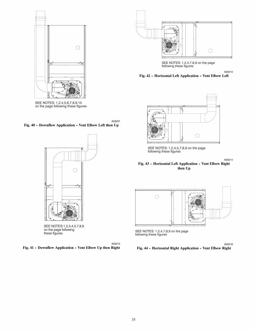
35
SEE NOTES: 1,2,4,5,6,7,8,9,10on the page following these figures
A03207
Fig. 40 -- Downflow Application -- Vent Elbow Left then Up
SEE NOTES:1,2,3,4,5,7,8,9on the page followingthese figures.
A03212
Fig. 41 -- Downflow Application -- Vent Elbow Up then Right
SEE NOTES: 1,2,4,7,8,9 on the pagefollowing these figures
A03213
Fig. 42 -- Horizontal Left Application -- Vent Elbow Left
SEE NOTES: 1,2,4,5,7,8,9 on the pagefollowing these figures
A03214
Fig. 43 -- Horizontal Left Application -- Vent Elbow Rightthen Up
SEE NOTES: 1,2,4,7,8,9 on the pagefollowing these figures
A03218
Fig. 44 -- Horizontal Right Application -- Vent Elbow Right

36
SEE NOTES: 1,2,4,5,7,8,9 on the pagefollowing these figures
A03215
Fig. 45 -- Horizontal Left Application -- Vent Elbow Up
SEE NOTES: 1,2,4,5,7,8,9 on the pagefollowing these figures
A03216
Fig. 46 -- Horizontal Left Application -- Vent Elbow Right
SEE NOTES: 1,2,4,5,7,8,9 on the pagefollowing these figures
A03219
Fig. 47 -- Horizontal Right Application -- Vent Elbow Leftthen Up
SEE NOTES: 1,2,4,5,7,8,9
A02068
Fig. 48 -- Horizontal Right Application--Vent Elbow Left
VENTING NOTES FOR FIG. 36 -- 481. For common vent, vent connector sizing and vent material: United States----use the NFGC.
2. Immediately increase to 5--in. (102 mm) or 6--in. (152 mm) vent connector outside furnace casing when 5--in. (127 mm) ventconnector is required, refer to Note 1 above.
3. Side outlet vent for upflow and downflow installations must use Type B vent immediately after exiting the furnace, except whenfactory--approved Downflow Vent Guard Kit is used in the downflow position. See Product Data Sheet for accessory listing.
4. Type--B vent where required, refer to Note 1 above.
5. A 4--in.(102 mm) single--wall (26 ga. min.) vent must be used inside furnace casing and when the factory--approved Downflow VentGuard Kit is used external to the furnace. See Product Data Sheet for accessory listing.
6. Accessory Downflow Vent Guard Kit required in downflow installations with lower vent configuration. See Product Data Sheet foraccessory listing.
7. Chimney Adapter Kit may be required for exterior masonry chimney applications. Refer to Chimney Adapter Kit for sizing andcomplete application details. See Product Data Sheet for accessory listing.
8. Secure vent connector to furnace elbow with (2) corrosion--resistant sheet metal screws, spaced approximately 180_ apart.
9. Secure all other single wall vent connector joints with (3) corrosion resistant screws spaced approximately 120_ apart. Secure Type--Bvent connectors per vent connector manufacturer’s recommendations.

37
Caution!! For the following applications, use the minimum vertical heights as specified below.For all other applications, follow exclusively the National Fuel Gas Code.
FURNACEORIENTATION
VENT ORIENTATION FURNACE INPUT(BTUH/HR)
MIN. VENTDIAMETERIN. (mm)*
MIN. VERTICAL VENTHEIGHTFT. (M)**
Downflow Vent elbow up then leftFig. 38 110,000 5 (127) 10 (3.0)
Downflow Vent elbow left, then upFig. 40
110,000132,000 5 (127) 12 (3.6)
Downflow Vent elbow up, then rightFig. 41 110,000 5 (127) 10 (3.0)
Horizontal Left Vent elbow right, then upFig. 43 132,000 5 (127) 7 (2.1)
Horizontal Left Vent Elbow upFig. 45 132,000 5 (127) 7 (2.1)
NOTE: All vent configurations must also meet National Fuel Gas Code venting requirements NFGC.*4---in. (102 mm) inside casing or vent guard**Including 4 in. (102 mm) vent section(s)
The horizontal portion of the venting system shall slope upwardsnot less than 1/4--in. per linear ft. (21 mm/m) from the furnace tothe vent and shall be rigidly supported every 5 ft. (1.5 M) or lesswith metal hangers or straps to ensure there is no movement afterinstallation.
Sidewall Venting
This furnace is not approved for direct sidewall horizontalventing.
Per section 12.4.3 of the NFPA 54/ANSI Z223.1, any listedmechanical venter may be used, when approved by the authorityhaving jurisdiction.
Select the listed mechanical venter to match the Btuh input of thefurnace being vented. Follow all manufacturer’s installationrequirements for venting and termination included with the listedmechanical venter.
START--UP, ADJUSTMENT, AND SAFETYCHECK
General
FIRE HAZARD
Failure to follow this warning could result in personal injury,death or property damage.
This furnace is equipped with manual reset limit switches inthe gas control area. The switches open and shut off power tothe gas valve, if a flame rollout or overheating conditionoccurs in the gas control area. DO NOT bypass the switches.Correct problem before resetting the switches.
! WARNING
1. Maintain 115--v wiring and ground. Improper polarity willresult in rapid flashing LED and no furnace operation.
2. Make thermostat wire connections at the 24--v terminalblock on the furnace control. Failure to make proper con-nections will result in improper operation. (See Fig. 25 --34.)
3. Gas supply pressure to the furnace must be greater than4.5--In. W.C. (0.16 psig ) but not exceed 14--In. W.C. (0.5psig).
4. Check all manual--reset switches for continuity.
5. Replace blower compartment door. Door must be in placeto operate furnace.
6. Setup switch descriptions The variable speed furnace con-trol has DIP switches to select thermostat staging, bloweroff delay timings, air flow selection and other operationalor service related functions. (See Fig. 26, 55 and Table52.)
CUT HAZARD
Failure to follow this caution may result in personal injury.
Sheet metal parts may have sharp edges or burrs. Use careand wear appropriate protective clothing, safety glasses andgloves when handling parts, and servicing furnaces.
CAUTION!
REGULATOR COVER SCREW
PLASTIC ADJUST SCREW
LOW STAGE GAS PRESSURE REGULATOR ADJUSTMENT
MANIFOLDPRESSURE TAP
INLETPRESSURE TAP
ON/OFF SWITCH
REGULATOR SPRING
HIGH STAGE GAS PRESSURE REGULATOR ADJUSTMENT
1/2˝ NPT OUTLET
1/2˝ NPT INLET
A04167
Fig. 49 -- Redundant Automatic Gas Control Valve
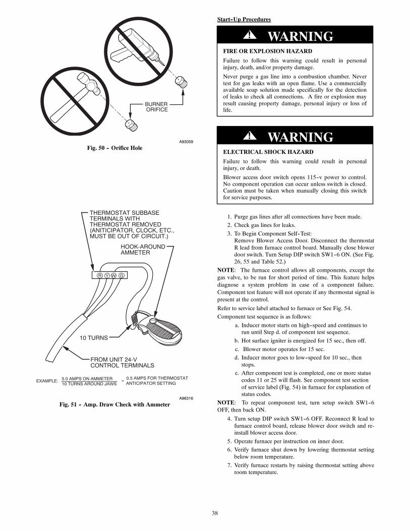
38
BURNER ORIFICE
A93059
Fig. 50 -- Orifice Hole
R Y W G
10 TURNS
THERMOSTAT SUBBASETERMINALS WITHTHERMOSTAT REMOVED(ANITICIPATOR, CLOCK, ETC.,MUST BE OUT OF CIRCUIT.)
HOOK-AROUNDAMMETER
EXAMPLE: 5.0 AMPS ON AMMETER10 TURNS AROUND JAWS
= 0.5 AMPS FOR THERMOSTAT ANTICIPATOR SETTING
FROM UNIT 24-VCONTROL TERMINALS
A96316
Fig. 51 -- Amp. Draw Check with Ammeter
Start--Up Procedures
FIRE OR EXPLOSION HAZARD
Failure to follow this warning could result in personalinjury, death, and/or property damage.
Never purge a gas line into a combustion chamber. Nevertest for gas leaks with an open flame. Use a commerciallyavailable soap solution made specifically for the detectionof leaks to check all connections. A fire or explosion mayresult causing property damage, personal injury or loss oflife.
! WARNING
ELECTRICAL SHOCK HAZARD
Failure to follow this warning could result in personalinjury, or death.
Blower access door switch opens 115--v power to control.No component operation can occur unless switch is closed.Caution must be taken when manually closing this switchfor service purposes.
! WARNING
1. Purge gas lines after all connections have been made.
2. Check gas lines for leaks.
3. To Begin Component Self--Test:Remove Blower Access Door. Disconnect the thermostatR lead from furnace control board. Manually close blowerdoor switch. Turn Setup DIP switch SW1--6 ON. (See Fig.26, 55 and Table 52.)
NOTE: The furnace control allows all components, except thegas valve, to be run for short period of time. This feature helpsdiagnose a system problem in case of a component failure.Component test feature will not operate if any thermostat signal ispresent at the control.
Refer to service label attached to furnace or See Fig. 54.
Component test sequence is as follows:
a. Inducer motor starts on high--speed and continues torun until Step d. of component test sequence.
b. Hot surface igniter is energized for 15 sec., then off.
c. Blower motor operates for 15 sec.
d. Inducer motor goes to low--speed for 10 sec., thenstops.
e. After component test is completed, one or more statuscodes 11 or 25 will flash. See component test sectionof service label (Fig. 54) in furnace for explanation ofstatus codes.
NOTE: To repeat component test, turn setup switch SW1--6OFF, then back ON.
4. Turn setup DIP switch SW1--6 OFF. Reconnect R lead tofurnace control board, release blower door switch and re-install blower access door.
5. Operate furnace per instruction on inner door.
6. Verify furnace shut down by lowering thermostat settingbelow room temperature.
7. Verify furnace restarts by raising thermostat setting aboveroom temperature.
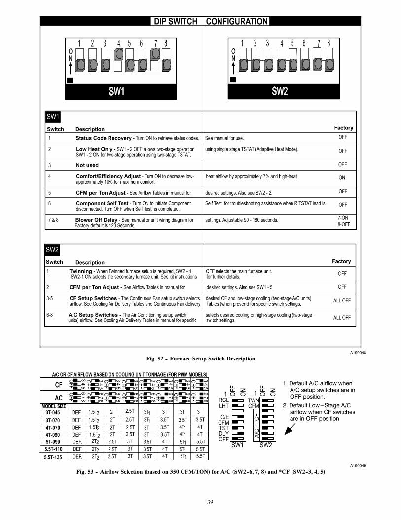
39
A190048
Fig. 52 -- Furnace Setup Switch Description
1. Default A/C airflow whenA/C setup switches are inOFF position.
2. Default Low---Stage A/Cairflow when CF switchesare in OFF position
A190049
Fig. 53 -- Airflow Selection (based on 350 CFM/TON) for A/C (SW2--6, 7, 8) and *CF (SW2--3, 4, 5)

40
A190047
Fig. 54 -- Service Label
Adjustments
FIRE HAZARD
Failure to follow this warning could result in personalinjury, death and/or property damage.
DO NOT bottom out gas valve regulator adjusting screw.This can result in unregulated manifold pressure and resultin excess overfire and heat exchanger failures.
! WARNING
FURNACE DAMAGE HAZARD
Failure to follow this caution may result in reduced furnacelife.
DO NOT redrill orifices. Improper drilling (burrs,out--of--round holes, etc.) can cause excessive burner noiseand misdirection of burner flames. This can result in flameimpingement of heat exchangers, causing failures. (See Fig.50.)
CAUTION!
Furnace gas input rate on rating plate is for installations ataltitudes up to 2000 Ft. (610 M). Furnace input rate must bewithin +/--2 percent of furnace rating plate input. For altitudesabove 5500 Ft. (1676 M), a field--supplied high altitude pressureswitch is required.
1. Determine the correct gas input rate.The input rating for altitudes above 2,000 ft. (610 M) mustbe reduced by 4 percent for each 1,000 ft. (305 M) abovesea level.For installations below 2000 Ft. (610 M), refer to the unitrating plate. For installations above 2000 Ft. (610 M),multiply the input on the rating plate by the de--rate multi-plier in Table 9 for the correct input rate.
2. Determine the correct orifice and manifold pressure adjust-ment. All models in all positions use Table 11 (22,000Btuh per burner.) See input listed on rating plate.
a. Obtain average yearly gas heat value (at installed alti-tude) from local gas supplier.
b. Obtain average yearly gas specific gravity from localgas supplier.
c. Find installation altitude in Table 11.
d. Find closest natural gas heat value and specific gravityin Table 11.
e. Follow heat value and specific gravity lines to point ofintersection to find orifice size and low--and high--heatmanifold pressure settings for proper operation.
f. Check and verify burner orifice size in furnace.NEVER ASSUME ORIFICE SIZE. ALWAYSCHECK AND VERIFY.
NOTE: If orifice hole appears damaged or it is suspected to havebeen redrilled, check orifice hole with a numbered drill bit ofcorrect size. Never redrill an orifice. A burr--free and squarelyaligned orifice hole is essential for proper flame characteristics.
g. Replace orifice with correct size, if required by Table11. Use only factory--supplied orifices. SeeEXAMPLE 1.
Table 9 – Altitude Derate Multiplier for U.S.A.
ALTITUDEFT. (M)
PERCENTOF DERATE
DERATE MULTIPLIERFACTOR*
0–2000(0---610) 0 1.00
2001–3000(610---914) 8–12 0.90
3001–4000(914---1219) 12–16 0.86
4001–5000(1219---1524) 16–20 0.82
5001–60001524---1829) 20–24 0.78
6001–7000(1829---2134) 24–28 0.74
7001–8000(2134---2438) 28–32 0.70
8001–9000(2438---2743) 32–36 0.66
9001–10,000(2743---3048) 36–40 0.62

41
EXAMPLE 1: 0–2000 ft. (0--610 M) altitudeFor 22,000 Btuh per burner application use Table 11.Heating value = 1000 Btuh/cu ft.Specific gravity = 0.62Therefore: Orifice No. 43*Manifold pressure: 3.7--In. W.C. for high--heat1.6--In. W.C. for low--heat* Furnace is shipped with No. 43 orifices. In this example allmain burner orifices are the correct size and donot need to be changed to obtain proper input rate.
3. Adjust manifold pressure to obtain low fire input rate. (SeeFig. 49.)
a. Turn gas valve ON/OFF switch to OFF.
b. Remove manifold pressure tap plug from gas valve.
c. Connect a water column manometer or similar deviceto manifold pressure tap.
d. Turn gas valve ON/OFF switch to ON.
e. Move setup SW1—2 on furnace control to ON posi-tion to lock furnace in low--heat operation. (See Table52 and Fig. 26.)
f. Manually close blower door switch.
g. Jumper R and W/W1 thermostat connections on con-trol to start furnace. (See Fig. 26.)
h. Remove regulator adjustment cap from low heat gasvalve pressure regulator (See Fig. 49.) and turn low--heat adjusting screw (3/16 or smaller flat--tippedscrewdriver) counterclockwise (out) to decrease inputrate or clockwise (in) to increase input rate.
NOTE: DO NOT set low--heat manifold pressure less than1.4--In. W.C. or more than 1.7--In. W.C. for natural gas. Ifmanifold pressure is outside this range, change main burnerorifices.
i. Install low--heat regulator adjustment cap.
j. Move setup switch SW1--2 to off position after com-pleting low--heat adjustment.
k. Leave manometer or similar device connected andproceed to Step 4.
4. Adjust manifold pressure to obtain high fire input rate.(See Fig. 49.)
a. Jumper R to W/W1 and W2 thermostat connections onfurnace control. This keeps furnace locked in high--heat operation.
b. Remove regulator adjustment cap from high--heat gasvalve pressure regulator (See Fig. 49) and turn highheat adjusting screw (3/16--in. or smaller flat--tippedscrewdriver) counterclockwise (out) to decrease inputrate or clockwise (in) to increase input rate.
NOTE: DO NOT set high--heat manifold pressure less than3.2--In. W.C. or more than 3.8 In. W.C. for natural gas. Ifmanifold pressure is outside this range, change main burnerorifices to obtain manifold pressure in this range.
c. When correct input is obtained, replace caps that con-ceal gas valve regulator adjustment screws. Mainburner flame should be clear blue, almost transparent.
d. Remove jumpers R to W/W1 and R to W2.
5. Verify natural gas input rate by clocking meter.
NOTE: Gas valve regulator adjustment caps must be in place forproper input to be clocked.
a. Turn off all other gas appliances and pilots served bythe meter.
b. Move setup switch SW1--2 to ON position. Thiskeeps furnace locked in low--heat operation.
c. Jumper R to W/W1.
d. Run furnace for 3 minutes in low--heat operation.
e. Measure time (in sec) for gas meter to complete 1revolution and note reading. The 2 or 5 cubic feet dialprovides a more accurate measurement of gas flow.
f. Refer to Table 10 for cubic ft. of gas per hr.
g. Multiply gas rate cu ft./hr by heating value (Btuh/cuft.) to obtain input. If clocked rate does not match re-quired input from Step 1, increase manifold pressure toincrease input or decrease manifold pressure to de-crease input. Repeat steps b through e until correctlow--heat input is achieved. Re--install low heat regu-lator seal cap on gas valve.
h. Move setup switch SW1--2 to OFF position and jump-er R to W/W1, and W2. This keeps furnace locked inhigh--heat operation. Repeat items d through g forhigh--heat operation.
6. Set Temperature Rise
NOTE: Blower access door must be installed when takingtemperature rise reading. Leaving blower access door off willresult in incorrect temperature measurements.
FURNACE DAMAGE HAZARD
Failure to follow this caution may result in shorten furnacelife.
Set air temperature rise within limits specified on the ratingplate to prevent reduced life of furnace components.Operation is within a few degrees of the mid--point of riserange when setup switch SW1--4 is OFF.
CAUTION!
UNIT DAMAGE HAZARD
Failure to follow this caution may result in overheating theheat exchangers or condensing flue gases in heat exchangerareas not designed for condensate.
Temperature rise must be within limits specified on unitrating plate. Operation is within a few degrees of midpointof rise range when setup switch SW1--4 is OFF.
CAUTION!
When setup switch SW1--4 is ON, operation will be near the highend of the rise range for improved comfort.
Furnace must operate within ranges of temperature rise specifiedon the furnace rating plate. Determine air temperature rise asfollows:
a. Place thermometers in return and supply ducts as nearfurnace as possible. Be sure thermometers do not seeheat exchanger so that radiant heat does not affectreadings. This practice is particularly important withstraight--run ducts.
b. When thermometer readings stabilize, subtract return--air temperature from supply--air temperature to determ-ine air temperature rise.
NOTE: Temperature rise can be determined for low--heatoperation by placing setup switch SW1--2 on furnace control inON position. For high--heat operation, place setup switch SW1--2in OFF position and jumper R--W2 on furnace control. DO NOTforget to return setup switch to OFF position and remove R--W2jumper upon completion of testing.
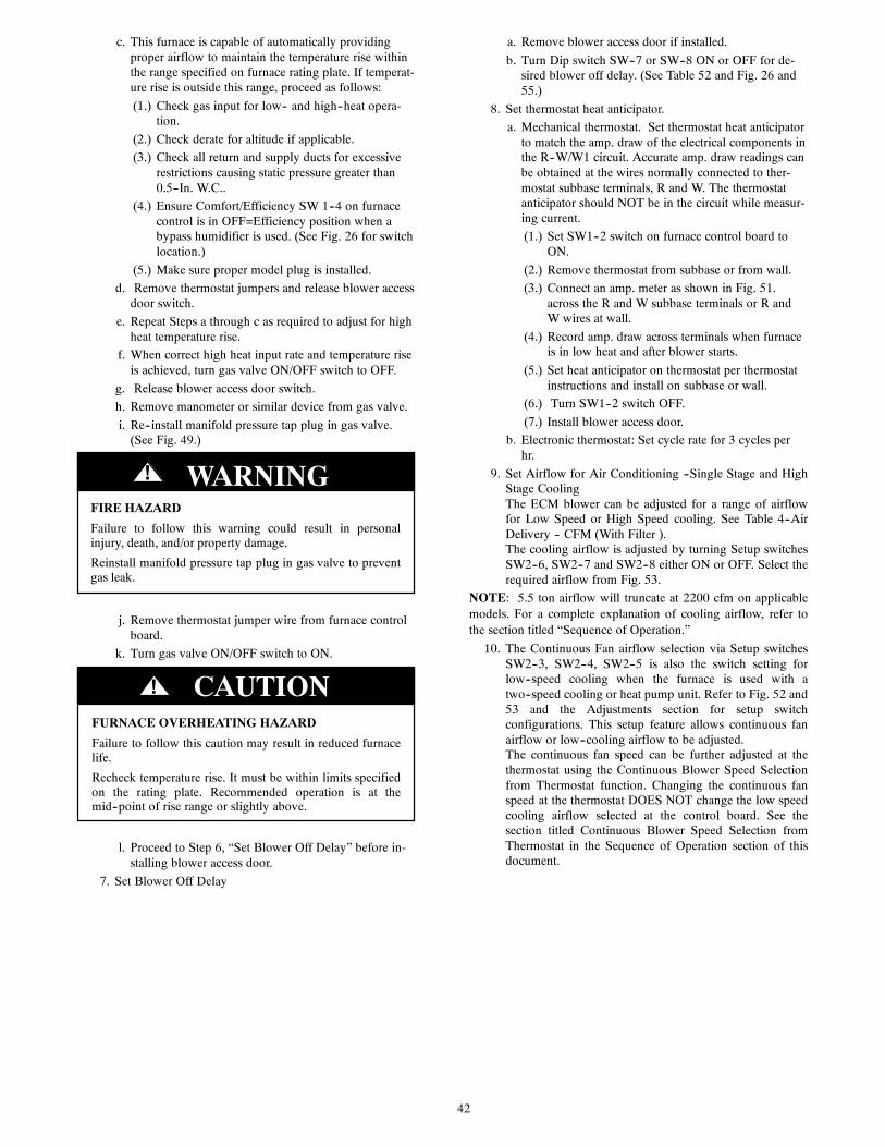
42
c. This furnace is capable of automatically providingproper airflow to maintain the temperature rise withinthe range specified on furnace rating plate. If temperat-ure rise is outside this range, proceed as follows:
(1.) Check gas input for low-- and high--heat opera-tion.
(2.) Check derate for altitude if applicable.
(3.) Check all return and supply ducts for excessiverestrictions causing static pressure greater than0.5--In. W.C..
(4.) Ensure Comfort/Efficiency SW 1--4 on furnacecontrol is in OFF=Efficiency position when abypass humidifier is used. (See Fig. 26 for switchlocation.)
(5.) Make sure proper model plug is installed.
d. Remove thermostat jumpers and release blower accessdoor switch.
e. Repeat Steps a through c as required to adjust for highheat temperature rise.
f. When correct high heat input rate and temperature riseis achieved, turn gas valve ON/OFF switch to OFF.
g. Release blower access door switch.
h. Remove manometer or similar device from gas valve.
i. Re--install manifold pressure tap plug in gas valve.(See Fig. 49.)
FIRE HAZARD
Failure to follow this warning could result in personalinjury, death, and/or property damage.
Reinstall manifold pressure tap plug in gas valve to preventgas leak.
! WARNING
j. Remove thermostat jumper wire from furnace controlboard.
k. Turn gas valve ON/OFF switch to ON.
FURNACE OVERHEATING HAZARD
Failure to follow this caution may result in reduced furnacelife.
Recheck temperature rise. It must be within limits specifiedon the rating plate. Recommended operation is at themid--point of rise range or slightly above.
CAUTION!
l. Proceed to Step 6, “Set Blower Off Delay” before in-stalling blower access door.
7. Set Blower Off Delay
a. Remove blower access door if installed.
b. Turn Dip switch SW--7 or SW--8 ON or OFF for de-sired blower off delay. (See Table 52 and Fig. 26 and55.)
8. Set thermostat heat anticipator.
a. Mechanical thermostat. Set thermostat heat anticipatorto match the amp. draw of the electrical components inthe R--W/W1 circuit. Accurate amp. draw readings canbe obtained at the wires normally connected to ther-mostat subbase terminals, R and W. The thermostatanticipator should NOT be in the circuit while measur-ing current.
(1.) Set SW1--2 switch on furnace control board toON.
(2.) Remove thermostat from subbase or from wall.
(3.) Connect an amp. meter as shown in Fig. 51.across the R and W subbase terminals or R andW wires at wall.
(4.) Record amp. draw across terminals when furnaceis in low heat and after blower starts.
(5.) Set heat anticipator on thermostat per thermostatinstructions and install on subbase or wall.
(6.) Turn SW1--2 switch OFF.
(7.) Install blower access door.
b. Electronic thermostat: Set cycle rate for 3 cycles perhr.
9. Set Airflow for Air Conditioning --Single Stage and HighStage CoolingThe ECM blower can be adjusted for a range of airflowfor Low Speed or High Speed cooling. See Table 4--AirDelivery -- CFM (With Filter ).The cooling airflow is adjusted by turning Setup switchesSW2--6, SW2--7 and SW2--8 either ON or OFF. Select therequired airflow from Fig. 53.
NOTE: 5.5 ton airflow will truncate at 2200 cfm on applicablemodels. For a complete explanation of cooling airflow, refer tothe section titled “Sequence of Operation.”
10. The Continuous Fan airflow selection via Setup switchesSW2--3, SW2--4, SW2--5 is also the switch setting forlow--speed cooling when the furnace is used with atwo--speed cooling or heat pump unit. Refer to Fig. 52 and53 and the Adjustments section for setup switchconfigurations. This setup feature allows continuous fanairflow or low--cooling airflow to be adjusted.The continuous fan speed can be further adjusted at thethermostat using the Continuous Blower Speed Selectionfrom Thermostat function. Changing the continuous fanspeed at the thermostat DOES NOT change the low speedcooling airflow selected at the control board. See thesection titled Continuous Blower Speed Selection fromThermostat in the Sequence of Operation section of thisdocument.

43
A190046
Fig. 55 -- Wiring Diagram

44
Table 10 – Gas Rate (CU ft./hr)
SECONDS GFOR 1 REVOLUTION
SIZE OF TEST DIAL SECONDSFOR 1 REVOLUTION
SIZE OF TEST DIAL1 Cu Ft. 2 Cu Ft. 5 Cu Ft. 1 Cu Ft. 2 Cu Ft. 5 Cu Ft.
10 360 720 1800 50 72 144 36011 327 655 1636 51 71 141 35512 300 600 1500 52 69 138 34613 277 555 1385 53 68 136 34014 257 514 1286 54 67 133 33315 240 480 1200 55 65 131 32716 225 450 1125 56 64 129 32117 212 424 1059 57 63 126 31618 200 400 1000 58 62 124 31019 189 379 947 59 61 122 30520 180 360 900 60 60 120 30021 171 343 857 62 58 116 29022 164 327 818 64 56 112 28123 157 313 783 66 54 109 27324 150 300 750 68 53 106 26525 144 288 720 70 51 103 25726 138 277 692 72 50 100 25027 133 267 667 74 48 97 24328 129 257 643 76 47 95 23729 124 248 621 78 46 92 23130 120 240 600 80 45 90 22531 116 232 581 82 44 88 22032 113 225 563 84 43 86 21433 109 218 545 86 42 84 20934 106 212 529 88 41 82 20535 103 206 514 90 40 80 20036 100 200 500 92 39 78 19637 97 195 486 94 38 76 19238 95 189 474 96 38 75 18839 92 185 462 98 37 74 18440 90 180 450 100 36 72 18041 88 176 439 102 35 71 17842 86 172 429 104 35 69 17343 84 167 419 106 34 68 17044 82 164 409 108 33 67 16745 80 160 400 110 33 65 16446 78 157 391 112 32 64 16147 76 153 383 116 31 62 15548 75 150 375 120 30 60 15049 73 147 367
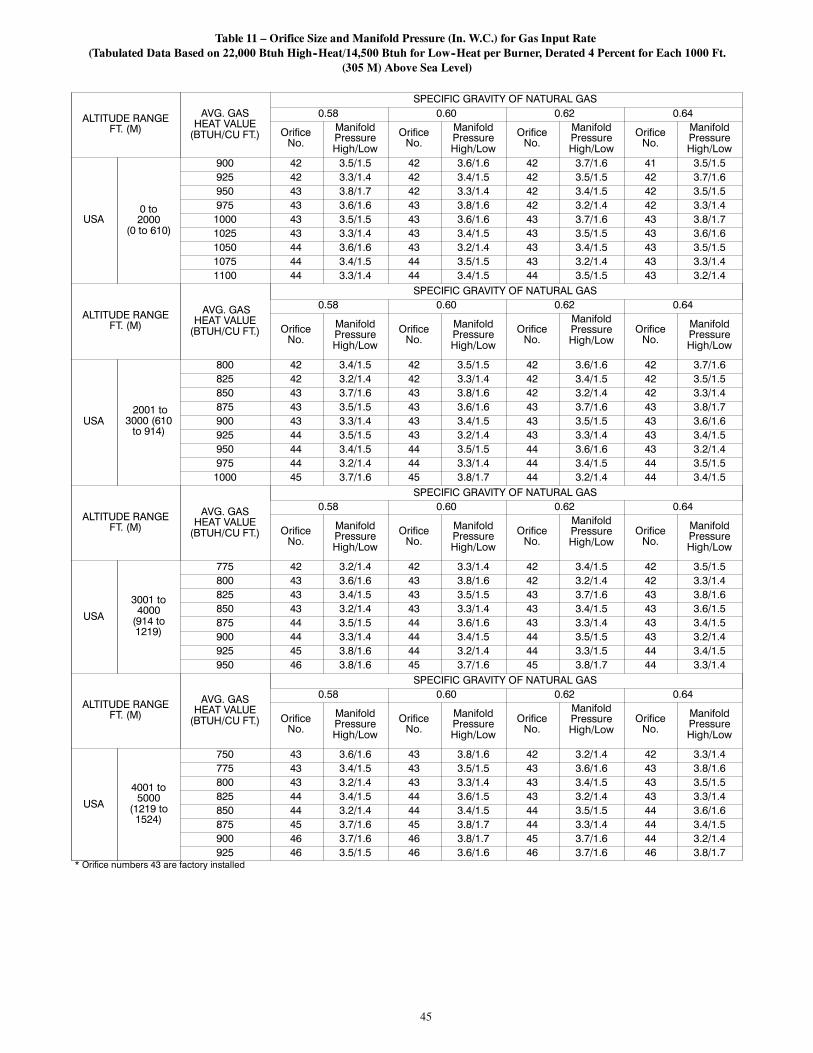
45
Table 11 – Orifice Size and Manifold Pressure (In. W.C.) for Gas Input Rate(Tabulated Data Based on 22,000 Btuh High--Heat/14,500 Btuh for Low--Heat per Burner, Derated 4 Percent for Each 1000 Ft.
(305 M) Above Sea Level)
ALTITUDE RANGEFT. (M)
AVG. GASHEAT VALUE(BTUH/CU FT.)
SPECIFIC GRAVITY OF NATURAL GAS0.58 0.60 0.62 0.64
OrificeNo.
ManifoldPressureHigh/Low
OrificeNo.
ManifoldPressureHigh/Low
OrificeNo.
ManifoldPressureHigh/Low
OrificeNo.
ManifoldPressureHigh/Low
USA0 to2000
(0 to 610)
900 42 3.5/1.5 42 3.6/1.6 42 3.7/1.6 41 3.5/1.5925 42 3.3/1.4 42 3.4/1.5 42 3.5/1.5 42 3.7/1.6950 43 3.8/1.7 42 3.3/1.4 42 3.4/1.5 42 3.5/1.5975 43 3.6/1.6 43 3.8/1.6 42 3.2/1.4 42 3.3/1.41000 43 3.5/1.5 43 3.6/1.6 43 3.7/1.6 43 3.8/1.71025 43 3.3/1.4 43 3.4/1.5 43 3.5/1.5 43 3.6/1.61050 44 3.6/1.6 43 3.2/1.4 43 3.4/1.5 43 3.5/1.51075 44 3.4/1.5 44 3.5/1.5 43 3.2/1.4 43 3.3/1.41100 44 3.3/1.4 44 3.4/1.5 44 3.5/1.5 43 3.2/1.4
ALTITUDE RANGEFT. (M)
AVG. GASHEAT VALUE(BTUH/CU FT.)
SPECIFIC GRAVITY OF NATURAL GAS0.58 0.60 0.62 0.64
OrificeNo.
ManifoldPressureHigh/Low
OrificeNo.
ManifoldPressureHigh/Low
OrificeNo.
ManifoldPressureHigh/Low
OrificeNo.
ManifoldPressureHigh/Low
USA2001 to3000 (610to 914)
800 42 3.4/1.5 42 3.5/1.5 42 3.6/1.6 42 3.7/1.6825 42 3.2/1.4 42 3.3/1.4 42 3.4/1.5 42 3.5/1.5850 43 3.7/1.6 43 3.8/1.6 42 3.2/1.4 42 3.3/1.4875 43 3.5/1.5 43 3.6/1.6 43 3.7/1.6 43 3.8/1.7900 43 3.3/1.4 43 3.4/1.5 43 3.5/1.5 43 3.6/1.6925 44 3.5/1.5 43 3.2/1.4 43 3.3/1.4 43 3.4/1.5950 44 3.4/1.5 44 3.5/1.5 44 3.6/1.6 43 3.2/1.4975 44 3.2/1.4 44 3.3/1.4 44 3.4/1.5 44 3.5/1.51000 45 3.7/1.6 45 3.8/1.7 44 3.2/1.4 44 3.4/1.5
ALTITUDE RANGEFT. (M)
AVG. GASHEAT VALUE(BTUH/CU FT.)
SPECIFIC GRAVITY OF NATURAL GAS0.58 0.60 0.62 0.64
OrificeNo.
ManifoldPressureHigh/Low
OrificeNo.
ManifoldPressureHigh/Low
OrificeNo.
ManifoldPressureHigh/Low
OrificeNo.
ManifoldPressureHigh/Low
USA3001 to4000(914 to1219)
775 42 3.2/1.4 42 3.3/1.4 42 3.4/1.5 42 3.5/1.5800 43 3.6/1.6 43 3.8/1.6 42 3.2/1.4 42 3.3/1.4825 43 3.4/1.5 43 3.5/1.5 43 3.7/1.6 43 3.8/1.6850 43 3.2/1.4 43 3.3/1.4 43 3.4/1.5 43 3.6/1.5875 44 3.5/1.5 44 3.6/1.6 43 3.3/1.4 43 3.4/1.5900 44 3.3/1.4 44 3.4/1.5 44 3.5/1.5 43 3.2/1.4925 45 3.8/1.6 44 3.2/1.4 44 3.3/1.5 44 3.4/1.5950 46 3.8/1.6 45 3.7/1.6 45 3.8/1.7 44 3.3/1.4
ALTITUDE RANGEFT. (M)
AVG. GASHEAT VALUE(BTUH/CU FT.)
SPECIFIC GRAVITY OF NATURAL GAS0.58 0.60 0.62 0.64
OrificeNo.
ManifoldPressureHigh/Low
OrificeNo.
ManifoldPressureHigh/Low
OrificeNo.
ManifoldPressureHigh/Low
OrificeNo.
ManifoldPressureHigh/Low
USA4001 to5000(1219 to1524)
750 43 3.6/1.6 43 3.8/1.6 42 3.2/1.4 42 3.3/1.4775 43 3.4/1.5 43 3.5/1.5 43 3.6/1.6 43 3.8/1.6800 43 3.2/1.4 43 3.3/1.4 43 3.4/1.5 43 3.5/1.5825 44 3.4/1.5 44 3.6/1.5 43 3.2/1.4 43 3.3/1.4850 44 3.2/1.4 44 3.4/1.5 44 3.5/1.5 44 3.6/1.6875 45 3.7/1.6 45 3.8/1.7 44 3.3/1.4 44 3.4/1.5900 46 3.7/1.6 46 3.8/1.7 45 3.7/1.6 44 3.2/1.4925 46 3.5/1.5 46 3.6/1.6 46 3.7/1.6 46 3.8/1.7
* Orifice numbers 43 are factory installed

46
Table 11 -- Orifice Size and Manifold Pressure (In. W.C.) for Gas Input Rate (Con’t.)(Tabulated Data Based on 22,000 Btuh High--Heat/14,500 Btuh for Low--Heat per Burner, Derated 4 Percent for Each 1000 Ft.
Above Sea Level)
ALTITUDERANGEFT. (M)
AVG. GASHEAT VALUEAT ALTITUDE(BTUH/CU FT.)
SPECIFIC GRAVITY OF NATURAL GAS0.58 0.60 0.62 0.64
OrificeNo.
ManifoldPressureHigh/Low
OrificeNo.
ManifoldPressureHigh/Low
OrificeNo.
ManifoldPressureHigh/Low
OrificeNo.
ManifoldPressureHigh/Low
USA
5001 to6000(1524to1829)
725 43 3.4/1.5 43 3.5/1.5 43 3.6/1.6 43 3.7/1.6750 43 3.2/1.4 43 3.3/1.4 43 3.4/1.5 43 3.5/1.5775 44 3.4/1.5 44 3.5/1.5 43 3.2/1.4 43 3.3/1.4800 44 3.2/1.4 44 3.3/1.4 44 3.4/1.5 44 3.5/1.5825 46 3.8/1.7 45 3.8/1.6 44 3.2/1.4 44 3.3/1.4850 46 3.6/1.6 46 3.7/1.6 46 3.8/1.7 45 3.8/1.6875 47 3.8/1.7 46 3.5/1.5 46 3.6/1.6 46 3.7/1.6900 47 3.6/1.6 47 3.8/1.6 46 3.4/1.5 46 3.5/1.5
ALTITUDERANGEFT. (M)
AVG. GASHEAT VALUEAT ALTITUDE(BTUH/CU FT.)
SPECIFIC GRAVITY OF NATURAL GAS0.58 0.60 0.62 0.64
OrificeNo.
ManifoldPressureHigh/Low
OrificeNo.
ManifoldPressureHigh/Low
OrificeNo.
ManifoldPressureHigh/Low
OrificeNo.
ManifoldPressureHigh/Low
USA
6001 to7000(1829to2134)
675 43 3.4/1.5 43 3.5/1.5 43 3.6/1.6 43 3.7/1.6700 44 3.6/1.6 43 3.3/1.4 43 3.4/1.5 43 3.5/1.5725 44 3.4/1.5 44 3.5/1.5 44 3.6/1.6 43 3.2/1.4750 45 3.8/1.7 44 3.3/1.4 44 3.4/1.5 44 3.5/1.5775 46 3.7/1.6 45 3.7/1.6 45 3.8/1.7 44 3.2/1.4800 46 3.5/1.5 46 3.6/1.6 46 3.8/1.6 45 3.7/1.6825 47 3.7/1.6 46 3.4/1.5 46 3.5/1.5 46 3.6/1.6850 47 3.5/1.5 47 3.6/1.6 47 3.8/1.6 46 3.4/1.5
ALTITUDERANGEFT. (M)
AVG. GASHEAT VALUEAT ALTITUDE(BTUH/CU FT.)
SPECIFIC GRAVITY OF NATURAL GAS0.58 0.60 0.62 0.64
OrificeNo.
ManifoldPressureHigh/Low
OrificeNo.
ManifoldPressureHigh/Low
OrificeNo.
ManifoldPressureHigh/Low
OrificeNo.
ManifoldPressureHigh/Low
USA
7001 to8000(2134to2438)
650 44 3.6/1.6 43 3.2/1.4 43 3.4/1.5 43 3.5/1.5675 44 3.3/1.5 44 3.5/1.5 44 3.6/1.6 43 3.2/1.4700 45 3.8/1.6 44 3.2/1.4 44 3.3/1.4 44 3.4/1.5725 46 3.7/1.6 46 3.8/1.7 45 3.7/1.6 44 3.2/1.4750 46 3.4/1.5 46 3.6/1.5 46 3.7/1.6 46 3.8/1.6775 47 3.6/1.6 47 3.8/1.6 46 3.4/1.5 46 3.6/1.5800 47 3.4/1.5 47 3.5/1.5 47 3.7/1.6 47 3.8/1.6825 48 3.7/1.6 48 3.8/1.6 47 3.4/1.5 47 3.6/1.5
ALTITUDERANGEFT. (M)
AVG. GASHEAT VALUEAT ALTITUDE(BTUH/CU FT.)
SPECIFIC GRAVITY OF NATURAL GAS0.58 0.60 0.62 0.64
OrificeNo.
ManifoldPressureHigh/Low
OrificeNo.
ManifoldPressureHigh/Low
OrificeNo.
ManifoldPressureHigh/Low
OrificeNo.
ManifoldPressureHigh/Low
USA
8001 to9000(2438to2743)
625 44 3.3/1.5 44 3.5/1.5 44 3.6/1.6 43 3.2/1.4650 45 3.7/1.6 44 3.2/1.4 44 3.3/1.4 44 3.4/1.5675 46 3.6/1.6 46 3.8/1.6 45 3.7/1.6 45 3.8/1.7700 47 3.8/1.7 46 3.5/1.5 46 3.6/1.6 46 3.7/1.6725 47 3.6/1.6 47 3.7/1.6 47 3.8/1.7 46 3.5/1.5750 48 3.8/1.7 47 3.5/1.5 47 3.6/1.6 47 3.7/1.6775 48 3.6/1.5 48 3.7/1.6 48 3.8/1.7 47 3.5/1.5
USA
9001 to10,0002743 to3048)
600 45 3.7/1.6 45 3.8/1.7 44 3.3/1.4 44 3.4/1.5625 46 3.6/1.6 46 3.7/1.6 46 3.8/1.7 45 3.8/1.6650 47 3.8/1.6 46 3.4/1.5 46 3.6/1.5 46 3.7/1.6675 47 3.5/1.5 47 3.6/1.6 47 3.7/1.6 46 3.4/1.5700 48 3.7/1.6 48 3.8/1.7 47 3.5/1.5 47 3.6/1.6725 48 3.5/1.5 48 3.6/1.6 48 3.7/1.6 48 3.8/1.7
* Orifice numbers 43 are factory installed

47
Check Safety Controls
The flame sensor, gas valve, and pressure switch were all checkedin the Start--up procedure section as part of normal operation.
1. Check Main Limit SwitchThis control shuts off combustion system and energizesair--circulating blower motor, if furnace overheats. By us-ing this method to check limit control, it can be establishedthat limit is functioning properly and will operate if thereis a restricted return--air supply or motor failure. If limitcontrol does not function during this test, cause must bedetermined and corrected.
a. Run furnace for at least 5 minutes.
b. Gradually block off return air with a piece of card-board or sheet metal until the limit trips.
c. Unblock return air to permit normal circulation.
d. Burners will re--light when furnace cools down.
2. Check draft safeguard switch. The purpose of this controlis to cause the safe shutdown of the furnace during certainblocked vent conditions.
a. Verify vent pipe is cool to the touch.
b. Disconnect power to furnace and remove vent connec-tor from furnace vent elbow.
c. Restore power to furnace and set room thermostatabove room temperature.
d. After normal start--up, allow furnace to operate for 2minutes, then block vent elbow in furnace 80 percentof vent area with a piece of flat sheet metal.
e. Furnace should cycle off within 2 minutes. If gas doesnot shut off within 2 minutes, determine reason draftsafeguard switch did not function properly and correctcondition.
f. Remove blockage from furnace vent elbow.
g. Switch will auto--reset when it cools.
h. Re--install vent connector.
NOTE: Should switch remain open longer than 3 minutes,furnace control board will lockout the furnace for 3 hours. Toreset furnace control board, turn thermostat below roomtemperature or from HEAT to OFF and turn 115--v power OFF,then back ON.
3. Check Pressure Switch(es)This control proves operation of the draft inducer blower.
a. Turn off 115--v power to furnace.
b. Disconnect inducer motor lead wires from wire har-ness.
c. Turn on 115--v power to furnace.
d. Set thermostat to “call for heat” and wait 1 minute.When pressure switch is functioning properly, hot sur-face igniter should NOT glow and control diagnosticlight flashes a status code 32 . If hot surface igniterglows when inducer motor is disconnected, shut downfurnace immediately.
e. Determine reason pressure switch did not functionproperly and correct condition.
f. Turn off 115--v power to furnace.
g. Reconnect inducer motor wires, replace outer door,and turn on 115--v power.
h. Blower will run for 90 seconds before beginning thecall for heat again.
i. Furnace should ignite normally.
Checklist
1. Put away tools and instruments. Clean up debris.
2. Verify that switches SW1--1 and SW1--6 are OFF and oth-er setup switches are set as desired. Verify that switchesSW1--7 and SW1--8 for the blower OFF DELAY are set asdesired per Table 12.
3. Verify that blower and burner access doors are properly in-stalled.
4. Cycle test furnace with room thermostat.
5. Check operation of accessories per manufacturer’s instruc-tions.
6. Review User’s Guide with owner.
7. Attach literature packet to furnace.
Table 12 – Blower Off Delay Setup Switch
DESIRED HEATING MODEBLOWER OFF DELAY (SEC.)
SETUP SWITCH(SW---7 AND ---8)POSITION
SW1---7 SW1---890 OFF OFF120 ON OFF150 OFF ON180 ON ON
SERVICE AND MAINTENANCEPROCEDURES
Untrained personnel can perform basic maintenance functionssuch as cleaning and replacing air filters. All other operationsmust be performed by trained service personnel. A qualifiedservice person should inspect the furnace once a year.
FIRE, INJURY OR DEATH HAZARD
Failure to follow this warning could result in personalinjury, death and/or property damage.
The ability to properly perform maintenance on thisequipment requires certain knowledge, mechanical skills,tools, and equipment. If you do not possess these, do notattempt to perform any maintenance on this equipmentother than those procedures recommended in the User’sManual.
! WARNING
ENVIRONMENTAL HAZARD
Failure to follow this caution may result in environmentalpollution.
Remove and recycle all components or materials (i.e. oil,refrigerant, control board, etc.) before unit final disposal.
CAUTION!
ELECTRICAL SHOCK, FIRE OR EXPLOSIONHAZARD
Failure to follow this warning could result in personalinjury or death, or property damage.
Before installing, modifying, or servicing system, mainelectrical disconnect switch must be in the OFF position andinstall a lockout tag. There may be more than onedisconnect switch. Lock out and tag switch with a suitablewarning label. Verify proper operation after servicing.
! WARNING

48
ELECTRICAL OPERATION HAZARD
Failure to follow this caution may result in improperfurnace operation or failure of furnace.
Label all wires prior to disconnection when servicingcontrols. Wiring errors can cause improper and dangerousoperation.
CAUTION!
General
These instructions are written as if the furnace is installed in anupflow application. An upflow furnace application is where theblower is located below the combustion and controls section ofthe furnace, and conditioned air is discharged upward. Since thisfurnace can be installed in any of the 4 positions shown in Fig. 4,you must revise your orientation to component locationaccordingly.
Electrical Controls and Wiring
ELECTRICAL SHOCK HAZARD
Failure to follow this warning could result in personal injuryor death.
There may be more than one electrical supply to the furnace.Check accessories and cooling unit for additional electricalsupplies that must be shut off during furnace servicing. Lockout and tag switch with a suitable warning label.
! WARNING
The electrical ground and polarity for 115--v wiring must beproperly maintained. Refer to Fig. 25 for field wiring informationand to Fig. 55 for furnace wiring information.
NOTE: If the polarity is not correct, the STATUS LED on thecontrol will flash rapidly and prevent the furnace from heating.The control system also requires an earth ground for properoperation of the control and flame--sensing electrode.
The 24--v circuit contains an automotive--type, 3--amp. fuselocated on the control. (See Fig. 26.) Any shorts of the 24--vwiring during installation, service, or maintenance will cause thisfuse to blow. If fuse replacement is required, use ONLY a 3--amp.fuse. The control LED will display status code 24 when fuseneeds to be replaced.
Proper instrumentation is required to service electrical controls.The control in this furnace is equipped with a Status Code LED(Light--Emitting Diode) to aid in installation, servicing, andtroubleshooting. Status codes can be viewed at the sight glass inblower access door. The amber furnace control LED is either ONcontinuously, rapid flashing, or a code composed of 2 digits. Thefirst digit is the number of short flashes, the second digit is thenumber of long flashes.
For an explanation of status codes, refer to service label locatedon blower access door or Fig. 54.
See Fig. 59, a brief Troubleshooting Guide.
For 2--Stage Variable Speed ECM Controls the stored statuscodes will NOT be erased from the control memory, when 115--or 24--v power is interrupted. The control will store up to the last7 Status Codes in order of occurrence.
1. To retrieve status codes, proceed with the following:
NOTE: NO thermostat signal may be present at control, and allblower--OFF delays must be completed.
a. Leave 115--v power to furnace turned on.
b. Remove outer access door.
c. Look into blower access door sight glass for currentLED status.
d. Remove blower access door.
NOTE: The Status Codes cannot be retrieved by disconnectingthe limit switch or draft safeguard switch. To retrieve StatusCodes, follow the procedure below.
2. Turn Setup Switch, SW1--1 “ON.”
3. Manually close blower access door switch.
4. Control will flash up to 7 Status Codes.
5. The last Status Code, or 8th Code, will be Code 11.
6. Turn SW1--1 “OFF.”
7. A continuously--lit Amber LED will appear and indicatesproper operation.
8. Release blower access door switch, install blower accessdoor and replace outer door or refer to the SERVICE labelon the front of the blower access door for more informa-tion.
Component Self--Test
Component Test can ONLY be initiated by performing thefollowing:
1. Remove outer access door.
2. Remove blower access door.
3. Remove the wire from the “R” terminal of the controlboard.
4. Turn Setup Switch, SW--1--6 “ON.”
5. Manually close blower access door switch.
Blower access door switch opens 115--v power to control. Nocomponent operation can occur unless switch is closed. Cautionmust be taken when manually closing this switch for servicepurposes.
ELECTRICAL SHOCK HAZARD
Failure to follow this warning could result in personal injury,or death.
Blower access door switch opens 115--v power to furnacecontrol. No component operation can occur unless switch isclosed. Exercise caution to avoid electrical shock fromexposed electrical components when manually closing thisswitch for service purposes.
! WARNING
6. Component Test sequence will function as follows:
a. Inducer motor starts on high--speed and continues torun until Step (d.) of component test sequence.
b. Hot surface igniter is energized for 15 sec, then deen-ergized.
c. Blower operates for 10 sec, then turns off.
d. Inducer motor goes to low--speed for 10 seconds, thenturns off.
e. After component test is completed, one or more statuscodes 11 or 25 will flash. See component test sectionof service label for explanation of status codes.
NOTE: To repeat component test, turn setup switch SW1--6 OFFthen back ON.
f. Turn setup switch SW1--6 OFF.
7. RELEASE BLOWER ACCESS DOOR SWITCH, reat-tach wire to “R” terminal on furnace control board, replaceblower access door, and replace outer access door.

49
CARE AND MAINTENANCE
FIRE OR EXPLOSION HAZARD
Failure to follow this warning could result in personalinjury, death and/or property damage.
Never store anything on, near, or in contact with thefurnace, such as:
1. Spray or aerosol cans, rags, brooms, dust mops,vacuum cleaners, or other cleaning tools.
2. Soap powders, bleaches, waxes or other cleaningcompounds, plastic or plastic containers, gasoline,kerosene, cigarette lighter fluid, dry cleaning fluids,or other volatile fluids.
3. Paint thinners and other painting compounds, paperbags, or other paper products. Exposure to thesematerials could lead to corrosion of the heatexchangers.
! WARNING
For continuing high performance and to minimize possiblefurnace failure, periodic maintenance must be performed on thisfurnace. Consult your local dealer about proper frequency ofmaintenance and the availability of a maintenance contract.
ELECTRICAL SHOCK AND FIRE HAZARD
Failure to follow this warning could result in personal injury,death, and/or property damage.
Turn off the gas and electrical supplies to the furnace andinstall lockout tag before performing any maintenance orservice. Follow the operating instructions on the labelattached to the furnace.
! WARNING
CARBON MONOXIDE POISONING AND FIREHAZARD
Failure to follow this warning could result in personalinjury, death and/or property damage.
Never operate furnace without a filter or with filter accessdoor removed.
! WARNING
CUT HAZARD
Failure to follow this caution may result in personal injury.
Sheet metal parts may have sharp edges or burrs. Use careand wear appropriate protective clothing, safety glasses andgloves when handling parts, and servicing furnaces.
CAUTION!
The minimum maintenance on this furnace is as follows:
1. Check and clean air filter each month or more frequently ifrequired. Replace if torn.
2. Check blower motor and wheel for cleanliness each heat-ing and cooling season. Clean as necessary.
3. Check electrical connections for tightness and controls forproper operation each heating season. Service as neces-sary.
4. Inspect burner compartment before each heating seasonfor rust, corrosion, soot or excessive dust. If necessary,
have furnace and burner serviced by a qualified serviceagency.
5. Inspect the vent pipe/vent system before each heating sea-son for rust, corrosion, water leakage, sagging pipes orbroken fittings. Have vent pipes/vent system serviced by aqualified service agency.
6. Inspect any accessories attached to the furnace such as ahumidifier or electronic air cleaner. Perform any service ormaintenance to the accessories as recommended in the ac-cessory instructions.
Cleaning and/or Replacing Air Filter
The air filter arrangement will vary depending on the application.
NOTE: If the filter has an airflow direction arrow, the arrowmust point towards the blower.
CUT HAZARD
Failure to follow this caution may result in personal injury.
Sheet metal parts may have sharp edges or burrs. Use careand wear appropriate protective clothing, safety glasses andgloves when handling parts, and servicing furnaces.
CAUTION!
Media cabinet filter procedures:
1. Turn off electrical supply to furnace before removing filteraccess door.
2. Remove filter cabinet door.
3. Slide filter out of cabinet.
4. If equipped with permanent, washable 3/4--in. (19 mm)filter, clean filter by spraying cold tap water through filterin opposite direction of airflow. Rinse filter and let dry.Oiling or coating of the filter is not recommended. See Ta-ble 13 for size information.
5. If equipped with factory--specified disposable media filter,replace only with media filter having the same part num-ber and size. For expandable replacement media, refer tothe instructions included with the replacement media.
6. Slide filter into cabinet.
7. Replace filter cabinet door.
8. Turn on electrical supply to furnace.
Blower Motor and Wheel
ELECTRICAL SHOCK HAZARD
Failure to follow this warning could result in personalinjury or death.
Blower access door switch opens 115--v power to control.No component operation can occur unless switch is closed.Caution must be taken when manually closing this switchfor service purposes.
! WARNING
NOTE: The blower wheel should not be dropped or bent asbalance will be affected.
The following steps should be performed by a qualifiedservice agency.To ensure long life and high efficiency, clean accumulated dirtand grease from blower wheel and motor annually.
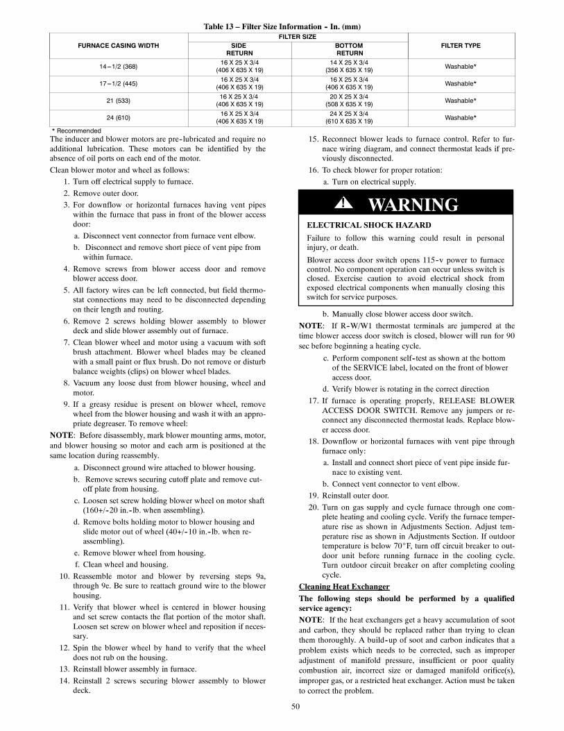
50
Table 13 – Filter Size Information -- In. (mm)
FURNACE CASING WIDTHFILTER SIZE
FILTER TYPESIDERETURN
BOTTOMRETURN
14---1/2 (368) 16 X 25 X 3/4(406 X 635 X 19)
14 X 25 X 3/4(356 X 635 X 19) Washable*
17---1/2 (445) 16 X 25 X 3/4(406 X 635 X 19)
16 X 25 X 3/4(406 X 635 X 19) Washable*
21 (533) 16 X 25 X 3/4(406 X 635 X 19)
20 X 25 X 3/4(508 X 635 X 19) Washable*
24 (610) 16 X 25 X 3/4(406 X 635 X 19)
24 X 25 X 3/4(610 X 635 X 19) Washable*
* RecommendedThe inducer and blower motors are pre--lubricated and require noadditional lubrication. These motors can be identified by theabsence of oil ports on each end of the motor.
Clean blower motor and wheel as follows:
1. Turn off electrical supply to furnace.
2. Remove outer door.
3. For downflow or horizontal furnaces having vent pipeswithin the furnace that pass in front of the blower accessdoor:
a. Disconnect vent connector from furnace vent elbow.
b. Disconnect and remove short piece of vent pipe fromwithin furnace.
4. Remove screws from blower access door and removeblower access door.
5. All factory wires can be left connected, but field thermo-stat connections may need to be disconnected dependingon their length and routing.
6. Remove 2 screws holding blower assembly to blowerdeck and slide blower assembly out of furnace.
7. Clean blower wheel and motor using a vacuum with softbrush attachment. Blower wheel blades may be cleanedwith a small paint or flux brush. Do not remove or disturbbalance weights (clips) on blower wheel blades.
8. Vacuum any loose dust from blower housing, wheel andmotor.
9. If a greasy residue is present on blower wheel, removewheel from the blower housing and wash it with an appro-priate degreaser. To remove wheel:
NOTE: Before disassembly, mark blower mounting arms, motor,and blower housing so motor and each arm is positioned at thesame location during reassembly.
a. Disconnect ground wire attached to blower housing.
b. Remove screws securing cutoff plate and remove cut-off plate from housing.
c. Loosen set screw holding blower wheel on motor shaft(160+/--20 in.--lb. when assembling).
d. Remove bolts holding motor to blower housing andslide motor out of wheel (40+/--10 in.--lb. when re-assembling).
e. Remove blower wheel from housing.
f. Clean wheel and housing.
10. Reassemble motor and blower by reversing steps 9a,through 9e. Be sure to reattach ground wire to the blowerhousing.
11. Verify that blower wheel is centered in blower housingand set screw contacts the flat portion of the motor shaft.Loosen set screw on blower wheel and reposition if neces-sary.
12. Spin the blower wheel by hand to verify that the wheeldoes not rub on the housing.
13. Reinstall blower assembly in furnace.
14. Reinstall 2 screws securing blower assembly to blowerdeck.
15. Reconnect blower leads to furnace control. Refer to fur-nace wiring diagram, and connect thermostat leads if pre-viously disconnected.
16. To check blower for proper rotation:
a. Turn on electrical supply.
ELECTRICAL SHOCK HAZARD
Failure to follow this warning could result in personalinjury, or death.
Blower access door switch opens 115--v power to furnacecontrol. No component operation can occur unless switch isclosed. Exercise caution to avoid electrical shock fromexposed electrical components when manually closing thisswitch for service purposes.
! WARNING
b. Manually close blower access door switch.
NOTE: If R--W/W1 thermostat terminals are jumpered at thetime blower access door switch is closed, blower will run for 90sec before beginning a heating cycle.
c. Perform component self--test as shown at the bottomof the SERVICE label, located on the front of bloweraccess door.
d. Verify blower is rotating in the correct direction
17. If furnace is operating properly, RELEASE BLOWERACCESS DOOR SWITCH. Remove any jumpers or re-connect any disconnected thermostat leads. Replace blow-er access door.
18. Downflow or horizontal furnaces with vent pipe throughfurnace only:
a. Install and connect short piece of vent pipe inside fur-nace to existing vent.
b. Connect vent connector to vent elbow.
19. Reinstall outer door.
20. Turn on gas supply and cycle furnace through one com-plete heating and cooling cycle. Verify the furnace temper-ature rise as shown in Adjustments Section. Adjust tem-perature rise as shown in Adjustments Section. If outdoortemperature is below 70_F, turn off circuit breaker to out-door unit before running furnace in the cooling cycle.Turn outdoor circuit breaker on after completing coolingcycle.
Cleaning Heat Exchanger
The following steps should be performed by a qualifiedservice agency:NOTE: If the heat exchangers get a heavy accumulation of sootand carbon, they should be replaced rather than trying to cleanthem thoroughly. A build--up of soot and carbon indicates that aproblem exists which needs to be corrected, such as improperadjustment of manifold pressure, insufficient or poor qualitycombustion air, incorrect size or damaged manifold orifice(s),improper gas, or a restricted heat exchanger. Action must be takento correct the problem.

51
A05025
Fig. 56 -- Igniter Position -- Side View
1-7/8(47.6 mm)
A05026
Fig. 57 -- Igniter Position -- Top View
If it becomes necessary to clean the heat exchangers because ofdust or corrosion, proceed as follows:
1. Turn OFF gas and electrical power to furnace.
2. Remove outer access door.
3. Disconnect vent connector from furnace vent elbow.
4. For downflow or horizontal furnace having an internalvent pipe, remove internal vent pipe within the casing.
5. Disconnect wires to the following components. Markwires to aid in reconnection (be careful when disconnect-ing wires from switches because damage may occur):
a. Draft safeguard switch.
b. Inducer motor.
c. Pressure switches.
d. Limit overtemperature switch.
e. Gas valve.
f. Hot surface igniter.
g. Flame--sensing electrode.
h. Flame rollout switches.
6. Remove screws that fasten the collector box assembly tothe cell panel. Be careful not to damage the collector box.Inducer assembly and elbow need not be removed fromcollector box.
7. Disconnect gas line from gas manifold.
8. Remove the four screws that attach the burner assembly tothe cell panel. The gas valve and individual burners neednot be removed from support assembly. Remove NOx baf-fles, if installed.
NOTE: Be very careful when removing burner assembly toavoid breaking igniter. See Fig. 56--57 for correct igniter location.
9. Using field--provided 25--caliber rifle cleaning brush,36--in. (914 mm) long, 1/4--in. (6 mm) diameter steelspring cable, a variable speed, follows:
a. Remove metal screw fitting from wire brush to allowinsertion into cable.
b. Insert the twisted wire end of brush into end of springcable, and crimp tight with crimping tool or crimp bystriking with ball--peen hammer. TIGHTNESS ISVERY IMPORTANT.
NOTE: The materials needed in item 9 can usually be purchasedat local hardware stores.
(1.) Attach variable--speed, reversible drill to the endof spring cable (end opposite brush).
(2.) Insert brush end of cable into the outlet openingof cell and slowly rotate with drill. DO NOTforce cable. Gradually insert cable into upper passof cell. (See Fig. 58.)
(3.) Work cable in and out of cell 3 or 4 times to ob-tain sufficient cleaning. DO NOT pull cable withgreat force. Reverse drill and gradually work ca-ble out.
(4.) Insert brush end of cable in burner inlet openingof cell, and proceed to clean 2 lower passes ofcell in same manner as upper pass.
(5.) Repeat foregoing procedures until each cell infurnace has been cleaned.
(6.) Using vacuum cleaner, remove residue from eachcell.
(7.) Using vacuum cleaner with soft brush attachment,clean burner assembly.
(8.) Clean flame sensor with fine steel wool.
A91252
Fig. 58 -- Cleaning Heat Exchanger Cell
(9.) Reinstall burner assembly. Center burners in cellopenings.
10. Remove old sealant from cell panel and collector boxflange.
11. Spray releasing agent on the heat exchanger cell panelwhere collector box assembly contacts cell panel.
NOTE: A releasing agent such as cooking spray or equivalent(must not contain corn or canola oil, aromatic or halogenatedhydrocarbons or inadequate seal may occur) and RTV sealant(G.E. 162, 6702, or Dow--Corning 738) are needed beforestarting installation. DO NOT substitute any other type of RTVsealant. G.E. 162 (P771--9003) is available through RCD in 3--oztubes.
12. Apply new sealant to flange of collector box and attach tocell panel using existing screws, making sure all screwsare secure.
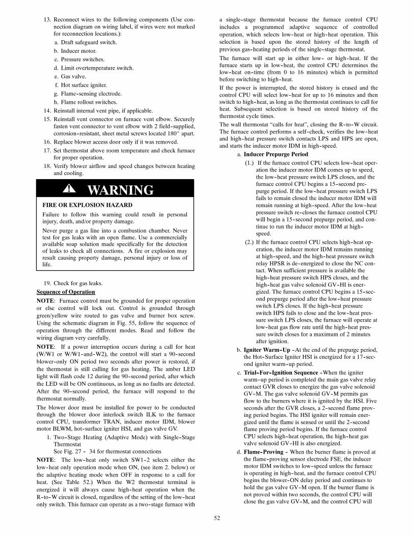
52
13. Reconnect wires to the following components (Use con-nection diagram on wiring label, if wires were not markedfor reconnection locations.):
a. Draft safeguard switch.
b. Inducer motor.
c. Pressure switches.
d. Limit overtemperature switch.
e. Gas valve.
f. Hot surface igniter.
g. Flame--sensing electrode.
h. Flame rollout switches.
14. Reinstall internal vent pipe, if applicable.
15. Reinstall vent connector on furnace vent elbow. Securelyfasten vent connector to vent elbow with 2 field--supplied,corrosion--resistant, sheet metal screws located 180_ apart.
16. Replace blower access door only if it was removed.
17. Set thermostat above room temperature and check furnacefor proper operation.
18. Verify blower airflow and speed changes between heatingand cooling.
FIRE OR EXPLOSION HAZARD
Failure to follow this warning could result in personalinjury, death, and/or property damage.
Never purge a gas line into a combustion chamber. Nevertest for gas leaks with an open flame. Use a commerciallyavailable soap solution made specifically for the detectionof leaks to check all connections. A fire or explosion mayresult causing property damage, personal injury or loss oflife.
! WARNING
19. Check for gas leaks.
Sequence of Operation
NOTE: Furnace control must be grounded for proper operationor else control will lock out. Control is grounded throughgreen/yellow wire routed to gas valve and burner box screw.Using the schematic diagram in Fig. 55, follow the sequence ofoperation through the different modes. Read and follow thewiring diagram very carefully.
NOTE: If a power interruption occurs during a call for heat(W/W1 or W/W1--and--W2), the control will start a 90--secondblower--only ON period two seconds after power is restored, ifthe thermostat is still calling for gas heating. The amber LEDlight will flash code 12 during the 90--second period, after whichthe LED will be ON continuous, as long as no faults are detected.After the 90--second period, the furnace will respond to thethermostat normally.
The blower door must be installed for power to be conductedthrough the blower door interlock switch ILK to the furnacecontrol CPU, transformer TRAN, inducer motor IDM, blowermotor BLWM, hot--surface igniter HSI, and gas valve GV.
1. Two--Stage Heating (Adaptive Mode) with Single--StageThermostatSee Fig. 27 -- 34 for thermostat connections
NOTE: The low--heat only switch SW1--2 selects either thelow--heat only operation mode when ON, (see item 2. below) orthe adaptive heating mode when OFF in response to a call forheat. (See Table 52.) When the W2 thermostat terminal isenergized it will always cause high--heat operation when theR--to--W circuit is closed, regardless of the setting of the low--heatonly switch. This furnace can operate as a two--stage furnace with
a single--stage thermostat because the furnace control CPUincludes a programmed adaptive sequence of controlledoperation, which selects low--heat or high--heat operation. Thisselection is based upon the stored history of the length ofprevious gas--heating periods of the single--stage thermostat.
The furnace will start up in either low-- or high--heat. If thefurnace starts up in low--heat, the control CPU determines thelow--heat on--time (from 0 to 16 minutes) which is permittedbefore switching to high--heat.
If the power is interrupted, the stored history is erased and thecontrol CPU will select low--heat for up to 16 minutes and thenswitch to high--heat, as long as the thermostat continues to call forheat. Subsequent selection is based on stored history of thethermostat cycle times.
The wall thermostat “calls for heat”, closing the R--to--W circuit.The furnace control performs a self--check, verifies the low--heatand high--heat pressure switch contacts LPS and HPS are open,and starts the inducer motor IDM in high--speed.
a. Inducer Prepurge Period(1.) If the furnace control CPU selects low--heat oper-
ation the inducer motor IDM comes up to speed,the low--heat pressure switch LPS closes, and thefurnace control CPU begins a 15--second pre-purge period. If the low--heat pressure switch LPSfails to remain closed the inducer motor IDM willremain running at high--speed. After the low--heatpressure switch re--closes the furnace control CPUwill begin a 15--second prepurge period, and con-tinue to run the inducer motor IDM at high--speed.
(2.) If the furnace control CPU selects high--heat op-eration, the inducer motor IDM remains runningat high--speed, and the high--heat pressure switchrelay HPSR is de--energized to close the NC con-tact. When sufficient pressure is available thehigh--heat pressure switch HPS closes, and thehigh--heat gas valve solenoid GV--HI is ener-gized. The furnace control CPU begins a 15--sec-ond prepurge period after the low--heat pressureswitch LPS closes. If the high--heat pressureswitch HPS fails to close and the low--heat pres-sure switch LPS closes, the furnace will operate atlow--heat gas flow rate until the high--heat pres-sure switch closes for a maximum of 2 minutesafter ignition.
b. Igniter Warm--Up --At the end of the prepurge period,the Hot--Surface Igniter HSI is energized for a 17--sec-ond igniter warm--up period.
c. Trial--For--Ignition Sequence --When the igniterwarm--up period is completed the main gas valve relaycontact GVR closes to energize the gas valve solenoidGV--M. The gas valve solenoid GV--M permits gasflow to the burners where it is ignited by the HSI. Fiveseconds after the GVR closes, a 2--second flame prov-ing period begins. The HSI igniter will remain ener-gized until the flame is sensed or until the 2--secondflame proving period begins. If the furnace controlCPU selects high--heat operation, the high--heat gasvalve solenoid GV--HI is also energized.
d. Flame--Proving -- When the burner flame is proved atthe flame--proving sensor electrode FSE, the inducermotor IDM switches to low--speed unless the furnaceis operating in high--heat, and the furnace control CPUbegins the blower--ON delay period and continues tohold the gas valve GV--M open. If the burner flame isnot proved within two seconds, the control CPU willclose the gas valve GV--M, and the control CPU will
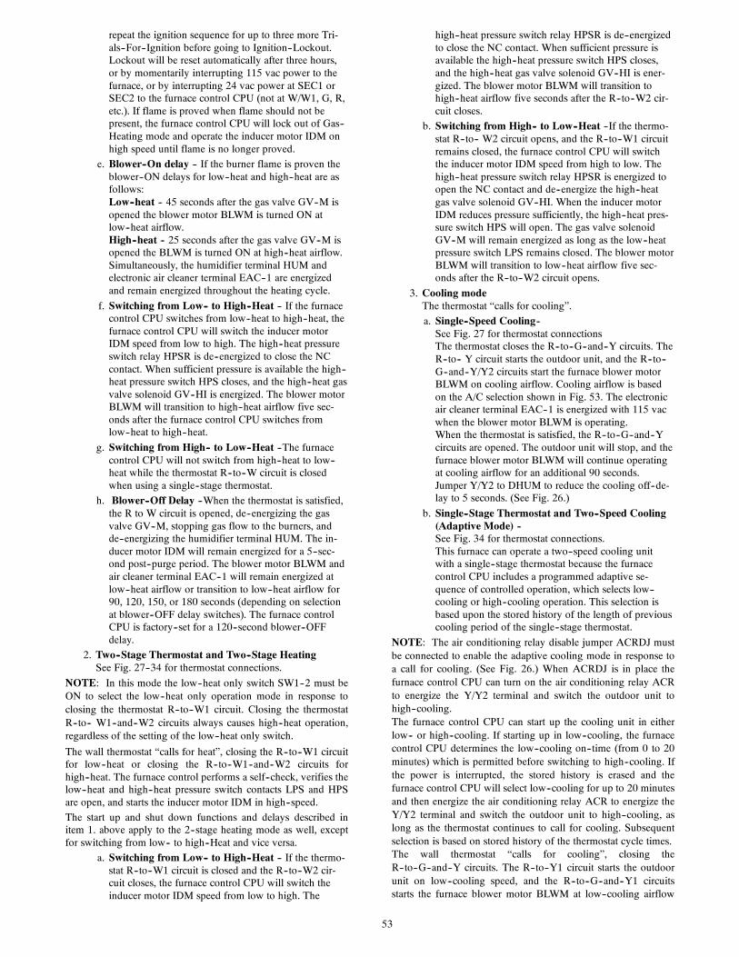
53
repeat the ignition sequence for up to three more Tri-als--For--Ignition before going to Ignition--Lockout.Lockout will be reset automatically after three hours,or by momentarily interrupting 115 vac power to thefurnace, or by interrupting 24 vac power at SEC1 orSEC2 to the furnace control CPU (not at W/W1, G, R,etc.). If flame is proved when flame should not bepresent, the furnace control CPU will lock out of Gas--Heating mode and operate the inducer motor IDM onhigh speed until flame is no longer proved.
e. Blower--On delay -- If the burner flame is proven theblower--ON delays for low--heat and high--heat are asfollows:Low--heat -- 45 seconds after the gas valve GV--M isopened the blower motor BLWM is turned ON atlow--heat airflow.High--heat -- 25 seconds after the gas valve GV--M isopened the BLWM is turned ON at high--heat airflow.Simultaneously, the humidifier terminal HUM andelectronic air cleaner terminal EAC--1 are energizedand remain energized throughout the heating cycle.
f. Switching from Low-- to High--Heat -- If the furnacecontrol CPU switches from low--heat to high--heat, thefurnace control CPU will switch the inducer motorIDM speed from low to high. The high--heat pressureswitch relay HPSR is de--energized to close the NCcontact. When sufficient pressure is available the high--heat pressure switch HPS closes, and the high--heat gasvalve solenoid GV--HI is energized. The blower motorBLWM will transition to high--heat airflow five sec-onds after the furnace control CPU switches fromlow--heat to high--heat.
g. Switching from High-- to Low--Heat --The furnacecontrol CPU will not switch from high--heat to low--heat while the thermostat R--to--W circuit is closedwhen using a single--stage thermostat.
h. Blower--Off Delay --When the thermostat is satisfied,the R to W circuit is opened, de--energizing the gasvalve GV--M, stopping gas flow to the burners, andde--energizing the humidifier terminal HUM. The in-ducer motor IDM will remain energized for a 5--sec-ond post--purge period. The blower motor BLWM andair cleaner terminal EAC--1 will remain energized atlow--heat airflow or transition to low--heat airflow for90, 120, 150, or 180 seconds (depending on selectionat blower--OFF delay switches). The furnace controlCPU is factory--set for a 120--second blower--OFFdelay.
2. Two--Stage Thermostat and Two--Stage HeatingSee Fig. 27--34 for thermostat connections.
NOTE: In this mode the low--heat only switch SW1--2 must beON to select the low--heat only operation mode in response toclosing the thermostat R--to--W1 circuit. Closing the thermostatR--to-- W1--and--W2 circuits always causes high--heat operation,regardless of the setting of the low--heat only switch.
The wall thermostat “calls for heat”, closing the R--to--W1 circuitfor low--heat or closing the R--to--W1--and--W2 circuits forhigh--heat. The furnace control performs a self--check, verifies thelow--heat and high--heat pressure switch contacts LPS and HPSare open, and starts the inducer motor IDM in high--speed.
The start up and shut down functions and delays described initem 1. above apply to the 2--stage heating mode as well, exceptfor switching from low-- to high--Heat and vice versa.
a. Switching from Low-- to High--Heat -- If the thermo-stat R--to--W1 circuit is closed and the R--to--W2 cir-cuit closes, the furnace control CPU will switch theinducer motor IDM speed from low to high. The
high--heat pressure switch relay HPSR is de--energizedto close the NC contact. When sufficient pressure isavailable the high--heat pressure switch HPS closes,and the high--heat gas valve solenoid GV--HI is ener-gized. The blower motor BLWM will transition tohigh--heat airflow five seconds after the R--to--W2 cir-cuit closes.
b. Switching from High-- to Low--Heat --If the thermo-stat R--to-- W2 circuit opens, and the R--to--W1 circuitremains closed, the furnace control CPU will switchthe inducer motor IDM speed from high to low. Thehigh--heat pressure switch relay HPSR is energized toopen the NC contact and de--energize the high--heatgas valve solenoid GV--HI. When the inducer motorIDM reduces pressure sufficiently, the high--heat pres-sure switch HPS will open. The gas valve solenoidGV--M will remain energized as long as the low--heatpressure switch LPS remains closed. The blower motorBLWM will transition to low--heat airflow five sec-onds after the R--to--W2 circuit opens.
3. Cooling modeThe thermostat “calls for cooling”.
a. Single--Speed Cooling--See Fig. 27 for thermostat connectionsThe thermostat closes the R--to--G--and--Y circuits. TheR--to-- Y circuit starts the outdoor unit, and the R--to--G--and--Y/Y2 circuits start the furnace blower motorBLWM on cooling airflow. Cooling airflow is basedon the A/C selection shown in Fig. 53. The electronicair cleaner terminal EAC--1 is energized with 115 vacwhen the blower motor BLWM is operating.When the thermostat is satisfied, the R--to--G--and--Ycircuits are opened. The outdoor unit will stop, and thefurnace blower motor BLWM will continue operatingat cooling airflow for an additional 90 seconds.Jumper Y/Y2 to DHUM to reduce the cooling off--de-lay to 5 seconds. (See Fig. 26.)
b. Single--Stage Thermostat and Two--Speed Cooling(Adaptive Mode) --See Fig. 34 for thermostat connections.This furnace can operate a two--speed cooling unitwith a single--stage thermostat because the furnacecontrol CPU includes a programmed adaptive se-quence of controlled operation, which selects low--cooling or high--cooling operation. This selection isbased upon the stored history of the length of previouscooling period of the single--stage thermostat.
NOTE: The air conditioning relay disable jumper ACRDJ mustbe connected to enable the adaptive cooling mode in response toa call for cooling. (See Fig. 26.) When ACRDJ is in place thefurnace control CPU can turn on the air conditioning relay ACRto energize the Y/Y2 terminal and switch the outdoor unit tohigh--cooling.The furnace control CPU can start up the cooling unit in eitherlow-- or high--cooling. If starting up in low--cooling, the furnacecontrol CPU determines the low--cooling on--time (from 0 to 20minutes) which is permitted before switching to high--cooling. Ifthe power is interrupted, the stored history is erased and thefurnace control CPU will select low--cooling for up to 20 minutesand then energize the air conditioning relay ACR to energize theY/Y2 terminal and switch the outdoor unit to high--cooling, aslong as the thermostat continues to call for cooling. Subsequentselection is based on stored history of the thermostat cycle times.The wall thermostat “calls for cooling”, closing theR--to--G--and--Y circuits. The R--to--Y1 circuit starts the outdoorunit on low--cooling speed, and the R--to--G--and--Y1 circuitsstarts the furnace blower motor BLWM at low--cooling airflow

54
which is the true on--board CF selection as shown in Fig. 53.If the furnace control CPU switches from low--cooling tohigh--cooling, the furnace control CPU will energize the airconditioning relay ACR. When the air conditioning relay ACR isenergized the R--to--Y1--and--Y2 circuits switch the outdoor unitto high--cooling speed, and the R--to--G--and--Y1--and--Y/Y2circuits transition the furnace blower motor BLWM tohigh--cooling airflow. High--cooling airflow is based on the A/Cselection shown in Fig. 53.
NOTE: When transitioning from low--cooling to high--coolingthe outdoor unit compressor will shut down for 1 minute whilethe furnace blower motor BLWM transitions to run athigh--cooling airflow.The electronic air cleaner terminal EAC--1 is energized with 115vac whenever the blower motor BLWM is operating.When the thermostat is satisfied, the R--to--G--and--Y circuit areopened. The outdoor unit stops, and the furnace blower BLWMand electronic air cleaner terminal EAC--1 will remain energizedfor an additional 90 seconds. Jumper Y1 to DHUM to reduce thecooling off--delay to 5 seconds. (See Fig. 26.)
c. Two--Stage Thermostat and Two--Speed CoolingSee Fig. 33 for thermostat connections
NOTE: The air conditioning relay disable jumper ACRDJ mustbe disconnected to allow thermostat control of the outdoor unitstaging. (See Fig. 26.)
The thermostat closes the R--to--G--and--Y1 circuits forlow--cooling or closes the R--to--G--and--Y1--and--Y2 circuits forhigh--cooling. The R--to--Y1 circuit starts the outdoor unit onlow--cooling speed, and the R--to--G--and--Y1 circuit starts thefurnace blower motor BLWM at low--cooling airflow which is thetrue on--board CF selection as shown in Table 4 and Fig. 53. TheR--to--Y1--and--Y2 circuits start the outdoor unit on high--coolingspeed, and the R--to-- G--and--Y/Y2 circuits start the furnaceblower motor BLWM at high--cooling airflow. High--coolingairflow is based on the A/C (air conditioning) selection shown inFig. 53.The electronic air cleaner terminal EAC--1 is energized with 115vac whenever the blower motor BLWM is operating.When the thermostat is satisfied, the R--to--G--and--Y1 or R--to--G--and--Y1--and--Y2 circuits are opened. The outdoor unit stops,and the furnace blower BLWM and electronic air cleaner terminalEAC--1 will remain energized for an additional 90 seconds.Jumper Y1 to DHUM to reduce the cooling off--delay to 5seconds. (See Fig. 26.)
4. Thermidistat ModeSee Fig. 27--29 for thermostat connections.The dehumidification output, DHUM on the Thermidistatshould be connected to the furnace control thermostat ter-minal DHUM. When there is a dehumidify demand, theDHUM input is activated, which means 24 vac signal isremoved from the DHUM input terminal. In other words,the DHUM input logic is reversed. The DHUM input isturned ON when no dehumidify demand exists. Once 24vac is detected by the furnace control on the DHUM input,the furnace control operates in Thermidistat mode. If theDHUM input is low for more than 48 hours, the furnacecontrol reverts back to non--Thermidistat mode.The cooling operation described in item 3. above also ap-plies to operation with a Thermidistat. The exceptions arelisted below:
a. Low cooling--When the R--to--G--and--Y1 circuit isclosed and there is a demand for dehumidification, thefurnace blower motor BLWM will drop the blowerairflow to 90 percent of low--cooling airflow which isthe true on--board CF selection as shown in Table 4and Fig. 53.
b. High cooling--When the R--to--G--and Y/Y2 circuit isclosed and there is a demand for dehumidification, thefurnace blower motor BLWM will drop the blowerairflow to 90 percent of high--cooling airflow. High--cooling airflow is based on the A/C (air conditioning)selection shown in Fig. 53.
c. Cooling off--delay--When the “call for cooling” issatisfied and there is a demand for dehumidification,the cooling blower--off delay is decreased from 90seconds to 5 seconds.
5. Continuous Blower ModeWhen the R--to--G circuit is closed by the thermostat, theblower motor BLWM will operate at continuous blowerairflow. Continuous blower airflow selection is initiallybased on the CF selection shown in Table 4 and and Fig.53. Factory default is shown in Table 4. Terminal EAC--1is energized as long as the blower motor BLWM is ener-gized.During a call for heat, the furnace control CPU will transi-tion the blower motor BLWM to continuous blower air-flow or low--heat airflow whichever is lowest. The blowermotor BLWM will remain ON until the main burners ig-nite then shut OFF and remain OFF for the blower--ONdelay (45 seconds in low--heat, and 25 seconds in high--heat), allowing the furnace heat exchangers to heat upmore quickly, then restarts at the end of the blower--ONdelay period at low--heat or high--heat airflow, respective-ly.The blower motor BLWM will revert to continuous--blow-er airflow after the heating cycle is completed. In high--heat, the furnace control CPU will drop the blower motorBLWM to low--heat airflow during the selected blower--OFF delay period before transitioning to continuous--blower airflow.When the thermostat “calls for low--cooling”, the blowermotor BLWM will switch to operate at low--cooling air-flow. When the thermostat is satisfied, the blower motorBLWM will operate an additional 90 seconds at low--cool-ing airflow before transitioning back to continuous--blow-er airflow.When the thermostat “calls for high--cooling”, the blowermotor BLWM will operate at high cooling airflow. Whenthe thermostat is satisfied, the blower motor BLWM willoperate an additional 90 seconds at high--cooling airflowbefore transitioning back to continuous--blower airflow.When the R--to--G circuit is opened, the blower motorBLWM will continue operating for an additional 5 sec-onds, if no other function requires blower motor BLWMoperation.Continuous Blower Speed Selection from ThermostatTo select different continuous--blower airflow from theroom thermostat, momentarily turn off the FAN switch orpush button on the room thermostat for 1--3 seconds afterthe blower motor BLWM is operating. The furnace controlCPU will shift the continuous--blower airflow from thefactory setting to the next highest CF selection airflow asshown in Table 4 and Fig. 53. Momentarily turning off theFAN switch again at the thermostat will shift the continu-ous--blower airflow up one more increment. If you repeatthis procedure enough you will eventually shift the contin-uous--blower airflow to the lowest CF selection as shownin Table 4 and Fig. 53. The selection can be changed asmany times as desired and is stored in the memory to beautomatically used following a power interruption.
NOTE: If the blower--off delay is set to the maximum, theadjustable continuous--fan feature is locked (i.e., fan speed cannotbe changed from its current setting).
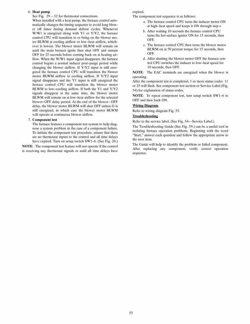
55
6. Heat pumpSee Fig. 29 -- 32 for thermostat connections.When installed with a heat pump, the furnace control auto-matically changes the timing sequence to avoid long blow-er off times during demand defrost cycles. WheneverW/W1 is energized along with Y1 or Y/Y2, the furnacecontrol CPU will transition to or bring on the blower mo-tor BLWM at cooling airflow or low--heat airflow, which-ever is lowest. The blower motor BLWM will remain onuntil the main burners ignite then shut OFF and remainOFF for 25 seconds before coming back on at heating air-flow. When the W/W1 input signal disappears, the furnacecontrol begins a normal inducer post--purge period whilechanging the blower airflow. If Y/Y2 input is still ener-gized the furnace control CPU will transition the blowermotor BLWM airflow to cooling airflow. If Y/Y2 inputsignal disappears and the Y1 input is still energized thefurnace control CPU will transition the blower motorBLWM to low--cooling airflow. If both the Y1 and Y/Y2signals disappear at the same time, the blower motorBLWM will remain on at low--heat airflow for the selectedblower--OFF delay period. At the end of the blower-- OFFdelay, the blower motor BLWM will shut OFF unless G isstill energized, in which case the blower motor BLWMwill operate at continuous blower airflow.
7. Component testThe furnace features a component test system to help diag-nose a system problem in the case of a component failure.To initiate the component test procedure, ensure that thereare no thermostat inputs to the control and all time delayshave expired. Turn on setup switch SW1--6. (See Fig. 26.)
NOTE: The component test feature will not operate if the controlis receiving any thermostat signals or until all time delays have
expired.The component test sequence is as follows:
a. The furnace control CPU turns the inducer motor ONat high--heat speed and keeps it ON through step c.
b. After waiting 10 seconds the furnace control CPUturns the hot surface igniter ON for 15 seconds, thenOFF.
c. The furnace control CPU then turns the blower motorBLWM on at 50 percent torque for 15 seconds, thenOFF.
d. After shutting the blower motor OFF the furnace con-trol CPU switches the inducer to low--heat speed for10 seconds, then OFF.
NOTE: The EAC terminals are energized when the blower isoperating.After the component test is completed, 1 or more status codes 11or 25 will flash. See component test section or Service Label (Fig.54) for explanation of status codes.
NOTE: To repeat component test, turn setup switch SW1--6 toOFF and then back ON.
Wiring Diagram
Refer to wiring diagram Fig. 55.
Troubleshooting
Refer to the service label. (See Fig. 54—Service Label.)
The Troubleshooting Guide (See Fig. 59.) can be a useful tool inisolating furnace operation problems. Beginning with the word“Start,” answer each question and follow the appropriate arrow tothe next item.
The Guide will help to identify the problem or failed component.After replacing any component, verify correct operationsequence.
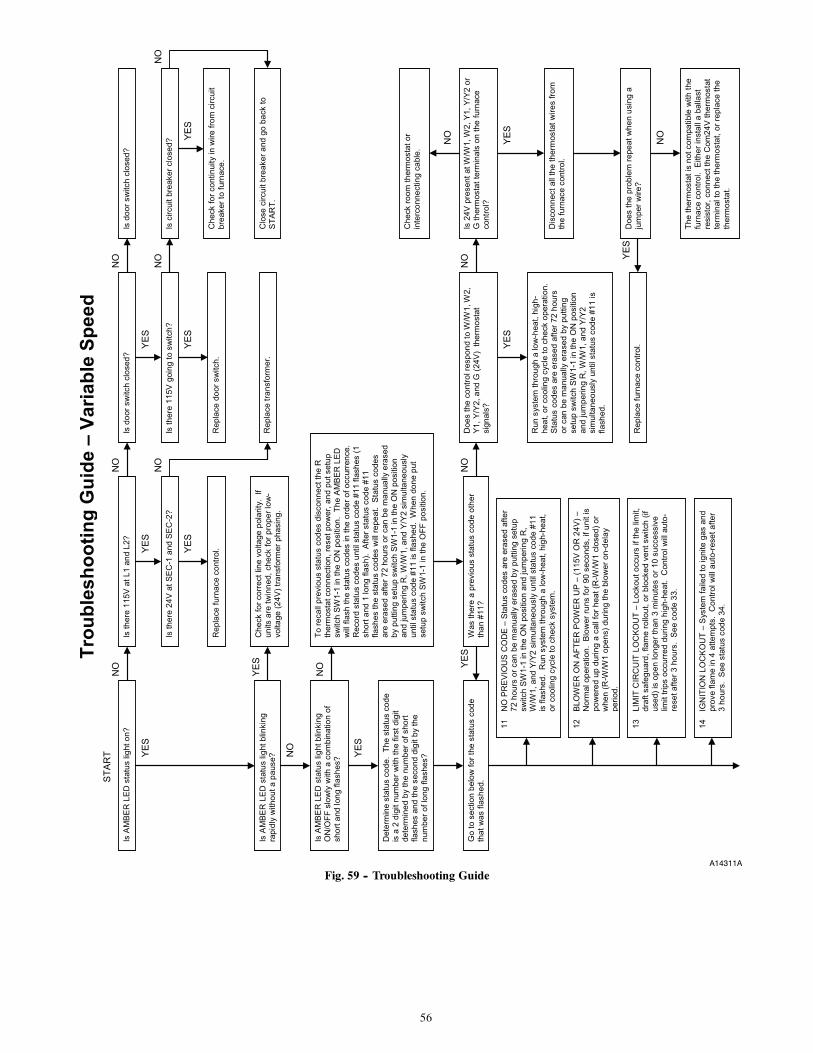
56
Is A
MB
ER
LE
D s
tatu
s lig
ht o
n?
Is th
ere
24V
at S
EC
-1 a
nd S
EC
-2?
Is th
ere
115V
at L
1 an
d L2
?
Rep
lace
furn
ace
cont
rol.
Is d
oor s
witc
h cl
osed
?
Rep
lace
tran
sfor
mer
.
Rep
lace
doo
r sw
itch.
Is th
ere
115V
goi
ng to
sw
itch?
Is d
oor s
witc
h cl
osed
?
Is c
ircui
t bre
aker
clo
sed?
Che
ck fo
r con
tinui
ty in
wire
from
circ
uit
brea
ker t
o fu
rnac
e.
Clo
se c
ircui
t bre
aker
and
go
back
to
STA
RT.
Is
AM
BE
R L
ED
sta
tus
light
blin
king
ra
pidl
y w
ithou
t a p
ause
?
Che
ck fo
r cor
rect
line
vol
tage
pol
arity
. If
units
are
twin
ned,
che
ck fo
r pro
per l
ow-
volta
ge (2
4V) t
rans
form
er p
hasi
ng.
Is A
MB
ER
LE
D s
tatu
s lig
ht b
linki
ng
ON
/OFF
slo
wly
with
a c
ombi
natio
n of
sh
ort a
nd lo
ng fl
ashe
s?
Det
erm
ine
stat
us c
ode.
The
sta
tus
code
is
a 2
dig
it nu
mbe
r with
the
first
dig
it de
term
ined
by
the
num
ber o
f sho
rt fla
shes
and
the
seco
nd d
igit
by th
e nu
mbe
r of l
ong
flash
es?
To re
call
prev
ious
sta
tus
code
s di
scon
nect
the
R
ther
mos
tat c
onne
ctio
n, re
set p
ower
, and
put
set
up
switc
h SW
1-1
in th
e O
N p
ositi
on.
The
AM
BE
R L
ED
w
ill fl
ash
the
stat
us c
odes
in th
e or
der o
f occ
urre
nce.
R
ecor
d st
atus
cod
es u
ntil
stat
us c
ode
#11
flash
es (1
sh
ort a
nd 1
long
flas
h).
Afte
r sta
tus
code
#11
fla
shes
the
stat
us c
odes
will
repe
at.
Sta
tus
code
s ar
e er
ased
afte
r 72
hour
s or
can
be
man
ually
era
sed
by p
uttin
g se
tup
switc
h SW
1-1
in th
e O
N p
ositi
on
and
jum
perin
g R
, W/W
1, a
nd Y
/Y2
sim
ulta
neou
sly
until
sta
tus
code
#11
is fl
ashe
d. W
hen
done
put
se
tup
switc
h SW
1-1
in th
e O
FF p
ositi
on.
Was
ther
e a
prev
ious
sta
tus
code
oth
er
than
#11
?
Go
to s
ectio
n be
low
for t
he s
tatu
s co
de
that
was
flas
hed.
Doe
s th
e co
ntro
l res
pond
to W
/W1,
W2,
Y1
, Y/Y
2, a
nd G
(24V
) th
erm
osta
t si
gnal
s?
Run
sys
tem
thro
ugh
a lo
w-h
eat,
high
-he
at, o
r coo
ling
cycl
e to
che
ck o
pera
tion.
S
tatu
s co
des
are
eras
ed a
fter 7
2 ho
urs
or c
an b
e m
anua
lly e
rase
d by
put
ting
setu
p sw
itch
SW1-
1 in
the
ON
pos
ition
an
d ju
mpe
ring
R, W
/W1,
and
Y/Y
2 si
mul
tane
ousl
y un
til s
tatu
s co
de #
11 is
fla
shed
.
Is 2
4V p
rese
nt a
t W/W
1, W
2, Y
1, Y
/Y2
or
G th
erm
osta
t ter
min
als
on th
e fu
rnac
e co
ntro
l?
Che
ck ro
om th
erm
osta
t or
inte
rcon
nect
ing
cabl
e.
Dis
conn
ect a
ll th
e th
erm
osta
t wire
s fro
m
the
furn
ace
cont
rol.
Doe
s th
e pr
oble
m re
peat
whe
n us
ing
a ju
mpe
r wire
? R
epla
ce fu
rnac
e co
ntro
l.
The
ther
mos
tat i
s no
t com
patib
le w
ith th
e fu
rnac
e co
ntro
l. E
ither
inst
all a
bal
last
re
sist
or, c
onne
ct th
e C
om24
V th
erm
osta
t te
rmin
al to
the
ther
mos
tat,
or re
plac
e th
e th
erm
osta
t.
YES
NO
YES
YES
YES
YES
YES
YES
Y
ES
YES
YES
STA
RT
YES
YES
NO
NO
NO
NO
N
O
NO
NO
N
O
NO
NO
NO
Trou
bles
hoot
ing
Gui
de –
Var
iabl
e Sp
eed
11
NO
PR
EV
IOU
S C
OD
E –
Sta
tus
code
s ar
e er
ased
afte
r 72
hou
rs o
r can
be
man
ually
era
sed
by p
uttin
g se
tup
switc
h SW
1-1
in th
e O
N p
ositi
on a
nd ju
mpe
ring
R,
W/W
1, a
nd Y
/Y2
sim
ulta
neou
sly
until
sta
tus
code
#11
is
flas
hed.
Run
sys
tem
thro
ugh
a lo
w-h
eat,
high
-hea
t, or
coo
ling
cycl
e to
che
ck s
yste
m.
12
BLO
WE
R O
N A
FTE
R P
OW
ER
UP
– (1
15V
OR
24V
) –
Nor
mal
ope
ratio
n. B
low
er ru
ns fo
r 90
seco
nds,
if u
nit i
s po
wer
ed u
p du
ring
a ca
ll fo
r hea
t (R
-W/W
1 cl
osed
) or
whe
n (R
-W/W
1 op
ens)
dur
ing
the
blow
er o
n-de
lay
perio
d.
13
LIM
IT C
IRC
UIT
LO
CK
OU
T –
Lock
out o
ccur
s if
the
limit,
dr
aft s
afeg
uard
, fla
me
rollo
ut, o
r blo
cked
ven
t sw
itch
(if
used
) is
open
long
er th
an 3
min
utes
or 1
0 su
cces
sive
lim
it tri
ps o
ccur
red
durin
g hi
gh-h
eat.
Con
trol w
ill au
to-
rese
t afte
r 3 h
ours
. S
ee c
ode
33.
14
IGN
ITIO
N L
OC
KO
UT
– S
yste
m fa
iled
to ig
nite
gas
and
pr
ove
flam
e in
4 a
ttem
pts.
Con
trol w
ill a
uto-
rese
t afte
r 3
hour
s. S
ee s
tatu
s co
de 3
4.
A14311A
Fig. 59 -- Troubleshooting Guide

57
25
INV
ALI
D M
OD
EL
SELE
CTI
ON
OR
SE
TUP
ERR
OR
– If
sta
tus
code
25
only
fla
shes
4 ti
mes
on
pow
er-u
p th
e co
ntro
l is
mis
sing
its
mod
el p
lug
PL4
and
is
defa
ultin
g to
the
mod
el s
elec
tion
stor
ed in
m
emor
y. I
f sta
tus
code
25
flash
es
cont
inuo
usly
it c
ould
indi
cate
any
of t
he
follo
win
g:
-
Mod
el p
lug
PL4
is m
issi
ng a
nd th
ere
is
no v
alid
mod
el s
tore
d in
per
man
ent
mem
ory.
Thi
s w
ill h
appe
n if
you
forg
et
to in
stal
l the
mod
el p
lug
PL4
on
a se
rvic
e re
plac
emen
t con
trol.
-
Ther
mos
tat c
all w
ith S
W1-
1 O
N.
-
Ther
mos
tat c
all w
ith S
W1-
6 O
N.
-
SW1-
1 an
d SW
1-6
both
ON
.
- Tw
o di
ffere
nt fu
rnac
e m
odel
s tw
inne
d.
-
If re
plac
ing
a co
ntro
l, be
sur
e to
use
co
rrec
t ver
sion
(V##
) loc
ated
on
cont
rol
boar
d) M
odel
s su
ppor
ted
shou
ld b
e lis
ted.
31
HIG
H-H
EA
T P
RE
SSU
RE
SW
ITC
H O
R
REL
AY D
ID N
OT
CLO
SE O
R
RE
OP
EN
ED
- C
heck
for:
-
Con
trol r
elay
may
be
defe
ctiv
e.
-
Gas
val
ve is
mis
wire
d.
-
See
sta
tus
code
32.
21
GA
S H
EA
TIN
G L
OC
KO
UT
– Tu
rn o
ff po
wer
and
wai
t 5 m
inut
es to
retry
. C
heck
fo
r:
- S
tuck
clo
sed
gas
valv
e re
lay
on c
ontro
l.
- M
isw
ire o
r sho
rt to
gas
val
ve w
ire.
22
AB
NO
RM
AL
FLA
ME
-PR
OV
ING
SIG
NA
L Fl
ame
is p
rove
d w
hile
gas
val
ve is
de-
ener
gize
d. I
nduc
er w
ill ru
n un
til fa
ult i
s cl
eare
d. C
heck
for:
-
Stu
ck o
p en
or le
aky
gas
valv
e.
23
PRES
SUR
E SW
ITC
H D
ID N
OT
OPE
N –
C
heck
for:
- O
bstru
cted
pre
ssur
e tu
be.
- P
ress
ure
switc
h st
uck
clos
ed.
24
SE
CO
ND
AR
Y V
OLT
AG
E F
US
E IS
OPE
N
Che
ck fo
r:
- S
hort
circ
uit i
n se
cond
ary
volta
ge (2
4V)
wiri
ng in
clud
ing
ther
mos
tat l
eads
. D
isco
nnec
t the
rmos
tat l
eads
to is
olat
e sh
ort c
ircui
t.
32
LOW
-HEA
T PR
ESSU
RE
SWIT
CH
DID
N
OT
CLO
SE
OR
RE
OP
EN
ED
– If
ope
n lo
nger
than
5 m
inut
es, i
nduc
er s
huts
off
for 1
5 m
inut
es b
efor
e re
try.
If op
ens
durin
g bl
ower
on-
dela
y pe
riod,
blo
wer
will
co
me
on fo
r the
sel
ecte
d bl
ower
off-
dela
y.
Che
ck fo
r:
- P
rope
r ven
t siz
ing.
-
Low
indu
cer v
olta
ge (1
15V)
. -
Low
inle
t gas
pre
ssur
e (if
LG
PS
used
). -
Inad
equa
te c
ombu
stio
n ai
r sup
ply.
-
Dis
conn
ecte
d or
obs
truct
ed p
ress
ure
tubi
ng.
- D
efec
tive
indu
cer m
otor
. -
Def
ectiv
e pr
essu
re s
witc
h.
- E
xces
sive
win
d.
-R
estri
cted
ven
t.
33
LIM
IT C
IRC
UIT
FAU
LT –
Indi
cate
s th
e lim
it, d
raft
safe
guar
d, fl
ame
rollo
ut, o
r bl
ocke
d ve
nt s
witc
h* (i
f use
d) is
ope
n or
th
e fu
rnac
e is
ope
ratin
g in
hig
h-he
at o
nly
mod
e du
e to
2 s
ucce
ssiv
e lo
w-h
eat l
imit
trips
. B
low
er w
ill ru
n fo
r 4 m
in. o
r unt
il op
en s
witc
h re
mak
es w
hich
ever
is lo
nger
. If
open
long
er th
an 3
min
., co
de c
hang
es
to lo
ckou
t #13
. If
open
less
than
3 m
in.
stat
us c
ode
#33
cont
inue
s to
flas
h un
til
blow
er s
huts
off.
Fla
me
rollo
ut s
witc
h an
d B
VS
S re
quire
s m
anua
l res
et.
Che
ck fo
r:
- D
irty
filte
r or r
estri
cted
duc
t sys
tem
. -
Loos
e bl
ower
whe
el.
- D
efec
tive
switc
h or
con
nect
ions
. -
Inad
equa
te c
ombu
stio
n ai
r sup
ply
(flam
e ro
llout
sw
itch
open
). -
Res
trict
ed v
ent.
- P
rope
r ven
t siz
ing.
-
Exc
essi
ve w
ind.
-
Blo
wer
mot
or n
ot o
pera
ting
34
IGN
ITIO
N P
RO
VIN
G F
AIL
UR
E –
If fla
me
is
not s
ense
d du
ring
the
trial
for i
gniti
on
perio
d, th
e co
ntro
l will
repe
at th
e ig
nitio
n se
quen
ce 3
mor
e tim
es b
efor
e lo
ckou
t #14
oc
curs
. If
flam
e si
gnal
is lo
st d
urin
g th
e bl
ower
on-
dela
y pe
riod,
blo
wer
will
com
e on
fo
r the
sel
ecte
d bl
ower
off-
dela
y. C
heck
th
e fo
llow
ing
item
s fir
st b
efor
e pr
ocee
ding
to
the
next
ste
p.
-
Gas
val
ve tu
rned
off.
-
Man
ual s
hut-o
ff va
lve.
-
Gre
en/Y
ello
w w
ire M
US
T be
con
nect
ed
to fu
rnac
e sh
eet m
etal
. -
Flam
e se
nsor
mus
t not
be
grou
nded
. To
det
erm
ine
whe
ther
the
prob
lem
is in
the
gas
valv
e, ig
nite
r, or
flam
e se
nsor
the
syst
em c
an b
e op
erat
ed in
com
pone
nt te
st
mod
e. T
o ch
eck
the
igni
ter r
emov
e th
e R
th
erm
osta
t con
nect
ion
from
the
cont
rol,
rese
t pow
er, a
nd p
ut s
etup
sw
itch
SW1-
6 in
th
e O
N p
ositi
on to
sta
rt th
e co
mpo
nent
test
. D
oes
the
igni
ter g
low
ora
nge/
whi
te b
y th
e en
d of
the
15 s
econ
d w
arm
-up
perio
d?
Unp
lug
igni
ter h
arne
ss fr
om c
ontro
l and
re
peat
com
pone
nt te
st b
y tu
rnin
g se
tup
switc
h SW
1-6
OFF
and
then
bac
k O
N.
Che
ck fo
r 115
V b
etw
een
pin
3 an
d N
EU
TRA
L-L2
on
the
cont
rol.
Was
115
V
pres
ent f
or th
e 15
sec
ond
perio
d?
Che
ck c
onne
ctio
ns a
nd re
try.
If cu
rren
t is
near
typi
cal v
alue
(4
.0-6
.0 n
omin
al) a
nd b
urne
rs
will
not
sta
y on
, rep
eat c
heck
in
hig
h-he
at.
If bu
rner
s w
ill st
ill no
t sta
y on
repl
ace
cont
rol.
If b
urne
rs o
pera
te in
hi
gh-h
eat t
hen
switc
h to
low
-he
at, c
heck
man
ifold
pr
essu
re.
If O
K, c
heck
bu
rner
car
ryov
er a
nd fl
ame
sens
or lo
catio
n.
Cle
an fl
ame
sens
or w
ith fi
ne s
teel
woo
l an
d re
chec
k cu
rren
t. N
omin
al c
urre
nt is
4.
0 to
6.0
mic
roam
ps.
Is c
urre
nt n
ear t
ypic
al v
alue
?
Rep
lace
ele
ctro
de.
Will
mai
n bu
rner
s ig
nite
and
sta
y on
? R
epla
ce fu
rnac
e co
ntro
l.
Fixe
d.
NO
YES
YES
YES
NO
NO
45
CO
NTR
OL
CIR
CU
ITR
Y LO
CK
OU
T A
uto-
rese
t af
ter 1
hou
r loc
kout
due
to
: -
Flam
e ci
rcui
t fai
lure
. -
Gas
val
ve re
lay
stuc
k op
en.
- S
oftw
are
chec
k er
ror.
Res
et p
ower
to c
lear
lo
ckou
t. R
epla
ce c
ontro
l if
code
repe
ats.
Rep
lace
furn
ace
cont
rol.
Che
ck fo
r con
tinui
ty in
the
harn
ess
and
igni
ter.
Rep
lace
de
fect
ive
com
pone
nt.
Rec
onne
ct th
e R
ther
mos
tat l
ead
and
set
ther
mos
tat t
o ca
ll fo
r hea
t. C
onne
ct
voltm
eter
acr
oss
gas
valv
e co
nnec
tions
. D
oes
gas
valv
e re
ceiv
e 24
V?
Doe
s ga
s va
lve
open
and
allo
w g
as to
flo
w?
Do
the
mai
n bu
rner
s ig
nite
?
Do
the
mai
n bu
rner
s st
ay o
n?
Allo
w b
low
er to
com
e on
and
re
peat
test
to c
heck
for
inte
rmitt
ent o
pera
tion.
Che
ck th
at a
ll ga
s va
lves
are
tu
rned
on.
Rep
lace
val
ve.
Che
ck c
onne
ctio
ns.
If O
K,
repl
ace
cont
rol.
Che
ck fo
r: -
Inad
equa
te fl
ame
carr
yove
r or
roug
h ig
nitio
n.
- Lo
w in
let g
as p
ress
ure.
-
Pro
per f
iring
rate
. -
Blo
cked
or i
ncor
rect
car
ry-
over
gap
. (.0
45” n
omin
al)
Rep
eat c
all f
or h
eat a
nd c
heck
flam
e se
nsor
cur
rent
dur
ing
trial
for i
gniti
on
perio
d. I
s th
e D
C m
icro
amps
bel
ow 0
.5?
YES
YES
YES
YES
YES
NO
NO
NO
NO
NO
NO
43
LOW
-HEA
T PR
ESSU
RE
SWIT
CH
O
PE
N W
HIL
E H
IGH
-HE
AT
PRES
SUR
E SW
ITC
H IS
CLO
SED
-
Che
ck fo
r: -
Low
-hea
t pre
ssur
e sw
itch
stuc
k op
en.
- D
isco
nnec
ted
or o
bstru
cted
pr
essu
re tu
be.
- M
isw
ired
pres
sure
sw
itche
s.
- Lo
w in
let g
as p
ress
ure
(if L
GP
S us
ed).
* B
lock
ed v
ent s
witc
h us
ed in
Chi
mne
y A
dapt
er K
it
A14311B
Fig. 59 -- Troubleshooting Guide (Continued)

58
PARTS REPLACEMENT INFORMATION GUIDE
CASING GROUP
Outer door
Blower door
Top filler plate
Bottom filler plate
Bottom enclosure
ELECTRICAL GROUP
Control bracket
Junction box
Limit switch(es)
Circuit board
Door switch
Transformer
Wiring harness 115v
Wiring harness 24v
BLOWER GROUP
Blower housing
Blower cutoff
Blower motor
Blower wheel
Capacitor (where used)
Capacitor strap (where used)
Grommet
Power choke (where used)
GAS CONTROL GROUP
Manifold
Burner assembly
Orifice
Flame sensor
Hot surface igniter
Gas valve
Manual reset limit switches
Burner support assembly
HEAT EXCHANGER GROUP
Heat exchanger cell
Cell panel
Lox NOx baffle (California models only)
INDUCER GROUP
Housing assembly
Pressure switch
Inducer motor
Inducer wheel
Vent elbow assembly
Draft safeguard switch
TO OBTAIN INFORMATION ON PARTS: Consult your installing dealer or classified section of your local telephone directory under“Heating Equipment” or “Air Conditioning Contractors and Systems” headings for dealer listing by brand name or contact:
CARRIER CORPORATIONConsumer Relations Department
P.O. Box 4808Syracuse, New York 13221--4808
1--800--CARRIERHave available the model number, series number, and serial number located on the unit rating plate to ensure correct replacement part.
Example of Model Number
MODELAFUENOX
MAJORSERIES
HTGINPUT
MOTORTYPE
WIDTHVOLT-AGE
MINORSERIES
CLGCAPACITY
58TP 0 A 070 V 17 -- -- 16WARNING: Improper installation, adjustment, alteration, service, or maintenance can cause personal injury, property damage, or death.Consult a qualified installer, service agency, or your local gas supplier for information or assistance. The qualified installer or service agencymust use only factory--authorized replacement parts, kits, or accessories when modifying this product.
Copyright 2019 Carrier Corp. S 7310 W. Morris St. S Indianapolis, IN 46231
Manufacturer reserves the right to change, at any time, specifications and designs without notice and without obligations.
Catalog No: 58TP0A---01SIReplaces: NEW
Edition Date: 3/19