Installation, Start-Up and Service · PDF fileAllow flexibility in suction line so compressor...
20
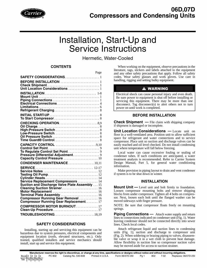
Manufacturer reserves the right to discontinue, or change at any time, specifications or designs without notice and without incurring obligations. PC 802 Catalog No. 530-608 Printed in U.S.A. Form 06/07D-3SI Pg 1 802 7-02 Replaces: 06/07D-2SI Book 2 2 4 4 Tab 1b 2a 2b 3a Installation, Start-Up and Service Instructions Hermetic, Water-Cooled CONTENTS Page SAFETY CONSIDERATIONS . . . . . . . . . . . . . . . . . . . . . . 1 BEFORE INSTALLATION . . . . . . . . . . . . . . . . . . . . . . . . . 1 Check Shipment. . . . . . . . . . . . . . . . . . . . . . . . . . . . . . . . . . 1 Unit Location Considerations . . . . . . . . . . . . . . . . . . . . 1 INSTALLATION . . . . . . . . . . . . . . . . . . . . . . . . . . . . . . . . . 1-8 Mount Unit . . . . . . . . . . . . . . . . . . . . . . . . . . . . . . . . . . . . . . . 1 Piping Connections . . . . . . . . . . . . . . . . . . . . . . . . . . . . . . 1 Electrical Connections . . . . . . . . . . . . . . . . . . . . . . . . . . . 4 Limitations . . . . . . . . . . . . . . . . . . . . . . . . . . . . . . . . . . . . . . . 6 Refrigerant Charging . . . . . . . . . . . . . . . . . . . . . . . . . . . . . 8 INITIAL START-UP . . . . . . . . . . . . . . . . . . . . . . . . . . . . . . . . 8 To Start Compressor . . . . . . . . . . . . . . . . . . . . . . . . . . . . . 8 CHECKING OPERATION. . . . . . . . . . . . . . . . . . . . . . . . . 8,9 Oil Charge. . . . . . . . . . . . . . . . . . . . . . . . . . . . . . . . . . . . . . . . 8 High-Pressure Switch . . . . . . . . . . . . . . . . . . . . . . . . . . . . 8 Low-Pressure Switch. . . . . . . . . . . . . . . . . . . . . . . . . . . . . 8 Oil Pressure Switch . . . . . . . . . . . . . . . . . . . . . . . . . . . . . . 8 Time Guard® Control . . . . . . . . . . . . . . . . . . . . . . . . . . . . . 8 CAPACITY CONTROL . . . . . . . . . . . . . . . . . . . . . . . . . . 9,10 Control Set Point . . . . . . . . . . . . . . . . . . . . . . . . . . . . . . . . . 9 To Regulate Control Set Point . . . . . . . . . . . . . . . . . . . . 9 Pressure Differential Adjustment . . . . . . . . . . . . . . . . . 9 Capacity Control Pressure . . . . . . . . . . . . . . . . . . . . . . 10 CONDENSER MAINTENANCE . . . . . . . . . . . . . . . . . 10,11 SERVICE . . . . . . . . . . . . . . . . . . . . . . . . . . . . . . . . . . . . . 12-17 Service Notes . . . . . . . . . . . . . . . . . . . . . . . . . . . . . . . . . . . 12 Testing Oil Pump . . . . . . . . . . . . . . . . . . . . . . . . . . . . . . . . 12 Cylinder Heads . . . . . . . . . . . . . . . . . . . . . . . . . . . . . . . . . . 14 Service Replacement Compressors . . . . . . . . . . . . . 14 Suction and Discharge Valve Plate Assembly . . . 15 Cleaning Suction Strainer . . . . . . . . . . . . . . . . . . . . . . . 16 Motor Replacement . . . . . . . . . . . . . . . . . . . . . . . . . . . . . 16 Terminal Plate Assembly . . . . . . . . . . . . . . . . . . . . . . . . 16 Compressor Running Gear Removal . . . . . . . . . . . . 16 Compressor Running Gear Replacement. . . . . . . . 17 COMPRESSOR MOTOR BURNOUT . . . . . . . . . . . . . . 17 Clean-Up Procedure . . . . . . . . . . . . . . . . . . . . . . . . . . . . . 17 TROUBLESHOOTING. . . . . . . . . . . . . . . . . . . . . . . . . .18,19 SAFETY CONSIDERATIONS Installing, starting up and servicing this equipment can be hazardous due to system pressures, electrical components and equipment location (roofs, elevated structures, etc.). Only trained, qualified installers and service mechanics should install, start up and service this equipment. When working on the equipment, observe precautions in the literature, tags, stickers and labels attached to the equipment and any other safety precautions that apply. Follow all safety codes. Wear safety glasses and work gloves. Use care in handling, rigging and setting bulky equipment. BEFORE INSTALLATION Check Shipment — File claim with shipping company if shipment is damaged or incomplete. Unit Location Considerations — Locate unit on floor in a well-ventilated area. Position unit to allow sufficient space for refrigerant and water connections and to service compressor. Place unit so suction and discharge valves can be easily reached and oil level checked. Do not install condensing unit where temperature will fall below freezing. Local water can cause excessive fouling or sealing of condenser tubes. If such conditions are anticipated, a water treatment analysis is recommended. Refer to Carrier System Design Manual, Part 5, for general water conditioning information. Make provision in piping layout to drain and vent condenser if system is to be shut down in winter. INSTALLATION Mount Unit — Level unit and bolt firmly to foundation. Loosen compressor mounting bolts and remove shipping blocks from under compressor. Tighten all 4 bolts on compres- sor. Next, loosen each bolt until the flanged washer can be moved sideways with finger pressure. NOTE: Be sure that compressor floats freely on mounting springs. Piping Connections — Attach water supply and return lines to connections indicated on condenser unit (Fig. 1). Water leaving condenser should not be connected directly into sewer lines. Check local codes. Attach refrigerant liquid and suction lines to condensing units (Fig. 1); suction and discharge to compressor unit (Fig. 2). When soldering or brazing piping to valves, disassem- ble valve or wrap it in a wet cloth to prevent heat damage. Allow flexibility in suction line so compressor suction valve may be moved aside for access to suction strainer. Electrical shock can cause personal injury and even death. Be sure power to equipment is shut off before installing or servicing this equipment. There may be more than one disconnect. Tag disconnect(s) to alert others not to turn power on until work is completed. 06D,07D Compressors and Condensing Units
Transcript of Installation, Start-Up and Service · PDF fileAllow flexibility in suction line so compressor...
Manufacturer reserves the right to discontinue, or change at any time, specifications or designs without notice and without incurring obligations.PC 802 Catalog No. 530-608 Printed in U.S.A. Form 06/07D-3SI Pg 1 802 7-02 Replaces: 06/07D-2SIBook 2 2 4 4
Tab 1b 2a 2b 3a
Installation, Start-Up andService Instructions
Hermetic, Water-Cooled
CONTENTS
Page
SAFETY CONSIDERATIONS . . . . . . . . . . . . . . . . . . . . . . 1
BEFORE INSTALLATION . . . . . . . . . . . . . . . . . . . . . . . . . 1Check Shipment. . . . . . . . . . . . . . . . . . . . . . . . . . . . . . . . . . 1Unit Location Considerations . . . . . . . . . . . . . . . . . . . . 1
INSTALLATION . . . . . . . . . . . . . . . . . . . . . . . . . . . . . . . . . 1-8Mount Unit . . . . . . . . . . . . . . . . . . . . . . . . . . . . . . . . . . . . . . . 1Piping Connections . . . . . . . . . . . . . . . . . . . . . . . . . . . . . . 1Electrical Connections . . . . . . . . . . . . . . . . . . . . . . . . . . . 4Limitations . . . . . . . . . . . . . . . . . . . . . . . . . . . . . . . . . . . . . . . 6 Refrigerant Charging . . . . . . . . . . . . . . . . . . . . . . . . . . . . . 8
INITIAL START-UP . . . . . . . . . . . . . . . . . . . . . . . . . . . . . . . . 8To Start Compressor . . . . . . . . . . . . . . . . . . . . . . . . . . . . . 8
CHECKING OPERATION. . . . . . . . . . . . . . . . . . . . . . . . .8,9Oil Charge. . . . . . . . . . . . . . . . . . . . . . . . . . . . . . . . . . . . . . . . 8High-Pressure Switch . . . . . . . . . . . . . . . . . . . . . . . . . . . . 8Low-Pressure Switch. . . . . . . . . . . . . . . . . . . . . . . . . . . . . 8Oil Pressure Switch . . . . . . . . . . . . . . . . . . . . . . . . . . . . . . 8Time Guard® Control. . . . . . . . . . . . . . . . . . . . . . . . . . . . . 8CAPACITY CONTROL . . . . . . . . . . . . . . . . . . . . . . . . . .9,10Control Set Point . . . . . . . . . . . . . . . . . . . . . . . . . . . . . . . . . 9To Regulate Control Set Point . . . . . . . . . . . . . . . . . . . . 9Pressure Differential Adjustment . . . . . . . . . . . . . . . . . 9Capacity Control Pressure . . . . . . . . . . . . . . . . . . . . . . 10
CONDENSER MAINTENANCE . . . . . . . . . . . . . . . . .10,11
SERVICE . . . . . . . . . . . . . . . . . . . . . . . . . . . . . . . . . . . . . 12-17Service Notes . . . . . . . . . . . . . . . . . . . . . . . . . . . . . . . . . . . 12Testing Oil Pump . . . . . . . . . . . . . . . . . . . . . . . . . . . . . . . . 12 Cylinder Heads. . . . . . . . . . . . . . . . . . . . . . . . . . . . . . . . . . 14 Service Replacement Compressors . . . . . . . . . . . . . 14Suction and Discharge Valve Plate Assembly . . . 15Cleaning Suction Strainer . . . . . . . . . . . . . . . . . . . . . . . 16Motor Replacement . . . . . . . . . . . . . . . . . . . . . . . . . . . . . 16Terminal Plate Assembly . . . . . . . . . . . . . . . . . . . . . . . . 16Compressor Running Gear Removal . . . . . . . . . . . . 16Compressor Running Gear Replacement. . . . . . . . 17
COMPRESSOR MOTOR BURNOUT . . . . . . . . . . . . . . 17Clean-Up Procedure. . . . . . . . . . . . . . . . . . . . . . . . . . . . . 17
TROUBLESHOOTING. . . . . . . . . . . . . . . . . . . . . . . . . .18,19
SAFETY CONSIDERATIONS
Installing, starting up and servicing this equipment can behazardous due to system pressures, electrical components andequipment location (roofs, elevated structures, etc.). Onlytrained, qualified installers and service mechanics shouldinstall, start up and service this equipment.
When working on the equipment, observe precautions in theliterature, tags, stickers and labels attached to the equipmentand any other safety precautions that apply. Follow all safetycodes. Wear safety glasses and work gloves. Use care inhandling, rigging and setting bulky equipment.
BEFORE INSTALLATION
Check Shipment — File claim with shipping companyif shipment is damaged or incomplete.
Unit Location Considerations — Locate unit onfloor in a well-ventilated area. Position unit to allow sufficientspace for refrigerant and water connections and to servicecompressor. Place unit so suction and discharge valves can beeasily reached and oil level checked. Do not install condensingunit where temperature will fall below freezing.
Local water can cause excessive fouling or sealing ofcondenser tubes. If such conditions are anticipated, a watertreatment analysis is recommended. Refer to Carrier SystemDesign Manual, Part 5, for general water conditioninginformation.
Make provision in piping layout to drain and vent condenserif system is to be shut down in winter.
INSTALLATION
Mount Unit — Level unit and bolt firmly to foundation.Loosen compressor mounting bolts and remove shippingblocks from under compressor. Tighten all 4 bolts on compres-sor. Next, loosen each bolt until the flanged washer can bemoved sideways with finger pressure.NOTE: Be sure that compressor floats freely on mountingsprings.
Piping Connections — Attach water supply and returnlines to connections indicated on condenser unit (Fig. 1). Waterleaving condenser should not be connected directly into sewerlines. Check local codes.
Attach refrigerant liquid and suction lines to condensingunits (Fig. 1); suction and discharge to compressor unit(Fig. 2). When soldering or brazing piping to valves, disassem-ble valve or wrap it in a wet cloth to prevent heat damage.Allow flexibility in suction line so compressor suction valvemay be moved aside for access to suction strainer.
Electrical shock can cause personal injury and even death.Be sure power to equipment is shut off before installing orservicing this equipment. There may be more than onedisconnect. Tag disconnect(s) to alert others not to turnpower on until work is completed.
06D,07DCompressors and Condensing Units

2
Fig. 1 — 07D Condensing Unit Dimensions
DIMENSIONS (in.)
UNIT 07D WIDTH AA203 30B205 30A208 399/16
B210 519/16
B212 519/16
B215 6313/16
WATER CONNECTIONS FOR 07DB215 UNIT ONLY.
NOTES:1. For standard service practices, such as trouble-
shooting and refrigerant charging, allow a minimum2′-6″ clearance around the unit.
2. Recommended service space for condenser tuberemoval is one condenser length at either end.
3. For compressor removal, allow a minimum 3′ wideaccess aisle to and from the unit.
4. Local codes or jurisdiction may prevail for unitclearances.

3
Fig. 2 — 06D Compressor Unit Dimensions
NOTES:1. For standard service practices, such as trouble-
shooting and refrigerant charging, allow a minimum2′-6″ clearance around the unit.
2. For compressor removal, allow a minimum 3′ wideaccess aisle to and from the unit.
3. Local codes or jurisdiction may prevail for unitclearances.
4
Install a solenoid valve (field supplied) in liquid line directlybefore expansion valve. Solenoid valve is necessary for singlepumpout control used on 06D, 07D units. Refrigerant filterdrier and moisture indicator are shipped with 07D condensingunits for field installation. Install in liquid line according tomanufacturer’s instructions.
Relief valve located on top of condenser (07D units) willopen to relieve excessive pressure, allowing refrigerant toescape. Most local codes require piping from safety device tooutdoors.
Refer to Carrier System Design Manual, Part 3, for standardpiping techniques.COMPRESSOR UNITS — Connect high- and low-pressureswitch capillary tubes from control box to compressor. SeeFig. 2.
Install discharge line muffler (accessory) in discharge lineas close to compressor shutoff valve as possible.
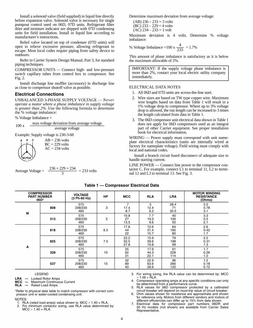
Electrical ConnectionsUNBALANCED 3-PHASE SUPPLY VOLTAGE — Neveroperate a motor where a phase imbalance in supply voltageis greater than 2%. Use the following formula to determinethe % voltage imbalance:% Voltage Imbalance =
Example: Supply voltage is 230-3-60AB = 236 voltsBC = 229 voltsAC = 234 volts
Determine maximum deviation from average voltage:(AB) 236 – 233 = 3 volts(BC) 233 – 229 = 4 volts(AC) 234 – 233 = 1 volt
Maximum deviation is 4 volts. Determine % voltageimbalance:
This amount of phase imbalance is satisfactory as it is belowthe maximum allowable of 2%.
ELECTRICAL DATA NOTES1. All 06D and 07D units are across-the-line start.2. Wire sizes are based on TW type copper wire. Maximum
wire lengths based on data from Table 1 will result in a1% voltage drop to compressor. Where up to 3% voltagedrop is allowed, the run length can be increased to 3 timesthe length calculated from data in Table 1.
3. The 06D compressor unit electrical data shown in Table 1does not apply for 06D compressors used as an integralpart of other Carrier equipment. See proper installationbook for electrical information.
WIRING — Power supply must correspond with unit name-plate electrical characteristics (units are internally wired atfactory for nameplate voltage). Field wiring must comply withlocal and national codes.
Install a branch circuit fused disconnect of adequate size tohandle starting current.LINE POWER — Connect line power to the compressor con-tactor C. For example, connect L1 to terminal 11, L2 to termi-nal 12 and L3 to terminal 13. See Fig. 3.
Table 1 — Compressor Electrical Data
LEGEND
*Refer to physical data table to match compressor with correct com-pressor unit or water-cooled condensing unit.
NOTES:1. RLA (rated load amps) value shown is: MCC ÷ 1.40 = RLA.2. For minimum contactor sizing, use RLA value determined by:
MCC ÷ 1.40 = RLA.
3. For wiring sizing, the RLA value can be determined by: MCC÷ 1.56 = RLA.
4. Compressor operating amps at any specific conditions can onlybe determined from a performance curve.
5. RLA values for 06D compressor protected by a calibratedcircuit breaker will depend on must-trip value of circuit breaker.
6. Ohm values shown for resistance are approximate and shownfor reference only. Motors from different vendors and motors ofdifferent efficiencies can differ up to 15% from data shown.
7. Electrical data for compressor part numbers 06DR and50 Hz models (not shown) are available from Carrier SalesRepresentative.
100 xmax voltage deviation from average voltage
average voltage
Average Voltage =236 + 229 + 234
= 233 volts3
% Voltage Imbalance =100 x4
= 1.7%233
IMPORTANT: If the supply voltage phase imbalance ismore than 2%, contact your local electric utility companyimmediately.
COMPRESSORPART NUMBER
06D*
VOLTAGE(3 Ph-60 Hz) HP MCC RLA LRA
MOTOR WINDINGRESISTANCE
(Ohms)
M
808575
37 5 28.4 5.0
208/230 17.4 12.4 71 0.78460 8.7 6.2 35.5 3.1
313575
510.8 7.7 40 3.3
208/230 27 19.3 100 0.5460 13.5 9.6 50 2.1
A
818575
6.517.6 12.6 64 2.6
208/230 44 31.4 160 0.42460 22 15.7 80 1.7
825575
7.522.2 15.9 79 2.0
208/230 55.5 39.6 198 0.31460 27.8 19.8 99 1.3
328575
1025 17.9 91 1.7
208/230 62 44.3 228 0.26460 31 22.1 114 1.0
537575
1532 22.9 96 1.2
208/230 89 63.6 266 0.18460 40 28.6 120 0.72
LRA — Locked Rotor AmpsMCC — Maximum Continuous CurrentRLA — Rated Load Amps

5
Fig. 3 — Unit Label Diagram — 06D,07D Units
AUX — AuxiliaryC — Compressor ContactorCH — Crankcase HeaterCR — Control RelayDX — Direct ExpansionEQUIP — EquipmentFU — FuseGND — GroundHPS — High-Pressure SwitchIP — Internal ProtectorLLS — Liquid Line Solenoid ValveLPS — Low-Pressure SwitchM3 — Cooling Tower FanNEC — National Electrical CodeOL — OverloadOPS — Oil-Pressure SwitchPOR — Pumpout RelaySW — Start-Stop-Reset Switch
LEGEND
TB — Terminal BlockTM — Timer MotorTR — Timer Relay
Terminal Block Connector
Unmarked Terminal
Marked Terminal
Factory Wiring
Field Control WiringTo indicate common potential only;not to represent wiring.Splice
NOTES:1. Factory wiring is in compliance with NEC. Any field modifications
or additions must be in compliance with all applicable codes. Usecopper, copper-clad aluminum for field power supply only.
2. Field power supply wiring must be 75 C minimum.3. Compressor thermally protected. Three-phase motors are pro-
tected against primary single-phasing condition.4. Pilot duty control must be field supplied. Minimum contact rating
must be 25 va.5. 60 Hz units have 120-volt control circuit. 50 Hz units have
230-volt control circuit. A separate source of supply at the correctvoltage must be field supplied through a fused disconnect device
with a maximum rating of 15 A to TB2 connections (Hot Side) and (Neutral).
6. Open control circuit disconnect switch for servicing only. Discon-nect must remain closed for crankcase heater to operate.
7. A transformer of the following rating may be field supplied for60 Hz units: 350 va.
8. Transformer must be fused and grounded per applicable codes.9. If any of the original wiring furnished must be replaced, it must
be replaced with 90 C wire or its equivalent.
L1L2
6
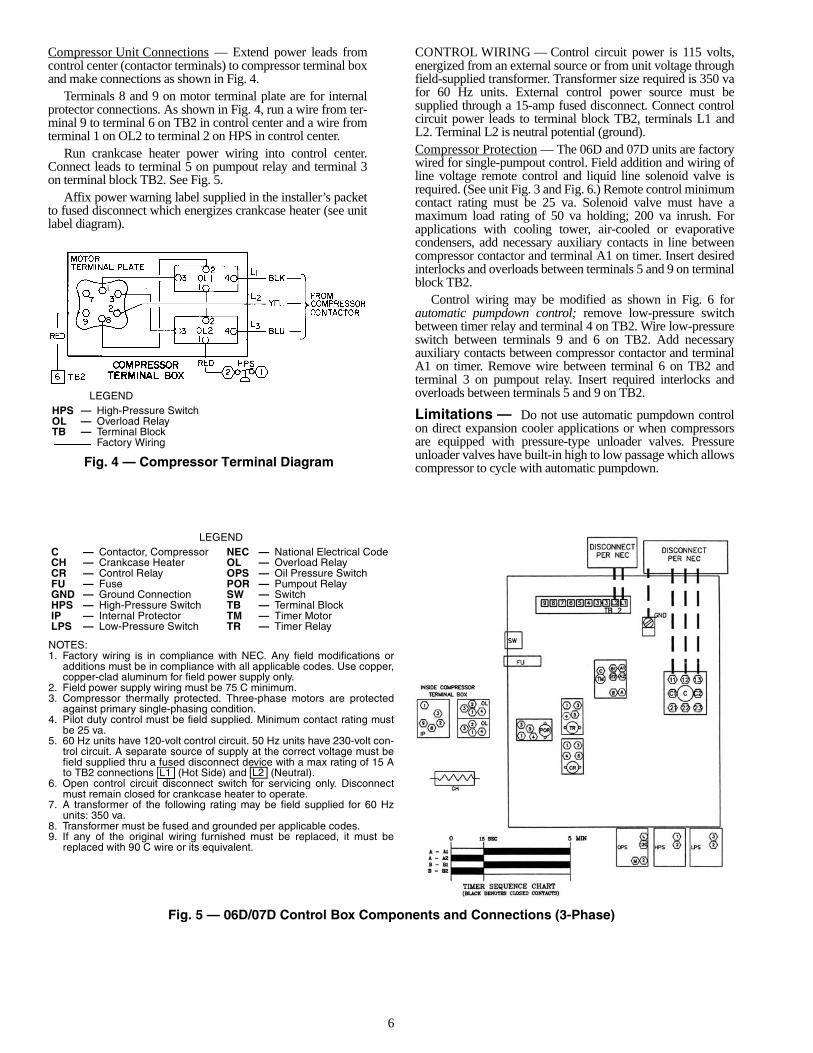
Compressor Unit Connections — Extend power leads fromcontrol center (contactor terminals) to compressor terminal boxand make connections as shown in Fig. 4.
Terminals 8 and 9 on motor terminal plate are for internalprotector connections. As shown in Fig. 4, run a wire from ter-minal 9 to terminal 6 on TB2 in control center and a wire fromterminal 1 on OL2 to terminal 2 on HPS in control center.
Run crankcase heater power wiring into control center.Connect leads to terminal 5 on pumpout relay and terminal 3on terminal block TB2. See Fig. 5.
Affix power warning label supplied in the installer’s packetto fused disconnect which energizes crankcase heater (see unitlabel diagram).
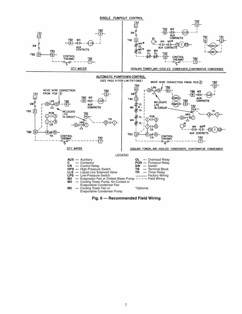
CONTROL WIRING — Control circuit power is 115 volts,energized from an external source or from unit voltage throughfield-supplied transformer. Transformer size required is 350 vafor 60 Hz units. External control power source must besupplied through a 15-amp fused disconnect. Connect controlcircuit power leads to terminal block TB2, terminals L1 andL2. Terminal L2 is neutral potential (ground).Compressor Protection — The 06D and 07D units are factorywired for single-pumpout control. Field addition and wiring ofline voltage remote control and liquid line solenoid valve isrequired. (See unit Fig. 3 and Fig. 6.) Remote control minimumcontact rating must be 25 va. Solenoid valve must have amaximum load rating of 50 va holding; 200 va inrush. Forapplications with cooling tower, air-cooled or evaporativecondensers, add necessary auxiliary contacts in line betweencompressor contactor and terminal A1 on timer. Insert desiredinterlocks and overloads between terminals 5 and 9 on terminalblock TB2.
Control wiring may be modified as shown in Fig. 6 forautomatic pumpdown control; remove low-pressure switchbetween timer relay and terminal 4 on TB2. Wire low-pressureswitch between terminals 9 and 6 on TB2. Add necessaryauxiliary contacts between compressor contactor and terminalA1 on timer. Remove wire between terminal 6 on TB2 andterminal 3 on pumpout relay. Insert required interlocks andoverloads between terminals 5 and 9 on TB2.
Limitations — Do not use automatic pumpdown controlon direct expansion cooler applications or when compressorsare equipped with pressure-type unloader valves. Pressureunloader valves have built-in high to low passage which allowscompressor to cycle with automatic pumpdown.
LEGEND
Fig. 4 — Compressor Terminal Diagram
HPS — High-Pressure SwitchOL — Overload RelayTB — Terminal Block
Factory Wiring
Fig. 5 — 06D/07D Control Box Components and Connections (3-Phase)
LEGEND
NOTES:1. Factory wiring is in compliance with NEC. Any field modifications or
additions must be in compliance with all applicable codes. Use copper,copper-clad aluminum for field power supply only.
2. Field power supply wiring must be 75 C minimum.3. Compressor thermally protected. Three-phase motors are protected
against primary single-phasing condition.4. Pilot duty control must be field supplied. Minimum contact rating must
be 25 va.5. 60 Hz units have 120-volt control circuit. 50 Hz units have 230-volt con-
trol circuit. A separate source of supply at the correct voltage must befield supplied thru a fused disconnect device with a max rating of 15 Ato TB2 connections (Hot Side) and (Neutral).
6. Open control circuit disconnect switch for servicing only. Disconnectmust remain closed for crankcase heater to operate.
7. A transformer of the following rating may be field supplied for 60 Hzunits: 350 va.
8. Transformer must be fused and grounded per applicable codes.9. If any of the original wiring furnished must be replaced, it must be
replaced with 90 C wire or its equivalent.
C — Contactor, Compressor NEC — National Electrical CodeCH — Crankcase Heater OL — Overload RelayCR — Control Relay OPS — Oil Pressure SwitchFU — Fuse POR — Pumpout RelayGND — Ground Connection SW — SwitchHPS — High-Pressure Switch TB — Terminal BlockIP — Internal Protector TM — Timer MotorLPS — Low-Pressure Switch TR — Timer Relay
L1 L2
7
Fig. 6 — Recommended Field Wiring
LEGENDAUX — Auxiliary OL — Overload RelayC — Contactor POR — Pumpout RelayCR — Control Relay SW — SwitchHPS — High-Pressure Switch TB — Terminal BlockLLS — Liquid Line Solenoid Valve TR — Timer RelayLPS — Low-Pressure Switch Factory WiringM3 — Evaporator Fan or Chilled Water Pump Field WiringM4 — Cooling Tower Pump, Air-Cooled or
Evaporative Condenser FanM5 — Cooling Tower Fan or
Evaporative Condenser Pump*Optional.
8
Refrigerant Charging
EVACUATE, DEHYDRATE AND LEAK TEST — Entire re-frigerant system must be evacuated, dehydrated and leak testedby methods described in Carrier Standard Service TechniquesManual, Chapter 1, Sections 1-6 and 1-7. Use sight glass meth-od to charge system. See Section 1-8 of manual for details.CHARGE THE SYSTEM — Charge to a clear sight glasswhile holding saturated condensing pressure constant at 125 F(air-cooled systems) or 105 F (water-cooled systems). Addadditional refrigerant to fill condenser subcooler coils, whereapplicable, for air-cooled applications.06D Compressor Units — See condenser data for additionalcharge required to fill subcooler after clear sight glass isobtained.
INITIAL START-UP
Crankcase heater should be energized a minimum of24 hours before starting unit. Do not permit crankcase heatersto be deenergized during normal shutdown periods.
Check to see that oil level is 1/3 to 2/3 up on compressor sightglass.
Open water supply valve and allow water to reach condens-er. Open pressure line valve of water regulating valve, if used.(Turn condenser fan on when the compressor unit is appliedwith air-cooled condenser.)
Backseat (open) the compressor suction and discharge shut-off valves; open liquid line valve at receiver.
Start evaporator fan or chilled water pump.
To Start Compressor — Close main power switch,control power switch, and unit ON-OFF switch. Time Guard®control circuit causes a short delay before compressor starts.
Recheck oil level and check oil pressure. See Oil Charge fordetails.
With unit operating, voltage at compressor terminals mustbe within limits shown on nameplate. Phases must be balancedwithin 2% of voltage (refer to Electrical Connections section).Contact local power company for correction of improper linevoltage or phase imbalance. Operation of unit on improper linevoltage or with excessive phase imbalance constitutes abuseand is not covered by Carrier Warranty.NOTE: The 06D, 07D unit safety controls are of theautomatic-reset type. If compressor is shut off by a safetycontrol, do not permit control to reset more than once beforedetermining cause of shutdown.
CHECKING OPERATION
Refer to Carrier Standard Service Techniques Manual,Chapter 2 for complete instructions on checking electricalcomponents.
Oil Charge (See Tables 2A and 2B) — Check oillevel in compressor sight glass after 15 to 20 minutes ofoperation. If oil level is low, add oil according to methodsdescribed in Carrier Standard Service Techniques Manual,Chapter 1 (Section 1-11). Add oil through suction manifoldconnection on 4-cylinder compressors, and oil port on6-cylinder compressors.
The preferred method for a complete recharge is to 1/2 sightglass with compressor shut down.
When additional oil, or a complete charge, is required, useonly Carrier-approved compressor oil.Approved* oils are:Witco. . . . . . . . . . . . . . . . . . . . . . . . . . . . . . . . . . . . ..Suniso 3GSTexaco, Inc. . . . . . . . . . . . . . . . . . . . . . . . . . . . . Capella WF-32*Oils approved for R-12, R-22, R-502 Carrier refrigerants.For other refrigerants, contact Carrier Factory SalesRepresentative.
High-Pressure Switch — Check by throttling condens-er water or blocking airflow on air-cooled units, allowing headpressure to rise gradually. Check discharge pressure constantlythroughout procedure. Compressor should shut off within 10 psiof values shown in Table 3.
Low-Pressure Switch — Check by slowly closing suc-tion shutoff valve or by completely closing liquid line shutoffvalve. A decrease of suction pressure will follow. Compressorshould shut off within 4 psi of values shown in Table 3.
Oil Pressure Switch (OPS) — The oil pressure switchprotects against damage from loss of oil or loss of oil pressureduring unit start-up. If the oil pressure differential sensed by theOPS is 6 psig or less on unit start-up, the switch remains closedand the OPS heater is energized.
The switch time delay is approximately 45 seconds. If after45 seconds the oil pressure differential sensed by the OPS isless than 11 psig, the heater remains energized. The OPS tem-perature actuated switch then opens and the compressor isdeenergized. If the differential reaches 11 psig, the OPS opensand deenergizes the heater and the system operates normally.
To restart the unit, push the OPS reset button and then pushthe control circuit switch on the unit control box to OFF andthen to ON.
Time Guard® Control — Control provides a delay ofapproximately 5 minutes before restarting compressor aftershutdown for any reason. On starting, the Time Guard controltimer causes a delay of 15 seconds after thermostat closesbefore compressor will start.
When charging, or when removing charge, circulate waterthrough water-cooled condenser(s) and cooler continuouslyto prevent freezing. Freezing damage is considered abuseand is not covered by Carrier warranty.
Do not attempt start-up with terminal cover removed.Bodily injury or death may result from explosion and/orfire if power is supplied to compressor with the terminalcover removed or unsecured. See warning label on termi-nal cover.
IMPORTANT: Do not reuse drained oil and do not use oilthat has been exposed to atmosphere.
IMPORTANT: If the oil pressure switch causes unit lock-out, determine and correct the cause of the lockout (such asloss of compressor oil or flooded compressor) beforerestarting the unit. Failure to correct the cause of OPS lock-out may constitute abuse. Equipment failure due to abuse isnot covered by warranty.

9
Table 2A — 06D Physical Data
*Compressors listed are for R-22 applications. For R-134a and R-507/404A an 06DR compressor is standard. Factory compressor substitutesmay be made. Contact Carrier Sales Representative.
NOTE: The 06DE8251 compressor unit with the 06DA825 compressorreplaces the 06DE8241 once inventory of the 06DA824 compressor isdepleted.
Table 2B — 07D Physical Data
LEGEND
*Compressor listed is the standard compressor for R-22, air conditioningduty. An 06DR compressor is standard equipment for low temperature(R-507/404A) or medium temperature (R-134a) applications. Factorysubstitutions may be made. Contact Carrier Sales Representative.
†The condenser listed is for R-22, air conditioning duty and may changebased on the application. Maximum condenser operating pressure:350 psi refrigerant side, 300 psi water side (“CX” models); 350 psirefrigerant side, 150 psi water side (“AX” models).
NOTE: The 07DB210 with the 06DA825 compressor replaces the07DB210 with the 06DA824 once the compressor inventory is depleted.
Table 3 — Factory Switch Settings
LEGEND
NOTES:1. Values for the high- and low-pressure switches based on R-22.
For other refrigerants, reset to pressure corresponding to satura-tion temperatures indicated by the listed pressures.
2. Values for oil pressure are above operating suction pressure(pressure differential between suction and discharge pressuresof oil pump).
CAPACITY CONTROL (Suction Cutoff Type)Control Set Point (Cylinder Load Point) — Setpoint is adjustable from 0 to 86 psig. Pressure differentialbetween cylinder load-up point and cylinder unload point isadjustable from 7 to 19 psi.
To Regulate Control Set Point — Refer to Fig. 7.Turn adjustment nut clockwise to its bottom stop (with nut inthis position, set point is 86 psig). Control set point is thenregulated to desired pressure by turning adjustment nut coun-terclockwise. Every full turn decreases set point by 7.2 psi.Approximately 12 turns in counterclockwise direction will de-crease control set point to 0 psig. Table 4 shows steps of controlfor the compressor and condensing unit.
Pressure Differential Adjustment — Turn differ-ential adjusting screw counterclockwise to its back-stop posi-tion (differential in this position is 7 psi). Pressure differential isset by turning adjustment screw clockwise. Every full turnincreases differential by 1.2 psi. Approximately 10 turns inclockwise direction will increase pressure differential to 19 psi.
UNIT 06D A8081 H3131 A8181 E8251 E3281 E5371OPERATING WEIGHT (lb) 180 250 265 325 325 330REFRIGERANT R-134a, R-22, R-507/404ACOMPRESSOR — 06D* M808 M313 A818 A825 A328 A537
Cylinders 2 4 4 6 6 6Bore (in.) 2 2 2 2 2 2Stroke (in.) 11/4 1 17/16 11/4 115/32 115/16Displacement (cfm at 1750 rpm) 8 13 18.3 23.9 28 37.1Maximum Rpm 1750Oil Charge (pt) 3 4.5 5.5 8 8 8High Side Maximum Pressure 450 PSIGLow Side Maximum Pressure 245 PSIG
CONNECTIONS (in.)Suction Valve (ODF) 7/8 7/8 11/8 13/8 13/8 13/8Discharge Valve (ODF) 5/8 5/8 7/8 7/8 7/8 11/8
UNIT 07D A203 B205 A208 B210 B212 B215OPERATING WEIGHT (lb) 270 395 420 545 595 620REFRIGERANT R-134a, R-22, R-507/404ACOMPRESSOR — 06D* M808 M313 A818 A825 A328 A537
Cylinders 2 4 4 6 6 6Bore (in.) 2 2 2 2 2 2Stroke (in.) 11/4 1 17/16 11/4 115/32 115/16Displacement (cfm at 1750 rpm) 8 13 18.3 23.9 28 37.1Maximum Rpm 1750Oil Charge (pt) 3 4.5 5.5 8 8 8High Side Maximum Pressure 450 PSIGLow Side Maximum Pressure 245 PSIG
CONDENSER (Shell and Tube)† Part Number P701-0605CX P701-0607CX P701-0610CX P701-0615CX P701-0620CX P701-0625AX
Refrigerant StorageCapacity (lb)
R-134a 17.20 15.90 24.40 31.60 27.40 39.802.86 3.16 5.00 7.55 8.47 9.18
R-22 17.00 15.70 24.10 31.20 27.10 39.30
Min Refrigerant OperatingCharge (lb)
2.80 3.10 4.90 7.40 8.30 9.00
R-507/404A 14.70 13.60 20.90 27.10 23.50 34.102.80 3.10 4.90 7.40 8.30 9.00
REFRIGERANT CONNECTION (in. ODF) Inlet 15/8 15/8 15/8 15/8 15/8 15/8 Outlet 11/8 11/8 11/8 11/8 11/8 11/8WATER CONNECTION (in. FPT) Inlet/Outlet 1 1 11/4 11/4 11/4 2
FPT — Female Pipe ThreadODF — Outside Diameter, Female
SWITCH TYPEPRESSURE CHANGE AFFECTING
SWITCH POSITIONClosed Open
High Pressure 210 (±10) (psig) 290 (±10) (psig)Low Pressure 70 (±4) (psig) 60 (±4) (psig)Oil Pressure 6 (psid) 11 (psid)
psid — pounds per square inch differentialpsig — pounds per square inch gage
802
→
→

10
Table 4 — Capacity Control Reduction Steps
Capacity Control Pressure (Fig. 8)LOADED OPERATION — Pressure-operated control valveis controlled by suction pressure and actuated by dischargepressure. Each valve controls 2 cylinders (one bank). Onstart-up, controlled cylinders do not load up until differentialbetween suction and discharge pressures is approximately25 psi.
When suction pressure rises high enough to overcomecontrol set point spring, the diaphragm snaps to the left andrelieves pressure against the poppet valve. The drive spring
moves the poppet valve to left and it seats in the closedposition.
With poppet valve closed, discharge gas is directed into theunloader-piston chamber and pressure builds up against thepiston. When pressure against unloader piston is high enoughto overcome the unloader valve spring, piston moves valve tothe right, opening suction port. Suction gas can now be drawninto the cylinders and the bank is running fully loaded.UNLOADED OPERATION — As suction pressure dropsbelow set point, control spring expands, snapping diaphragm toright. This forces poppet valve open and allows gas fromdischarge manifold to vent through base of control valve tosuction side. Loss of full discharge pressure against unloadedpiston allows unloader valve spring to move valve left toclosed position. The suction port is blocked, isolating thecylinder bank from the suction manifold. The cylinder bank isnow unloaded.
CONDENSER MAINTENANCE
To inspect and clean condenser, drain water and removecondenser heads. To drain condenser, shut off water supply anddisconnect inlet and outlet piping. Remove drain plugs andvent plug.
With condenser heads removed, inspect tubes for refrigerantleaks. (Refer to Carrier Refrigerant Service Techniques Manual.)
Clean condenser tubes with nylon brush (available fromCarrier Service Department). Flush water through tubes whilecleaning. If hard scale has formed, clean tubes chemically. Donot use brushes that will scrape or scratch tubes.
Because the condenser water circuit is usually an opensystem, the condenser tubes may be subject to contaminationby foreign matter. Local water conditions may cause excessivefouling or pitting of tubes. Condenser tubes, therefore, shouldbe cleaned at least once a year or more often if the water iscontaminated.
Proper water treatment can minimize tube fouling andpitting. If such conditions are anticipated, water treatmentanalysis is recommended. Refer to the Carrier System DesignManual, Part 5, for general water conditioning information.
If hard scale has formed, clean the tubes chemically. Con-sult an experienced and reliable water-treatment firm in yourarea for treatment recommendations. Clean the condenser bygravity or by forced circulation as shown in Fig. 9 and 10.
UNIT 06D,07DNO. OF CONTR
CYL
% Full Load Capacity100 67 49 32
% Full Load kW100 73 57 46Number of Active Cylinders
ALL 4 CYLINDER MODELS 2 4 — 2 —
ALL 6 CYLINDER MODELS 4 6 4 — 2
IMPORTANT: If the ambient temperature is below 32 Fduring a shutdown period; protect the condenser fromfreezing by draining the water from the system or by add-ing antifreeze to the water.
BYPASS PISTON-USEDWITH HOT GAS BYPASSTYPE OF UNLOADING ONLY.NOT REQUIRED WITHSUCTION CUTOFF TYPEUNLOADING.
DIFFERENTIAL SCREWSEALING CAP (CAP MUSTBE REPLACED TO PREVENTREFRIGERANT LEAKAGE)
BYPASSPISTON RING
PRESSUREDIFFERENTIALADJUSTMENTSCREW
POWERHEAD
VALVE BODY
CONTROLSET POINTADJUSTMENTNUT
Fig. 7 — Capacity Control Valve(Pressure Type)

11
LEGEND
Fig. 11 — Compressor(Bottom Plate Removed)
1 — Oil Pressure Relief Valve 5 — Eccentric Shaft2 — Piston and Eccentric
Strap Assembly6 — Eccentric Strap Side
Shield3 — Motor End Counterweight 7 — Oil Suction Tube4 — Oil Return Check Valve 8 — Pump End Counterweight
FILL CONDENSER WITHCLEANING SOLUTION. DONOT ADD SOLUTIONMORE RAPIDLY THANVENT CAN EXHAUSTGASES CAUSED BYCHEMICAL ACTION.
CONDENSER
3’ TO 4’
VENTPIPE
5’ APPROX
1”PIPE SUCTION
PUMPSUPPORT
TANK
FINE MESHSCREEN
RETURN
GAS VENT
PUMPPRIMINGCONN. GLOBE
VALVES
1” PIPE
CONDENSER
REMOVE WATERREGULATING VALVE
CENTRIFUGAL PUMP 1/2 HP30 GPM AT 35’ HEAD
CLOSE VENT PIPEVALVE WHENPUMP ISRUNNING
Fig. 8 — Capacity Control Valve Operation
Fig. 9 — Gravity Circulation Fig. 10 — Forced Circulation
12
SERVICE
Service Notes1. Where compressor components are shown, they are in
normal order of removal from compressor.2. For replacement items, use Carrier specified parts.
See Carrier 06D Specified Parts list for compressor partinterchangeability.
3. Before compressor is opened, the refrigerant must beremoved from it by the Pumpdown method.a. Start compressor, close suction shutoff valve, and
reduce crankcase pressure to 2 psig (bypass lowpressurestat with jumper).
b. Stop compressor and isolate from system byclosing discharge shutoff valve.
c. Bleed any residual refrigerant. Drain oil ifnecessary.
4. After disassembly, clean all parts with solvent. Usemineral spirits, white gasoline or naphtha.
5. Before assembly, coat all parts with compressor oil andclean and inspect all gasket surfaces. Replace all gasketswith new standard specified gaskets, coated withcompressor oil. See Table 5 for typical torque values.
6. After reassembly, evacuate compressor and open suctionand discharge valves. Restart compressor and adjustrefrigerant charge.
Table 5 — Torque Values
LEGENDNEF — National Extra Fine
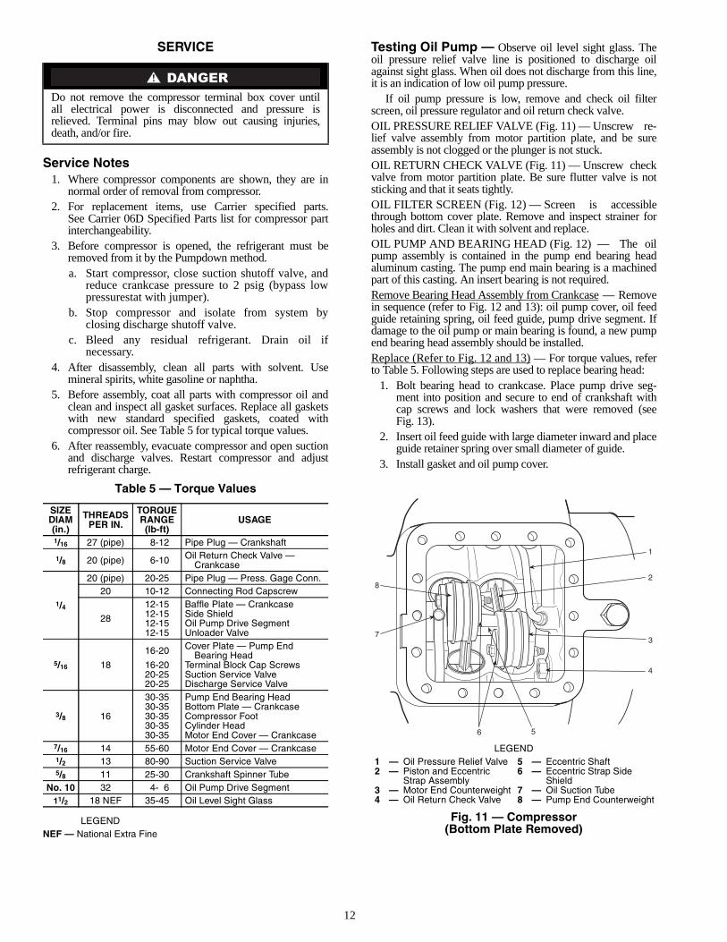
Testing Oil Pump — Observe oil level sight glass. Theoil pressure relief valve line is positioned to discharge oilagainst sight glass. When oil does not discharge from this line,it is an indication of low oil pump pressure.
If oil pump pressure is low, remove and check oil filterscreen, oil pressure regulator and oil return check valve.OIL PRESSURE RELIEF VALVE (Fig. 11) — Unscrew re-lief valve assembly from motor partition plate, and be sureassembly is not clogged or the plunger is not stuck.OIL RETURN CHECK VALVE (Fig. 11) — Unscrew checkvalve from motor partition plate. Be sure flutter valve is notsticking and that it seats tightly.OIL FILTER SCREEN (Fig. 12) — Screen is accessiblethrough bottom cover plate. Remove and inspect strainer forholes and dirt. Clean it with solvent and replace.OIL PUMP AND BEARING HEAD (Fig. 12) — The oilpump assembly is contained in the pump end bearing headaluminum casting. The pump end main bearing is a machinedpart of this casting. An insert bearing is not required.Remove Bearing Head Assembly from Crankcase — Removein sequence (refer to Fig. 12 and 13): oil pump cover, oil feedguide retaining spring, oil feed guide, pump drive segment. Ifdamage to the oil pump or main bearing is found, a new pumpend bearing head assembly should be installed.Replace (Refer to Fig. 12 and 13) — For torque values, referto Table 5. Following steps are used to replace bearing head:
1. Bolt bearing head to crankcase. Place pump drive seg-ment into position and secure to end of crankshaft withcap screws and lock washers that were removed (seeFig. 13).
2. Insert oil feed guide with large diameter inward and placeguide retainer spring over small diameter of guide.
3. Install gasket and oil pump cover.
Do not remove the compressor terminal box cover untilall electrical power is disconnected and pressure isrelieved. Terminal pins may blow out causing injuries,death, and/or fire.
SIZEDIAM(in.)
THREADSPER IN.
TORQUERANGE(lb-ft)
USAGE
1/16 27 (pipe) 8-12 Pipe Plug — Crankshaft
1/8 20 (pipe) 6-10 Oil Return Check Valve —Crankcase
1/4
20 (pipe) 20-25 Pipe Plug — Press. Gage Conn.20 10-12 Connecting Rod Capscrew
28
12-15 Baffle Plate — Crankcase12-15 Side Shield12-15 Oil Pump Drive Segment12-15 Unloader Valve
5/16 18
16-20 Cover Plate — Pump EndBearing Head
16-20 Terminal Block Cap Screws20-25 Suction Service Valve20-25 Discharge Service Valve
3/8 16
30-35 Pump End Bearing Head30-35 Bottom Plate — Crankcase30-35 Compressor Foot30-35 Cylinder Head30-35 Motor End Cover — Crankcase
7/16 14 55-60 Motor End Cover — Crankcase1/2 13 80-90 Suction Service Valve5/8 11 25-30 Crankshaft Spinner Tube
No. 10 32 4- 6 Oil Pump Drive Segment11/2 18 NEF 35-45 Oil Level Sight Glass
8
7
1
2
3
4
56
LEGEND
Fig. 11 — Compressor(Bottom Plate Removed)
1 — Oil Pressure Relief Valve 5 — Eccentric Shaft2 — Piston and Eccentric
Strap Assembly6 — Eccentric Strap Side
Shield3 — Motor End Counterweight 7 — Oil Suction Tube4 — Oil Return Check Valve 8 — Pump End Counterweight

13
PHASE BARRIERPOSITIONINGKEY (SEE FIG. 19)
8 7 6 5 4 3 26 2
2120191817161514
13
12
11
9
10
1
25
24
23
22
44 42 41 16 38 37 36 35
4645 47 48 49 2715
394043 34 33 32 31 30
29
28
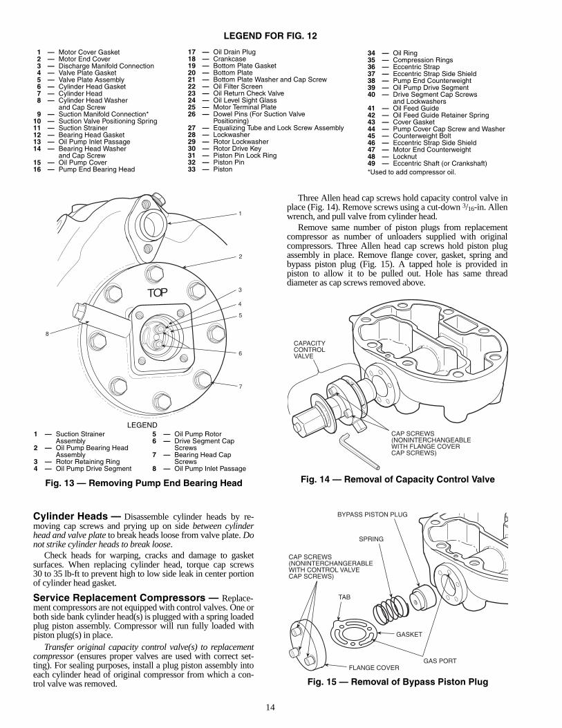
Fig. 12 — 06D Compressor Components (4-Cylinder with Eccentric Shaft Shown)
14
LEGEND FOR FIG. 12
Cylinder Heads — Disassemble cylinder heads by re-moving cap screws and prying up on side between cylinderhead and valve plate to break heads loose from valve plate. Donot strike cylinder heads to break loose.
Check heads for warping, cracks and damage to gasketsurfaces. When replacing cylinder head, torque cap screws30 to 35 lb-ft to prevent high to low side leak in center portionof cylinder head gasket.
Service Replacement Compressors — Replace-ment compressors are not equipped with control valves. One orboth side bank cylinder head(s) is plugged with a spring loadedplug piston assembly. Compressor will run fully loaded withpiston plug(s) in place.
Transfer original capacity control valve(s) to replacementcompressor (ensures proper valves are used with correct set-ting). For sealing purposes, install a plug piston assembly intoeach cylinder head of original compressor from which a con-trol valve was removed.
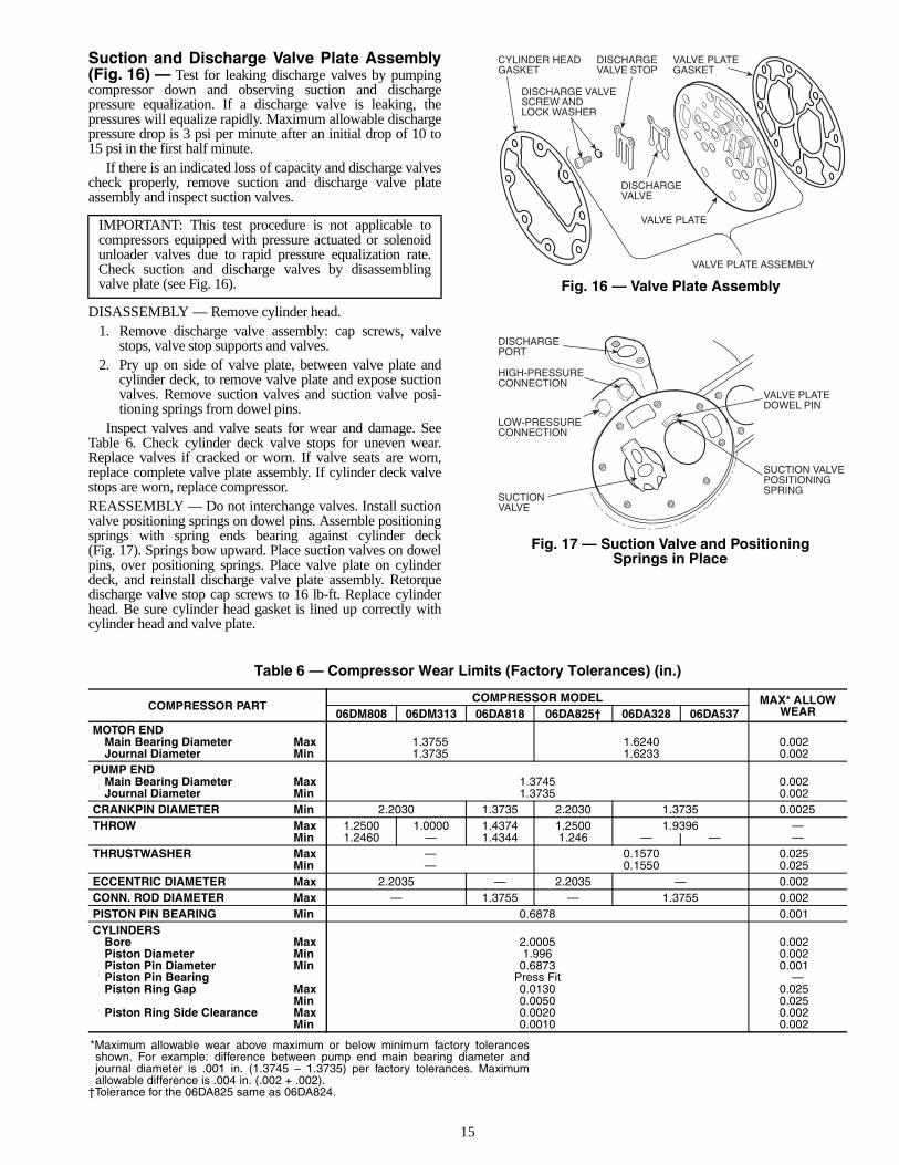
Three Allen head cap screws hold capacity control valve inplace (Fig. 14). Remove screws using a cut-down 3/16-in. Allenwrench, and pull valve from cylinder head.
Remove same number of piston plugs from replacementcompressor as number of unloaders supplied with originalcompressors. Three Allen head cap screws hold piston plugassembly in place. Remove flange cover, gasket, spring andbypass piston plug (Fig. 15). A tapped hole is provided inpiston to allow it to be pulled out. Hole has same threaddiameter as cap screws removed above.
TOP
8
1
2
3
4
5
6
7
LEGEND1 — Suction Strainer
Assembly2 — Oil Pump Bearing Head
Assembly3 — Rotor Retaining Ring4 — Oil Pump Drive Segment
5 — Oil Pump Rotor6 — Drive Segment Cap
Screws7 — Bearing Head Cap
Screws8 — Oil Pump Inlet Passage
Fig. 13 — Removing Pump End Bearing Head
CAPACITYCONTROLVALVE
CAP SCREWS(NONINTERCHANGEABLEWITH FLANGE COVERCAP SCREWS)
BYPASS PISTON PLUG
SPRING
TAB
FLANGE COVER
CAP SCREWS(NONINTERCHANGERABLEWITH CONTROL VALVECAP SCREWS)
GASKET
GAS PORT
Fig. 14 — Removal of Capacity Control Valve
Fig. 15 — Removal of Bypass Piston Plug
1 — Motor Cover Gasket2 — Motor End Cover3 — Discharge Manifold Connection4 — Valve Plate Gasket5 — Valve Plate Assembly6 — Cylinder Head Gasket7 — Cylinder Head8 — Cylinder Head Washer
and Cap Screw9 — Suction Manifold Connection*
10 — Suction Valve Positioning Spring11 — Suction Strainer12 — Bearing Head Gasket13 — Oil Pump Inlet Passage14 — Bearing Head Washer
and Cap Screw15 — Oil Pump Cover16 — Pump End Bearing Head
17 — Oil Drain Plug18 — Crankcase19 — Bottom Plate Gasket20 — Bottom Plate21 — Bottom Plate Washer and Cap Screw22 — Oil Filter Screen23 — Oil Return Check Valve24 — Oil Level Sight Glass25 — Motor Terminal Plate26 — Dowel Pins (For Suction Valve
Positioning)27 — Equalizing Tube and Lock Screw Assembly28 — Lockwasher29 — Rotor Lockwasher30 — Rotor Drive Key31 — Piston Pin Lock Ring32 — Piston Pin33 — Piston
34 — Oil Ring35 — Compression Rings36 — Eccentric Strap37 — Eccentric Strap Side Shield38 — Pump End Counterweight39 — Oil Pump Drive Segment40 — Drive Segment Cap Screws
and Lockwashers41 — Oil Feed Guide42 — Oil Feed Guide Retainer Spring43 — Cover Gasket44 — Pump Cover Cap Screw and Washer45 — Counterweight Bolt46 — Eccentric Strap Side Shield47 — Motor End Counterweight48 — Locknut49 — Eccentric Shaft (or Crankshaft)*Used to add compressor oil.
15
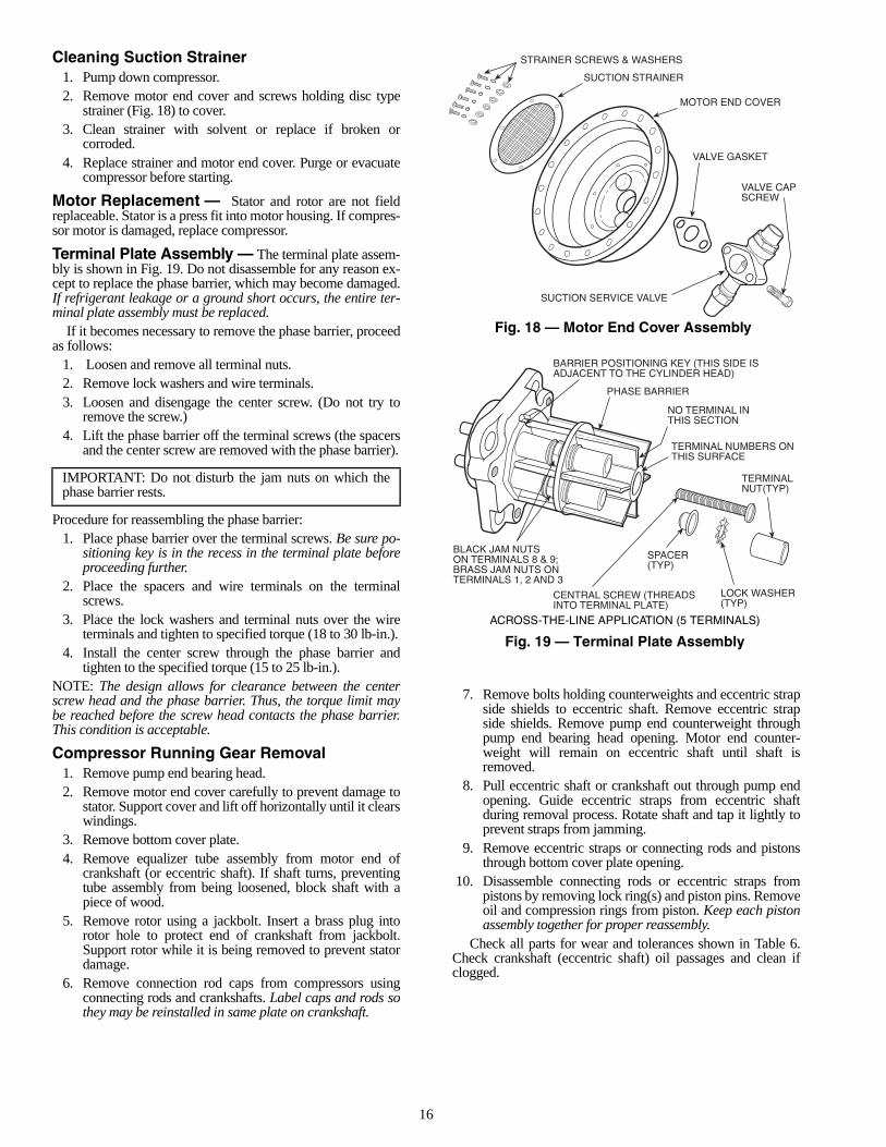
Suction and Discharge Valve Plate Assembly(Fig. 16) — Test for leaking discharge valves by pumpingcompressor down and observing suction and dischargepressure equalization. If a discharge valve is leaking, thepressures will equalize rapidly. Maximum allowable dischargepressure drop is 3 psi per minute after an initial drop of 10 to15 psi in the first half minute.
If there is an indicated loss of capacity and discharge valvescheck properly, remove suction and discharge valve plateassembly and inspect suction valves.
DISASSEMBLY — Remove cylinder head.1. Remove discharge valve assembly: cap screws, valve
stops, valve stop supports and valves.2. Pry up on side of valve plate, between valve plate and
cylinder deck, to remove valve plate and expose suctionvalves. Remove suction valves and suction valve posi-tioning springs from dowel pins.
Inspect valves and valve seats for wear and damage. SeeTable 6. Check cylinder deck valve stops for uneven wear.Replace valves if cracked or worn. If valve seats are worn,replace complete valve plate assembly. If cylinder deck valvestops are worn, replace compressor.REASSEMBLY — Do not interchange valves. Install suctionvalve positioning springs on dowel pins. Assemble positioningsprings with spring ends bearing against cylinder deck(Fig. 17). Springs bow upward. Place suction valves on dowelpins, over positioning springs. Place valve plate on cylinderdeck, and reinstall discharge valve plate assembly. Retorquedischarge valve stop cap screws to 16 lb-ft. Replace cylinderhead. Be sure cylinder head gasket is lined up correctly withcylinder head and valve plate.
Table 6 — Compressor Wear Limits (Factory Tolerances) (in.)
*Maximum allowable wear above maximum or below minimum factory tolerancesshown. For example: difference between pump end main bearing diameter andjournal diameter is .001 in. (1.3745 – 1.3735) per factory tolerances. Maximumallowable difference is .004 in. (.002 + .002).
†Tolerance for the 06DA825 same as 06DA824.
IMPORTANT: This test procedure is not applicable tocompressors equipped with pressure actuated or solenoidunloader valves due to rapid pressure equalization rate.Check suction and discharge valves by disassemblingvalve plate (see Fig. 16).
COMPRESSOR PARTCOMPRESSOR MODEL MAX* ALLOW
WEAR06DM808 06DM313 06DA818 06DA825† 06DA328 06DA537MOTOR END
Main Bearing Diameter Max 1.3755 1.6240 0.002Journal Diameter Min 1.3735 1.6233 0.002
PUMP ENDMain Bearing Diameter Max 1.3745 0.002Journal Diameter Min 1.3735 0.002
CRANKPIN DIAMETER Min 2.2030 1.3735 2.2030 1.3735 0.0025THROW Max 1.2500 1.0000 1.4374 1.2500 1.9396 —
Min 1.2460 — 1.4344 1.246 — — —THRUSTWASHER Max — 0.1570 0.025
Min — 0.1550 0.025ECCENTRIC DIAMETER Max 2.2035 — 2.2035 — 0.002CONN. ROD DIAMETER Max — 1.3755 — 1.3755 0.002PISTON PIN BEARING Min 0.6878 0.001CYLINDERS
Bore Max 2.0005 0.002Piston Diameter Min 1.996 0.002Piston Pin Diameter Min 0.6873 0.001Piston Pin Bearing Press Fit —Piston Ring Gap Max 0.0130 0.025
Min 0.0050 0.025Piston Ring Side Clearance Max 0.0020 0.002
Min 0.0010 0.002
CYLINDER HEADGASKET
VALVE PLATEGASKET
DISCHARGE VALVESCREW ANDLOCK WASHER
DISCHARGEVALVE
VALVE PLATE
VALVE PLATE ASSEMBLY
DISCHARGEVALVE STOP
DISCHARGEPORT
HIGH-PRESSURECONNECTION
LOW-PRESSURECONNECTION
SUCTIONVALVE
VALVE PLATEDOWEL PIN
SUCTION VALVEPOSITIONINGSPRING
Fig. 16 — Valve Plate Assembly
Fig. 17 — Suction Valve and PositioningSprings in Place
16
Cleaning Suction Strainer1. Pump down compressor.2. Remove motor end cover and screws holding disc type
strainer (Fig. 18) to cover.3. Clean strainer with solvent or replace if broken or
corroded.4. Replace strainer and motor end cover. Purge or evacuate
compressor before starting.
Motor Replacement — Stator and rotor are not fieldreplaceable. Stator is a press fit into motor housing. If compres-sor motor is damaged, replace compressor.
Terminal Plate Assembly — The terminal plate assem-bly is shown in Fig. 19. Do not disassemble for any reason ex-cept to replace the phase barrier, which may become damaged.If refrigerant leakage or a ground short occurs, the entire ter-minal plate assembly must be replaced.
If it becomes necessary to remove the phase barrier, proceedas follows:
1. Loosen and remove all terminal nuts.2. Remove lock washers and wire terminals.3. Loosen and disengage the center screw. (Do not try to
remove the screw.)4. Lift the phase barrier off the terminal screws (the spacers
and the center screw are removed with the phase barrier).
Procedure for reassembling the phase barrier:1. Place phase barrier over the terminal screws. Be sure po-
sitioning key is in the recess in the terminal plate beforeproceeding further.
2. Place the spacers and wire terminals on the terminalscrews.
3. Place the lock washers and terminal nuts over the wireterminals and tighten to specified torque (18 to 30 lb-in.).
4. Install the center screw through the phase barrier andtighten to the specified torque (15 to 25 lb-in.).
NOTE: The design allows for clearance between the centerscrew head and the phase barrier. Thus, the torque limit maybe reached before the screw head contacts the phase barrier.This condition is acceptable.
Compressor Running Gear Removal1. Remove pump end bearing head.2. Remove motor end cover carefully to prevent damage to
stator. Support cover and lift off horizontally until it clearswindings.
3. Remove bottom cover plate.4. Remove equalizer tube assembly from motor end of
crankshaft (or eccentric shaft). If shaft turns, preventingtube assembly from being loosened, block shaft with apiece of wood.
5. Remove rotor using a jackbolt. Insert a brass plug intorotor hole to protect end of crankshaft from jackbolt.Support rotor while it is being removed to prevent statordamage.
6. Remove connection rod caps from compressors usingconnecting rods and crankshafts. Label caps and rods sothey may be reinstalled in same plate on crankshaft.
7. Remove bolts holding counterweights and eccentric strapside shields to eccentric shaft. Remove eccentric strapside shields. Remove pump end counterweight throughpump end bearing head opening. Motor end counter-weight will remain on eccentric shaft until shaft isremoved.
8. Pull eccentric shaft or crankshaft out through pump endopening. Guide eccentric straps from eccentric shaftduring removal process. Rotate shaft and tap it lightly toprevent straps from jamming.
9. Remove eccentric straps or connecting rods and pistonsthrough bottom cover plate opening.
10. Disassemble connecting rods or eccentric straps frompistons by removing lock ring(s) and piston pins. Removeoil and compression rings from piston. Keep each pistonassembly together for proper reassembly.
Check all parts for wear and tolerances shown in Table 6.Check crankshaft (eccentric shaft) oil passages and clean ifclogged.
IMPORTANT: Do not disturb the jam nuts on which thephase barrier rests.
STRAINER SCREWS & WASHERS
SUCTION STRAINER
MOTOR END COVER
VALVE GASKET
SUCTION SERVICE VALVE
VALVE CAPSCREW
BARRIER POSITIONING KEY (THIS SIDE ISADJACENT TO THE CYLINDER HEAD)
PHASE BARRIER
NO TERMINAL INTHIS SECTION
TERMINAL NUMBERS ONTHIS SURFACE
TERMINALNUT(TYP)
LOCK WASHER(TYP)
BLACK JAM NUTSON TERMINALS 8 & 9;BRASS JAM NUTS ONTERMINALS 1, 2 AND 3
CENTRAL SCREW (THREADSINTO TERMINAL PLATE)
SPACER(TYP)
Fig. 18 — Motor End Cover Assembly
ACROSS-THE-LINE APPLICATION (5 TERMINALS)
Fig. 19 — Terminal Plate Assembly
17
PUMP END MAIN BEARING — This bearing is a ma-chined part of the new aluminum oil pump and bearing headcasting. Disassemble bearing head. If bearing is scored orworn, replace complete bearing head.CRANKCASE AND MOTOR END MAIN BEAR-INGS — These bearings are not field replaceable. If bearingsare worn or damaged, replace compressor.
Compressor Running Gear ReplacementCRANKSHAFT — Install crankshaft through pump end,carefully guiding it through main bearings. Replace rotor.Attach equalizer tube assembly to motor end of shaft.
Eccentric shafts must be installed after piston assemblies.Place motor end counterweight on shaft before inserting shaftinto compressor. See Piston Assembly Replacement.PISTON ASSEMBLY — Attach connecting rods or eccentricstraps to pistons with piston pins and lock in place with pistonpin lock rings. Place lock rings with gap on the side.They should be tight enough so they cannot be rotated byfinger pressure.RINGS
1. Check ring gap by inserting each ring separately incylinder, approximately 3/8 in. from top. Ring gap shouldbe between .013 and .005 inch.
2. Install compression rings in top piston grooves with sidemarked “Top” toward piston head. Install oil ring belowcompression ring with notched end on bottom. Staggerring gaps around piston.
3. Measure side clearance between ring and piston(Table 6). Check for free action.
PISTON ASSEMBLY REPLACEMENTCompressors Using Crankshafts — Install connecting rodand piston assemblies into cylinders. Place chamfered sides ofconnecting rods against radius of crankpins. Install connectingrod caps to matching connecting rods through bottom of crank-case. Be sure chamfered sides of caps are against radius ofcrankpins. Caps are locked in place with cap screws. Use 8 to10 lb-ft to tighten cap screws.Compressors Using Eccentric Shafts — Install eccentricstrap and piston assemblies into cylinders. Install eccentricshaft through pump end, carefully guiding it througheccentric straps and main bearings. Install pump end counter-weight to eccentric shaft and replace eccentric strap sideshields.
Turn crankshaft or eccentric shaft to be sure there is nobinding between bearing surfaces and journals. Replace oilscreen, bottom cover plate, valve plates and cylinder heads.
COMPRESSOR MOTOR BURNOUT
Clean-Up Procedure — If a hermetic motor burns out,the stator winding decomposes, forming carbon, water and acidwhich contaminate refrigerant systems. Remove these contam-inants from system to prevent repeat motor failures.
1. Close compressor suction and discharge service valves,and bleed refrigerant from compressor. Save remainingrefrigerant in system.
2. Check control box for welded contactor contacts, weldedoverload contacts or burned out heater elements. Checkterminal plate for burned or damaged terminals, insula-tion, and shorted or grounded terminals. Repair or replacewhere necessary.
3. Remove suction and discharge shutoff valve bolts and allother connections to damaged compressor. Removedamaged compressor and replace with new compressor.Replace liquid line filter drier with a drier of one sizelarger.
4. Purge new compressor. Triple-evacuate, using the follow-ing procedure:a. Evacuate to 5000 microns.b. Break vacuum with system refrigerant. Pressurize
to 15 psig. Wait 20 minutes to remove moisture.c. Re-evacuate to 5000 microns.d. Repeat Step b.e. Evacuate to 1000 microns or below if possible.
5. Place compressor in operation. After 2 to 4 hours ofoperation, check compressor oil for signs of discolorationand/or acidity. If oil shows signs of contamination,replace oil charge, filter driers, and clean suction strainerwith solvent. Repeat this procedure until oil stays cleanand acid free for 48 hours of operation.
Do not attempt start-up with terminal cover removed.Bodily injury or death may result from explosion and/orfire if power is supplied to compressor with the terminalcover removed or unsecured. See warning label on termi-nal cover.
18
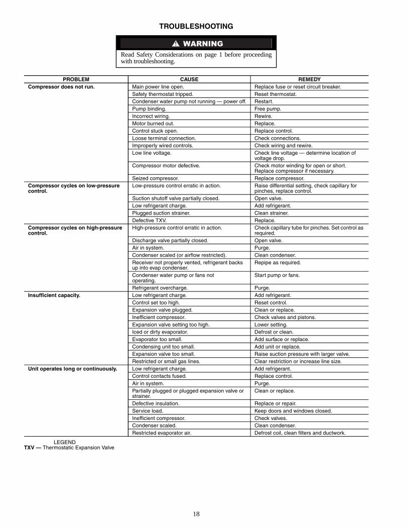
TROUBLESHOOTING
LEGENDTXV — Thermostatic Expansion Valve
Read Safety Considerations on page 1 before proceedingwith troubleshooting.
PROBLEM CAUSE REMEDYCompressor does not run. Main power line open. Replace fuse or reset circuit breaker.
Safety thermostat tripped. Reset thermostat.Condenser water pump not running — power off. Restart.Pump binding. Free pump.Incorrect wiring. Rewire.Motor burned out. Replace.Control stuck open. Replace control.Loose terminal connection. Check connections.Improperly wired controls. Check wiring and rewire.Low line voltage. Check line voltage — determine location of
voltage drop.Compressor motor defective. Check motor winding for open or short.
Replace compressor if necessary.Seized compressor. Replace compressor.
Compressor cycles on low-pressure control.
Low-pressure control erratic in action. Raise differential setting, check capillary for pinches, replace control.
Suction shutoff valve partially closed. Open valve.Low refrigerant charge. Add refrigerant.Plugged suction strainer. Clean strainer.Defective TXV. Replace.
Compressor cycles on high-pressure control.
High-pressure control erratic in action. Check capillary tube for pinches. Set control as required.
Discharge valve partially closed. Open valve.Air in system. Purge.Condenser scaled (or airflow restricted). Clean condenser.Receiver not properly vented, refrigerant backs up into evap condenser.
Repipe as required.
Condenser water pump or fans not operating.
Start pump or fans.
Refrigerant overcharge. Purge.Insufficient capacity. Low refrigerant charge. Add refrigerant.
Control set too high. Reset control.Expansion valve plugged. Clean or replace.Inefficient compressor. Check valves and pistons.Expansion valve setting too high. Lower setting.Iced or dirty evaporator. Defrost or clean.Evaporator too small. Add surface or replace.Condensing unit too small. Add unit or replace.Expansion valve too small. Raise suction pressure with larger valve.Restricted or small gas lines. Clear restriction or increase line size.
Unit operates long or continuously. Low refrigerant charge. Add refrigerant.Control contacts fused. Replace control.Air in system. Purge.Partially plugged or plugged expansion valve or strainer.
Clean or replace.
Defective insulation. Replace or repair.Service load. Keep doors and windows closed.Inefficient compressor. Check valves.Condenser scaled. Clean condenser.Restricted evaporator air. Defrost coil, clean filters and ductwork.
19
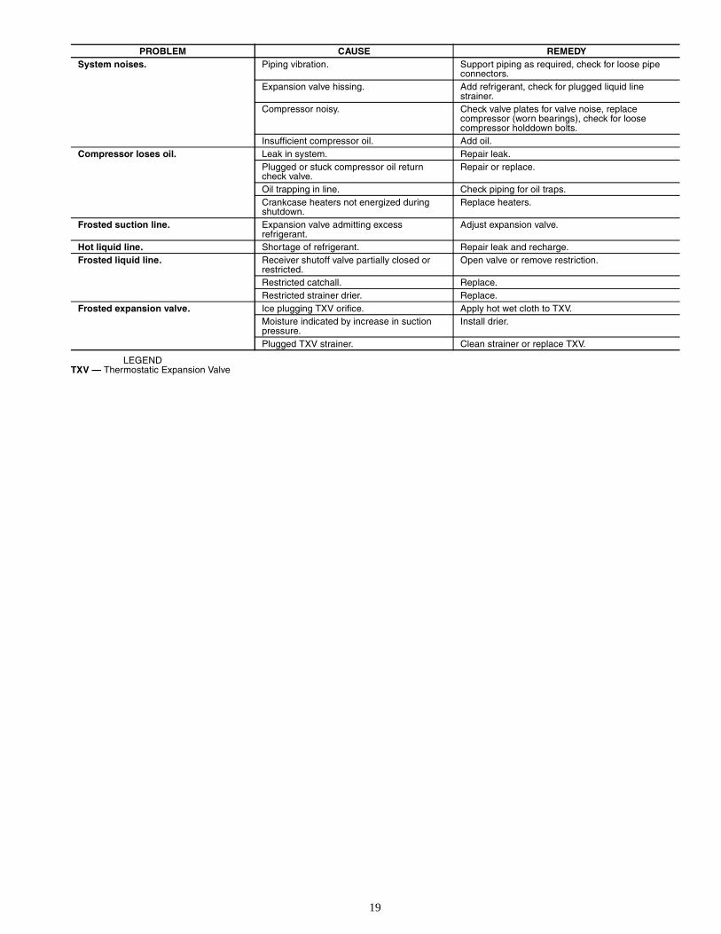
LEGENDTXV — Thermostatic Expansion Valve
PROBLEM CAUSE REMEDYSystem noises. Piping vibration. Support piping as required, check for loose pipe
connectors.Expansion valve hissing. Add refrigerant, check for plugged liquid line
strainer.Compressor noisy. Check valve plates for valve noise, replace
compressor (worn bearings), check for loose compressor holddown bolts.
Insufficient compressor oil. Add oil.Compressor loses oil. Leak in system. Repair leak.
Plugged or stuck compressor oil return check valve.
Repair or replace.
Oil trapping in line. Check piping for oil traps.Crankcase heaters not energized during shutdown.
Replace heaters.
Frosted suction line. Expansion valve admitting excess refrigerant.
Adjust expansion valve.
Hot liquid line. Shortage of refrigerant. Repair leak and recharge.Frosted liquid line. Receiver shutoff valve partially closed or
restricted.Open valve or remove restriction.
Restricted catchall. Replace.Restricted strainer drier. Replace.
Frosted expansion valve. Ice plugging TXV orifice. Apply hot wet cloth to TXV.Moisture indicated by increase in suction pressure.
Install drier.
Plugged TXV strainer. Clean strainer or replace TXV.

Manufacturer reserves the right to discontinue, or change at any time, specifications or designs without notice and without incurring obligations.PC 802 Catalog No. 530-608 Printed in U.S.A. Form 06/07D-3SI Pg 20 802 7-02 Replaces: 06/07D-2SIBook 2 2 4 4
Tab 1b 2a 2b 3a
Copyright 2002 Carrier Corporation