Installation & Set Up Guide - Cooke Industries€¦ · Installation & Set Up Guide A fully...
12
Installation & Set Up Guide A fully automated pool and spa water leveling System Full Electrical Certification Inside & outside use (V99086) C-Tick Approval N11116
Transcript of Installation & Set Up Guide - Cooke Industries€¦ · Installation & Set Up Guide A fully...
Installation & Set Up Guide A fully automated pool and spa water leveling System
Full Electrical Certification
Inside & outside use
(V99086)
C-Tick Approval
N11116
Index
Page 1: Three Main Components
Page 2: Diagrams 3, 4, 5, 6
Page 3: Installation Guide
Page 4-5: Sensor & Solenoid Connections
Page 6: Initial Set Up- testing of water witch
Page 7: Setting the sensor
Page 8: Operating Mode (Dip Switch Settings)
Page 9: Internal Block Diagram Of control
Back Page: Contact Information
Danger! This unit is powered by a 240Volt AC supply which could
cause serious injury or death.
ALWAYS SWITCH OFF AND REMOVE THE POWER LEAD
FROM THE POWER SUPPLY PRIOR TO OPENING
CONTROL BOX LID.
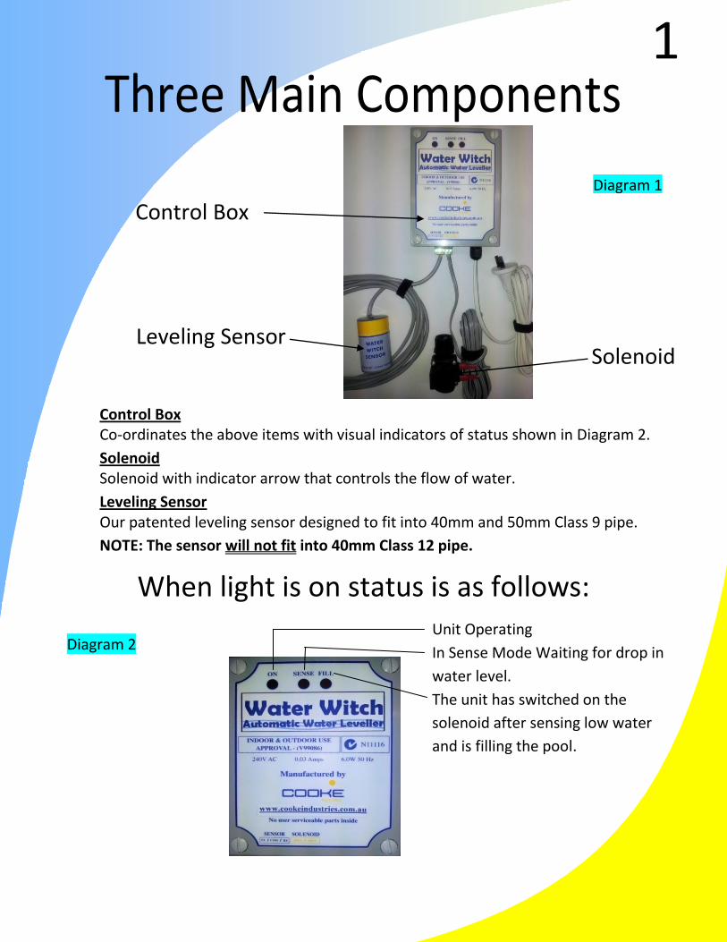
Three Main Components
Connecting your business to the technology resources you need
Control Box
Solenoid Leveling Sensor
Control Box
Co-ordinates the above items with visual indicators of status shown in Diagram 2.
Solenoid Solenoid with indicator arrow that controls the flow of water.
Leveling Sensor Our patented leveling sensor designed to fit into 40mm and 50mm Class 9 pipe.
NOTE: The sensor will not fit into 40mm Class 12 pipe.
When light is on status is as follows: Unit Operating
In Sense Mode Waiting for drop in
water level.
The unit has switched on the
solenoid after sensing low water
and is filling the pool.
Diagram 1
Diagram 2
1
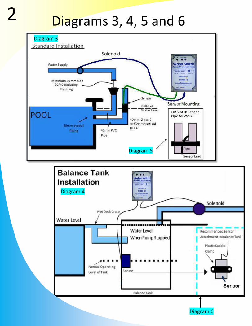
Diagram 3
Diagrams 3, 4, 5 and 6
Diagram 5
Diagram 6
Diagram 4
6
2

Important These pipes must remain below the water level by a
minimum of 200mm (more is better) until elbowed into
the vertical position.
A minimum vertical height of 300mm above the top of
the pool is required for both pipes.
Control Box Mount the control box at least 1.2 meters off the ground using the
steel bracket provided.
Solenoid The solenoid must be installed in the water supply line using the
flow direction arrow indicated on the solenoid body.
Sensor Refer to the diagrams 5 & 6 on the opposite page for mounting of
the sensor
The suggested method of plumbing is two 40mm class 9PVC pipes plumbed
through the pool wall and returned to the pump and filter area.
These pipes are placed approximately 300mm below normal water level and
finished off in the pool with push in eyeballs to match the other pool fittings. The
pipes are usually run along the suction and return trench and elbowed up near the
pool equipment.
Installation Guide
POOL INSTALLERS
Sensor Pipe & Fill Plumbing
3
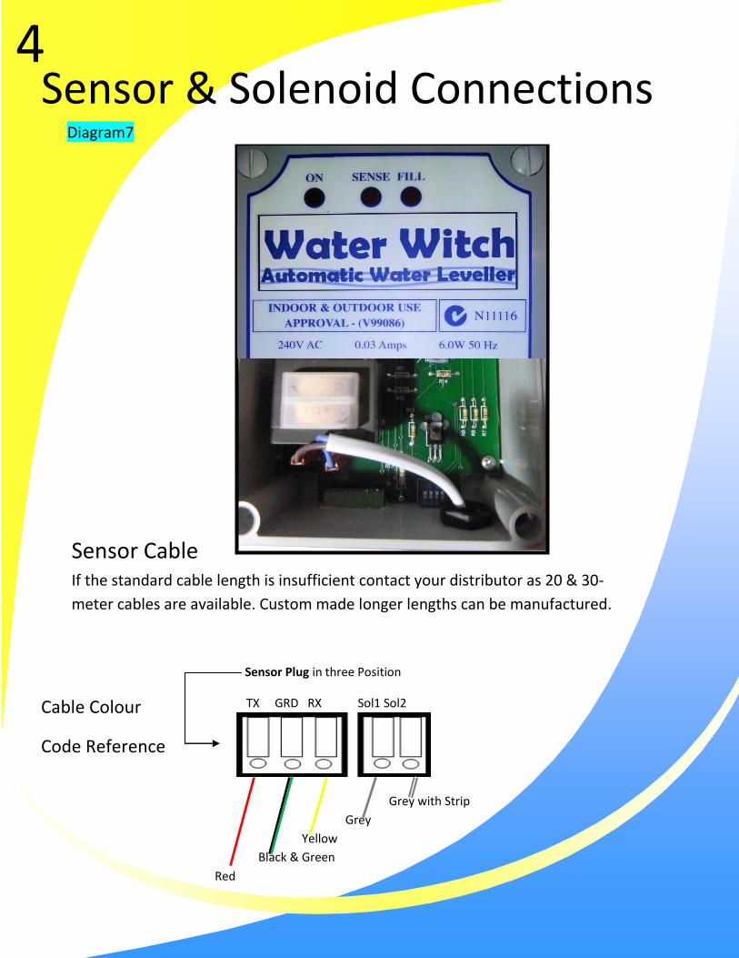
Sensor Cable If the standard cable length is insufficient contact your distributor as 20 & 30-
meter cables are available. Custom made longer lengths can be manufactured.
Sensor & Solenoid Connections
TX GRD RX Sol1 Sol2 Cable Colour
Code Reference
Diagram7
Sensor Plug in three Position
4
Grey with Strip
Grey
Yellow
Black & Green
Red
The Water Witch is designed to be installed
close to the pool equipment. Both the sensor
and solenoid leads are normally 5 meters long
with plugs attached for connections to the base
of the control box as shown in Diagram 7 (Water
Witch 20 & 30 for the balance tank installs come
with a 20 or 30 meter Sensor lead respectively).
DO NOT CUT OR JOIN
THE CABLE.
THIS WILL VOID
WARRANTY
5

Sensor & Solenoid Connections Page 5
Initial Set Up
Step by step Guide
Once the Water Witch has been mounted properly, TESTING OF THE WATER WITCH is required. To ensure that the sensor and solenoid are working properly, please complete the following steps: Step 1: Ensure the pool is filled to the operating water
level required. Step 2: Connect the sensor and solenoid plugs to the
control box ensuring that the plugs are connected as indicated on the label on the control box (sensor left; solenoid right).
Step 3: Turn power and water supplies on. The ON light will automatically come on and begin to flash. Depending on what position the sensor is in, will determine if the sense light is on and flashing or the fill light is on.
Step 4: Holding the sensor upside down, check that the ON & SENSE lights are flashing approximately every two seconds.
Step 5: Turn the sensor the right way up and the ON light will continue to flash and the FILL light will come on. This will turn the water on to fill the pool.
IF THE WATER DOES COME ON, YOU HAVE CORRECTLY INSTALLED THE WATER WITCH SYSTEM.
PLEASE FOLLOW STEPS 6 TO 9 TO SET THE SENSOR.
6
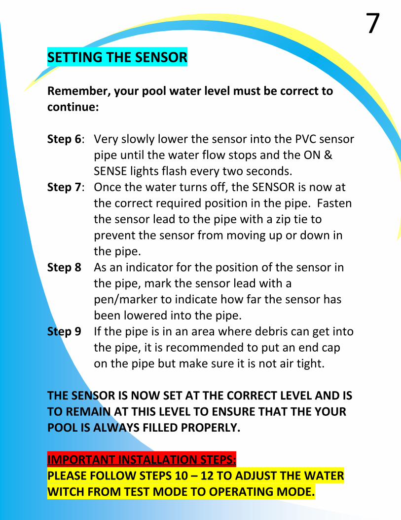
SETTING THE SENSOR Remember, your pool water level must be correct to continue: Step 6: Very slowly lower the sensor into the PVC sensor
pipe until the water flow stops and the ON & SENSE lights flash every two seconds.
Step 7: Once the water turns off, the SENSOR is now at the correct required position in the pipe. Fasten the sensor lead to the pipe with a zip tie to prevent the sensor from moving up or down in the pipe.
Step 8 As an indicator for the position of the sensor in the pipe, mark the sensor lead with a pen/marker to indicate how far the sensor has been lowered into the pipe.
Step 9 If the pipe is in an area where debris can get into the pipe, it is recommended to put an end cap on the pipe but make sure it is not air tight.
THE SENSOR IS NOW SET AT THE CORRECT LEVEL AND IS TO REMAIN AT THIS LEVEL TO ENSURE THAT THE YOUR POOL IS ALWAYS FILLED PROPERLY. IMPORTANT INSTALLATION STEPS: PLEASE FOLLOW STEPS 10 – 12 TO ADJUST THE WATER WITCH FROM TEST MODE TO OPERATING MODE.
7
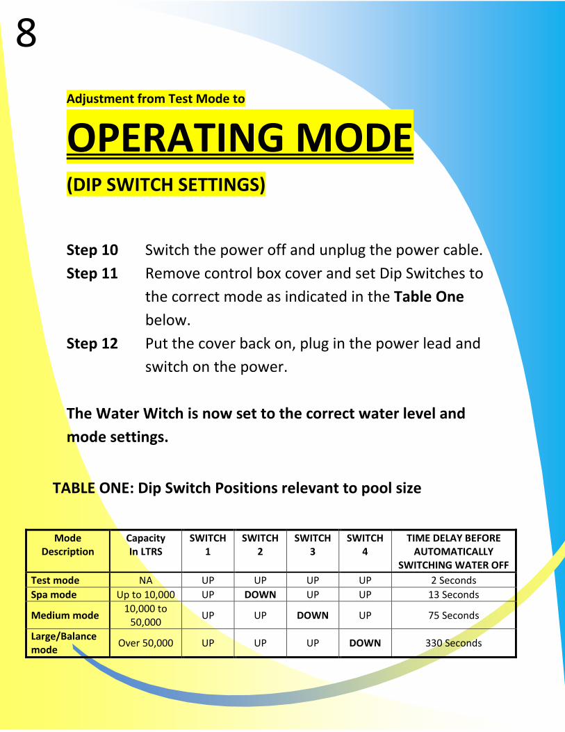
Adjustment from Test Mode to
OPERATING MODE
(DIP SWITCH SETTINGS)
Step 10 Switch the power off and unplug the power cable.
Step 11 Remove control box cover and set Dip Switches to
the correct mode as indicated in the Table One
below.
Step 12 Put the cover back on, plug in the power lead and
switch on the power.
The Water Witch is now set to the correct water level and
mode settings.
TABLE ONE: Dip Switch Positions relevant to pool size
8
Mode Description
Capacity In LTRS
SWITCH 1
SWITCH 2
SWITCH 3
SWITCH 4
TIME DELAY BEFORE AUTOMATICALLY
SWITCHING WATER OFF
Test mode NA UP UP UP UP 2 Seconds
Spa mode Up to 10,000 UP DOWN UP UP 13 Seconds
Medium mode 10,000 to
50,000 UP UP DOWN UP 75 Seconds
Large/Balance mode
Over 50,000 UP UP UP DOWN 330 Seconds
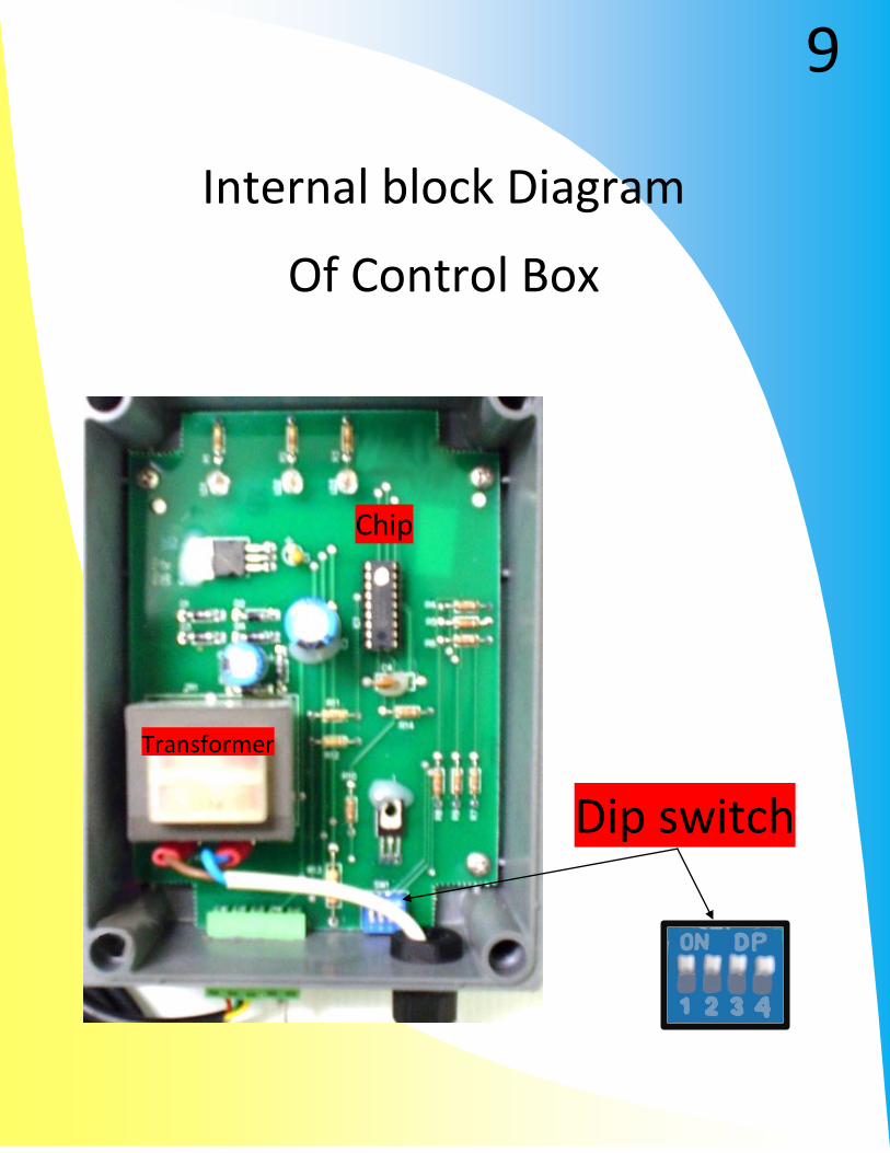
Chip
Dip switch
Transformer
Internal block Diagram
Of Control Box
9

Cooke Industries
p: 1300 652 076
f: (03) 5023 5339
www.cookeindustries.com.au
If you have any questions or
have encountered a problem,
please refer to our website,
www.cookeindustries.com.au
for troubleshooting and
technical support.
Alternatively, call our friendly
staff on 1300 652 076.
Thank you for purchasing