INSTALLATION PROGRAMMING MANUAL · SenSonic transducers ensuring a reliable measurement in narrow...
52
INSTALLATION and PROGRAMMING MANUAL 1 st edition Manufacturer: NIVELCO Process Control Co. H-1043 Budapest, Dugonics u. 11. Tel.: (36-1)-369-7575 Fax: (36-1)-369-8585 e-mail:[email protected] http://www.nivelco.com
Transcript of INSTALLATION PROGRAMMING MANUAL · SenSonic transducers ensuring a reliable measurement in narrow...

INSTALLATIONand
PROGRAMMING MANUAL1st edition
Manufacturer:NIVELCO Process Control Co.H-1043 Budapest, Dugonics u. 11.
Tel.: (36-1)-369-7575 Fax: (36-1)-369-8585e-mail:[email protected] http://www.nivelco.com

BASIC CONCEPTS AND ELEMENTS OF THE ULTRASONIC MEASUREMENT
Programmedmeasurementrange of theapplication
P06Far end blocking
DIST= distance (measured)
Close end blocking (programmed value
LEV= level calculated; P04 - DIST)VOL= volume (calculated from DIST LEV)
Max
mea
surin
g dis
tanc
e of t
he ap
plica
tion (
H)
Max m
easu
ring
dista
nce
of th
e dev
iceDE
FAUL
T va
lue o
f P04
X M
Max
mea
sure
men
t ran
ge o
f the d
evice
Min
meas
uring
dist
ance
(d
ead b
and)
DEFA
ULT
value
of P
05pr
ogra
mmed
value
of P
04
X m

CONTENTS1. INTRODUCTION.............................................................................................................................................................................................................................. 12. ORDER CODES............................................................................................................................................................................................................................... 23. TECHNICAL DATA.......................................................................................................................................................................................................................... 3
3.1 Accessories ............................................................................................................................................................................................................................... 64. INSTALLATION ............................................................................................................................................................................................................................... 7
4.1 Liquid Level Measurement ........................................................................................................................................................................................................ 74.2 Open Channel Flow Measurement............................................................................................................................................................................................ 94.3 Electrical Connection................................................................................................................................................................................................................. 94.4 Loop Curent Checking............................................................................................................................................................................................................... 9
5. PROGRAMMING ........................................................................................................................................................................................................................... 105.1 Programming without Display Module..................................................................................................................................................................................... 115.2 Programming with the SAP-200 Display Module .................................................................................................................................................................... 14
5.2.1 SAP-200 Display Module ................................................................................................................................................................................................ 155.2.2 Steps of the SAP-200 Display Module............................................................................................................................................................................ 155.2.3 Indications of the SAP-200 and LED Status ................................................................................................................................................................... 165.2.4 QUICKSET...................................................................................................................................................................................................................... 175.2.5 Full Parameter Access.................................................................................................................................................................................................... 19
6. PARAMETERS – DESCRIPTIONS AND PROGRAMMING......................................................................................................................................................... 216.1 Measurement Configuration .................................................................................................................................................................................................... 216.2 Current Output......................................................................................................................................................................................................................... 276.3 Measurement Optimisation...................................................................................................................................................................................................... 286.4 Volume Measurement ............................................................................................................................................................................................................. 326.5 Volume Flow Measuring.......................................................................................................................................................................................................... 336.6 32-Point Linearisation.............................................................................................................................................................................................................. 396.7 Informational Parameters (Read Out Parameters).................................................................................................................................................................. 406.8 Additional Parameters of the Flow Metering ........................................................................................................................................................................... 426.9 Test Parameters ...................................................................................................................................................................................................................... 426.10 Simulation.............................................................................................................................................................................................................................. 436.11 Access Lock .......................................................................................................................................................................................................................... 43
7. ERROR CODES............................................................................................................................................................................................................................. 448. PARAMETER TABLE.................................................................................................................................................................................................................... 459. SOUND VELOCITIES IN DIFFERENT GASES ............................................................................................................................................................................ 47

SE/SG-300 series two-wire compact ultrasonic level transmitters 1
Thank you for choosing a NIVELCO instrument.We are sure that you will be satisfied throughout its use.
1. INTRODUCTIONA Total beam angle of 5°-7° at –3 dB as is featured by most of Nivelco’sSenSonic transducers ensuring a reliable measurement in narrow silos withuneven side walls as well as in process tanks with various protrudingobjects. Furthermore, as a result of the narrow beam angle - the emittedultrasonic signals have an outstanding focusing - deep penetration throughgases, vapour and foam is ensured.
rrD
X D
1 m 0,21 m 2 m 0,3 m
5 m 0,56 m
10 m 1 m
15m 1,45 m
X
The Diameterscorresponding to5° beam angle.
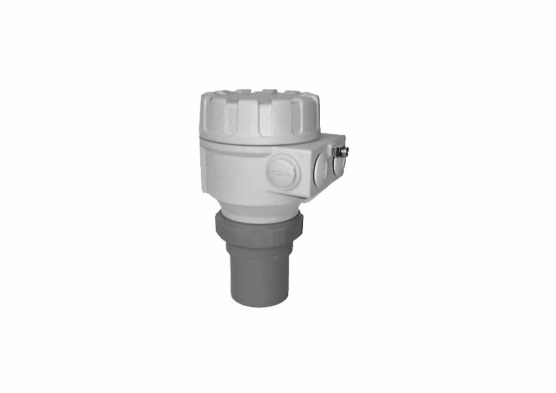
ApplicationThe EchoTREK compact ultrasonic level transmitters from NIVELCO are anexcellent tool for the level measurement of liquids.Level measurement technology based on the non-contacting ultrasonicprinciple is especially suited for applications where, for any reason, nophysical contact can be established to the surface of the material to bemeasured.Such reasons may include corrosive attack by the process medium againstthe measuring device material (acids), possible contamination (sewage) orparticles of the process medium adhering to the measuring device(adhesive materials).
Principle of OperationThe ultrasonic level metering technology is based on the principle ofmeasuring the time required for the ultrasound pulses to make a round tripfrom the sensor to the level to be measured and back. The sensor emits anultrasonic pulse train and receives the echoes reflected. The intelligentelectronic device processes the received signal by selecting the echoreflected by the surface and calculates from the time of flight the distancebetween the sensor and the surface which constitutes the basis of all outputsignals of the EchoTREK
Dead Band is a feature common to all ultrasonic level meters.It is specified as “Minimum measuring distance” in the Technical DataTable. Measurement within this range can not be interpreted.
Minimum measuring distance (Xm) is determined by the design of the unit within which the measuremnt is not possible (Dead Zone). This distance can beextended by programming in order to avoid disturbing effects of possible disturbing echos coming from fixed objects. (Close-end Blocking).
Maximum measuring distance (XM) is the greatest distance (determined by the design of the unit) which can be measured by the unit under idealconditions. The maximum measuring distance of the actual application (H) must not be greater than XM.

2 SE/SG-300 series two-wire compact ultrasonic level transmitters
2. ORDER CODESNote: not all combinations are possible
EchoTREK S - 3 -
TYPE CODE TRANSDUCER /HOUSING CODE MEASURING
RANGE * CODE MOUBTING CODE SUPPLY / OUTPUT CODE
Transmitter E PP/Aluminium A 12; 15 m 4 BSP thread * 0 4 … 20 mA / 12 … 36 VDC 2PVDF/Aluminium B 7; 10 m 6 NPT thread N 4 … 20 mA + HART / 12 … 36 VDC 4Transmitter with
local indicator G PTFE/Aluminium T 6; 8 m 7 DN 80 PN 16 / PP 2SS316Ti/Aluminium S 12; 15 m 8 DN 100 PN 16 / PP 3PP/Plastic P 3; 4 m 9 DN 125 PN 16 / PP 4PVDF/Plastic V DN 150 PN 16 / PP 5PTFE/Plastic F DN 200 PN 16 / PP 6SS316Ti/Plastic M 200 mm bracket K
500 mm bracket L700 mm bracket M
* Measuring range depends on the material of the transducer
SE/SG-300 series two-wire compact ultrasonic level transmitters 3
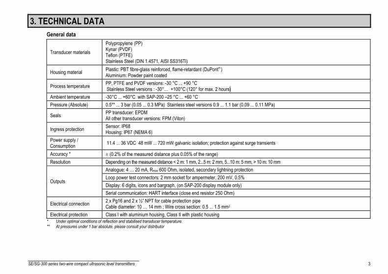
3. TECHNICAL DATAGeneral data
Transducer materialsPolypropylene (PP)Kynar (PVDF)Teflon (PTFE)Stainless Steel (DIN 1.4571, AISI SS316Ti)
Housing material Plastic: PBT fibre-glass reinforced, flame-retardant (DuPont)Aluminium: Powder paint coated
Process temperature PP, PTFE and PVDF versions: -30 °C ... +90 °C Stainless Steel versions : -30°… +100°C (120° for max. 2 hours)
Ambient temperature -30°C ... +60°C with SAP-200 –25 °C ... +60 °CPressure (Absolute) 0.5** ... 3 bar (0.05 ... 0.3 MPa) Stainless steel versions 0.9 ... 1.1 bar (0.09 ... 0.11 MPa)
Seals PP transducer: EPDMAll other transducer versions: FPM (Viton)
Ingress protection Sensor: IP68Housing: IP67 (NEMA 6)
Power supply /Consumption 11.4 ... 36 VDC 48 mW ... 720 mW galvanic isolation; protection against surge transients
Accuracy * ± (0.2% of the measured distance plus 0.05% of the range)Resolution Depending on the measured distance < 2 m: 1 mm, 2...5 m: 2 mm, 5...10 m: 5 mm, > 10 m: 10 mm
Analogue: 4 … 20 mA, Rmax 600 Ohm, isolated, secondary lightning protectionLoop power test connectors: 2 mm socket for ampermeter, 200 mV, 0.5%Display: 6 digits, icons and bargraph, (on SAP-200 display module only)
Outputs
Serial communication: HART interface (close end resistor 250 Ohm)
Electrical connection 2 x Pg16 and 2 x ½” NPT for cable protection pipeCable diameter: 10 … 14 mm ; Wire cross section: 0.5 ... 1.5 mm2
Electrical protection Class I with aluminium housing, Class II with plastic housing* Under optimal conditions of reflection and stabilised transducer temperature.** At pressures under 1 bar absolute, please consult your distributor

4 SE/SG-300 series two-wire compact ultrasonic level transmitters
Special data of the two-wire EchoTREK with PP and PVDF transducers
Type SE -39 -SG -39 -
SE -38 -SG -38 -
SE -37 -SG -37 -
SE -36 -SG -36 -
SE -34 -SG -34 -
Transducer material PP or PVDF PP or PVDF PP or PVDF PP or PVDF PP or PVDFMaximum measuringdistance * [m / ft] 4 6 8 10 15
Min. measuring distance*(Dead band) [m / ft] 0.2 0.25 0.35 0.35 0.45
Total beam angle (-3 dB) 6° 5° 7° 5° 5°Measurement frequency 80 kHz 80 kHz 50 kHz 60 kHz 40 kHzProcess connection 1 ½” thread 2” thread 2” thread Flange Flange
* (from the transducer face)
Special data of the two-wire EchoTREK PTFE and Stainless Steel transducers
Type SE -39 -SG -39 -
SE -38 -SG -38 -
SE -37 -SB -37 -
SE -36 -SG -36 -
SE -34 -SG -34 -
Transducer material PTFE PTFE PTFE St. St. St. St.Maximum measuringdistance * [m/ft] 3 5 6 7 12
Min. measuring distance*(Dead band) [m/ft] 0.2 0.25 0.35 0.4 0.55
Total beam angle (-3 dB) 6° 5° 7° 5° 5°Measurement frequency 80 kHz 80 kHz 50 kHz 60 kHz 40 kHzProcess connection 1 ½” thread 2” thread 2” thread Flange Flange
* (from transducer face)
SAP-200 Display ModuleField indication 6 digits Custom LCD, icons and bargraph,Ambient temperature -25°C … +60°CHousing material PBT fibre-glass reinforced plastic, (DuPont)

SE/SG-300 series two-wire compact ultrasonic level transmitters 5
Dimensions of the two-wire EchoTREKEchoTREK S -39 - / PP, PVDF, PTFE EchoTREK S -3 8- / PP, PVDF, PTFE EchoTREK S -37 - / PP, PVDF, PTFE
BSP length 15NPT 22length
or NPT
2 x NP1/2" T
~89
2 x Pg16
1 1/2" BSP~60
97,5
BSP 15length NPT 22length
or NPT 2" BSP
~89
~60
2 x NP1/2" T
2 x Pg16
97,5 97
,5
~80 or NPT
2" BSP
2 x NP1/2" T
2 x Pg16
BSP 15length NPT 22length
EchoTREK S -36 - / PP, PVDF EchoTREK S -34 - / PP, PVDF
19
74
JIS 10K 80A
DIN DN80 PN16ANSI 3" 150 psi
~30
97,5
~89
2 x NPT1/2"
2 x Pg16
*122
JIS 10K 125AANSI 5" 150 psiDIN DN125 PN16
19
~43
2 x NPT1/2"
~89
2 x Pg16 97,5
*
* Min required flange size

6 SE/SG-300 series two-wire compact ultrasonic level transmitters
EchoTREK S S-36 - / SS316 Ti
ANSI 3" 150 psiDIN DN80 PN16
20,5
~89
2 x Pg16
2 x NPT 1/2"
97,5
~147
EchoTREK S S-34 - / SS316 Ti~89
2 x Pg16
2 x NPT 1/2"
97,5
~157
ANSI 5" 150 psiDIN DN125 PN16
25
Cover
DisplayModule
Electronics
Enclosure
Transducer
3.1 Accessories− Warranty sheet — 2 x Pg16 cable gland− Installation and Programming Manual — SAP-200 Display Module (option)

SE/SG-300 series two-wire compact ultrasonic level transmitters 7
4. INSTALLATION
4.1 Liquid Level Measurement
POSITIONThe optimal position of the EchoTREK is on the radiusr = (0.3 … 0.5) R of the (cylindrical) tank / silo.(Take also sonic cone on page 1 into consideration.)
SENSOR ALIGNMENTThe sensor face has to be parallel tothe surface of the liquid within ± 2-3°.
TEMPERATUREMake sure that the transmitter willbe protected against overheating bydirect sunshine. Sunshade

8 SE/SG-300 series two-wire compact ultrasonic level transmitters
STAND-OFF PIPEThe structure of the stand off pipe should be rigid; the inner rim where the ultrasonic beamleaves the pipe should be rounded.
DminL S - 39 S - 38 S - 37 150 50 60 60200 50 60 75250 65 65 90300 80 75 105350 95 85 120
OBSTACLESMake sure that no in-flow path or objects(e.g. cooling pipes, ladders, bracingmembers, thermometers, etc.) or no tankwall of the ragged surface protrude intothe sensing cone of the ultrasonic beam.One fix object in the tank / silo thatdisturb the measurement can be blockedout by the appropriate programming ofthe EchoTREK
L Ø D
r
DminL S - 36 S - 34 90 80 *
200 80 *350 85 *500 90 *
FOAM
Foaming of the liquid surface may render ultrasonic levelmetering impossible. If possible, a location should be found,where foaming is the least (device should be located as far aspossible from liquid inflow) or a stilling pipe or well should beused.
r
Ø DL
* For values contact your distributor
DminLS S – 36 S S – 34
320 80 -440 - 125
WINDIntensive air (gas) movements in the vicinity of the ultrasoniccone is to be avoided. A strong draft of wind may "blow away"the ultrasound.Devices with lower measuring frequency (40, 20 kHz) arerecommended. L Ø D
r
FUMES/VAPOURSFor closed tanks containing chemicals or other liquids, which creats fume/gases above the liquid surface especially for outdoor tanks exposed to the sun, astrong reduction of the nominal measuring range of the ultrasonic device is to be considered during device selection.Devices with lower measuring frequency (40, 20 kHz) are recommended in these cases units.
SE/SG-300 series two-wire compact ultrasonic level transmitters 9
4.2 Open Channe l Flow Measurement• For ultimate accuracy, install the sensor as close as possible above the expected maximum water level (see minimum measuring range).• Install the device in a place defined by the characteristics of the metering channel along the longitudinal axis of the flume or weir. In case of Parshall
flumes supplied by NIVELCO the location of the sensor is marked.• In some cases foam may develop on the surface. Make sure that the surface, opposite to the sensor remain free of foam for proper sound reflection.• From the point of view of measurement accuracy the length of the channel sections preceding and following the measuring flume and their method of
joining to the measuring channel section are of critical importance.• Despite of the most careful installation, the accuracy of flow metering will be lower than that of specified for the distance measurement. It will be
determined by the features of the flume or weir applied.
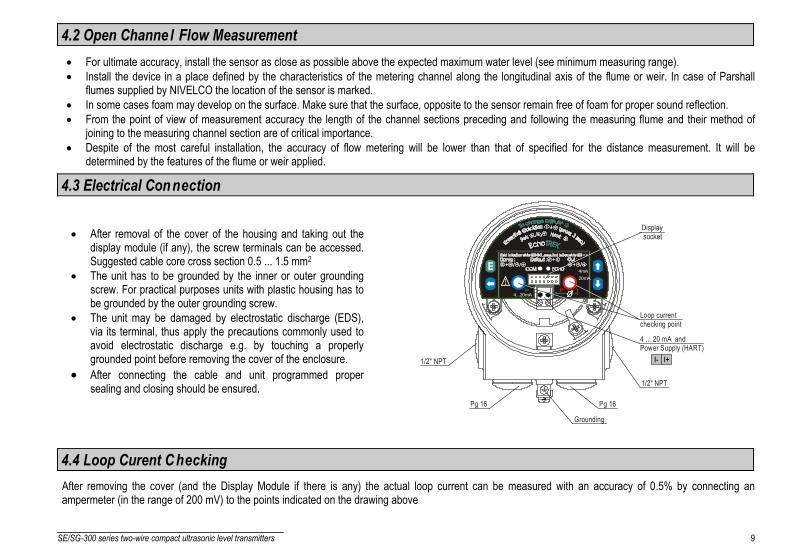
4.3 Electrical Connection
• After removal of the cover of the housing and taking out thedisplay module (if any), the screw terminals can be accessed.Suggested cable core cross section 0.5 ... 1.5 mm2
• The unit has to be grounded by the inner or outer groundingscrew. For practical purposes units with plastic housing has tobe grounded by the outer grounding screw.
• The unit may be damaged by electrostatic discharge (EDS),via its terminal, thus apply the precautions commonly used toavoid electrostatic discharge e.g. by touching a properlygrounded point before removing the cover of the enclosure.
• After connecting the cable and unit programmed propersealing and closing should be ensured.
4...20mA
Loop current checking point
4 ... 20 mA (HART)
and Power Supply
1/2" NPT
I- I+
Pg 16 Pg 16
1/2" NPT
Grounding
20mA4mA
4.4 Loop Curent CheckingAfter removing the cover (and the Display Module if there is any) the actual loop current can be measured with an accuracy of 0.5% by connecting anampermeter (in the range of 200 mV) to the points indicated on the drawing above

10 SE/SG-300 series two-wire compact ultrasonic level transmitters
5. PROGRAMMINGThe EchoTrek can be programmed by the following two ways:• Programming without Display Module see 5.1.
Assignment of the levels to the 4 and 20 mA current output, error indication by the analogue signal and damping can be set.• With the SAP-200 Display Module, see 5.2.
All features of the unit can be set, such as measurement configuration and optimisation, 32-point linearisation, dimensionsfor 11 tanks with different shape and for 21 different open channels (flume, weir, etc).
Devices with the type number EchoTREK SG... are already equipped with the SAP-200.The EchoTREK is fully operational without the SAP-200. The SAP-200 is only needed for programming and/or displaying measurement values.The unit will measure during programming in accordance with the previous parameters. The new, modified parameters will only be effective afterreturning to the Measurement ModeIf the transmitter is left in Programming Mode by mistake, it will automatically return to Measurement Mode after 30 minutes and will operate with the parametersentered during the last completed programming.
The EchoTREK will be delivered with the following Factory Default:
⇒ Current output, display and bargraph: LEVEL⇒ Current output and bargraph proportional to the level⇒ 4 mA: assigned to the minimum level 0%⇒ 20 mA: assigned to the maximum level 100%⇒ Error indication by the current output: hold last value⇒ Damping: 60 sec
SE/SG-300 series two-wire compact ultrasonic level transmitters 11
5.1 Programming without Display ModuleProgramming is only possible if the EchoTREK is in Level MeasuringMode and receives valid echo i.e. “ECHO” LED is lit !
The following can be programmed without display module• Assignment of the 4 mA to a required e.g. min. level / max. distance• Assignment of the 20 mA to a required e.g. max. level / min. distance• Error indication by the current output (Hold, 3.6 mA or 22 mA)• Damping (10, 30 or 60 sec)• Reset to the factory default
Note: Current output can also be assigned in inverted mode:4 mA = 100% (Full), 20 mA = 0% (Empty)
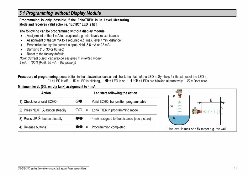
Procedure of programming: press button in the relevant sequence and check the state of the LED-s. Symbols for the states of the LED-s: = LED is off, = LED is blinking, = LED is on, = LEDs are blinking alternatively = Dont care
Minimum level, (0%, empty tank) assignment to 4 mAAction Led state following the action
1) Check for a valid ECHO = Valid ECHO, transmitter programmable
2) Press NEXT button steadily = EchoTREK in programming mode
3) Press UP button steadily = 4 mA assigned to the distance (see picture)
4) Release buttons = Programming completed
B
B
Use level in tank or a fix target e.g. the wall

12 SE/SG-300 series two-wire compact ultrasonic level transmitters
Maximum level (100%, full tank) assignment to 20 mA
Action Led state following the action
1) Check for a valid ECHO = Valid ECHO, transmitter programmable
2) Press NEXT button steadily = EchoTREK in programming mode
3) Press UP button steadily = 20 mA as signed to the distance(see picture)
4) Release buttons = Programming completed
B
B
Use level in tank or a fix target e.g. the wall
“Error state” indication by the analogue signal (Check for a valid echo as above)As a result of this setting the value of the analogue output will be 3,8 mA; 22 mA or according last value (hold) until the error is ceased.
Action Led state following the action
1) Press button steadily = EchoTREK in programming mode2) Press any of the DOWN ,
ENTER E ,NEXT
buttons steadily
– hold last value= – 3,6 mA
– 22 mA
3) Release buttons = Programming completed

SE/SG-300 series two-wire compact ultrasonic level transmitters 13
Damping time setting (Check for a valid echo as above)
Action Led state following the action
1) Press ENTER E button steadily = EchoTREK in programming mode2) Press any of the NEXT ,
UP ,DOWN
buttons steadily
– 10 sec= – 30 sec
– 60 sec
3) Release buttons = Programming completed
RESET: Returning to the default (Check for a valid echo as above)
Action Led state following the action
1) Press NEXT button steadily = EchoTREK in programming mode
2) Press ENTER E button steadily = Default loaded
Indication of mistakes (by LEDs) made during programming
Action Led state following the action Possible correction
Attempted programming = blinking twice = no Echo Find a valid Echo
Attempted programming = blinking three times = no access possible With SAP-200 only See 5.2 (P99)
Attempted programming = blinking four times = EchoTREK not inLevel Meas Mode With SAP-200 only See 5.2 (P01)

14 SE/SG-300 series two-wire compact ultrasonic level transmitters
5.2 Programming with the SAP-200 Display ModuleThe EchoTREK should be adjusted to the process by programming the parameters. The SAP-200 Display Module can be used to display the parameters duringprogramming and measurement values during measurement.The SAP-200 supports two separately accessible programming modes representing 2-layers of programming complexity, depending on user choice.
PLUG-IN DISPLAY MODULE
QUICKSETFULL
PARAMETERACCESS
QUICKSET (5.2.4)Recommended as a simple and fast way to set up the EchoTREK by 6 basic parametersfor the following basic settings, marked by abbreviationseasy to remember• Engineering unit for the display (Metric or US)• Maximum measuring distance (H)• Assignment of min level to 4 mA• Assignment of max level to 20 mA• Error indication by the current output• Damping time
Full Parameter Access (5.2.5)All features of the EchoTREK such as:• Measurement configuration• Outputs• Measurement optimalisation• 11 pre-programmed tank shapes for volume calculation• 21 pre-programmed formula for flow metering• 32-point linearisation
SE/SG-300 series two-wire compact ultrasonic level transmitters 15
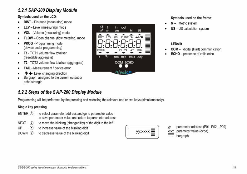
5.2.1 SAP-200 Disp lay ModuleSymbols used on the LCD:• DIST – Distance (measuring) mode• LEV – Level (measuring) mode• VOL – Volume (measuring) mode• FLOW – Open channel (flow metering) mode• PROG - Programming mode
(device under programming)• T1 - TOT1 volume flow totaliser
(resetable aggregate)• T2 - TOT2 volume flow totaliser (aggregate)• FAIL - Measurement / device error• - Level changing direction• Bargraph assigned to the current output or
echo strength
Symbols used on the frame:• M – Metric system• US – US calculation system
LEDS lit• COM – digital (Hart) communication• ECHO – presence of valid echo
5.2.2 Steps of the SAP-200 Display ModuleProgramming will be performed by the pressing and releasing the relevant one or two keys (simultaneously).
Single key pressingENTER E to select parameter address and go to parameter value
to save parameter value and return to parameter addressNEXT to move the blinking (changability) of the digit to the leftUP to increase value of the blinking digitDOWN to decrease value of the blinking digit yy:xxxx
yy parameter address (P01, P02…P99)xxxx parameter value (dcba)
bargraph

16 SE/SG-300 series two-wire compact ultrasonic level transmitters
Double key pressingPress the two keys simultaneously for desired programming step.
Enter into or quit programming modes Basic steps while parameter address is blinking Basic steps while parameter value is blinking
EQuickset
Full P
aram
eter
Acce
ssE
Return to default*
* LOAD readout ** CANCEL readout
Cancel all modifications **
Param
eterv
alue
Defau
lt
E
Display default value
* cancellation immediately active
Cancel all modifications
return to parameter address*
Param
eter v
alue
Actua
l
GET LEVEL functionSpecial function used only in level and distance measurement modes UP + DOWN Notes:If after pressing ENTER E blinking does not spring over from the parameter address to the parameter value this means that• the parameter is either a read-out type, or• the secret code prevents the modification (see P99)If the modification of the parameter value is not accepted i.e. the parameter value keeps blinking after pressing ENTER E ,• the modified value is either out of the range, or• the code entered is not a valid code
5.2.3 Indications of the SAP-200 and LED Status
4...20mA
LED indication• ECHO-LED
lit in case ofvalid echo.
• COM-LEDsee description of HART

SE/SG-300 series two-wire compact ultrasonic level transmitters 17
SAP-200 indicationsDepending on the measurement one of thebelow symbols will lit and the processvalue displayed (see P01 chapter 6.1).Engineering units will be indicated directly(°C, °F and mA) and by the lit arrowshowing towards them on the frame• DIST distance• LEV level• VOL volume• FLOW flow• T1/T2 totalised values• FAIL (blinking) Error code displayed
For paging readouts NEXT key shouldbe pressed.
The following process values can be displayed
• Volume / Flow – if programmed so• Level – if programmed so• Distance – if programmed so• Warning indications – FAIL blinking
Display screens can be scrolled by pressing key NEXT .To return to the screen of the selected measurement modekey ENTER E should be pressed (see P01 chapter 6.1)Temperature can be displayed by pressing UP .
Current output value can be displayedby pressing DOWN .
5.2.4 QUICKSETRecommended as a simple and fast way to start up EchoTREK.QUICKSET programming (aided by 6 screens) is used in uncomplicated level meteringapplications to set the 6 basic parameters. The other parameters can only be modified in the FullParameter Access Mode see 5.1 (P01).
The instructions of this programming mode are also to be found on the front panel above theDisplay Module socket.
(°C/°F)
(mA) (Error)
(Vol/Flow)
(Distance)
See P01for possible readouts

18 SE/SG-300 series two-wire compact ultrasonic level transmitters
Keys Function
ENTER E + DOWN (press for min 3 secs!) Enter or exit QUICKSET programming mode
UP , DOWN , NEXT Increase/decrease and move left the blinking digit
UP + DOWN “GET LEVEL" - display actual level measured by the EchoTREK
ENTER E Save readout and step to the next screenNEXT + UP Quit Current Output Scaling without saving the modifications (CANCEL))NEXT + DOWN Display of the DEFAULT value.
Screens ActionsAPplicationxx= select “EU” (European) for metric or “US” for US engineering units (Use UP / DOWN keys)yy= indicating “Li” for liquidsDEFAULT: EU
Programming of this parameter will result in loading the factory default with the corresponding engineering units.
H = xxxx maximum measuring distance – Distance between transducer face and tank bottomManual: set value (Use UP / DOWN / NEXT keys) and save it (by ENTER E )Automatic: use the “GET LEVEL” function (UP + DOWN ) to obtain actual measured value with level in tank or a fixedtarget, i.e. wall. (“GET LEVEL” functions only if ECHO LED is lit) and save it as above.DEFAULT: maximum measuring distance [m], see Technical Data Table
4 mA xxxx – level value assigned to 4 mA current outputManual: set level value (by UP / DOWN / NEXT keys) and save it (by ENTER E )Automatic: use the “GET LEVEL” function (UP + DOWN ) to display the actual measured value with level in tank or afixed target, i.e. wall. (“GET LEVEL” functions only if ECHO LED is lit) and save it as above.DEFAULT: 0 m (0%, Empty tank)
H:xxxx
AP:xxyy
4:xxxx

SE/SG-300 series two-wire compact ultrasonic level transmitters 19
Screens Actions20 mA xxxx – level value assigned to 20 mA current outputManual: set level value (Use UP / DOWN / NEXT keys) and save it (by ENTER E )Automatic: use the “GET LEVEL” function (UP + DOWN ) to obtain actual measured value with level in tank or a fixedtarget, i.e. wall. (“GET LEVEL” functions only if ECHO LED is lit) and save it as above.DEFAULT: max. level = max. measuring distance – dead band [m] (100%, Full tank) (See Technical Data Table)
Error indication by the current output – select “Hold”, 3.6 mA or 22 mA (by UP / DOWN key) and save it as above.
DEFAULT: hold last value
damping time: select required damping time (by UP / DOWN key) and save it as above.
DEFAULT: 60 sec for liquids, 300 sec for solids
Note: – Current output can also be programmed for inverted operation: 4 mA= 100% (Full), 20 mA= 0% (Empty)– Description of failures can be found under the chapter 7 Error codes.
5.2.5 Full Parameter AccessFull Parameter Access is the highest programming level to access all features provided by the EchoTREK
Description of all parameters can be found under the chapter “Parameter” (Chapter 6.).
Keys Function
ENTER E + NEXT (press for 3 seconds)
Enter or exit Full Parameter Access programming mode.
In this programming mode, the display will indicate:
yy Parameter Address (P01, P02 … P99)xxxx Parameter Value (dcba)
bargraphyy:xxxx
Er:xxxx
20:xxxx
dt: xxxx

20 SE/SG-300 series two-wire compact ultrasonic level transmitters
Measuring is going on during programming in accordance with the old parameter set. New parameter set will be valid after returning to theMeasurement to the Programming Mode.Steps and indications of the Full Parameter Access programming mode
pressing Keys while Parameter Address is blinking while Parameter Value is blinking
ENTER E Go to the Parameter Value Save the modification of the Parameter Value and returnto the Parameter Address
NEXT + UP Cancel all modifications of the actual programming phase.Pressing for 3 sec is required while CANCEL will be displayedfor warning
Neglect the modification of the Parameter Value.and return to the Parameter Address without saving themodifications
NEXT + DOWN Reset entire device to Factory Default.Since this action will reset all parameters, “LOAD” will appear onthe display:- to confirm, press- to escape, press any other key- Exception: clearing TOT 1 (See at P77)
Display default of the Parameter Values(it can be saved by pressing ENTER E )
NEXT Move blinking (changeability) of the digit to the leftUP / DOWN Modify the blinking digit (increase, decrease) or scroll up/down

SE/SG-300 series two-wire compact ultrasonic level transmitters 21
6. PARAMETERS – DESCRIPTIONS AND PROGRAMMING
6.1 Measurement ConfigurationP00: - cba Application/Engineering Units
Programming of this parameter will result in loading the factory default with the corresponding engineering units.
a Operating (measurement) mode0 Liquid level measurement
b Engineering units(according to “c”)
Metric US0 m ft1 cm inch
Attention: mind the sequence!When programming this parameter the right value “a” will be blinking first.
c Calculation system0 Metric1 US
FACTORY DEFAULT: 000
22 SE/SG-300 series two-wire compact ultrasonic level transmitters
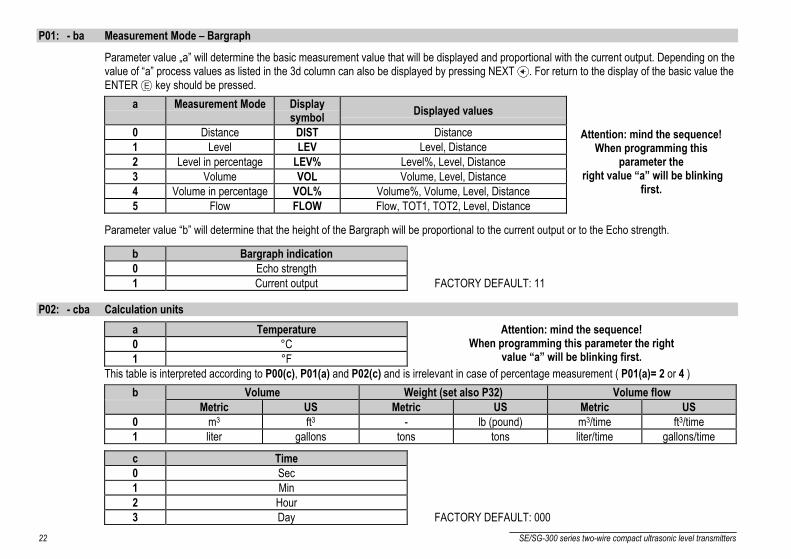
P01: - ba Measurement Mode – Bargraph
Parameter value „a” will determine the basic measurement value that will be displayed and proportional with the current output. Depending on thevalue of “a” process values as listed in the 3d column can also be displayed by pressing NEXT . For return to the display of the basic value theENTER E key should be pressed.
a Measurement Mode Displaysymbol Displayed values
0 Distance DIST Distance1 Level LEV Level, Distance2 Level in percentage LEV% Level%, Level, Distance3 Volume VOL Volume, Level, Distance4 Volume in percentage VOL% Volume%, Volume, Level, Distance5 Flow FLOW Flow, TOT1, TOT2, Level, Distance
Attention: mind the sequence!When programming this
parameter the right value “a” will be blinking
first.
Parameter value “b” will determine that the height of the Bargraph will be proportional to the current output or to the Echo strength.
b Bargraph indication0 Echo strength1 Current output FACTORY DEFAULT: 11
P02: - cba Calculation unitsa Temperature0 °C1 °F
Attention: mind the sequence!When programming this parameter the right
value “a” will be blinking first.This table is interpreted according to P00(c), P01(a) and P02(c) and is irrelevant in case of percentage measurement ( P01(a)= 2 or 4 )
b Volume Weight (set also P32) Volume flowMetric US Metric US Metric US
0 m3 ft3 - lb (pound) m3/time ft3/time1 liter gallons tons tons liter/time gallons/time
c Time0 Sec1 Min2 Hour3 Day FACTORY DEFAULT: 000
SE/SG-300 series two-wire compact ultrasonic level transmitters 23
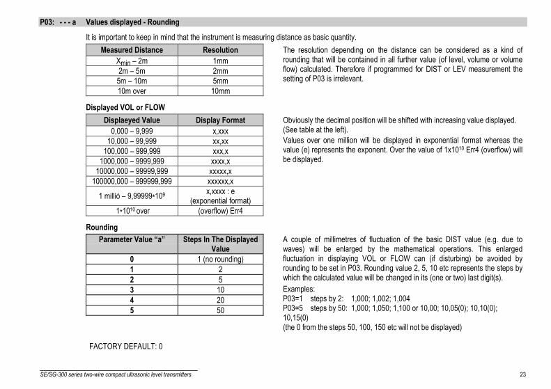
P03: - - - a Values displayed - Rounding
It is important to keep in mind that the instrument is measuring distance as basic quantity.Measured Distance Resolution
Xmin – 2m 1mm2m – 5m 2mm5m – 10m 5mm10m over 10mm
The resolution depending on the distance can be considered as a kind ofrounding that will be contained in all further value (of level, volume or volumeflow) calculated. Therefore if programmed for DIST or LEV measurement thesetting of P03 is irrelevant.
Displayed VOL or FLOWDisplaeyed Value Display Format
0,000 – 9,999 x,xxx10,000 – 99,999 xx,xx
100,000 – 999,999 xxx,x1000,000 – 9999,999 xxxx,x
10000,000 – 99999,999 xxxxx,x100000,000 – 999999,999 xxxxxx,x
1 millió – 9,99999*109 x,xxxx : e(exponential format)
1*1010 over (overflow) Err4
Obviously the decimal position will be shifted with increasing value displayed.(See table at the left).Values over one million will be displayed in exponential format whereas thevalue (e) represents the exponent. Over the value of 1x10¹⁰ Err4 (overflow) willbe displayed.
RoundingParameter Value “a” Steps In The Displayed
Value0 1 (no rounding)1 22 53 104 205 50
A couple of millimetres of fluctuation of the basic DIST value (e.g. due towaves) will be enlarged by the mathematical operations. This enlargedfluctuation in displaying VOL or FLOW can (if disturbing) be avoided byrounding to be set in P03. Rounding value 2, 5, 10 etc represents the steps bywhich the calculated value will be changed in its (one or two) last digit(s).Examples:P03=1 steps by 2: 1,000; 1,002; 1,004P03=5 steps by 50: 1,000; 1,050; 1,100 or 10,00; 10,05(0); 10,10(0);10,15(0)(the 0 from the steps 50, 100, 150 etc will not be displayed)
FACTORY DEFAULT: 0

24 SE/SG-300 series two-wire compact ultrasonic level transmitters
P04 Maximum Distance to be Measured (H)The maximum distance to be measured is the greatest distance between the surface of the transducer and the level to be measured.This is the only parameter that has to be programmed for each application other than distance (however to avoid disturbing effect ofpossible multiple echos it is suggested to do this in distance measurement applications too).Values of the maximum measuring distance will be displayed as below.
Engineering Unit Display Formatm x,xxx or xx,xxcm xxx,xft xx,xx or xxx,x
inch xxx,x
The factory programmed, greatest distances (DEFAULT values) which can be measured by the units are listed in the table below. For the actualapplication the maximum distance to be measured i.e. the distance between the sensor and the bottom of the tank should be entered in P04.To obtain the best accuracy, measure this distance in the empty tank with the EchoTREK by using the “GET LEVEL” function (by double keypressing of UP + DOWN ) provided the bottom is flat. Enter the actual measured value displayed as P04.
Maximum measuring distance [m]EchoTREKTransducer material
PP / PVDFTransducer material
PTFETransducer material
Stainless steelS-39 4/13 3/10 -S-38 6/20 5/16 -S-37 8/26 6/20 -S-36 10/33 - 7/23S-34 15/49 - 12/39
FACTORY DEFAULT: according to the table

SE/SG-300 series two-wire compact ultrasonic level transmitters 25
P05: Minimum measuring distance (Dead zone- Close-end blocking)
The EchoTREK will not accept any echo within the blocking distance set here.
Automatic Close-end-blocking (Automatic Dead Band control)By using the factory default value, the unit will automatically set the smallest possible close-end-blocking distance i.e. the dead band.Manual close-end-blockingManual close-end-blocking should be used for example to block out the echo originating from the bottom rim of a stand-off pipe or from anyobject protruding into the ultrasonic cone near to the transmitter.By entering a value, higher than the factory default, the minimum measuring range will be extended and fixed to the specified value.To return to the factoryprogrammed (DEFAULT value) of the minimum measuring distance press NEXT + DOWN .
Minimum measuring distance XM
EchoTREK Sensor materialPP / PVDF
Sensor materialPTFE
Sensor materialStainless steel
S-39 0.2 0.2 -S-38 0.25/0 0.25 -S-37 0.35 0.35 -S-36 0.35 - 0.4S-34 0.45 - 0.55
FACTORY DEFAULT: automatic dead band control

26 SE/SG-300 series two-wire compact ultrasonic level transmitters
P06: Far end blocking
Far end blocking is used to neglect incorrectlevel/volume readings and output actions below apre-set level programmed in P06.
A). Level measurementThe far-end blocking can be used to avoid disturbingeffect of stirrer or heaters at the bottom of the tanks.If the level of the medium sinks below theblocked out range:- ”Sub 0” will be indicated for the level and volume- Distance value is not interpretable- Current output will hold the value corresponding to
the far end blocking levelP06Far end blocking
LevelVolume
"SUB 0" indication below this level
4m
A
mA
20m
A
H
If the medium level is above the blocked out range:The calculation of level and volume will be based on the programmed tank dimensions, therefore the measured or calculated process valueswill not be influenced in any way, by the far end blocking value.
B). Open channel flow meteringFar end blocking will be used for those small levels below which the accurate volume flow calculation is no longer possible.
If the liquid level in the flume/weir falls below the blocked out range:The EchoTREK will act as follows:- Indicate ”No Flow” on the Display- Hold last valid data on the current output.
If the level in the flume/weir is above the blocked out range:The calculation of volume flow will be based on the programmed flume/weir data; therefore the measurement values will not be influenced in anyway, by the far end blocking value.
FACTORY DEFAULT: 0

SE/SG-300 series two-wire compact ultrasonic level transmitters 27
6.2 Current OutputP10: Value (of distance, level, volume or flow) assigned to 4 mA current output
P11: Value (of distance, level, volume or flow) assigned to 20 mA current output
Values are interpreted according to P01(a). Please note that in case of programming for (LEV or VOL) % measurement the min and max valuehas to be entered in the relevant engineering units of LEV (m, ft) or VOL (m3, ft3).
Assignment can be made so that the proportion between the change of the (measured or calculated) process value and the change of the currentoutput be either direct or inverse. E.g. lev 1 m assigned to 4mA and lev 10 m assigned to 20 mA represents direct proportion and lev 1 massigned to 20 mA and lev 10 m assigned to 4 mA represents the inverse proportion.
FACTORY DEFAULT:P10 0 level (max distance)P11 max level (min distance) H
P12: - - - a Error indication by the current output
In case of error the EchoTREK will provide one of the current outputs below. (For errors and their interpretation see Chapter 7).a ERROR INDICATION (ACCORDING TO NAMUR)0 Hold last value1 3.6 mA2 22 mA
FACTORY DEFAULT: 0

28 SE/SG-300 series two-wire compact ultrasonic level transmitters
6.3 Measurement OptimisationP20: - - - a Damping
This parameter can be used to reduce unwanted fluctuation of the display and output.LIQUIDS
aDamping
time(seconds)
None/moderatefume or waves
Heavy/dense fume orturbulent waves
0 no filter1 3 applicable not recommended2 6 recommended applicable3 10 recommended recommended4 30 recommended recommended5 60 recommended recommended
FACTORY DEFAULT: 60 sec
P22: - - - a Dome top tank compensation
This parameter can be used to reduce disturbing effect of possible multiple echos.a Compensation Applied0 OFF In case the EchoTREK is not mounted in the centre of the top and the top is flat.1 ON In case the EchoTREK is mounted in the centre of a tank with dome-shaped top
FACTORY DEFAULT: 0
P24: - - - a Target tracking speed
In this parameter evaluation can be speed up at the expense of the accuracy.a Tracking speed Remark0 Standard For most applications1 Fast For fast changing level
2 SpecialOnly for special applications (measuring range is reduced to 50% of the nominal value)
The measuring window is inactive and the EchoTREK will respond practically instantly to any target.Recommended to fast target tracking, but usually not applicable for level metering.
FACTORY DEFAULT: 0

SE/SG-300 series two-wire compact ultrasonic level transmitters 29
P25: - - - a Selection of Echo within the measuring window
A so-called measuring window is formed around the echo signal. The position of this measuring window determines the flight time for calculationof the distance to the target. (the picture below can be seen on the test oscilloscope)
Receivedsignalamplitude
Echo 1. Echo 2.
Some applications involve multiple (target + disturbing) echoes even within the measuring window. Basic echo selection will be done by theQuest + software automatically. This parameter only influences the echo selection within the measuring window.
a Echo in the window tobe selected
Remark
0 With the highestamplitude For most applications (both with liquids and solids)
1 First one For liquids applications with multipleechoes within the Measuring Window
FACTORY DEFAULT: 0
P26: Level elevation rate (filling speed) (m/h)
P27: Level descent rate (emptying speed) (m/h)
These parameters provide additional protection against echo loss in applications involving very heavy fuming.The parameters must not be smaller than the fastest possible filling/emptying rate of the actual technology.For all other applications, use the factory default setting.
FACTORY DEFAULT:2000 for both P26 and P27

30 SE/SG-300 series two-wire compact ultrasonic level transmitters
P28: - - - a Echo loss indicationa Echo loss indication Remark
0 Delayed indication
During echo-loss, display and analogue output will hold last value.If the echo-loss prevails for 10 sec plus the time period set in P20 (damping time), the reading on thedisplay will change to "no Echo" and the outputs will change according to the "Error Indication Mode"preset in P12
Readout holding valuefor "P20" time
t
No Echo
Echo loss LED goes out
Current output holding
P12 = 2
holding value
current 22 mA
P12 = 1current 3,6 mA
P12 = 0
value blinkingfor "P20" time
1 No indication For the time of echo-loss, display and analogue output will hold last value.
2 Advance to full During echo-loss in case of filling, the reading on the display and analogue output will shift towards the"full" tank state with a level elevation rate (filling speed) preset in P26
3 Immediate indication In case of echo-loss, the display will immediately change to “no Echo”, and the outputs will changeaccording to the "Error Indication Mode" preset in P12
4 Empty tank indicationEcho-loss may occur in completely empty tanks with a spherical bottom due to deflection of theultrasonic beam, or in case of silos with an open outlet.If the echo is lost when the tank is completely empty, the indication will correspond to empty tank, in allother cases echo-loss indication will function according to the “Delayed”.
FACTORY VALUE: 0
SE/SG-300 series two-wire compact ultrasonic level transmitters 31
P29: Blocking out of disturbing object
One fixed object in the tank, disturbing the measurement, can be blocked out.Enter distance of the object from the transducer. Use the Echo Map (P70) to read out the precise distance of disturbing objects.
FACTORY DEFAULT: 0P31: Sound velocity at 20°C (m/sec or ft/sec depending on P00(c) )
Use this parameter if the sound velocity in the gases above the measured surface differs largely from that of in air.Recommended for applications where the gas is more or less homogeneous. If it is not, the accuracy of the measurement can be improved using32-point linearisation (P48, P49).For sound velocities in various gases see section “Sound Velocities”.
FACTORY DEFAULT: Metric (P00: “EU”): 343.8 m/s, US (P00: “US”): 1128 ft/s
P32: Specific gravity
If you enter a value (other than “0”) of specific gravity in this parameter, the weight will be displayed instead of VOL.
FACTORY DEFAULT: 0 [kg/dm3] or [lb/ft3] depending on P00(c)

32 SE/SG-300 series two-wire compact ultrasonic level transmitters
6.4 Volume MeasurementP40: - - ba Tank shape
ba Tank shape Also to be setb0 Standing cylindrical tank shape (value of “b” as below) P40(b), P4101 Standing cylindrical tank with conical bottom P41, P43, P4402 Standing rectangular tank (with chute) P41, P42, (P43, P44, P45)b3 Lying cylindrical tank shape (value of “b” as bellow) P40(b), P41, P4204 Spherical tank P41
Attention!The value „a” determining theshape of the tank should be
set first.
FACTORY DEFAULT: 00P41-45: Tank dimensions
Standing cylindrical tankwith hemispherical bottom
Standing cylindrical tankwith conical bottom
Standing rectangular tankwith or without chute
b=0
P40b=1
b=2b=3
If no chuteP43, P44 and P45=0
Lying cylindrical tank Spherical tank
b=0b=1b=2b=3P40

SE/SG-300 series two-wire compact ultrasonic level transmitters 33
6.5 Volume Flow MeasuringP40: - - ba Devices, formula, data
ba Devices, formula, data Also to be setType Calculation formula Qmin [l/s] Qmax [l/s] “P” [cm]
00 GPA-1P1 Q[l/s]= 60.87*h1.552 0.26 5.38 30 P4601 GPA-1P2 Q[l/s]= 119.7*h1.553 0.52 13.3 34 P4602 GPA-1P3 Q[l/s]= 178.4*h1.555 0.78 49 39 P4603 GPA-1P4 Q[l/s]= 353.9*h1.558 1.52 164 53 P4604 GPA-1P5 Q[l/s]= 521.4*h1.558 2.25 360 75 P4605 GPA-1P6 Q[l/s]= 674.6*h1.556 2.91 570 120 P4606 GPA-1P7 Q[l/s]= 1014.9*h1.556 4.4 890 130 P4607 GPA-1P8 Q[l/s]= 1368*h1.5638 5.8 1208 135 P4608
Nive
lco P
arsh
all fl
ume
GPA-1P9 Q[l/s]= 2080.5*h1.5689 8.7 1850 150 P4609 General PARSHALL flume P46, P4210 PALMER-BOWLUS (D/2) P46, P4111 PALMER-BOWLUS (D/3) P46, P4112 PALMER-BOWLUS (Rectangular) P46, P41, P4213 Khafagi Venturi P46, P4214 Bottom-step weir P46, P4215 Suppressed rectangular or BAZIN weir P46, P41, P4216 Trapezoidal weir P46, P41, P4217 Special trapezoidal (4:1) weir P46, P4218 V-notch weir P46, P4219 THOMSON (90°-notch) weir P4620 Circular weir P46, P4121 General flow formula: Q[l/s]= 1000*P41*hP42, h [m] P46, P41, P42
FACTORY DEFAULT: 0

34 SE/SG-300 series two-wire compact ultrasonic level transmitters
P41-45: Flume/weir dimensions
FACTORY DEFAULT: 0P40= 00 . . . .
Nivelco Parshall flumes (GPA1P1 … GPA-1P9)For further details see the Manual of the Parshall flume
Sensor
P46
Sensor
P40= 09 General Parshall flume0.305 < P42(width) <2.44
0.026
Q[m3/s]= 0.372*P42*(h/0.305)1.569*s
2.5 < P42Q[m3/s]= K*P42*h1.6
P= 2/3*A
A
h
P46
Sensor
SensorP42
P
s[m] K3.05 2.4504.57 2.4006.10 2.3707.62 2.3509.14 2.34015.24 2.320

SE/SG-300 series two-wire compact ultrasonic level transmitters 35
P40= 10Palmer-Bowlus (D/2) flume
Q[m3/s]= f(h1/P41)*P412.5,where h1[m]= h+(P41/10) P04
P46
h
P41D
D/10
P40= 11Palmer-Bowlus (D/3) flume
Q[m3/s]= f(h1/P41)*P412.5, where h1[m]= h+(P41/10) P04
P46
h
P41D
D/10
P40= 12Palmer-Bowlus (Rectangular) flume
Q[m3/s]= C*P42*h1.5,where C= f(P41/P42)
D
P42
P46
P04
h
D/10
P41

36 SE/SG-300 series two-wire compact ultrasonic level transmitters
P40= 13Khafagi Venturi flume
Q[m3/s]= P42*1.744*h1.5 + 0.091*h2.5
15cm
P46
Sensor
h
P42
Sensor
P40= 14Bottom step weir0.0005 < Q[m3/s] < 10.3 < P42[m] < 150.1 < h[m] < 10Q[m3/s]= 5.073*P42*h1.5
Accuracy: ±10%
P40=14
P46
P42
h
P40= 15Suppressed rectangular or BAZIN weir0.001 < Q[m3/s] < 50.15 < P41[m] < 0.80.15 < P42[m] < 30.015 < h[m] < 0.8Q[m3/s]= 1.7599*[1+(0.1534/P41)]*P42*(h+0.001)1.5
Accuracy: ±1%
P40=15
P04
P46
h
P42
P41

SE/SG-300 series two-wire compact ultrasonic level transmitters 37
P40= 16Trapezoidal weir0.0032 < Q[m3/s] < 8220 < P41[°] < 1000.5 < P42[m] < 150.1 < h[m] < 2Q[m3/s]= 1.772*P42*h1.5+1.320*tg(P41/2)*h2.47Accuracy: ±5%
P40=16
P04
P46
h
P42 P41
P40= 17Special Trapezoidal (4:1) weir0.0018 < Q[m3/s] < 500.3 < P42[m] < 100.1 < h[m] < 2Q[m3/s]= 1.866*P42*h1.5Accuracy: ±3%
1
4
P40=17
P46
P04 h
P42
P40= 18V-notch weir0.0002 < Q[m3/s] < 120 < P42[°] < 1000.05 < h[m] < 1Q[m3/s]= 1.320*tg(P42/2)*h2.47Accuracy: ±3%
P40=18
h
P46
P42P04

38 SE/SG-300 series two-wire compact ultrasonic level transmitters
P40= 19THOMSON (90°-notch) weir0.0002 < Q[m3/s] < 10.05 < h[m] < 1Q[m3/s]= 1.320*h2.47Accuracy: ±3%
P46
P40=19
P04 h 90
P40= 20Circular weir0.0003 < Q[m3/s] < 250.02 < h[m] < 2Q[m3/s]= m*b*D2.5
m= 0.555+0.418h/P41+(P41/(0.11*h))Accuracy: ±5%
P40=20
P46
P04 h P41
P46: Distance between transducer face and level of Q=0
P46 is always the distance between the transducer face and the level, where the volume flow is 0.
FACTORY DEFAULT: 0

SE/SG-300 series two-wire compact ultrasonic level transmitters 39
6.6 32-Point LinearisationP47: - - - a Linearisation
Linearisation is the method of assigning requested (calibrated or calculated) level, volume or flow to values measured by the transmitter.It can be used for instance if the sound velocity is not known (LEVEL⇒LEVEL) or in the case of tank with other shape than under 6.4 or openchannel other than under 6.5 (LEVEL ⇒ VOLUME or LEVEL ⇒ FLOW).
a Linearisation0 OFF (FACTORY DEFAULT)1 ON
P48: Linearisation tableData-pairs of the linearisation table are handled in a 2x32 matrix, consisting of two columns.
Left column “L” Right column “r”LEVEL measured LEVEL or VOLUME or FLOW to be transmitted and displayed
The left column values (indicated on the display as “L”) contain the measured LEVEL values.The right column values (indicated on the display as “r”) contain the calibrated values and are interpreted according to the selected measurementvalue in P01(a).
}
+
+
+
+
+
Number of data pairsin the table
LevelvolumeflowEnter
the tableAddress of data pair
Left handcolumn
Levelmeasuredvalue
Canceling last modification
Right handcolumn
to be transmittedand displayed
Entering values
Copying measured value
Neglect modification (CANCEL)
Entering "0" (closing up the tble)
Exit thetable

40 SE/SG-300 series two-wire compact ultrasonic level transmitters
Conditions of correct programming of the data pairsLeft column “L” Right column “r”
L(1)= 0 r(1)L(i) r(i)
: :L(j) r(j)
The table must always start with: L(1)= 0 and r(1)= value (assigned to 0 level)The table must be ended either with the 32nd data pair i.e. j=32 or if the linearisation table contains less than 32 data-pairs j<32, the table must be closedby a level value “0” e.g. L(j<32)= 0.The EchoTREK will ignore data after recognising level value “0” with serial number other than “1”.If the above conditions are not met, error codes will be displayed (see chapter: Error Codes).
6.7 Informational Parameters (Read Out Parameters)P60: Overall operating hours of the unit (h)
Indication varies according to the elapsed time:Operating hours Indication form
0 to 999.9h xxx,x1000 to 9999h xxxx
Over 9999h X,xx: e meaning x,xx 10e
P61: Time elapsed after last switch-on (h)
Indication same as in P60.
P64: Actual temperature of the transducer (°C/°F)P65: Maximum temperature of the transducer (°C/°F)P66: Minimum temperature of the transducer (°C/°F)
In case of a breaking in the temperature measuring Pt10 element „PtErr” will be displayed (See Chapter 7). The transmitter will performtemperature correction corresponding to 20ºC.

SE/SG-300 series two-wire compact ultrasonic level transmitters 41
P70: Number of Echoes / Echo Map
EchoTREK is monitoring the echoconditions.
Entering this parameter will save theactual echo map.
Number, distance and amplitude of theseechoes can be read-out one by one.
yy : xxxxyy : xxxx70 : _ _ XX
yy : xxxx yy : xxxx
Number of
yy Serial numberof the echo
xx value ofDIST or AMPL
echos
(DISTANCE)
(DISTANCE)
(AMPLITUDE)
(AMPLITUDE)
P71: Distance of the of Measuring Window
P72: Amplitude of the Echo in the Measuring
P73: Echo Position (time) :(ms)
P74: Signal To Noise RatioRatio Measurement conditions
Over 70 ExcellentBetween 70 and 30 Good
Under 30 Unreliable
P75: Blocking Distance
The actual close-end blocking distance will be displayed (provided automatic blocking was selected in P05).
42 SE/SG-300 series two-wire compact ultrasonic level transmitters
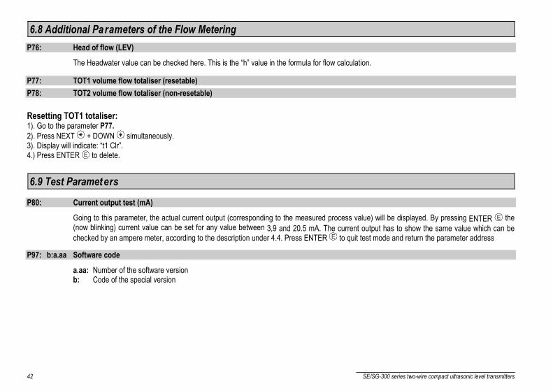
6.8 Additional Parameters of the Flow MeteringP76: Head of flow (LEV)
The Headwater value can be checked here. This is the “h” value in the formula for flow calculation.
P77: TOT1 volume flow totaliser (resetable)P78: TOT2 volume flow totaliser (non-resetable)
Resetting TOT1 totaliser:1). Go to the parameter P77.2). Press NEXT + DOWN simultaneously.3). Display will indicate: “t1 Clr”.4.) Press ENTER E to delete.
6.9 Test Parameters
P80: Current output test (mA)
Going to this parameter, the actual current output (corresponding to the measured process value) will be displayed. By pressing ENTER E the(now blinking) current value can be set for any value between 3,9 and 20.5 mA. The current output has to show the same value which can bechecked by an ampere meter, according to the description under 4.4. Press ENTER E to quit test mode and return the parameter address
P97: b:a.aa Software code
a.aa: Number of the software versionb: Code of the special version

SE/SG-300 series two-wire compact ultrasonic level transmitters 43
6.10 SimulationThis function enables the user to test the settings of the outputs. The EchoTREK can simulate the static or continuous change of level accordingto the simulation cycle time, high level and low level set in P85, P86 and P87. (The simulation levels must be within the programmed measuringrange set in P04 and P05.)
After selecting simulation type in P85 and setting simulation values Measurement Mode has to be re-entered. While the EchoTREK is insimulation mode the DIST, LEV or VOL symbol will be blinking. To quit Simulation Mode P84= 0 should be set.
P84: - - - x Selection of the simulation
X Simulation type0 No simulation
1 The level changes continuously up and down between the level values setin P86 and P87 with a cycle time set in P85
P87
P86
P85
LEV [m]
t [sec]
P85: Cycle time for simulation (sec)P86: Simulated low level value (m)P87: Simulated high level value (m)
6.11 Access LockP99: dcba Access Lock by Secret Code
The purpose of this feature is to provide protection against accidental (or intentional) re-programming of parameters.The Secret Code can be any value other than 0000. Setting a Secret Code will automatically be activated when the EchoTREK is returned to theMeasurement Mode. If the Secret Code is activated, the parameters can only be viewed, this is indicated by the a flashing colon “:” between theparameter address and the parameter value.In order to program the device locked by a secret code, first enter the Secret Code in P99. The Secret Code is re-activated each time theEchoTREK is returned to Measurement Mode.To delete the Secret Code, enter the Secret Code in P99. After confirming it with [E] re-enter the parameter P99 and enter 0000.[dcba (Secret Code) ] → [E] → [E] → [0000] → [E] ⇒ Secret Code deleted
44 SE/SG-300 series two-wire compact ultrasonic level transmitters
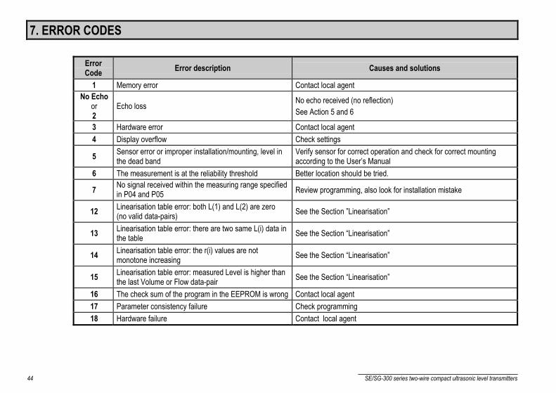
7. ERROR CODES
ErrorCode Error description Causes and solutions
1 Memory error Contact local agentNo Echo
or2
Echo loss No echo received (no reflection)See Action 5 and 6
3 Hardware error Contact local agent4 Display overflow Check settings
5 Sensor error or improper installation/mounting, level inthe dead band
Verify sensor for correct operation and check for correct mountingaccording to the User’s Manual
6 The measurement is at the reliability threshold Better location should be tried.
7 No signal received within the measuring range specifiedin P04 and P05 Review programming, also look for installation mistake
12 Linearisation table error: both L(1) and L(2) are zero(no valid data-pairs) See the Section ”Linearisation”
13 Linearisation table error: there are two same L(i) data inthe table See the Section “Linearisation”
14 Linearisation table error: the r(i) values are notmonotone increasing See the Section “Linearisation”
15 Linearisation table error: measured Level is higher thanthe last Volume or Flow data-pair See the Section “Linearisation”
16 The check sum of the program in the EEPROM is wrong Contact local agent17 Parameter consistency failure Check programming18 Hardware failure Contact local agent

SE/SG-300 series two-wire compact ultrasonic level transmitters 45
8. PARAMETER TABLEPar. Page Description Value Par. Page Description Value
d c b a d c b aP00 21 Application/Engineering Units P32 31 Specific gravityP01 22 Measurement Mode P33 N.A.P02 22 Calculation units P34 N.A.P03 23 Rounding P35 N.A.P04 24 Maximum Measuring Distance P36 N.A.P05 25 Minimum Measuring Distance P37 N.A.P06 26 Far End Blocking P38 N.A.P07 N.A. P39 N.A.P08 N.A. P40 33 Selection of tank shape/ open channelP09 N.A. P41 32 Dimensions of tank / Open ChannelP10 27 Value assigned to „4 mA” P42 32 Dimensions of tank / Open ChannelP11 27 Value assigned to „20 mA” P43 32 Dimensions of tank / Open ChannelP12 27 “Error” indication by the current output P44 32 Dimensions of tank / Open ChannelP13 N.A. P45 32 Dimensions of tank / Open ChannelP14 N.A. P46 38 Dist. Btw. Transducer face and level of Q=0P15 N.A. P47 39 LinearisationP16 N.A. P48 39 Linearisation tableP17 N.A. P49 N.A.P18 N.A. P50 N.A.P19 N.A. P51 N.A.P20 28 Damping P52 N.A.P21 N.A. P53 N.A.P22 28 Dome top tank compensation P54 N.A.P23 N.A. P55 N.A.P24 28 Target tracking speed P56 N.A.P25 29 Selection of Echo in the measuring window P57 N.A.P26 29 Level elevation rate P58 N.A.P27 29 Level descent rate P59 N.A.P28 30 Echo loss indication P60 40 Overall operating hours of the unitP29 31 Blocking out of disturbing object P61 40 Time elapsed after last switch-onP30 N.A. P62 N.A.P31 31 Sound velocity in different gases P63 N.A.

46 SE/SG-300 series two-wire compact ultrasonic level transmitters
Par. Page Description Value Par. Page Description Valued c b a d c b a
P64 40 Actual temperature of the transducer P82 N.A.P65 34 Maximum temperature of the transducer P83 N.A.P66 40 Minimum temperature of the transducer P84 43 Simulation modeP67 N.A. P85 43 Simulation cycle timeP68 N.A. P86 43 Simulation low levelP69 N.A. P87 43 Simulation high levelP70 41 Echo Map P88 N.A.P71 41 Distance of the measuring window P89 N.A.P72 41 Amplitude of the in the measuring window P90 N.A.P73 41 Distance of the in the measuring window P91 N.A.P74 41 Signal / noise ratio P92 N.A.P75 41 Blocking Distance P93 N.A.P76 42 Waterhead of the flow P94 N.A.P77 42 TOT1 volume flow totaliser P95 N.A.P78 42 TOT2 volume flow totaliser P96 N.A.P79 N.A. P97 42 Software codeP80 42 Current generator test P98 N.A.P81 N.A. P99 43 Access lock

SE/SG-300 series two-wire compact ultrasonic level transmitters 47
9. SOUND VELOCITIES IN DIFFERENT GASESThe following table contains the sound velocity of various gases measured at.
Gases Sound Velocity (m/s)Acetaldehyde C2H4O 252.8Acetylene C2H2 340.8Ammonia NH3 429.9Argon Ar 319.1Bensol C6H6 183.4Carbon dioxide CO2 268.3Carbon monoxide CO 349.2Carbon tetrachloride CCl4 150.2Chlorine Cl2 212.7Dimethyl ether CH3OCH3 213.4Ethane C2H6 327.4Ethanol C2H3OH 267.3Ethylene C2H4 329.4Helium He 994.5Hydrogen sulphide H2S 321.1Methane CH4 445.5Methanol CH3OH 347Neon Ne 449.6Nitrogen N2 349.1Nitrogen monoxide NO 346Oxygen O2 328.6Propane N.A. C3H8 246.5Sulphur hexafluoride SF6 137.8

sea3802a0600_01June 2002
Technical specification may be changed without notice.