Installation & Owner’s Manual - WAVE Home Solutions & Owner’s Manual This Manual Covers the...
12
July 9 th , 2014 Humidex CCC-103E/103R Rev. 2.0 Installation & Owner’s Manual This Manual Covers the Following Models CCC-103E Crawl Space CCC-103R Booster Fan Manufactured By: Air Tech Equipment Ltd. 1095 Ohio Rd. Boudreau-Ouest, NB Canada E4P 6N4 Tel: 1-800-416-9111 Web: www.humidex.ca
-
Upload
truongkhue -
Category
Documents
-
view
214 -
download
0
Transcript of Installation & Owner’s Manual - WAVE Home Solutions & Owner’s Manual This Manual Covers the...

July 9th, 2014 Humidex CCC-103E/103R Rev. 2.0
Installation & Owner’s
Manual
This Manual Covers the Following Models
CCC-103E � Crawl Space
CCC-103R � Booster Fan
Manufactured By: Air Tech Equipment Ltd.
1095 Ohio Rd. Boudreau-Ouest, NB Canada E4P 6N4 Tel: 1-800-416-9111 Web: www.humidex.ca

Humidex
Table of Contents
Service and Warranty 1
FOR CUSTOMER ASSISTANCE 1
CONSUMER LIMITED WARRANTY 2
Pre-Installation 4
INCLUDED COMPONENTS 4
TOOLS REQUIRED FOR INSTALLATION 4
KEY INSTALLATION FACTS 5
IMPORTANT – WHAT NOT TO DO 5
COMBUSTION APPLIANCE PRESENT IN DWELLING 5
IDEAL LOCATION OF THE UNIT 6
DUCTING 7
Installation 8
FACTORS TO CONSIDER 8
SELECTING THE DUCT LOCATION 8
PREPARING THE CCC-103E FOR INSTALLATION 9
ATTACHING THE FLEX, PIPE AND VENT 9
FASTEN UNIT TO THE WALL 10
INSTALLING THE CCC-103R 11
Unit Operations 14
THE CONTROL PANEL 14
HOW A HUMIDEX WORK 14
MAINTAINING YOUR HUMIDEX 16
Most Common Issues 17
MOLD, MILDEW AND MUSTY SMELL 17
Humidex
Before you call us
Questionnaire
1) Did you read this booklet?
2) Did you write down the information required on Page 3?
3) Is your speed control or dehumidistat properly set?
4) Are your crawlspace windows closed?
5) Is there sufficient replenishment air from the upper floor?
6) Is your crawlspace too cold?
7) Do you know the temperature of your main floor as well as your crawlspace floor?

Humidex
Schematic of Wiring
Follow the wiring schematic below when the fan and/or controls need to be serviced or replaced.
Humidex
Specifications 18
TECHNICAL DATA 18
DIMENSIONS 18
SCHEMATIC OF WIRING 19
BEFORE YOU CALL US 20

July 9th, 2014 Humidex CCC-103E/103R Rev. 2.0
1
For the Following Inquiries:
- Service - Parts - Accessories - Additional Customer Information
Please contact us by:
Phone: US 1-888-533-1348 Can.1-800-416-9111
Email: [email protected]
Website: www.humidex.ca
Service and Warranty
For Customer Assistance
To aid in answering questions if you call for service or warranty purposes, please record below the model and serial number located on the side of the unit.
Product Name:
Model #:
Date of Manufacturing:
Date of Purchase:
Serial #:
Dealer Name (If Any):
Humidex
Specifications
Technical Data
Model Voltage (V)
Amps (A)
Watts (W)
Airflow (CFM)
Capacity (Sq.Ft.)
CCC-103E 115 0.52 62 180 3000
CCC-103R - - - - -
All Units require a 115 VAC electrical outlet
Dimensions
Model Height (In.) Width (In.) Depth (In.)
CCC-103E 30.5” 11” 7.5”
CCC-103R 18.5” 11” 7.5”

Humidex
Most Common Issues
Mold, Mildew and Musty Smell
If mold or mildew is present prior to installing a Humidex, please have the contaminated area cleaned. Not doing so could cause the Humidex to spread that mold to other locations in the basement or crawlspace.
To avoid Mold, Mildew or Musty Smells:
- Follow the Recommendations on page 19 (Concerning New Installations in the summer).
To ensure the proper functionality of the Humidex:
- Verify that the replenishment air is flowing from the upstairs to the downstairs.
- Increase ventilation in remote areas with a portable fan.
- Any exposed pipes and ducts should be insulated.
- Dirt floor in crawl space should be covered with vapor barrier.
- Sump pump should be equipped with a cover.
- Rainwater from the roof should be directed away from the foundation.
- Landscaping should slope away from foundations.
- Insulating crawlspace will reduce the condensation and also reduce the energy cost during heating season.
Do not attempt to service the Humidex yourself. If you are not sure about certain functions, Please refer to page 2.
Humidex
Consumer Limited Warranty
Air Tech Equipment Ltd. Warrants to the first consumer that this Humidex product, when shipped in its original container, will be free from defective workmanship and materials, and agrees that it will, at its option, either repair the defect or replace the defective Product or part thereof with a new or remanufactured equivalent at no charge to the purchaser for the period(s) set forth below. The defective part must be returned to the manufacturer Air Tech Equipment Ltd. Transportation charges are the sole responsibility of the purchaser. This warranty does not apply to any appearance items of the Product nor to the additional excluded item(s) set forth below nor to any Product the exterior of which has been damaged or defaced, which has been subjected to improper voltage or other misuse, abnormal service or handling, or which has been altered or modified in design or construction. In order to enforce the rights under this limited warranty, the purchaser must fill out and return the warranty card as soon as possible. If your unit is not registered, a proof of purchase will be necessary should it require any services. Neither the sales personnel of the seller nor any other person is authorized to make any warranties other than those described herein, or to extend the duration of any warranties beyond the time period described herein on behalf of Air Tech Equipment Ltd.

Humidex
The warranties described herein shall be the sole and exclusive warranties granted by Air Tech and shall be the sole and exclusive remedy available to the purchaser. Correction of defects, in the manner and for the period of time described herein, shall constitute complete fulfillment of all liabilities and responsibilities of Air Tech to the purchaser with respect to the Product, and shall constitute full satisfaction of all claims, whether based on contract, negligence, and strict liability or otherwise. In no event shall Air Tech be liable, or in any way responsible, for any damages or defects in the Product which were caused by repairs or attempted repairs performed by anyone other than an authorized servicer, unless approved by Air Tech in writing. Nor shall Air Tech be liable or in any way responsible for any incidental or consequential economic or property damage. Warranty Period for this product:
Ten (10) year on parts from date of purchase.
Additional Items Excluded From Warranty Coverage (If Any):
Appearance items of the product, Exterior vent and any printed materials.
Where to obtain service:
From the Manufacturer. Please call US 1-888-533-1348, Can. 1-800-416-9111 If you require any information.
This warranty is not transferable and applies to residential use only. To obtain supply, accessory or product information, call US 1-888-967-9283, CAN 1-800-416-9111, or visit our website at www.humidex.ca
IMPORTANT To properly validate your warranty, you must fill out and return the warranty card as soon as possible. If your unit is not registered, a proof of purchase will be necessary should it require any services.
Humidex
Maintaining your Humidex
Do not store anything within a radius of 4 feet around the base of the Humidex.
Make sure the basement or crawlspace has adequate replenishment air from upstairs, from a location as far from the Humidex as possible.
The only maintenance needed for your Humidex is a periodic vacuuming of the dust accumulation at the intake grilles or louvers located at the bottom of the unit.
Humidex
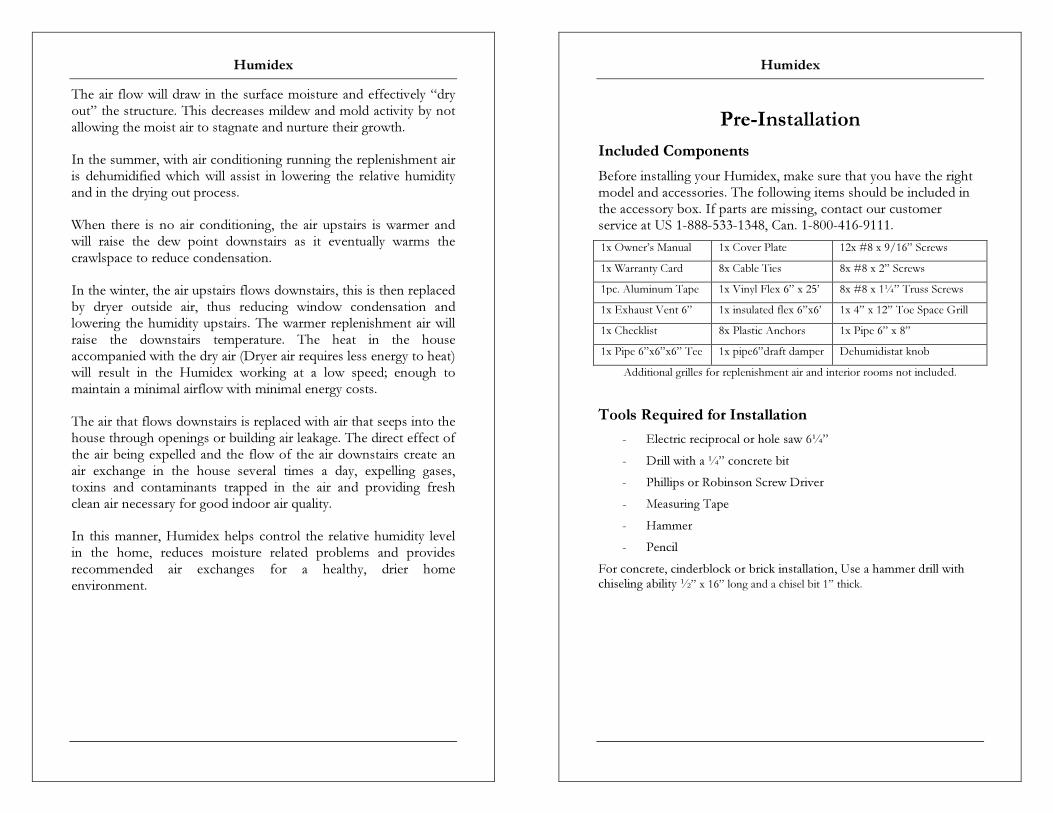
The air flow will draw in the surface moisture and effectively “dry out” the structure. This decreases mildew and mold activity by not allowing the moist air to stagnate and nurture their growth.
In the summer, with air conditioning running the replenishment air is dehumidified which will assist in lowering the relative humidity and in the drying out process.
When there is no air conditioning, the air upstairs is warmer and will raise the dew point downstairs as it eventually warms the crawlspace to reduce condensation.
In the winter, the air upstairs flows downstairs, this is then replaced by dryer outside air, thus reducing window condensation and lowering the humidity upstairs. The warmer replenishment air will raise the downstairs temperature. The heat in the house accompanied with the dry air (Dryer air requires less energy to heat) will result in the Humidex working at a low speed; enough to maintain a minimal airflow with minimal energy costs.
The air that flows downstairs is replaced with air that seeps into the house through openings or building air leakage. The direct effect of the air being expelled and the flow of the air downstairs create an air exchange in the house several times a day, expelling gases, toxins and contaminants trapped in the air and providing fresh clean air necessary for good indoor air quality.
In this manner, Humidex helps control the relative humidity level in the home, reduces moisture related problems and provides recommended air exchanges for a healthy, drier home environment.
Humidex
Pre-Installation
Included Components
Before installing your Humidex, make sure that you have the right model and accessories. The following items should be included in the accessory box. If parts are missing, contact our customer service at US 1-888-533-1348, Can. 1-800-416-9111.
1x Owner’s Manual 1x Cover Plate 12x #8 x 9/16” Screws
1x Warranty Card 8x Cable Ties 8x #8 x 2” Screws
1pc. Aluminum Tape 1x Vinyl Flex 6” x 25’ 8x #8 x 1¼” Truss Screws
1x Exhaust Vent 6” 1x insulated flex 6”x6’ 1x 4” x 12” Toe Space Grill
1x Checklist 8x Plastic Anchors 1x Pipe 6” x 8”
1x Pipe 6”x6”x6” Tee 1x pipe6”draft damper Dehumidistat knob
Additional grilles for replenishment air and interior rooms not included.
Tools Required for Installation
- Electric reciprocal or hole saw 6¼”
- Drill with a ¼” concrete bit
- Phillips or Robinson Screw Driver
- Measuring Tape
- Hammer
- Pencil
For concrete, cinderblock or brick installation, Use a hammer drill with chiseling ability ½” x 16” long and a chisel bit 1” thick.

Humidex
Key Installation Facts
1) Unit must be installed at floor level – approximately 3” off the floor.
2) Replenishment air has to flow from upstairs into the basement or crawlspace. Open doors that can be closed are not a substitute
for a properly installed vent.
3) Unit should be installed as far away as possible from the source of replenishment air.
4) Outside duct must be no less than 6” and dedicated for the Humidex unit only.
5) Maximum circulation is required to draw in air from all parts of the crawlspace.
6) Unit should not be installed within 8 feet of combustion appliance.
IMPORTANT – What Not to Do
1) DO NOT install the unit more than approx. 3 inches off the floor.
2) DO NOT make more than one turn with the duct and the ductwork should not be longer than 3 feet in total, unless rigid ducting is used - see ‘ducting” following.
3) DO NOT crush the vinyl Pipe. 4) DO NOT install the unit next to a replenishment air supply.
Warning!!!
Combustion Appliance Present in Dwelling Read this Section Carefully
With the presence of appliances evacuating air outside the building envelope (such as range hood, bathroom fan, dryer, Humidex, etc.) a negative pressure could be created inside the building. As the pressure inside the building gets lower than the barometric pressure outside, the smoke and gases from any combustion appliance (oil furnace, gas/wood stove, fireplace, etc.) may be drawn into the building rather than go out the chimney. This problem is usually curable by setting the controls of exhaust appliances, including the Humidex at less than maximum speed during the heating season (Note: when humidity conditions in the home are below the humidity setting on the Humidex, as they usually are during the heating season, the Humidex operates at
Humidex
Unit Operations
The Control Panel
- The switch will allow you to vary the rate of airflow. - The Knob allows you to select the desired humidity.
By default, you should set the fan speed on High and set the humidity control at the desired level, usually around 50%.
Note: For winter operation if there is still condensation on the windows when the humidity drops below 50%, lower the humidity control by a few percent (45-47%).
Make sure not to set it too low to ensure a healthy home since some people will be affected by dry conditions.
How a Humidex Work
Humidex is a mechanical ventilation appliance installed in the lowest level of a home, (basement or crawlspace), engineered to expel moisture-laden air that stagnates due to poor air circulation. Cool, moist air will gravitate to the lowest point of the home, which is the basement or crawlspace in a multi-level home and where it can condense on the cooler floor/wall surfaces. The lack of proper ventilation in the crawlspace creates an environment where the damp air will stagnate and emit odors, nurture the development of molds, mildew and saturate into the structure, i.e. walls, floors, frame works, drywall, as well as contents. A quiet powerful fan in the unit draws the moist surface air in through the bottom vents and then expels it out of the house through a 6 inch duct. The expelled air is replaced with a flow of fresh, dry, warmer replenishment air drawn downward from the upper level, which raises the temperature and lowers the relative humidity. The humidistat control in the unit measures the relative humidity of the air flowing out. When the humidity drops to below the set level, the unit will decrease the flow of air to a minimum.

Humidex
Humidex
approx. 25% of the capacity of a standard bathroom fan),or by introducing make-up air inside the building. A fresh air kit (Air Supply Ventilator) is available from your Humidex dealer, to help relieve the effects of negative air pressure in the building.
Ideal location of the Unit
- Air drawn in by Humidex pulls moisture off the surface floors and walls. To maximize the effectiveness;
A) Install unit in dampest, coolest and lowest part of crawlspace.
B) If possible, without hindering point “A”, install the Humidex as far away as possible from the source of replenishment air (i.e. stairwell) from upstairs or from replenishment air grill in crawl space area. This will allow for the unit to draw in the maximum moisture across the greatest surface distance before the upstairs replenishment air is pulled into the unit.
- Keep away from sources of excess heat (i.e. furnace room).
- Unit must be installed all the way down to floor level, in order to draw in the moisture. It should be approx. 3” and must not be higher than a max of 6 inches off floor level.
Note: Crawlspace models can be installed at up to 12” of the floor if extra height is required to properly install the unit.
- Keep at least 8 feet away from furnace or combustion appliance, to avoid interfering with airflow.
- The area (not less than 4 ft.) around the unit should be clear to allow the air to be pulled into the vents.

Humidex
Ducting
Unit comes in two sections that allow for flexibility in positioning the duct at the most convenient height. You can duct from the back of the unit, or from the top of the unit by removing the top cover. Duct can go through an outside wall, the floor joist or window. Duct should be vented above ground level to the outside or below ground into a window well that is open and not sealed off to the outdoors. The outside louver should be high enough to avoid infiltration of snow, flooding and rodents, etc. All necessary parts and outside louvers are included. In cases where the basement or crawlspace height clearance is too low, the top portion of the bottom section can be cut down by a maximum of 40 inches with a cutter, leaving the vents at the bottom intact, for a total minimum unit height of 62 inches. For extra high ceilings, an extension piece of 24 inches is available which can be added at the top of the unit. When ducting the unit outside, no more than 3 feet of Vinyl Flex should be used. When circumstances are that a longer span is required, rigid ducting can be used from the inside of the unit to the wall. The rigid duct will improve the airflow to compensate for the additional distance the air has to flow to reach the outside. When replacing a pane for a window installation, use pressurized wood or similar water/rot proof material. Make sure that no pipes, studs or wires are in the way. Duct has to be dedicated and not combined with any other existing ductwork in operation. Seal well around the outside opening.
Humidex

Humidex
Apply the four plastics anchors on the wall with the help of a hammer. Secure the Humidex to the wall using the four 1 ¼ inch screws provided.
Once the unit is properly installed, return outside, Apply exterior caulking, to the vent, to act as a weather seal.
NOTE: If high winds are often present in the location of the vent, they may cause a wind noise inside the house. If this is the case, an anti-gust hood (AGH-990) is available from your Humidex dealer.
Installing the CCC-103R
To allow the booster fan to draw air from the upper levels, a universal boot must be installed. First cut out a whole to fit the universal boot.
Mount CCC-103R booster fan on floor joist a minimum of 6’ away from the universal boot to reduce noise. Connect universal boot to booster fan with a 6” insulated flex.
If the building codes in your area require a backdraft damper to be installed, it must be placed on the exhaust side of the CCC-103R to limit the impact on the total airflow thru the unit
The CCC-103R booster fan must be plugged into the outlet located on the CCC-103E unit.
A T-junction duct and flex can be added to the exhaust side of the CCC-103R to direct air into all areas of the crawl space.
Humidex
Installation
Factors to consider
Following is a description of how to install the Humidex unit.
The installation must be done in the crawlspace or the lowest, dampest, coldest level of your dwelling. Try to find an outside wall to accommodate a 6¼” exit to the exterior of the house where no electrical wires or pipes are present Minimum distance to any source of heat should be 8 feet. Make sure that you do not install the unit in a boiler room.
Also maximize the distance between the unit and the source of replenishment air (example: stairwell or openings to upper level).
For Interior Wall Installation: The distance between the Humidex back and the exterior wall should not be more than 12 feet. For this application the flex has to be replaced with rigid piping. Optional: The bottom cap may be removed for added airflow.
Selecting the Duct Location
Now that you’ve decided where to install the unit, you must select a location for a 6¼” duct hole in the outside wall. This hole is needed to pass a duct through the outside wall. Make sure that the hole location is above ground level. Also make sure that the hole doesn’t line up with a stud, electrical wires, or pipe. For models UNS-209 and HDS-209, which are adjustable in height, the hole is in the box/rim joist between the floor joists of the crawlspace ceiling, or through the wall.

Humidex
Preparing the CCC-103E for Installation
Measure the required Unit height. Remember that the units cannot be higher than 3” to 6” off the ground.
From the inside, drill a pilot hole of approximately ¼” at the center of the proposed 6¼” hole.
Outside the building, find the pilot hole. Using a hole-saw, with the pilot hole as a guide, drill a 6¼” hole.
Brick or Concrete Wall: There are two ways of going through brick or concrete. The first method consists of using a hammer drill. Make holes (approximately 5/8”) with the hammer drill 1” apart through the brick in a circular shape outlining the 6 ¼” hole. Finish cutting the outer edge of the hole using a chisel. If a hammer drill is not available, a chisel can be used. As brick is brittle chiseling from the center of the pilot hole will chip the brick easily. Continue chiseling until you reach the outer edge of the 6 ¼” hole.
Attaching the Flex, Pipe and Vent
Attach the vent to the 6” pipe with the ½ in screws provided.
Attach the flex to the 6” pipe with 24” tie wrap.
Humidex
From the outside, slide the pipe through the 6 ¼” hole. Insert four 2 inch screws to secure vent to the outside wall.
Make sure the vent is not twisted by inserting the screws too tight and that the flaps are working properly.
From the inside measure the distance between the elbow and the flex. Cut off the excess flex. If this is not done, the efficiency of the unit will diminish drastically.
Fasten Unit to the Wall
Now that the flex is tight, it can be attached to the elbow with the tie wrap. Flex should not be kinked in any way.
Leaving a 1 inch gap between the top of the unit and the ceiling (In case of a finished ceiling, leave a 1/8 inch gap between the top of the unit and the ceiling avoiding any contact between the two) drill ¼” pilot holes through the lips of the unit and the wall.