Installation & Owner’s Manual - humidex.com · For HCS-BS Only ... service at US 1-888-533-1348,...
24
January 2018 Humidex HCS Rev 1.6En Installation & Owner’s Manual English This Manual Covers the Following Models HCS-BS-HDEX HCS-CS-HDEX Manufactured by: ClairiTech Innovations Inc. 1095 Ohio Rd. Boudreau-Ouest, NB Canada E4P 6N4
Transcript of Installation & Owner’s Manual - humidex.com · For HCS-BS Only ... service at US 1-888-533-1348,...

January 2018 Humidex HCS Rev 1.6En
Installation & Owner’s Manual
English
This Manual Covers the Following Models
HCS-BS-HDEX
HCS-CS-HDEX
Manufactured by: ClairiTech Innovations Inc.
1095 Ohio Rd. Boudreau-Ouest, NB
Canada E4P 6N4

Humidex
1
Table of Contents
Table of Contents ...................................................................................................................... 1
Service and Warranty ................................................................................................................. 3
FOR CUSTOMER ASSISTANCE ......................................................................................................................... 3
CONSUMER LIMITED WARRANTY ................................................................................................................. 4
PRE-INSTALLATION ......................................................................................................................................... 5
INCLUDED COMPONENTS .............................................................................................................................. 5
TOOLS REQUIRED FOR INSTALLATION ........................................................................................................ 5
KEY INSTALLATION FACTS ............................................................................................................................ 5
IMPORTANT – WHAT NOT TO DO ........................................................................................................... 5
DO NOT MAKE MORE THAN ONE TURN WITH THE DUCT AND THE DUCTWORK SHOULD NOT BE LONGER THAN 3 FEET IN TOTAL, UNLESS RIGID DUCTING IS USED - SEE ‘ ERROR! BOOKMARK NOT DEFINED.
COMBUSTION APPLIANCE PRESENT IN DWELLING ................................................................................... 6
IDEAL LOCATION OF THE UNIT .................................................................................................................... 6
REPLENISHMENT AIR TO BASEMENT FROM UPSTAIRS ............................................................................... 7
DUCTING .......................................................................................................................................................... 7
Installation ................................................................................................................................. 8
FACTORS TO CONSIDER .................................................................................................................................. 8
SELECTING THE DUCT LOCATION ............................................................................................................... 8
PREPARING THE HUMIDEX FOR INSTALLATION ........................................................................................ 9
PUTTING THE UNIT TOGETHER ..................................................................................................................10
For HCS-BS Only ........................................................................................................................................10

Humidex
2
FASTEN THE UNIT TO THE WALL .................................................................................................................11
ATTACHING THE FLEX AND OUTSIDE VENT ...........................................................................................12
WIRING AND ATTACHING THE CONTROL ................................................................................................12
Unit Operations ....................................................................................................................... 15
THE FIRST TIME THE UNIT RUNS… .............................................................................................................15
VACANT HOMES ............................................................................................................................................15
MAINTAINING YOUR HCS ...........................................................................................................................15
What is the dew point? ............................................................................................................ 16
NEW INSTALLATIONS IN THE SUMMER ......................................................................................................16
LCD Display and Control Layout ........................................................................................... 17
THE LCD DISPLAY .......................................................................................................................................18
NAVIGATING THE LCD MENU ...................................................................................................................18
ENTERING THE MAIN MENU ......................................................................................................................19
RELATIVE HUMIDITY MENU .......................................................................................................................19
OVERRIDE TIMER MENU .............................................................................................................................20
CHANGING FAN SPEEDS ..............................................................................................................................20
NOTES ON LCD DISPLAY FEATURES ..........................................................................................................21
Most Common Issues .............................................................................................................. 22
MOLD, MILDEW AND MUSTY SMELL ..........................................................................................................22
Specifications ........................................................................................................................... 23
TECHNICAL DATA .........................................................................................................................................23
DIMENSIONS ..................................................................................................................................................23

Humidex
3
Service and Warranty
For Customer Assistance
To aid in answering questions if you call for service or warranty purposes, please record below the model and serial number located on the side of the unit.
Product Name:
Model #:
Date of Manufacturing:
Date of Purchase:
Serial #:
Dealer Name (If Any):
Please Note the above information before contacting us.
IMPORTANT
To properly validate your warranty, you must fill out and return the warranty card as soon as possible. If your unit is not registered, a proof of purchase will be necessary should it require any services. You can also register your warranty online http://www.clairitech.com/warranty .
For the Following Inquiries:
- Service - Parts - Accessories - Additional Customer Information
Please contact us by: Phone: 1-888-533-1348 Email: [email protected] Website: www.humidex.ca
Humidex
4
Consumer Limited Warranty
ClairiTech Innovations Inc. warrants to the first consumer that this product, when shipped in its original container, will be free from defective workmanship and materials, and agrees that it will, at its discretion, either repair the defect or replace the defective Product or part thereof with a new or remanufactured equivalent at no charge to the purchaser for the period(s) set forth below. The defective part must be returned to the manufacturer ClairiTech Innovations Inc. All transportation charges are the sole responsibility of the purchaser. This warranty does not apply to any appearance items of the product nor to the additional excluded item(s) set forth below of which have been damaged, defaced, subjected to improper voltage, abnormal service or handling, or which has been altered or modified in design or construction. In order to enforce the rights under this limited warranty, the purchaser must fill out and return the warranty card as soon as possible. If your unit is not registered, a proof of purchase will be necessary should it require any services. Neither the sales personnel of the seller nor any other person is authorized to make any warranties other than those described herein, or to extend the duration of any warranties beyond the time period described herein on behalf of ClairiTech Innovations Inc. The warranties described herein shall be the sole and exclusive warranties granted by ClairiTech and shall be the sole and exclusive remedy available to the purchaser. Correction of defects, in the manner and for the period of time described herein, shall constitute complete fulfillment of all liabilities and responsibilities of ClairiTech to the purchaser with respect to the Product, and shall constitute full satisfaction of all claims, whether based on contract, negligence, and strict liability or otherwise. In no event shall ClairiTech be liable, or in any way responsible, for any damages or defects in the Product which were caused by repairs or attempted repairs performed by anyone other than an authorized servicer, unless approved by ClairiTech in writing. Nor shall ClairiTech be liable or in any way responsible for any incidental or consequential economic or property damage.
Warranty Period for this product:
Ten (10) years on all mechanical parts and on cabinet. Five (5) years on all electrical components (excluding the control unit) Two (2) years on the LCD control unit
Additional Items Excluded from Warranty Coverage (If Any):
Appearance items of the product, Exterior vent and any printed material.
Where to obtain service: From the Manufacturer. (Refer to Page 3)
This warranty is non-transferable and applies to residential use only.
To obtain supply, accessory or product information, contact us.
Humidex
5
Refer to Page 3 for Contact Information.
Pre-Installation
Included Components
Before installing your Humidex, make sure that you have the right model and accessories. The following items should be included in the accessory box. If parts are missing, contact our customer service at US 1-888-533-1348, Can. 1-800-416-9111.
1x Owner’s Manual 2x Cable Ties 1x Green Connector 1x Warranty Card 1x Cover plate 1x Aluminum tape 1x Vinyl Flex 6” x 24” 4x Plastic Anchors 4x Truss screws #8 x1 1/4 1x Exhaust Vent 6” 4x #8 x 2” Screws 1x White wire (50 ft.) 1x Checklist 6x #8 x 1/2” Screws
Additional grilles for replenishment air and interior rooms not included. Tools Required for Installation
- Electric reciprocal or hole saw 6¼” - Drill with a ¼” concrete bit - Phillips or Robinson Screw Driver - Measuring Tape - Hammer - Pencil
For concrete, cinderblock or brick installation, use a hammer drill with chiseling ability ½” x 16” long and a chisel bit 1” thick.
Key Installation Facts 1) Unit must be installed at floor level – approximately 3” off the floor. 2) Replenishment air has to flow from upstairs into the basement or crawlspace. Open doors
that can be closed are not a substitute for a properly installed vent. 3) Unit should be installed as far away as possible from the source of replenishment air. 4) Outside duct must be no less than 6” and dedicated for the HCS-BS or HCS-CS Unit only. 5) Maximum circulation is required to draw in air from all parts of the basement. * 6) Unit should not be installed within 8 feet of combustion appliance.
IMPORTANT – What Not to Do 1) DO NOT install the unit more than approx. 3 inches off the floor. 2) DO NOT make more than one turn with the duct and the ductwork should not be longer than 3
feet in total, unless rigid ducting is used - see “Ducting”, Page 7 3) DO NOT crush the vinyl Pipe. 4) DO NOT install the unit next to a replenishment air supply. 5) DO NOT install the unit within 8 feet of a heat source (Radiator, heater, etc…)
Warning!!!
Humidex
6
Combustion Appliance Present in Dwelling Read this Section Carefully
With the presence of appliances evacuating air outside the building envelope (such as range hood, bathroom fan, dryer, Humidex, etc.) a negative pressure could be created inside the building. As the pressure inside the building gets lower than the barometric pressure outside, the smoke and gases from any combustion appliance (oil furnace, gas/wood stove, fireplace, etc.) may be drawn into the building rather than go out the chimney. This problem is usually curable by setting the controls of exhaust appliances, including the Humidex at less than maximum speed during the heating season (Note: when humidity conditions in the home are below the humidity setting on the Humidex, as they usually are during the heating season, the Humidex operates at approx. 25% of the capacity of a standard bathroom fan), or by introducing make-up air inside the building. A fresh air kit (Air Supply Ventilator) is available from your Humidex dealer, to help relieve the effects of negative air pressure in the building.
Ideal location of the Unit
- Air drawn in by Humidex pulls moisture off the surface floors and walls. To maximize the effectiveness;
A) Install unit in dampest, coolest and lowest part of basement. B) If possible, without hindering point “A”, install the Humidex as far away as possible from
the source of replenishment air (i.e. stairwell) from upstairs or from replenishment air grill in crawl space area. This will allow for the unit to draw in the maximum moisture across the greatest surface distance before the upstairs replenishment air is pulled into the unit.
- Keep away from sources of excess heat (i.e. furnace room).
- Unit must be installed all the way down to floor level, in order to draw in the moisture. It should be approx. 3” and must not be higher than a max of 6” off floor level.
- Keep at least 8 feet away from furnace or combustion appliance to reduce risk of interference
- The area within a radius of 4 feet around the unit should be clear to allow the air to be pulled into the vents.
Humidex
7
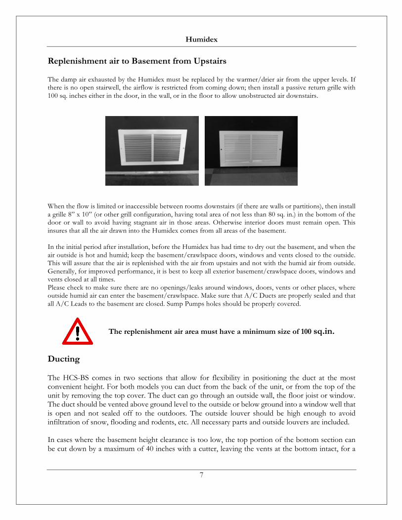
Replenishment air to Basement from Upstairs
The damp air exhausted by the Humidex must be replaced by the warmer/drier air from the upper levels. If there is no open stairwell, the airflow is restricted from coming down; then install a passive return grille with 100 sq. inches either in the door, in the wall, or in the floor to allow unobstructed air downstairs.
When the flow is limited or inaccessible between rooms downstairs (if there are walls or partitions), then install a grille 8” x 10” (or other grill configuration, having total area of not less than 80 sq. in.) in the bottom of the door or wall to avoid having stagnant air in those areas. Otherwise interior doors must remain open. This insures that all the air drawn into the Humidex comes from all areas of the basement. In the initial period after installation, before the Humidex has had time to dry out the basement, and when the air outside is hot and humid; keep the basement/crawlspace doors, windows and vents closed to the outside. This will assure that the air is replenished with the air from upstairs and not with the humid air from outside. Generally, for improved performance, it is best to keep all exterior basement/crawlspace doors, windows and vents closed at all times. Please check to make sure there are no openings/leaks around windows, doors, vents or other places, where outside humid air can enter the basement/crawlspace. Make sure that A/C Ducts are properly sealed and that all A/C Leads to the basement are closed. Sump Pumps holes should be properly covered.
Ducting
The HCS-BS comes in two sections that allow for flexibility in positioning the duct at the most convenient height. For both models you can duct from the back of the unit, or from the top of the unit by removing the top cover. The duct can go through an outside wall, the floor joist or window. The duct should be vented above ground level to the outside or below ground into a window well that is open and not sealed off to the outdoors. The outside louver should be high enough to avoid infiltration of snow, flooding and rodents, etc. All necessary parts and outside louvers are included. In cases where the basement height clearance is too low, the top portion of the bottom section can be cut down by a maximum of 40 inches with a cutter, leaving the vents at the bottom intact, for a
The replenishment air area must have a minimum size of 100 sq.in.
Humidex
8
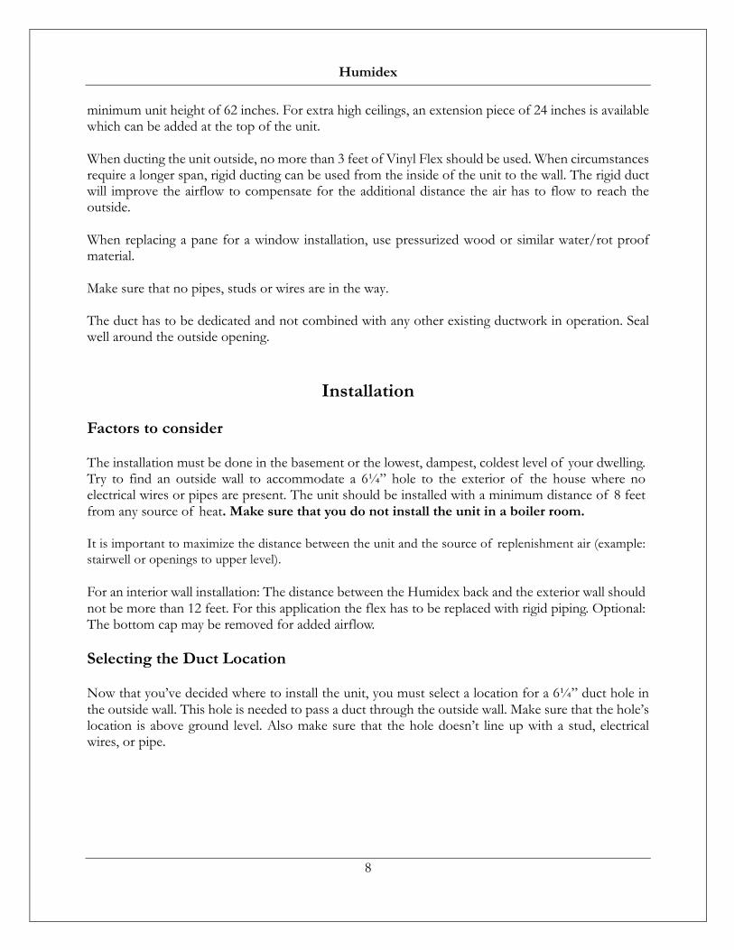
minimum unit height of 62 inches. For extra high ceilings, an extension piece of 24 inches is available which can be added at the top of the unit. When ducting the unit outside, no more than 3 feet of Vinyl Flex should be used. When circumstances require a longer span, rigid ducting can be used from the inside of the unit to the wall. The rigid duct will improve the airflow to compensate for the additional distance the air has to flow to reach the outside. When replacing a pane for a window installation, use pressurized wood or similar water/rot proof material. Make sure that no pipes, studs or wires are in the way. The duct has to be dedicated and not combined with any other existing ductwork in operation. Seal well around the outside opening.
Installation
Factors to consider
The installation must be done in the basement or the lowest, dampest, coldest level of your dwelling. Try to find an outside wall to accommodate a 6¼” hole to the exterior of the house where no electrical wires or pipes are present. The unit should be installed with a minimum distance of 8 feet from any source of heat. Make sure that you do not install the unit in a boiler room.
It is important to maximize the distance between the unit and the source of replenishment air (example: stairwell or openings to upper level).
For an interior wall installation: The distance between the Humidex back and the exterior wall should not be more than 12 feet. For this application the flex has to be replaced with rigid piping. Optional: The bottom cap may be removed for added airflow.
Selecting the Duct Location
Now that you’ve decided where to install the unit, you must select a location for a 6¼” duct hole in the outside wall. This hole is needed to pass a duct through the outside wall. Make sure that the hole’s location is above ground level. Also make sure that the hole doesn’t line up with a stud, electrical wires, or pipe.

Humidex
9
Preparing the Humidex for Installation
Now that an installation location has been chosen a hole must be made for the vent. Start by measuring the required Unit height and mark the location of the hole. Remember that the units cannot be higher than 3” to 6” off the ground.
From the inside, drill a pilot hole of approximately ¼” wide at the center of the proposed 6¼” hole.
Outside the building, find the pilot hole.
Now using a hole-saw, with the pilot hole as a guide, drill a 6¼” hole.
Brick or Concrete Wall: There are two ways of going through brick or concrete. The first method consists of using a hammer drill. Make holes (approximately 5/8”) with the hammer drill 1” apart through the brick in a circular shape outlining the 6 ¼” hole. Finish cutting the outer edge of the hole using a chisel. If a hammer drill is not available, a chisel can be used. As brick is brittle chiseling from the center of the pilot hole will chip the brick easily. Continue chiseling until you reach the outer edge of the 6 ¼” hole.

Humidex
10
Putting the unit together
For HCS-BS Only
Join the two halves (Bottom section must fit inside Top section) of the HCS-BS casing together, overlapping the two pieces such as the desired height is obtained. Remove screws if necessary.
NOTE: If the unit has to be shorter than 85” cut the top of the bottom part.
Secure the two halves together using ½” metal fastening screws.
A cover plate can be used to close the gap between both halves if necessary. Using aluminum tape or duct tape seal the seam in the back where the two halves join together.
Note: When installing the optional 24” extension, remove top cap and straighten the 90° elbow. Use the 6” galvanized pipe to extend the length needed. Cut the pipe to the proper length before snapping it together. Attach the top cap to the extension cover with the 4 screws provided. Add exterior cover to the base and fasten securely with the provided screws.

Humidex
11
Fasten the unit to the wall
With the help of a tie wrap attach the flex pipe to the collar on the back of the unit before attaching the unit to the wall. Insert the other end of the flex pipe inside the hole in the wall.
(a few Small 9/16” Screw can be used to affix the flex to the mount)
Leaving a 1-inch gap between the top of the unit and the ceiling, drill ¼” pilot holes through the lips of the unit and the wall.
Apply the four plastics anchors on the wall with the help of a hammer. Secure the HCS-BS or HCS-CS Unit to the wall using the four 1 ¼ inch screws provided.

Humidex
12
Attaching the Flex and Outside Vent
From the outside, pull the flex pipe through the 6 ¼” hole. Attach the vent to the 6” flex with the ½ in screws provided.
Insert four 2 inch screws to secure the vent to the outside wall. Make sure the vent is not twisted by inserting the screws too tight and that the flaps are working properly.
NOTE: If high winds are often present in the location of the vent, they may cause a wind noise inside the house. If this is the case, an anti-gust hood (AGH-990) is available from your Humidex dealer.
Wiring and Attaching the Control
Once the exhaust unit has been mounted, the control needs to be installed and connected. It is crucial that the control is placed in the proper location. The HCS control must be installed on the main floor and as close to the source of the replenishment air as possible while trying to stay away from exterior doors and windows.
After having selected the installation location, the provided wire must be run from the main unit to the control location.
Humidex
13
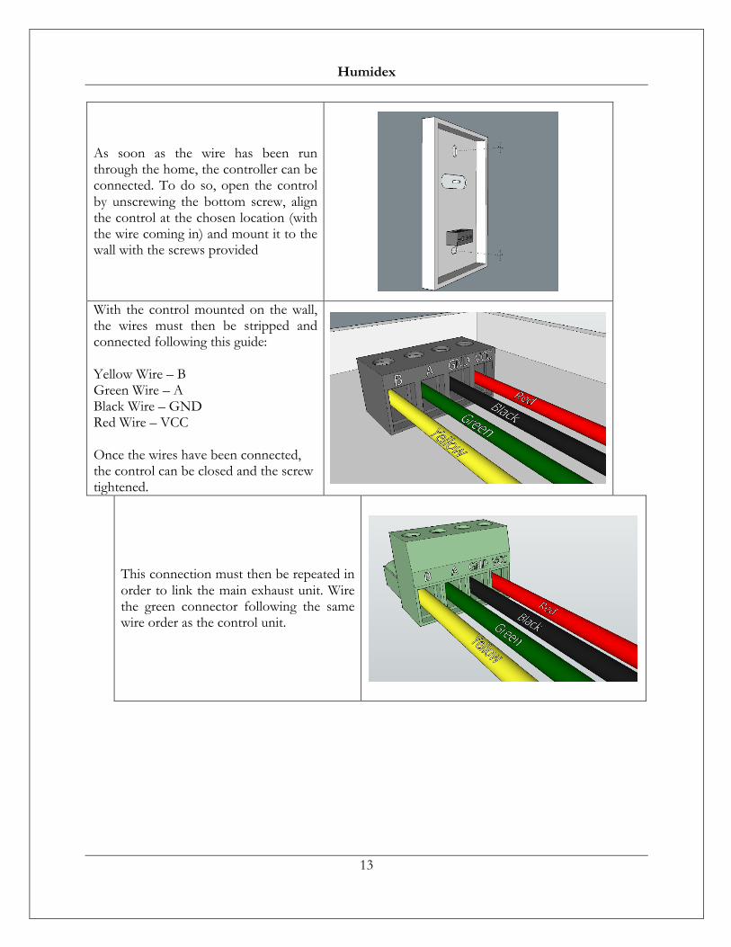
As soon as the wire has been run through the home, the controller can be connected. To do so, open the control by unscrewing the bottom screw, align the control at the chosen location (with the wire coming in) and mount it to the wall with the screws provided
With the control mounted on the wall, the wires must then be stripped and connected following this guide: Yellow Wire – B Green Wire – A Black Wire – GND Red Wire – VCC Once the wires have been connected, the control can be closed and the screw tightened.
This connection must then be repeated in order to link the main exhaust unit. Wire the green connector following the same wire order as the control unit.

Humidex
14
Now that the connecter has been wired, insert it into the main exhaust unit.
Now that the control has been installed and connected to the main exhaust unit, the HCS can be plugged into any 115V outlet. Note: A grounded extension cord with a maximum length of 10 feet may be used if necessary.

Humidex
15
Unit Operations
The first time the unit runs…
When the unit is first turned on, it will run at medium speed for 6 hours. During this initial 6-hour period, it is important to allow it to run uninterrupted, since the unit will take readings that will be important to determine the best operating speed that will, over time, get the most energy efficient ventilation for the entire home and maximum reduction of relative humidity.
The HCS-BS and HCS-CS are pre-programmed to a default humidity setting of 55% which will result in the best operation all year round.
After power outages or whenever the unit is powered down (unplugged) and powered up again (plugged into the wall again), the unit reads the last recorded settings and will return to its regular operation mode.
Note: For the unit to function properly and to allow the unit to provide the best energy efficient ventilation and humidity control, all windows, doors with access to the outdoor and vents to the outdoor should be closed to prevent an excessive amount of outdoor air from entering directly into the house.
Vacant Homes
Performance results are maximized when the building is occupied. If home is vacant for a prolonged period of time, then the unit should be set to operate at low speed. A fresh air intake supply is recommended via a small opening in a window upstairs or a supply vent such as the ASV-90.
Maintaining your HCS
The HCS Products do not require any internal maintenance. The only maintenance needed for your HCS is a periodic vacuuming of the dust accumulation at the intake grilles or louvers located at the bottom of the unit. For proper functionality do not store anything within a radius of 4 feet around the base of the Humidex.

Humidex
16
What is the dew point?
The dew point is one of the three environmental variables that are important when discussing the conditions in your home. Understanding the dew point will help you understand how the HCS unit operates and how it will help to reduce the relative humidity (RH%) level infiltrating your home and eliminate excess humidity, while providing energy efficient ventilation for your home. The dew point is defined as the temperature at which the water vapor contained in a given volume of air will condense into water. This is best illustrated by an example: Assume the following measurements are taken by the unit: Temperature = 68⁰F Relative Humidity = 60% Using the temperature and RH% values measured, we would calculate that the dew point in your home is 54⁰F. As the temperature of surfaces in your dwelling (these tend to reflect the floor temperature, which is generally cooler than the ceiling air temperature) approaches the value of the dew point, you risk having condensation on those colder surfaces (as well as un-insulated water pipes). This condensation can lead to problem situations that might produce unhealthy living conditions in your home (odors, molds, etc.)
New Installations in the Summer
The late spring and early/mid-summertime temperature in most basements remains at approximately 59° to 66° F (15° to 19° C) whereas the air entering the basement from the upstairs of the house will generally be in the range of 75° to 85° F (24° to 29° C) with a relative humidity of 70 to 75%. This air will have a dew point (the temperature of surfaces on which it will condense, including basement surfaces) in the range of 64° to 76° F (18° to 24°). When a Humidex is installed in these conditions, condensation may result, as the air from the upstairs comes in contact with cold surfaces (i.e. concrete walls, floors, etc). The Humidex ventilation effect will over time increase the basement temperature and help prevent this condition, however, during the initial operating season; a small amount of heat may have to be added temporarily to the basement to increase its temperature. If this condition occurs also reduce speed exhaust to medium. If an air conditioner is present in the house, close all AC vents/leads/ducts to the basement.
COLD SURFACE FACTS – IMPORTANT It is recommended that any exposed cold water pipes and A/C ducts should be insulated to reduce condensation on these cold surfaces before a humidex is installed.

Humidex
17
LCD Display and Control Layout
The following sections of this operating manual refer to the user interface presented below:
The user interface consists of:
1- LCD Display 2- Up Arrow Button 3- Down Arrow Button 4- Cancel Button 5- Ok Button
1
2
3
4
5
Humidex
18
The LCD Display
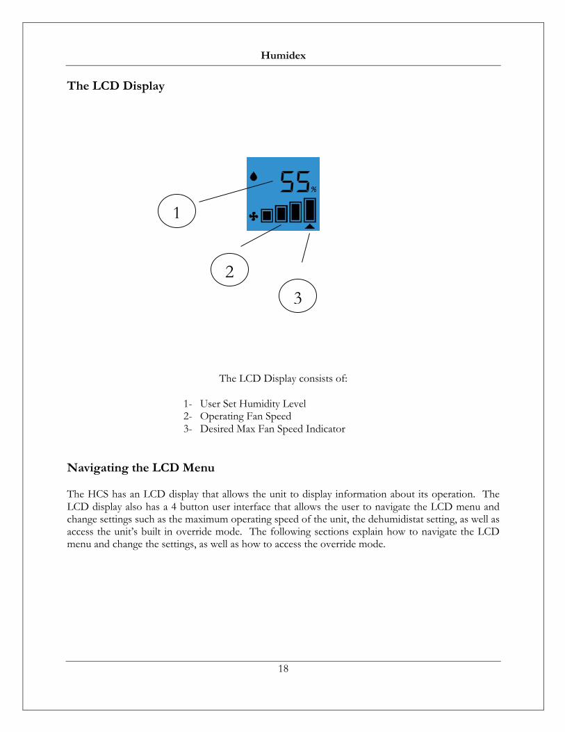
The LCD Display consists of:
1- User Set Humidity Level 2- Operating Fan Speed 3- Desired Max Fan Speed Indicator
Navigating the LCD Menu
The HCS has an LCD display that allows the unit to display information about its operation. The LCD display also has a 4 button user interface that allows the user to navigate the LCD menu and change settings such as the maximum operating speed of the unit, the dehumidistat setting, as well as access the unit’s built in override mode. The following sections explain how to navigate the LCD menu and change the settings, as well as how to access the override mode.
1
2 3

Humidex
19
Entering the Main Menu To change any settings for the HCS, you must first enter the main menu. To do so simply press the up arrow and cancel button at the same time.
Once inside the main menu, the arrows keys can be used to cycle through the relative humidity menu, override menu and fan speed menu. The blinking icon will allow you to know which section you’re looking at (Red icons are blinking icons).
To select one of these menus, press the Ok button. To return to the main screen press the cancel button.
Relative Humidity Menu Once the relative humidity menu has been selected, the screen will change in order to allow the user to change the desired humidity level. Using the arrows keys will allow you to increase or decrease the desired RH value in increments of 5%. To accept a new value, select OK Button or the Cancel button to return to the main menu. If the wrong level is entered, repeat this procedure.
** Recommended humidity level for summer season is 55% and 45% for the winter season. Please note this does not show current humidity level, but rather the desired humidity level.
Relative Humidity Menu Override Menu Fan Speed Menu

Humidex
20
Override Timer Menu The override function allows you to provide maximum ventilation for a predetermined amount of time, regardless of the fan speed chosen by the computerized/sensor control, to alleviate certain conditions such as fumes from new paint, flooring, furniture or excess moisture from hot showers, cooking, etc. To set an override timer, the override menu must be selected. Once this is done the following screen will be displayed. Use the Up/Down Arrow Buttons to cycle through the different override timer options and once the desired override time is chosen, press the Ok Button to begin the override or the Cancel button to return to the main menu. If the wrong time is entered, repeat this procedure.
Changing Fan Speeds
To change the maximum fan speeds, simply select the fan speed menu from the main menu. Once the display has changed to the Fan speed menu screen, you can use the Up/Down Arrow Buttons to cycle through all of the different fan speeds and then you can select the speed by pressing the Ok Button or the Cancel button to return to the main menu. If the wrong speed is entered, repeat this procedure.

Humidex
21
Maximum Operating Speed Airflow (CFM)
HCS-BS HCS-CS
High 230 Intermediate 150
Medium 90 Low1/Low2 35/65
*Thesespeedsmayvarydependingoninstallation
The solid bars will denote the actual speed at which the fan is operating, the arrow below denotes the maximum chosen setting.
** Please note the unit will not exceed the maximum user set fan speed, unless the override mode is running. The control will choose the proper fan speed depending on humidity, temperature and dew point conditions.
Notes on LCD display features
1) The LCD display on this unit has a built in backlight to allow for better readability in darker locations. This backlight turns on when any button on the control panel is pressed and turns off after no button has been pressed on the unit for a period of 10 seconds.
2) The unit is fully automatic once set, requiring adjustments only if you wish to change the settings.

Humidex
22
Most Common Issues
Mold, Mildew and Musty Smell
If mold or mildew is present prior to installing a Humidex, please have the contaminated area cleaned. Not doing so could cause the Humidex to spread that mold to other locations in the basement or crawlspace.
To avoid Mold, Mildew or Musty Smells:
- Follow the Recommendations on Page 15 (Concerning New Installations in the summer).
To ensure the proper functionality of the Humidex:
- Verify that the replenishment air is flowing from the upstairs to the downstairs. - Increase ventilation in remote areas with a portable fan. - Any exposed pipes and ducts should be insulated. - Cinder block basement walls should be sealed with plastic vapor barrier or sealant. - Dirt floor in crawl space or basement should be covered with vapor barrier. - Sump pump should be equipped with a cover. - Rainwater from the roof should be directed away from the basement or foundation. - Landscaping should slope away from foundations. - Insulating basement will reduce the condensation and also reduce the energy cost during
heating season.
Do not attempt to service the Humidex yourself. If you are not sure about certain functions, please refer to Page 3.

Humidex
23
Specifications
Technical Data
Model Amps (A)
Watts (W)
Airflow (CFM)
Capacity (Sq.Ft.)
HCS-BS-HDEX 0.30 34 230 2,400 HCS-CS-HDEX 0.30 34 230 3,000
All Units require a 115 VAC electrical outlet
Dimensions
Model Height (In.) Width (In.) Depth (In.) HCS-BS-HDEX *85 - 96” 11.5” 8.5” HCS-CS-HDEX *32” 11.5” 8.5”
*A 24 Inch extension section is available if extra height is required