Installation & Operation Manual - · PDF fileInstallation & Operation Manual ......
12
Installation & Operation Manual This IOM is for the following ProMation Engineering Products: P1-120N4-RO P1-120N4-RC P1-230N4-RO P1-230N4-RC P1-12N4-AC-RO P1-12N4-DC-RO P1-12N4-AC-RC P1-12N4-DC-RC P1-24N4-AC-RO P1-24N4-DC-RO P1-24N4-AC-RC P1-24N4-DC-RC
Transcript of Installation & Operation Manual - · PDF fileInstallation & Operation Manual ......
Installation & Operation Manual
This IOM is for the following ProMation Engineering Products:
P1-120N4-ROP1-120N4-RCP1-230N4-ROP1-230N4-RC
P1-12N4-AC-ROP1-12N4-DC-ROP1-12N4-AC-RCP1-12N4-DC-RCP1-24N4-AC-ROP1-24N4-DC-ROP1-24N4-AC-RCP1-24N4-DC-RC

This page intentionally left blank
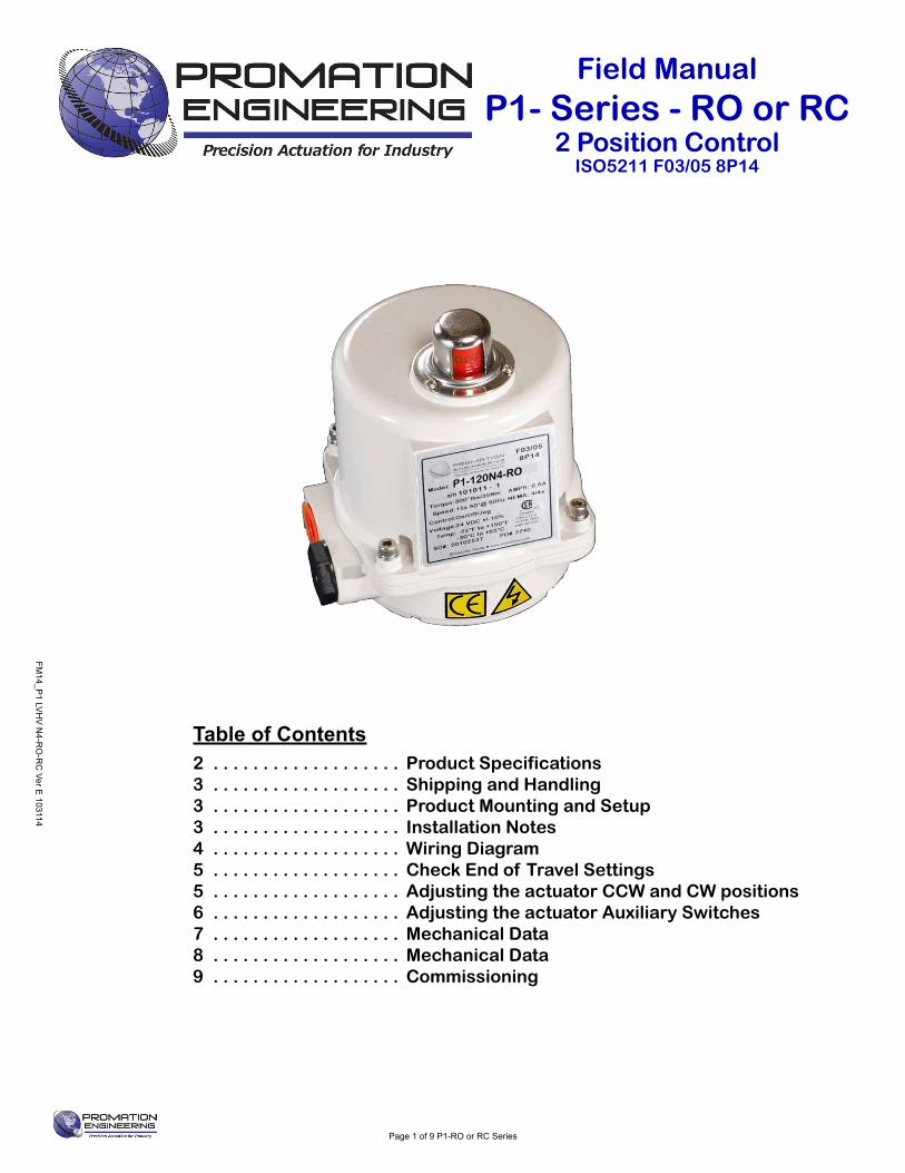
Table of Contents2 . . . . . . . . . . . . . . . . . . . Product Specifications3 . . . . . . . . . . . . . . . . . . . Shipping and Handling3 . . . . . . . . . . . . . . . . . . . Product Mounting and Setup3 . . . . . . . . . . . . . . . . . . . Installation Notes4 . . . . . . . . . . . . . . . . . . . Wiring Diagram5 . . . . . . . . . . . . . . . . . . . Check End of Travel Settings5 . . . . . . . . . . . . . . . . . . . Adjusting the actuator CCW and CW positions6 . . . . . . . . . . . . . . . . . . . Adjusting the actuator Auxiliary Switches7 . . . . . . . . . . . . . . . . . . . Mechanical Data8 . . . . . . . . . . . . . . . . . . . Mechanical Data9 . . . . . . . . . . . . . . . . . . . Commissioning
FM14_P
1 LVH
V N
4-RO
-RC
Ver E 103114
Page 1 of 9 P1-RO or RC Series
Field ManualP1- Series - RO or RC
2 Position ControlISO5211 F03/05 8P14
P1-120N4-RO
IntroductionThis document provides necessary information for set-up, calibration, testing and use of the P Series quarter-turn electric actuators stated on the cover page. Each unit is shipped from the factory with initial calibration of mechanical stops, cams and switches completed for 0-90 degree operation. However, these are general settings and serve as a starting point for proper calibration of the actuator in its real-world application.
SafetySafety is a basic factor any time you maintain and operate mechanical equipment. Appropriate handling methods and proper use of tools and clothes can help prevent serious accidents -- accidents which can cause injuries to you or a fellow worker. This manual was created to enable a trained user to install, adjust and troubleshoot your ProMation actuator.
Only competent and trained personnel should install, maintain and operate ProMation Actuators. Any work related to this actuator must be carried out in accordance with this manual and related codes and regulations. Local workplace health and safety rules should always be followed.
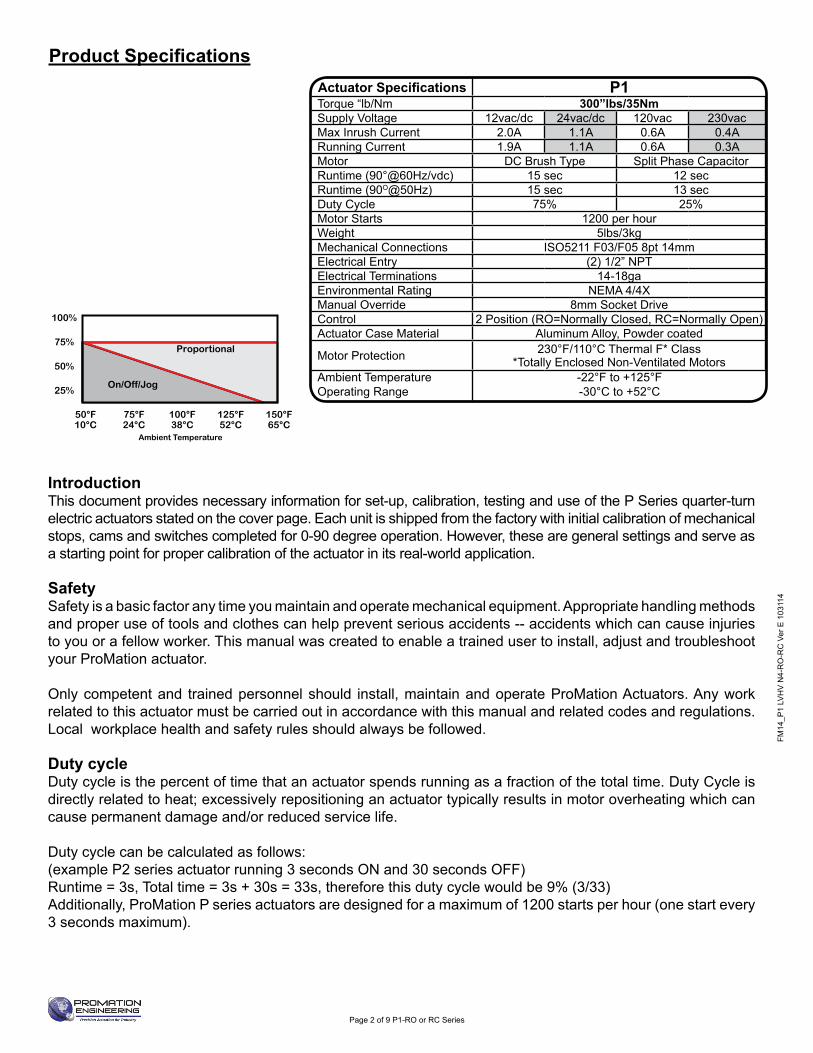
Duty cycle Duty cycle is the percent of time that an actuator spends running as a fraction of the total time. Duty Cycle is directly related to heat; excessively repositioning an actuator typically results in motor overheating which can cause permanent damage and/or reduced service life.
Duty cycle can be calculated as follows: (example P2 series actuator running 3 seconds ON and 30 seconds OFF)Runtime = 3s, Total time = 3s + 30s = 33s, therefore this duty cycle would be 9% (3/33)Additionally, ProMation P series actuators are designed for a maximum of 1200 starts per hour (one start every 3 seconds maximum).
50°F10°C
75°F24°C
100°F38°C
125°F52°C
150°F65°C
25%
50%
75%
100%
On/Off/Jog
Proportional
Ambient Temperature
FM14
_P1
LVH
V N
4-R
O-R
C V
er E
103
114
Page 2 of 9 P1-RO or RC Series
Product SpecificationsActuator Specifications P1Torque “lb/Nm 300”lbs/35NmSupply Voltage 12vac/dc 24vac/dc 120vac 230vacMax Inrush Current 2.0A 1.1A 0.6A 0.4ARunning Current 1.9A 1.1A 0.6A 0.3AMotor DC Brush Type Split Phase CapacitorRuntime (90°@60Hz/vdc) 15 sec 12 secRuntime (90O@50Hz) 15 sec 13 secDuty Cycle 75% 25%Motor Starts 1200 per hourWeight 5lbs/3kgMechanical Connections ISO5211 F03/F05 8pt 14mmElectrical Entry (2) 1/2” NPTElectrical Terminations 14-18gaEnvironmental Rating NEMA 4/4XManual Override 8mm Socket DriveControl 2 Position (RO=Normally Closed, RC=Normally Open)Actuator Case Material Aluminum Alloy, Powder coated
Motor Protection 230°F/110°C Thermal F* Class*Totally Enclosed Non-Ventilated Motors
Ambient Temperature Operating Range
-22°F to +125°F-30°C to +52°C
FM14_P
1 LVH
V N
4-RO
-RC
Ver E 103114
Page 3 of 9 P1-RO or RC Series
Product Mounting and Setup1. Note: This design utilizes NO MECHANICAL stops. It is recommended that
you do NOT use the manual override until the actuator is mounted to a valve or damper that has 90 degree limited travel.
2. Fully CLOSE the valve or damper to which the actuator is to be mounted.• Keep in mind this actuator rotates CW (as viewed from above the unit) when driving CLOSED.
3. Assemble necessary linkage components and attach the actuator to the driven device.4. Tighten mounting bolts, making sure actuator is centered on the device drive shaft. 5. Utilize the manual override (8mm hex output drive on bottom of actuator) to check for unobstructed manual operation
from fully CW to fully CCW positions BEFORE applying power to the unit.
Warning: DO NOT operate manual override when power is present. Geartrain damage and personal injury may occur. Do not use powered tools to turn the manual override -- it will DAMAGE the gear train or motor and VOID the warranty.
6. Make the electrical connections per wiring diagram on page 4. • For operation only three connections are needed, terminals 1, 2 & 3. The balance of the connections are used for
options and features.• Terminals 7, 8 & 9 are an aux switch for the CW position (adjustable).• Terminals 10, 11 & 12 are an aux switch for the CCW position (adjustable).• All switches are dry type Form C rated 3A @ 250vac MAX.
7. Do NOT apply power at this time.
Installation Notes• There are no mechanical stops on this model. • These actuators are designed to be used in either a horizontal or upright position. Do NOT mount the assembly with
the actuator top below a horizontal position. • When installing conduit, use proper techniques for entry into the actuator. Use drip loops to prevent conduit condensate
from entering the actuator. • Both NPT conduit ports MUST use proper equipment to protect the NEMA 4X integrity of the housing. • The internal heater is to be used in ALL applications. • Do NOT install the actuator outdoors or in humid environments unless it is powered up and the heater is functioning. • Use proper wire size to prevent actuator failure (see chart on page 4 for proper wire sizing).• All terminals accept 14-18AWG solid/stranded wire.• Do NOT parallel wire multiple actuators together without utilizing isolation relays! If this is your intention,
please contact ProMation Engineering for a multiple actuator parallel wiring diagram.
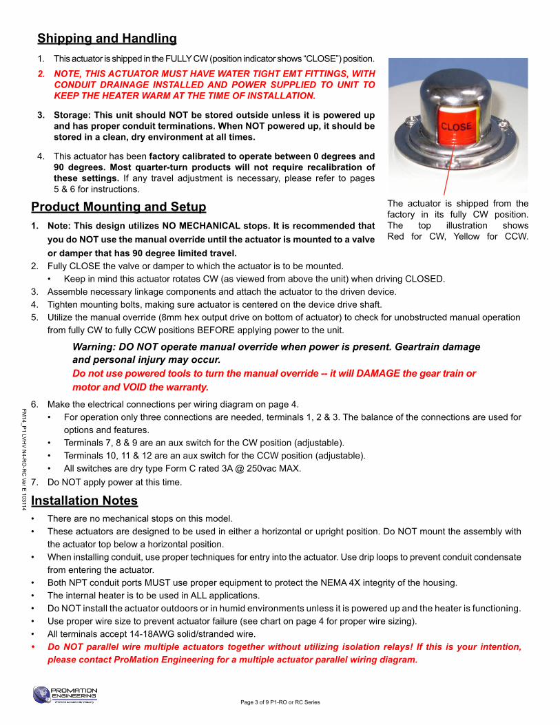
The actuator is shipped from the factory in its fully CW position. The top illustration shows Red for CW, Yellow for CCW.
Shipping and Handling1. This actuator is shipped in the FULLY CW (position indicator shows “CLOSE”) position.2. NOTE, THIS ACTUATOR MUST HAVE WATER TIGHT EMT FITTINGS, WITH
CONDUIT DRAINAGE INSTALLED AND POWER SUPPLIED TO UNIT TO KEEP THE HEATER WARM AT THE TIME OF INSTALLATION.
3. Storage: This unit should NOT be stored outside unless it is powered up and has proper conduit terminations. When NOT powered up, it should be stored in a clean, dry environment at all times.
4. This actuator has been factory calibrated to operate between 0 degrees and 90 degrees. Most quarter-turn products will not require recalibration of these settings. If any travel adjustment is necessary, please refer to pages 5 & 6 for instructions.
FM14
_P1
LVH
V N
4-R
O-R
C V
er E
103
114
Page 4 of 9 P1-RO or RC Series
2 Position Control
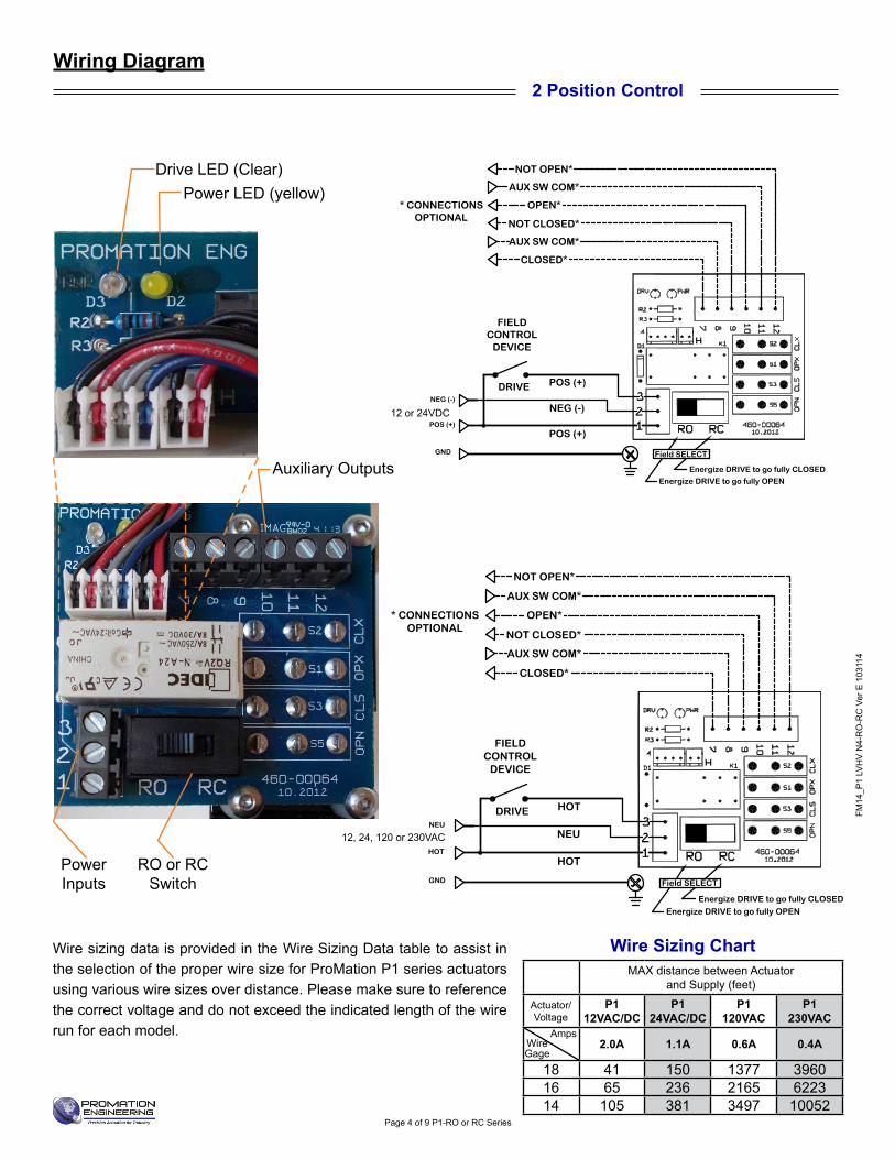
Wire sizing data is provided in the Wire Sizing Data table to assist in the selection of the proper wire size for ProMation P1 series actuators using various wire sizes over distance. Please make sure to reference the correct voltage and do not exceed the indicated length of the wire run for each model.
Wiring Diagram
Wire Sizing ChartMAX distance between Actuator
and Supply (feet)
Actuator/ Voltage
P112VAC/DC
P1 24VAC/DC
P1 120VAC
P1 230VAC
2.0A 1.1A 0.6A 0.4A
18 41 150 1377 396016 65 236 2165 622314 105 381 3497 10052
WireGage
Amps
RO or RC Switch
Power Inputs
Auxiliary Outputs
Power LED (yellow)Drive LED (Clear)
OPEN*
NOT CLOSED*
AUX SW COM*
CLOSED*
HOT
* CONNECTIONSOPTIONAL
FIELDCONTROL
DEVICE
GND
NEU
DRIVE
120VACNEU
HOT
HOT
NOT OPEN*
AUX SW COM*
Energize DRIVE to go fully OPEN
Energize DRIVE to go fully CLOSED
Field SELECT
OPEN*
NOT CLOSED*
AUX SW COM*
CLOSED*
HOT
* CONNECTIONSOPTIONAL
FIELDCONTROL
DEVICE
GND
NEU
DRIVE
120VACNEU
HOT
HOT
NOT OPEN*
AUX SW COM*
Energize DRIVE to go fully OPEN
Energize DRIVE to go fully CLOSED
Field SELECT
OPEN*
NOT CLOSED*
AUX SW COM*
CLOSED*
HOT
* CONNECTIONSOPTIONAL
FIELDCONTROL
DEVICE
GND
NEU
DRIVE
120VACNEU
HOT
HOT
NOT OPEN*
AUX SW COM*
Energize DRIVE to go fully OPEN
Energize DRIVE to go fully CLOSED
Field SELECT
OPEN*
NOT CLOSED*
AUX SW COM*
CLOSED*
HOT
* CONNECTIONSOPTIONAL
FIELDCONTROL
DEVICE
GND
NEU
DRIVE
120VACNEU
HOT
HOT
NOT OPEN*
AUX SW COM*
Energize DRIVE to go fully OPEN
Energize DRIVE to go fully CLOSED
Field SELECT
OPEN*
NOT CLOSED*
AUX SW COM*
CLOSED*
HOT
* CONNECTIONSOPTIONAL
FIELDCONTROL
DEVICE
GND
NEU
DRIVE
120VACNEU
HOT
HOT
NOT OPEN*
AUX SW COM*
Energize DRIVE to go fully OPEN
Energize DRIVE to go fully CLOSED
Field SELECT
OPEN*
NOT CLOSED*
AUX SW COM*
CLOSED*
HOT
* CONNECTIONSOPTIONAL
FIELDCONTROL
DEVICE
GND
NEU
DRIVE
120VACNEU
HOT
HOT
NOT OPEN*
AUX SW COM*
Energize DRIVE to go fully OPEN
Energize DRIVE to go fully CLOSED
Field SELECT
OPEN*
NOT CLOSED*
AUX SW COM*
CLOSED*
HOT
* CONNECTIONSOPTIONAL
FIELDCONTROL
DEVICE
GND
NEU
DRIVE
120VACNEU
HOT
HOT
NOT OPEN*
AUX SW COM*
Energize DRIVE to go fully OPEN
Energize DRIVE to go fully CLOSED
Field SELECT
OPEN*
NOT CLOSED*
AUX SW COM*
CLOSED*
HOT
* CONNECTIONSOPTIONAL
FIELDCONTROL
DEVICE
GND
NEU
DRIVE
120VACNEU
HOT
HOT
NOT OPEN*
AUX SW COM*
Energize DRIVE to go fully OPEN
Energize DRIVE to go fully CLOSED
Field SELECT
OPEN*
NOT CLOSED*
AUX SW COM*
CLOSED*
HOT
* CONNECTIONSOPTIONAL
FIELDCONTROL
DEVICE
GND
NEU
DRIVE
120VACNEU
HOT
HOT
NOT OPEN*
AUX SW COM*
Energize DRIVE to go fully OPEN
Energize DRIVE to go fully CLOSED
Field SELECT
OPEN*
NOT CLOSED*
AUX SW COM*
CLOSED*
POS (+)
* CONNECTIONSOPTIONAL
FIELDCONTROL
DEVICE
GND
NEG (-)
DRIVE
24VDCNEG (-)
POS (+)POS (+)
NOT OPEN*
AUX SW COM*
Energize DRIVE to go fully OPEN
Energize DRIVE to go fully CLOSED
Field SELECT
OPEN*
NOT CLOSED*
AUX SW COM*
CLOSED*
POS (+)
* CONNECTIONSOPTIONAL
FIELDCONTROL
DEVICE
GND
NEG (-)
DRIVE
24VDCNEG (-)
POS (+)POS (+)
NOT OPEN*
AUX SW COM*
Energize DRIVE to go fully OPEN
Energize DRIVE to go fully CLOSED
Field SELECT
OPEN*
NOT CLOSED*
AUX SW COM*
CLOSED*
POS (+)
* CONNECTIONSOPTIONAL
FIELDCONTROL
DEVICE
GND
NEG (-)
DRIVE
24VDCNEG (-)
POS (+)POS (+)
NOT OPEN*
AUX SW COM*
Energize DRIVE to go fully OPEN
Energize DRIVE to go fully CLOSED
Field SELECT
OPEN*
NOT CLOSED*
AUX SW COM*
CLOSED*
POS (+)
* CONNECTIONSOPTIONAL
FIELDCONTROL
DEVICE
GND
NEG (-)
DRIVE
24VDCNEG (-)
POS (+)
POS (+)
NOT OPEN*
AUX SW COM*
Energize DRIVE to go fully OPEN
Energize DRIVE to go fully CLOSED
Field SELECT
OPEN*
NOT CLOSED*
AUX SW COM*
CLOSED*
POS (+)
* CONNECTIONSOPTIONAL
FIELDCONTROL
DEVICE
GND
NEG (-)
DRIVE
24VDCNEG (-)
POS (+)
POS (+)
NOT OPEN*
AUX SW COM*
Energize DRIVE to go fully OPEN
Energize DRIVE to go fully CLOSED
Field SELECT
OPEN*
NOT CLOSED*
AUX SW COM*
CLOSED*
POS (+)
* CONNECTIONSOPTIONAL
FIELDCONTROL
DEVICE
GND
NEG (-)
DRIVE
24VDCNEG (-)
POS (+)
POS (+)
NOT OPEN*
AUX SW COM*
Energize DRIVE to go fully OPEN
Energize DRIVE to go fully CLOSED
Field SELECT
OPEN*
NOT CLOSED*
AUX SW COM*
CLOSED*
POS (+)
* CONNECTIONSOPTIONAL
FIELDCONTROL
DEVICE
GND
NEG (-)
DRIVE
24VDCNEG (-)
POS (+)
POS (+)
NOT OPEN*
AUX SW COM*
Energize DRIVE to go fully OPEN
Energize DRIVE to go fully CLOSED
Field SELECT
OPEN*
NOT CLOSED*
AUX SW COM*
CLOSED*
POS (+)
* CONNECTIONSOPTIONAL
FIELDCONTROL
DEVICE
GND
NEG (-)
DRIVE
24VDCNEG (-)
POS (+)
POS (+)
NOT OPEN*
AUX SW COM*
Energize DRIVE to go fully OPEN
Energize DRIVE to go fully CLOSED
Field SELECT
OPEN*
NOT CLOSED*
AUX SW COM*
CLOSED*
POS (+)
* CONNECTIONSOPTIONAL
FIELDCONTROL
DEVICE
GND
NEG (-)
DRIVE
24VDCNEG (-)
POS (+)
POS (+)
NOT OPEN*
AUX SW COM*
Energize DRIVE to go fully OPEN
Energize DRIVE to go fully CLOSED
Field SELECT
12 or 24VDC
12, 24, 120 or 230VAC
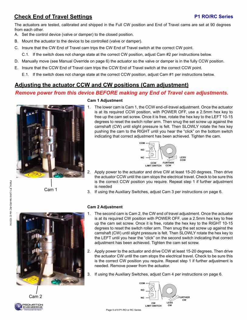
Remove power from this device BEFORE making any End of Travel cam adjustments.Cam 1 Adjustment1. The lower cam is Cam 1, the CCW end-of-travel adjustment. Once the actuator
is at its required CCW position, with POWER OFF, use a 2.5mm hex key to free up the cam set screw. Once it is free, rotate the hex key to the LEFT 10-15 degrees to reset the switch roller arm. Then snug the set screw up against the camshaft (CW) until slight pressure is felt. Then SLOWLY rotate the hex key pushing the cam to the RIGHT until you hear the “click” on the bottom switch indicating that correct adjustment has been achieved. Tighten the cam.
2. Apply power to the actuator and drive CW at least 15-20 degrees. Then drive the actuator CCW until the cam stops the electrical travel. Check to be sure this is the correct CCW position you require. Repeat step 1 if further adjustment is needed
3. If using the Auxiliary Switches, adjust Cam 3 per instructions on page 6.
Cam 2 Adjustment1. The second cam is Cam 2, the CW end of travel adjustment. Once the actuator
is at its required CW position with POWER OFF, use a 2.5mm hex key to free up the cam set screw. Once it is free, rotate the hex key to the RIGHT 10-15 degrees to reset the switch roller arm. Then snug the set screw up against the camshaft (CW) until slight pressure is felt. Then SLOWLY rotate the hex key to the LEFT until you hear the “click” on the second switch indicating that correct adjustment has been achieved. Tighten the cam set screw.
2. Apply power to the actuator and drive CCW at least 15-20 degrees. Then drive the actuator CW until the cam stops the electrical travel. Check to be sure this is the correct CW position you require. Repeat step 1 if further adjustment is needed. Remove power from the actuator.
3. If using the Auxiliary Switches, adjust Cam 4 per instructions on page 6.
Cam 1
Cam 2
NC
NO
COM
LESSCW
CWLIMIT SWITCH
FURTHERCW
FURTHERCCW
CCWLIMIT SWITCH
LESSCCW
NC
NO
COM
NC
NO
COM
LESSCLOSED
CLOSEDLIMIT SWITCH
FURTHERCLOSED
FURTHEROPEN
OPENLIMIT SWITCH
LESS OPEN
NC
NO
COM
NC
NO
COM
LESSCW
CWLIMIT SWITCH
FURTHERCW
FURTHERCCW
CCWLIMIT SWITCH
LESSCCW
NC
NO
COM
NC
NO
COM
LESSCLOSED
CLOSEDLIMIT SWITCH
FURTHERCLOSED
FURTHEROPEN
OPENLIMIT SWITCH
LESS OPEN
NC
NO
COM
The actuators are tested, calibrated and shipped in the Full CW position and End of Travel cams are set at 90 degrees from each other.A. Set the control device (valve or damper) to the closed position.B. Mount the actuator to the device to be controlled (valve or damper).C. Insure that the CW End of Travel cam trips the CW End of Travel switch at the correct CW point.
C.1. If the switch does not change state at the correct CW position, adjust Cam #2 per instructions below.D. Manually move (see Manual Override on page 6) the actuator so the valve or damper is in the fully CCW position.E. Insure that the CCW End of Travel cam trips the CCW End of Travel switch at the correct CCW point.
E.1. If the switch does not change state at the correct CCW position, adjust Cam #1 per instructions below.
P1 RO/RC Series
FM14_P
1 LVH
V N
4-RO
-RC
Ver E 103114
Page 5 of 9 P1-RO or RC Series
Adjusting the actuator CCW and CW positions (Cam adjustment)
Check End of Travel Settings
P1 RO/RC SeriesRemove power from this device BEFORE making any End of Travel cam adjustments.
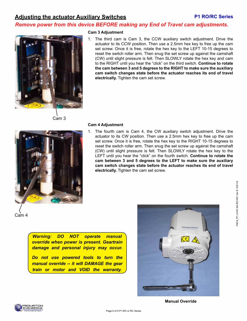
Cam 3 Adjustment1. The third cam is Cam 3, the CCW auxiliary switch adjustment. Drive the
actuator to its CCW position. Then use a 2.5mm hex key to free up the cam set screw. Once it is free, rotate the hex key to the LEFT 10-15 degrees to reset the switch roller arm. Then snug the set screw up against the camshaft (CW) until slight pressure is felt. Then SLOWLY rotate the hex key and cam to the RIGHT until you hear the “click” on the third switch. Continue to rotate the cam between 3 and 5 degrees to the RIGHT to make sure the auxiliary cam switch changes state before the actuator reaches its end of travel electrically. Tighten the cam set screw.
Cam 4 Adjustment1. The fourth cam is Cam 4, the CW auxiliary switch adjustment. Drive the
actuator to its CW position. Then use a 2.5mm hex key to free up the cam set screw. Once it is free, rotate the hex key to the RIGHT 10-15 degrees to reset the switch roller arm. Then snug the set screw up against the camshaft (CW) until slight pressure is felt. Then SLOWLY rotate the hex key to the LEFT until you hear the “click” on the fourth switch. Continue to rotate the cam between 3 and 5 degrees to the LEFT to make sure the auxiliary cam switch changes state before the actuator reaches its end of travel electrically. Tighten the cam set screw.
Cam 3
Cam 4
Warning: DO NOT operate manual override when power is present. Geartrain damage and personal injury may occur.
Do not use powered tools to turn the manual override -- it will DAMAGE the gear train or motor and VOID the warranty.
Manual Override
FM14
_P1
LVH
V N
4-R
O-R
C V
er E
103
114
Page 6 of 9 P1-RO or RC Series
Adjusting the actuator Auxiliary Switches
FM14_P
1 LVH
V N
4-RO
-RC
Ver E 103114
Page 7 of 9 P1-RO or RC Series
Drawn By
Finish
Promation Engineering Inc.16138 Flight Path Drive
Brooksville, Fl 34604Phone: 352-544-8436Fax: 352-544-8439
This Document is the property of ProMation Engineering,Inc. Distribution of this document without the written
consent of the owner is Strictly forbidden. Failure to comply will incur a liability for Damages.
Checked By4/15/2014
P1 Proportional Dimensional Data Rev.
E
NO SCALE Sheet Number: 1
Material
ProMation Engineering, Inc.KHL
KHL
4/24/2013
P1 F05 8P14 DimData.idw
Created:
Last Checked:
Part No.
Dwg. Name
Dimensional Data for P1 On/Off Actuators
Engineering Change NoticeChange Date Description Name
04.25.13 Transferred document into Inventor file KHL
04.15.13 Added tolerance on drive coupling data KHL
10.07.2014 Pushed square dimension to three decimal places KHL
REVA
B
C
D
E
F
Dimensional Tolerances (Unless Otherwise Noted):X ± 2.5mm [X.X ± .1]
X.X ± .3mm [X.XX ± .01"]X.XX ± .13mm [X.XXX ± .005"]
ALL TOLERANCE FEATURES IN mm
1
1
2
2
A A
B B
14.00 - .13.00+ mm
0.551 - 0.0050.000+ in
14.00 - .13.00+ mm
0.551 - 0.0050.000+ in
15.00 mm0.591 in
Drive Coupling Fabrication Data
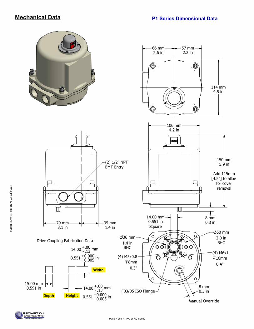
66 mm2.6 in
57 mm2.2 in
114 mm4.5 in
106 mm4.2 in
150 mm5.9 in
Add 115mm
[4.5"] to allowfor coverremoval
8 mm0.3 in79 mm
3.1 in35 mm1.4 in
(2) 1/2" NPTEMT Entry
14.00 mm0.551 inSquare
50 mm2.0 inBHC
36 mm1.4 inBHC
M6x1(4) 10mm 0.4"
8 mm0.3 inF03/05 ISO Flange
M5x0.8(4) 8mm
0.3"
Depth Height
Width
Mechanical Data P1 Series Dimensional Data
Manual Override
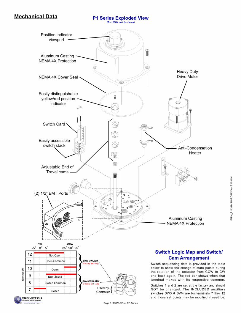
P1 Series Exploded View (P1-120N4 unit is shown)
Position indicator viewport
Easily distinguishable yellow/red position
indicator
Heavy Duty Drive Motor
Easily accessible switch stack
Adjustable End of Travel cams
(2) 1/2” EMT Ports
Switch Card
Anti-Condensation Heater
Aluminum CastingNEMA 4X Protection
Aluminum CastingNEMA 4X Protection
NEMA 4X Cover Seal
Switch Logic Map and Switch/Cam Arrangement
Switch sequencing data is provided in the table below to show the change-of-state points during the rotation of the actuator from CCW to CW and back again. The red bar shows when that terminal makes with its respective common.
Switches 1 and 2 are set at the factory and should NOT be changed. The INCLUDED auxi l iary switches SW3 & SW4 are for terminals 7 thru 12 and those set pointsmay bemodified if need be.
FM14
_P1
LVH
V N
4-R
O-R
C V
er E
103
114
Page 8 of 9 P1-RO or RC Series
Mechanical DataTe
rmin
al ID
#
12
11
10
9
8
7
-5° 0°CW CCW
85°5° 90° 95°
SW4 CCW AUX(Factory Set - Adj)
SW3 CW AUX(Factory Set - Adj)}
}Closed Common
Open Common
}Used by Controller
Open
Not Closed
Closed
Not Open
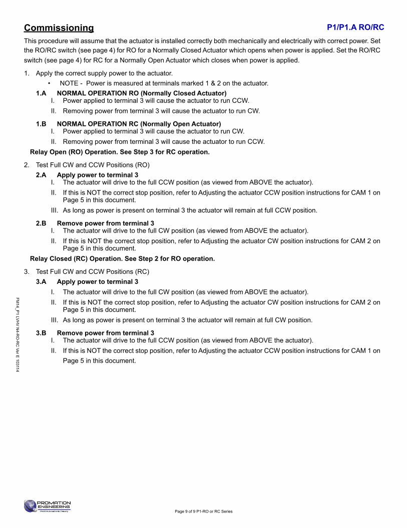
P1/P1.A RO/RC This procedure will assume that the actuator is installed correctly both mechanically and electrically with correct power. Set the RO/RC switch (see page 4) for RO for a Normally Closed Actuator which opens when power is applied. Set the RO/RC switch (see page 4) for RC for a Normally Open Actuator which closes when power is applied.
1. Apply the correct supply power to the actuator.• NOTE - Power is measured at terminals marked 1 & 2 on the actuator.
1.A NORMAL OPERATION RO (Normally Closed Actuator)I. Power applied to terminal 3 will cause the actuator to run CCW.II. Removing power from terminal 3 will cause the actuator to run CW.
1.B NORMAL OPERATION RC (Normally Open Actuator)I. Power applied to terminal 3 will cause the actuator to run CW.II. Removing power from terminal 3 will cause the actuator to run CCW.
Relay Open (RO) Operation. See Step 3 for RC operation.
2. Test Full CW and CCW Positions (RO)2.A Apply power to terminal 3
I. The actuator will drive to the full CCW position (as viewed from ABOVE the actuator). II. If this is NOT the correct stop position, refer to Adjusting the actuator CCW position instructions for CAM 1 on
Page 5 in this document.III. As long as power is present on terminal 3 the actuator will remain at full CCW position.
2.B Remove power from terminal 3I. The actuator will drive to the full CW position (as viewed from ABOVE the actuator). II. If this is NOT the correct stop position, refer to Adjusting the actuator CW position instructions for CAM 2 on
Page 5 in this document.Relay Closed (RC) Operation. See Step 2 for RO operation.
3. Test Full CW and CCW Positions (RC)3.A Apply power to terminal 3
I. The actuator will drive to the full CW position (as viewed from ABOVE the actuator). II. If this is NOT the correct stop position, refer to Adjusting the actuator CW position instructions for CAM 2 on
Page 5 in this document.III. As long as power is present on terminal 3 the actuator will remain at full CW position.
3.B Remove power from terminal 3I. The actuator will drive to the full CCW position (as viewed from ABOVE the actuator). II. If this is NOT the correct stop position, refer to Adjusting the actuator CCW position instructions for CAM 1 on
Page 5 in this document.
FM14_P
1 LVH
V N
4-RO
-RC
Ver E 103114
Page 9 of 9 P1-RO or RC Series
Commissioning

Industrial ApplicationsProMationEngineeringactuatorshavebeeninstalledtooperateprocesscontrolssuchasbutterflyvalves, ball valves, high performance valves, plug valves, gate valves and dampers, in a broad range of demanding industrial applications.
Power Generation
Water Processes Mining Oil and Gas Agriculture Chemicals
16138 Flight Path Drive Brooksville, FL 34604
Phone (352) 544-8436 Fax (352) 544-8439email: sales@promationei .com
Complete Support
Full Documentation Weoffercompletewiringdiagrams,fieldinstallationmanualsandsetupdocumentation for all our products, both in printed and digital form. We regularly host customized educational webinars for our customers.
RapidQuoteMost quotes and estimates are generated within hours of the request.
ProMation Engineering Services ProMation Engineering can provide design and technical services for OEM’s, projects with customized requirements and specialized operations.
ProMation Engineering is committed to providing superior customer support for your sales, project management and installation teams. Contact us today.
ProMation Engineering follows a policy of continual product updates and enhancements. Our website is the best place to obtain the latest product documentation, including the wiring diagrams for these
controllers. Visit us at www.promationei.com or use the code to link to the site.
Use your smart phone barcode scanner app here.