INSTALLATION & OPERATION MANUAL - Hyundai SeasAll · INSTALLATION & OPERATION MANUAL L500 Series -...
71
INSTALLATION & OPERATION MANUAL L500 Series
Transcript of INSTALLATION & OPERATION MANUAL - Hyundai SeasAll · INSTALLATION & OPERATION MANUAL L500 Series -...

INSTALLATION & OPERATION MANUAL
L500 Series
INSTALLATION & OPERATION MANUAL
L500 Series
- 1 -
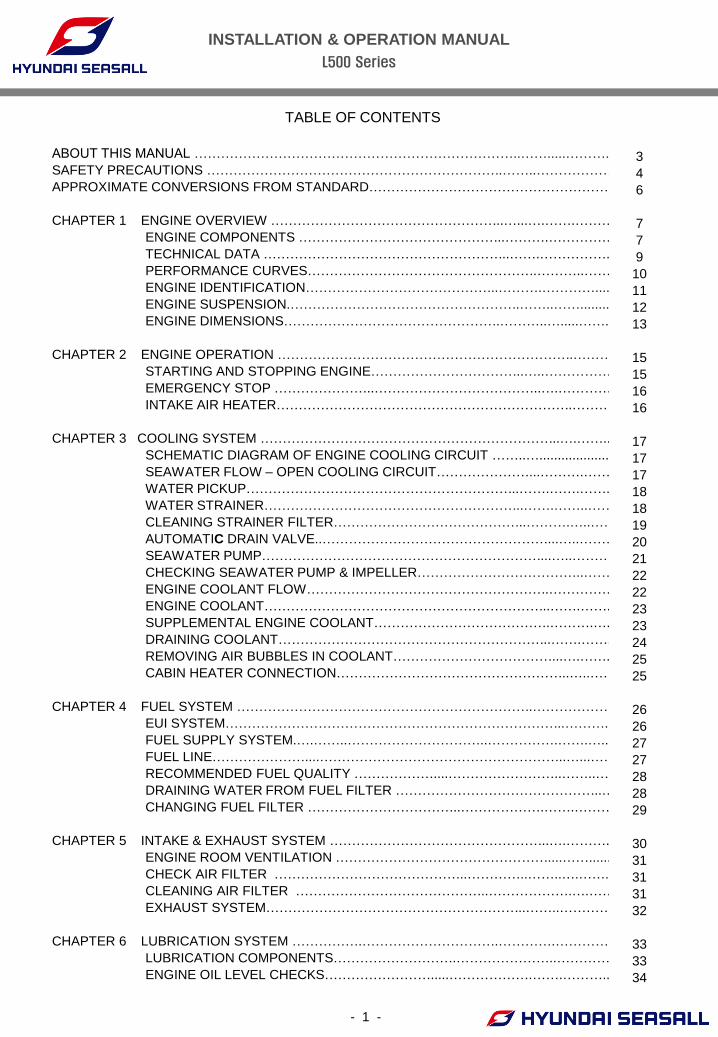
TABLE OF CONTENTS
ABOUT THIS MANUAL ………………………………………………………………..…….....………..
SAFETY PRECAUTIONS ………………………………………………………….……..………………
APPROXIMATE CONVERSIONS FROM STANDARD………………………………………………
CHAPTER 1 ENGINE OVERVIEW ……………………………………………..…...….…….………
ENGINE COMPONENTS ………………………………………..……….……………
TECHNICAL DATA ………………………………………………..…….……………..
PERFORMANCE CURVES…………………………………………….………..……..
ENGINE IDENTIFICATION……………………………………..……….………….....
ENGINE SUSPENSION.…………………………………………….……..……...........
ENGINE DIMENSIONS………………………………………….………..….....……..
CHAPTER 2 ENGINE OPERATION ………………………………………………………….………..
STARTING AND STOPPING ENGINE……………………………..…..…………….
EMERGENCY STOP …………………..………………………………..….…………..
INTAKE AIR HEATER………………………………………………………….………..
CHAPTER 3 COOLING SYSTEM …………………………………………………………..….……...
SCHEMATIC DIAGRAM OF ENGINE COOLING CIRCUIT ……..…....................
SEAWATER FLOW – OPEN COOLING CIRCUIT…………………...……….…….
WATER PICKUP……………………………………………………..…….…….……..
WATER STRAINER…………………………………………………..…….……..…….
CLEANING STRAINER FILTER……………………………………..……….…..………
AUTOMATIC DRAIN VALVE..……………………………………………...…..………
SEAWATER PUMP………………………………………………………...…..………
CHECKING SEAWATER PUMP & IMPELLER………………………………..……..
ENGINE COOLANT FLOW……………………………………………….…………….
ENGINE COOLANT………………………………………………………..…….…….
SUPPLEMENTAL ENGINE COOLANT………………………………….……….….
DRAINING COOLANT……………………………………………………..…….…….
REMOVING AIR BUBBLES IN COOLANT………………………………...….……..
CABIN HEATER CONNECTION……………………………………………..…..……
CHAPTER 4 FUEL SYSTEM ………………………………………………………….………………..
EUI SYSTEM…………………………………………………………………..………..
FUEL SUPPLY SYSTEM.….……..…………………………..…………….…….…...
FUEL LINE…………………....………………………………………………..…...……
RECOMMENDED FUEL QUALITY ………………....……………………..……..….
DRAINING WATER FROM FUEL FILTER ………………………………………..….
CHANGING FUEL FILTER ……………………………..……………….…….………..
CHAPTER 5 INTAKE & EXHAUST SYSTEM …………………………………………..….………..
ENGINE ROOM VENTILATION …………………………………………....……......
CHECK AIR FILTER ……………………………………..…………..……..….……..
CLEANING AIR FILTER ……………………………………..……………….….……
EXHAUST SYSTEM…………………………………………………..……..…………
CHAPTER 6 LUBRICATION SYSTEM …………….………………………….………….…………
LUBRICATION COMPONENTS……………………….…………………..…………
ENGINE OIL LEVEL CHECKS…………………….....……………….…….………..
3
4
6
7
7
9
10
11
12
13
15
15
16
16
17
17
17
18
18
19
20
21
22
22
23
23
24
25
25
26
26
27
27
28
28
29
30
31
31
31
32
33
33
34
INSTALLATION & OPERATION MANUAL
L500 Series
- 2 -
TABLE OF CONTENTS
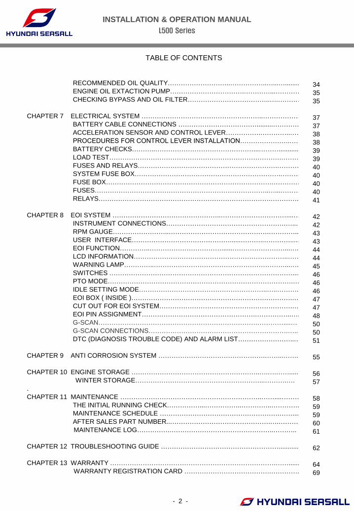
RECOMMENDED OIL QUALITY………………………..……………..…...…........
ENGINE OIL EXTACTION PUMP…………………………….…………...………….
CHECKING BYPASS AND OIL FILTER………………………………..….…………
CHAPTER 7 ELECTRICAL SYSTEM ………………………………………………..………………
BATTERY CABLE CONNECTIONS ……………………………….........…………..
ACCELERATION SENSOR AND CONTROL LEVER…………….…………..……
PROCEDURES FOR CONTROL LEVER INSTALLATION…………………..……
BATTERY CHECKS………..………………………………………...………...........
LOAD TEST…………………………………………………………………….………
FUSES AND RELAYS……………………………………………………….…………
SYSTEM FUSE BOX………………………………………………………….………..
FUSE BOX………………………………………………………………….……………
FUSES……………………………………………………………………..…...………
RELAYS…………………………………………………………………….………….
CHAPTER 8 EOI SYSTEM …………………………………………..…………………………....…
INSTRUMENT CONNECTIONS……………………………………………….…..…
RPM GAUGE……………………..……………………………………….…………...
USER INTERFACE………………………………………......………..…………...…
EOI FUNCTION…………..……………………………......……………………...….
LCD INFORMATION……………………………………………………………..……
WARNING LAMP…………..……………………………………………………...….
SWITCHES …………………………………………………………………………......
PTO MODE………………………………………………………………………….…
IDLE SETTING MODE…………………………………………………..…..……….
EOI BOX ( INSIDE )…………………………………………………….………….…
CUT OUT FOR EOI SYSTEM…………………………………………………….….
EOI PIN ASSIGNMENT…………………………………………….……………..….
G-SCAN……………………………………………………………….…………....…
G-SCAN CONNECTIONS……………………………………………………….…..
DTC (DIAGNOSIS TROUBLE CODE) AND ALARM LIST……………………..…
CHAPTER 9 ANTI CORROSION SYSTEM ………………………………………….……...……..
CHAPTER 10 ENGINE STORAGE …………………………………………………..….….…….....
WINTER STORAGE…………………………………………………...……….….
.
CHAPTER 11 MAINTENANCE ………………………………………………………..……....……….
THE INITIAL RUNNING CHECK……………...……………..…………..………….
MAINTENANCE SCHEDULE ……………………………………………….…….....
AFTER SALES PART NUMBER..……………………………………….….………..
MAINTENANCE LOG…………….………………………………………..………..
CHAPTER 12 TROUBLESHOOTING GUIDE ………………………………………………............
CHAPTER 13 WARRANTY ………………………………………………………………….……......
WARRANTY REGISTRATION CARD ………………………………….…………..
34
35
35
37
37
38
38
39
39
40
40
40
40
41
42
42
43
43
44
44
45
46
46
46
47
47
48
50
50
51
55
56
57
58
59
59
60
61
62
64
69
INSTALLATION & OPERATION MANUAL
L500 Series
- 3 -
ABOUT THIS MANUAL
This engine installation and operation manual is provided as guidance for the installation of
Hyundai SeasAll engine in a boat, and to describe engine operation. Its purpose is to provide
technical information to aid in performing an effective engine installation so as to achieve both
maximum performance and service life.
Hyundai SeasAll is committed to making clear and accurate information available for those who
maintain, own and repair the L500 Series engines. Hyundai SeasAll values your input regarding
revisions and additional information for our manuals.
WARNING DEVIATION FROM INSTALLATION INSTRUCTIONS AND OPERATION
GUIDELINES MAY LEAD TO PERSONAL INJURY OR DEATH TO
OPERATORS AND NEARBY PERSONNEL.
CAUTION DEVIATION FROM INSTALLATION INSTRUCTIONS AND OPERATION
GUIDELINES MAY LEAD TO IMPROPER OPERATION, DAMAGE OR
DESTRUCTION OF THE ENGINE.
• The manufacturer is not liable for any damages or losses caused by faulty installation, wrong
handling of the equipment and/or deficient maintenance.
• The operator is responsible for the correct and safe operation of the engine and safety of its
occupants and general public.
• It is strongly recommended that each operator read and understand this manual before
installing and operating the engine.
• This manual as well as safety labels posted on the engine use the following safety alerts to
draw your attention to special safety instructions that should be followed.
• Illustrations in this manual are subject to change without notice.
INSTALLATION & OPERATION MANUAL
L500 Series
- 4 -
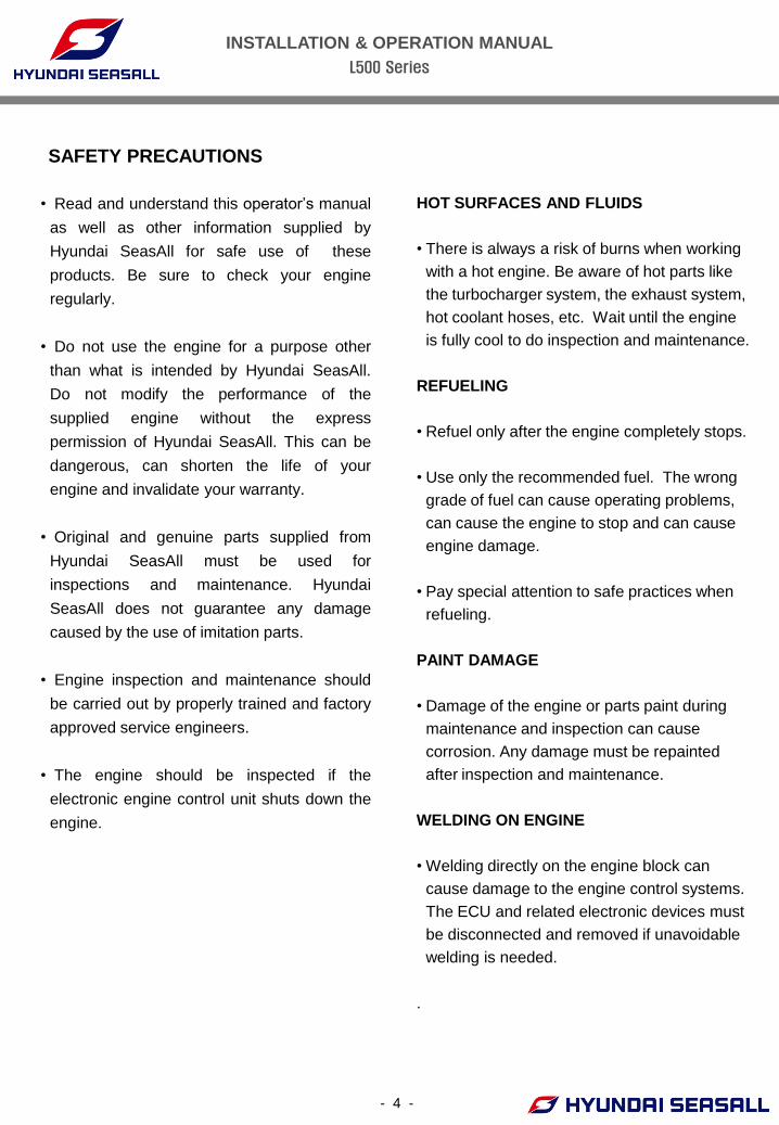
SAFETY PRECAUTIONS
HOT SURFACES AND FLUIDS
• There is always a risk of burns when working
with a hot engine. Be aware of hot parts like
the turbocharger system, the exhaust system,
hot coolant hoses, etc. Wait until the engine
is fully cool to do inspection and maintenance.
REFUELING
• Refuel only after the engine completely stops.
• Use only the recommended fuel. The wrong
grade of fuel can cause operating problems,
can cause the engine to stop and can cause
engine damage.
• Pay special attention to safe practices when
refueling.
PAINT DAMAGE
• Damage of the engine or parts paint during
maintenance and inspection can cause
corrosion. Any damage must be repainted
after inspection and maintenance.
WELDING ON ENGINE
• Welding directly on the engine block can
cause damage to the engine control systems.
The ECU and related electronic devices must
be disconnected and removed if unavoidable
welding is needed.
.
• Read and understand this operator’s manual
as well as other information supplied by
Hyundai SeasAll for safe use of these
products. Be sure to check your engine
regularly.
• Do not use the engine for a purpose other
than what is intended by Hyundai SeasAll.
Do not modify the performance of the
supplied engine without the express
permission of Hyundai SeasAll. This can be
dangerous, can shorten the life of your
engine and invalidate your warranty.
• Original and genuine parts supplied from
Hyundai SeasAll must be used for
inspections and maintenance. Hyundai
SeasAll does not guarantee any damage
caused by the use of imitation parts.
• Engine inspection and maintenance should
be carried out by properly trained and factory
approved service engineers.
• The engine should be inspected if the
electronic engine control unit shuts down the
engine.
INSTALLATION & OPERATION MANUAL
L500 Series
- 5 -
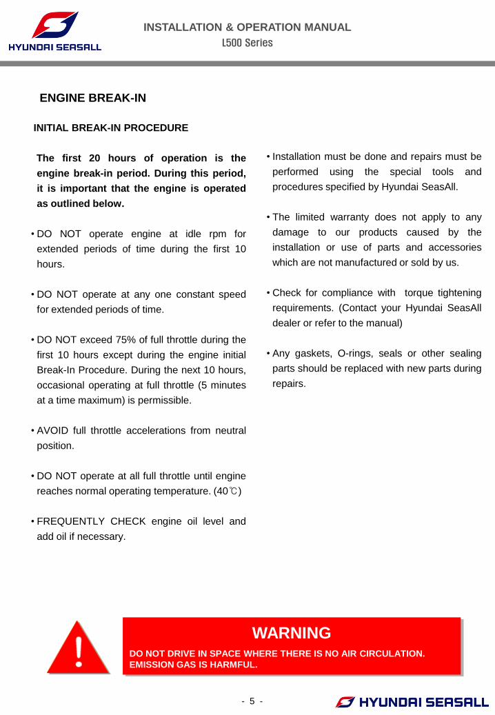
ENGINE BREAK-IN
WARNING DO NOT DRIVE IN SPACE WHERE THERE IS NO AIR CIRCULATION.
EMISSION GAS IS HARMFUL.
INITIAL BREAK-IN PROCEDURE
The first 20 hours of operation is the
engine break-in period. During this period,
it is important that the engine is operated
as outlined below.
• DO NOT operate engine at idle rpm for
extended periods of time during the first 10
hours.
• DO NOT operate at any one constant speed
for extended periods of time.
• DO NOT exceed 75% of full throttle during the
first 10 hours except during the engine initial
Break-In Procedure. During the next 10 hours,
occasional operating at full throttle (5 minutes
at a time maximum) is permissible.
• AVOID full throttle accelerations from neutral
position.
• DO NOT operate at all full throttle until engine
reaches normal operating temperature. (40℃)
• FREQUENTLY CHECK engine oil level and
add oil if necessary.
• Installation must be done and repairs must be
performed using the special tools and
procedures specified by Hyundai SeasAll.
• The limited warranty does not apply to any
damage to our products caused by the
installation or use of parts and accessories
which are not manufactured or sold by us.
• Check for compliance with torque tightening
requirements. (Contact your Hyundai SeasAll
dealer or refer to the manual)
• Any gaskets, O-rings, seals or other sealing
parts should be replaced with new parts during
repairs.
INSTALLATION & OPERATION MANUAL
L500 Series
- 6 -
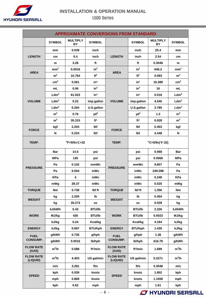
APPROXIMATE CONVERSIONS FROM STANDARD
SYMBOL MULTIPLY
BY SYMBOL SYMBOL
MULTIPLY
BY SYMBOL
LENGTH
mm 0.039 inch
LENGTH
inch 25.4 mm
cm 0.4 inch inch 2.54 cm
m 3.28 ft ft 0.3048 m
AREA mm2 0.0016 in2
AREA in2 645.2 mm2
m2 10.764 ft2 ft2 0.093 m2
VOLUME
cm3 0.061 in³
VOLUME
in³ 16.388 cm3
mL 0.06 in3 in3 16 mL
Ldm3 61.023 in³ in³ 0.016 Ldm3
Ldm3 0.22 imp.gallon imp.gallon 4.545 Ldm3
Ldm3 0.264 U.S.gallon U.S.gallon 3.785 Ldm3
m3 0.76 yd3 yd3 1.3 m3
m3 35.315 ft³ ft³ 0.028 m3
FORCE kgf 2.204 lbf
FORCE lbf 0.453 kgf
N 0.224 lbf lbf 4.448 N
TEMP. oF=9/5x℃+32 TEMP. oC=5/9x(℉-32)
PRESSURE
Bar 14.5 psi
PRESSURE
psi 0.068 Bar
MPa 145 psi psi 0.0068 MPa
Pa 0.102 mmWc mmWc 9.807 Pa
Pa 0.004 inWc inWc 249.098 Pa
KPa 4 inWc inWc 0.249 KPa
mWg 39.37 inWc inWc 0.025 mWg
TORQUE Nm 0.738 lbf ft TORQUE lbf ft 1.356 Nm
WEIGHT kg 2.205 lb
WEIGHT lb 0.454 kg
kg 35.273 oz oz 0.028 kg
WORK
kJ/kWh 0.43 BTU/lb
WORK
BTU/lb 2.326 kJ/kWh
MJ/kg 430 BTU/lb BTU/lb 0.0023 MJ/kg
kJ/kg 0.24 Kcal/kg Kcal/kg 4.184 kJ/kg
ENERGY kJ/kg 0.697 BTU/hph ENERGY BTU/hph 1.435 kJ/kg
FUEL
CONSUMP.
g/kWh 0.736 g/hph FUEL
CONSUMP.
g/hph 1.36 g/kWh
g/kWh 0.0016 lb/hph lb/hph 616.78 g/kWh
FLOW RATE
(GAS) m3/h 0.588 ft³/min
FLOW RATE
(GAS) ft³/min 1.699 m3/h
FLOW RATE
(LIQUID) m3/h 4.403 US gal/min
FLOW RATE
(LIQUID) US gal/min 0.2271 m3/h
SPEED
m/s 3.281 ft/s
SPEED
ft/s 0.3048 m/s
kph 0.539 knots knots 1.852 kph
mph 0.869 knots knots 1.1508 mph
kph 0.62 mph mph 1.61 kph
INSTALLATION & OPERATION MANUAL
L500 Series
- 7 -
CHAPTER 1
ENGINE OVERVIEW
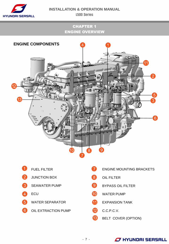
ENGINE COMPONENTS
① FUEL FILTER ENGINE MOUNTING BRACKETS
② JUNCTION BOX OIL FILTER
③ SEAWATER PUMP BYPASS OIL FILTER
④ ECU WATER PUMP
⑤ WATER SEPARATOR EXPANSION TANK
⑥ OIL EXTRACTION PUMP C.C.P.C.V.
BELT COVER (OPTION)

INSTALLATION & OPERATION MANUAL
L500 Series
INTERCOOLER COOLANT PIPE (HEAT EXCHANGER OUTLET)
DRY EXHAUST PIPE STARTER MOTOR
TURBO-CHARGER OUTLET PIPE ENGINE MOUNTING BRACKET
LIFTING EYES HEAT EXCHANGER
AIR FILTER EXHAUST MANIFOLD
AIR FILTER CONNECTOR
ALTERNATOR
- 8 -
INSTALLATION & OPERATION MANUAL
L500 Series
- 9 -
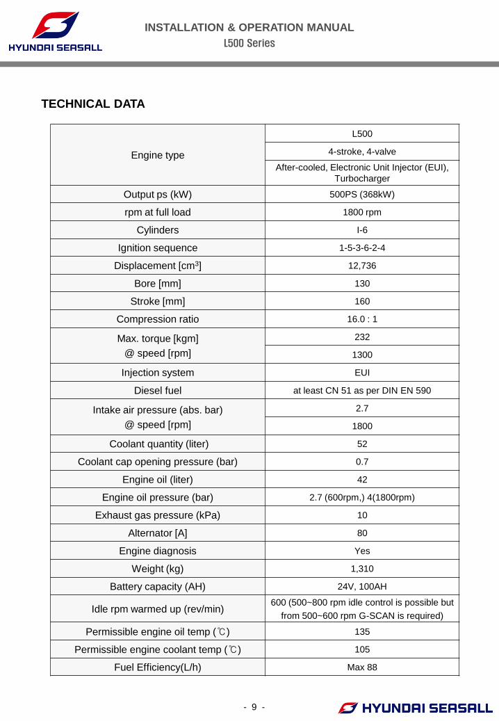
TECHNICAL DATA
Engine type
L500
4-stroke, 4-valve
After-cooled, Electronic Unit Injector (EUI),
Turbocharger
Output ps (kW) 500PS (368kW)
rpm at full load 1800 rpm
Cylinders I-6
Ignition sequence 1-5-3-6-2-4
Displacement [cm3] 12,736
Bore [mm] 130
Stroke [mm] 160
Compression ratio 16.0 : 1
Max. torque [kgm]
@ speed [rpm]
232
1300
Injection system EUI
Diesel fuel at least CN 51 as per DIN EN 590
Intake air pressure (abs. bar)
@ speed [rpm]
2.7
1800
Coolant quantity (liter) 52
Coolant cap opening pressure (bar) 0.7
Engine oil (liter) 42
Engine oil pressure (bar) 2.7 (600rpm,) 4(1800rpm)
Exhaust gas pressure (kPa) 10
Alternator [A] 80
Engine diagnosis Yes
Weight (kg) 1,310
Battery capacity (AH) 24V, 100AH
Idle rpm warmed up (rev/min) 600 (500~800 rpm idle control is possible but
from 500~600 rpm G-SCAN is required)
Permissible engine oil temp (℃) 135
Permissible engine coolant temp (℃) 105
Fuel Efficiency(L/h) Max 88
INSTALLATION & OPERATION MANUAL
L500 Series
- 10 -
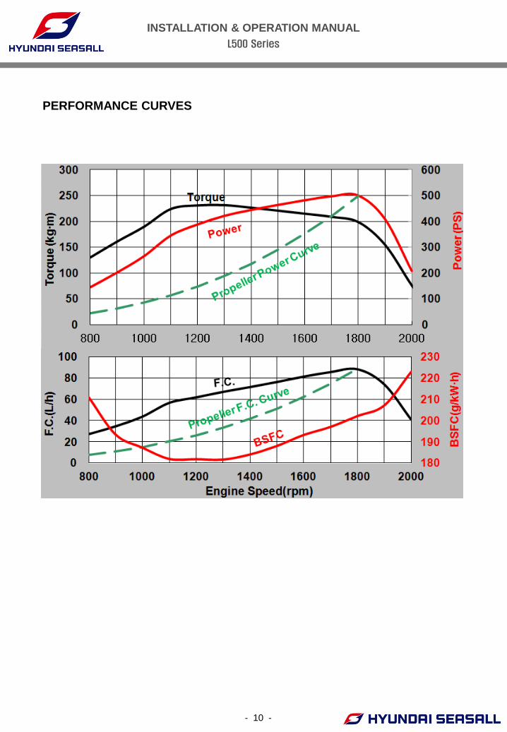
PERFORMANCE CURVES
INSTALLATION & OPERATION MANUAL
L500 Series
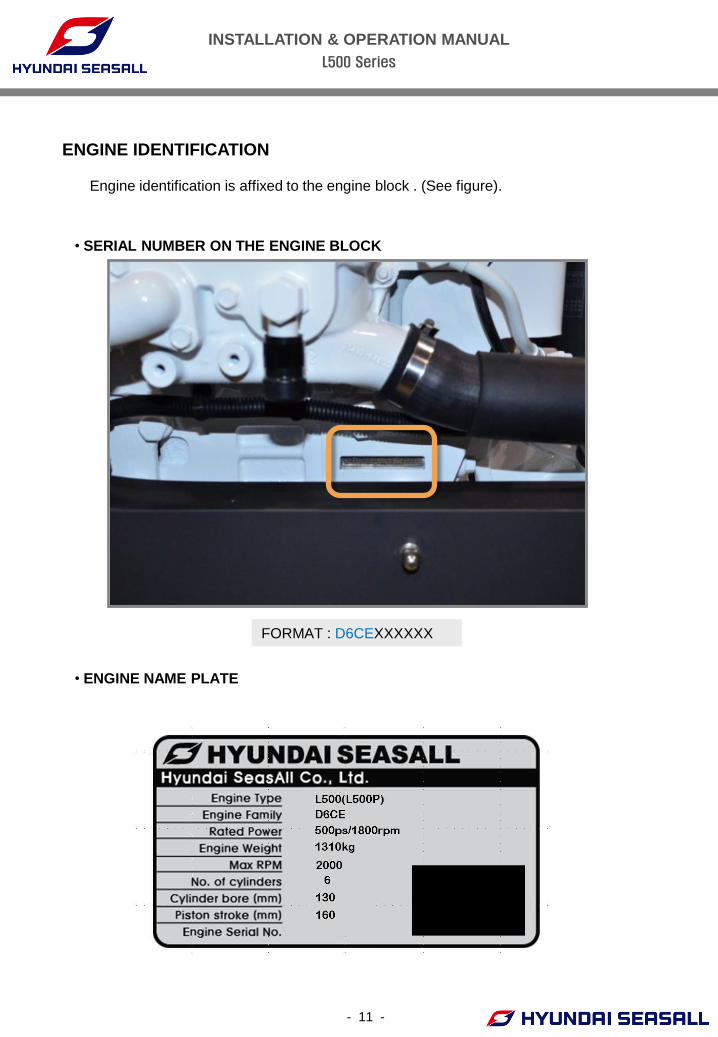
ENGINE IDENTIFICATION
• SERIAL NUMBER ON THE ENGINE BLOCK
Engine identification is affixed to the engine block . (See figure).
• ENGINE NAME PLATE
FORMAT : D6CEXXXXXX
- 11 -
INSTALLATION & OPERATION MANUAL
L500 Series
- 12 -
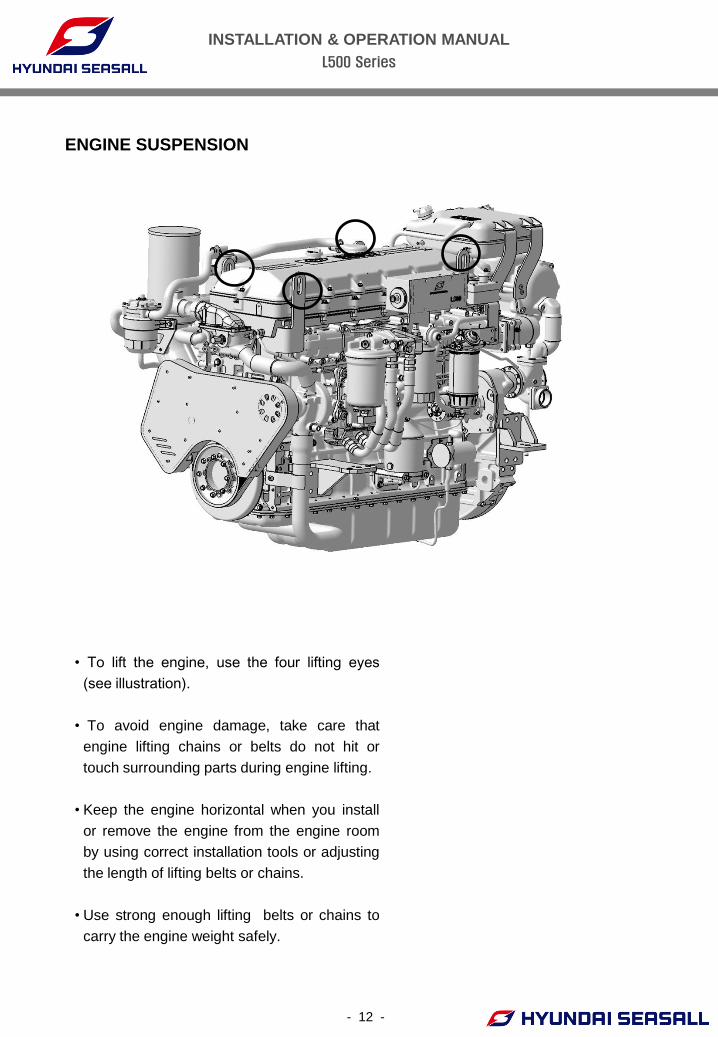
• To lift the engine, use the four lifting eyes
(see illustration).
• To avoid engine damage, take care that
engine lifting chains or belts do not hit or
touch surrounding parts during engine lifting.
• Keep the engine horizontal when you install
or remove the engine from the engine room
by using correct installation tools or adjusting
the length of lifting belts or chains.
• Use strong enough lifting belts or chains to
carry the engine weight safely.
ENGINE SUSPENSION
INSTALLATION & OPERATION MANUAL
L500 Series
- 13 -
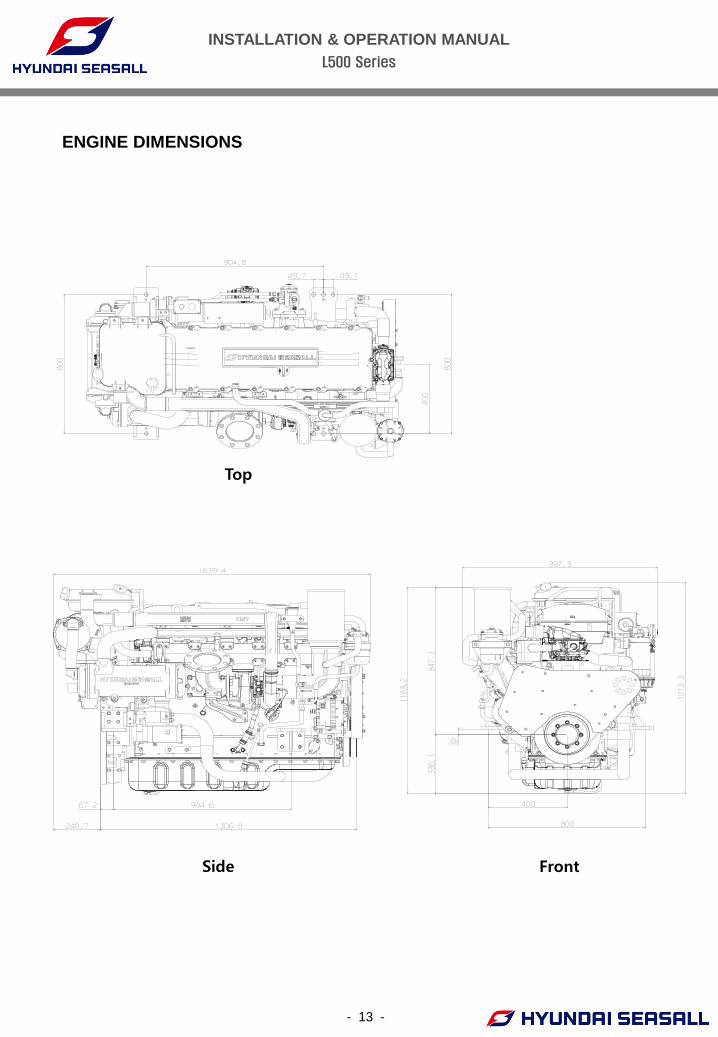
ENGINE DIMENSIONS
Top
Side Front
INSTALLATION & OPERATION MANUAL
L500 Series
- 14 -
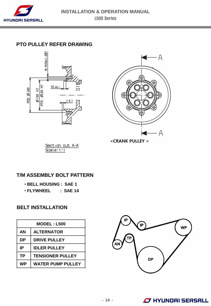
<CRANK PULLEY >
T/M ASSEMBLY BOLT PATTERN
• BELL HOUSING : SAE 1
• FLYWHEEL : SAE 14
BELT INSTALLATION
MODEL : L500
AN ALTERNATOR
DP DRIVE PULLEY
IP IDLER PULLEY
TP TENSIONER PULLEY
WP WATER PUMP PULLEY
PTO PULLEY REFER DRAWING
INSTALLATION & OPERATION MANUAL
L500 Series
- 15 -
CHAPTER 2
ENGINE OPERATION
STARTING ENGINE
WARNING DO NOT DRIVE IN SPACE WHERE THERE IS NO AIR CIRCULATION.
EMISSION GAS IS HARMFUL.
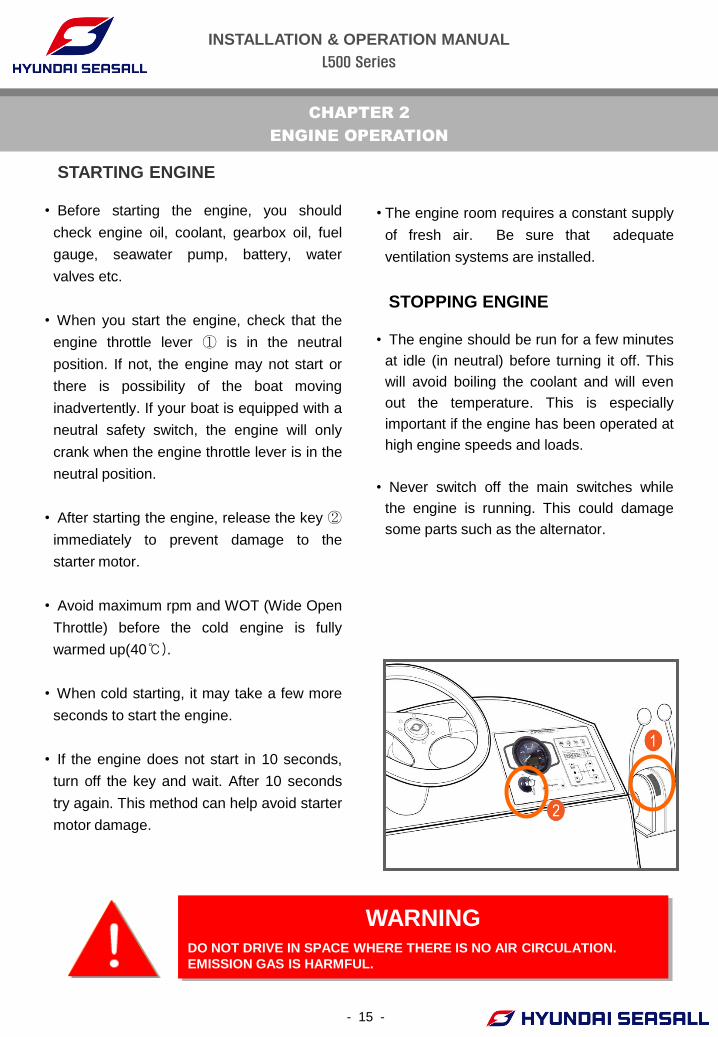
• Before starting the engine, you should
check engine oil, coolant, gearbox oil, fuel
gauge, seawater pump, battery, water
valves etc.
• When you start the engine, check that the
engine throttle lever ① is in the neutral
position. If not, the engine may not start or
there is possibility of the boat moving
inadvertently. If your boat is equipped with a
neutral safety switch, the engine will only
crank when the engine throttle lever is in the
neutral position.
• After starting the engine, release the key ②
immediately to prevent damage to the
starter motor.
• Avoid maximum rpm and WOT (Wide Open
Throttle) before the cold engine is fully
warmed up(40℃).
• When cold starting, it may take a few more
seconds to start the engine.
• If the engine does not start in 10 seconds,
turn off the key and wait. After 10 seconds
try again. This method can help avoid starter
motor damage.
STOPPING ENGINE
• The engine should be run for a few minutes
at idle (in neutral) before turning it off. This
will avoid boiling the coolant and will even
out the temperature. This is especially
important if the engine has been operated at
high engine speeds and loads.
• Never switch off the main switches while
the engine is running. This could damage
some parts such as the alternator.
• The engine room requires a constant supply
of fresh air. Be sure that adequate
ventilation systems are installed.
INSTALLATION & OPERATION MANUAL
L500 Series
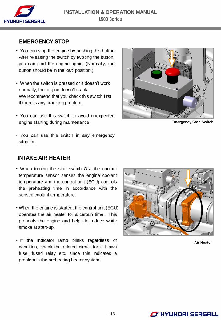
EMERGENCY STOP
INTAKE AIR HEATER
Emergency Stop Switch
• You can stop the engine by pushing this button.
After releasing the switch by twisting the button,
you can start the engine again. (Normally, the
button should be in the ‘out’ position.)
• When the switch is pressed or it doesn’t work
normally, the engine doesn’t crank.
We recommend that you check this switch first
if there is any cranking problem.
• You can use this switch to avoid unexpected
engine starting during maintenance.
• You can use this switch in any emergency
situation.
• When turning the start switch ON, the coolant
temperature sensor senses the engine coolant
temperature and the control unit (ECU) controls
the preheating time in accordance with the
sensed coolant temperature.
• When the engine is started, the control unit (ECU)
operates the air heater for a certain time. This
preheats the engine and helps to reduce white
smoke at start-up.
• If the indicator lamp blinks regardless of
condition, check the related circuit for a blown
fuse, fused relay etc. since this indicates a
problem in the preheating heater system.
Air Heater
- 16 -
INSTALLATION & OPERATION MANUAL
L500 Series
-17-
CHAPTER 3
COOLING SYSTEM
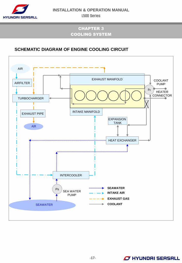
SCHEMATIC DIAGRAM OF ENGINE COOLING CIRCUIT
INTAKE MANIFOLD
Pc
COOLANT
PUMP
HEAT EXCHANGER
INTERCOOLER
TURBOCHARGER
AIRFILTER
SEA WATER
PUMP
SEAWATER
INTAKE AIR
EXHAUST GAS
COOLANT
HEATER
CONNECTOR
SEAWATER
EXPANSION
TANK
AIR
Ps
EXHAUST MANIFOLD
AIR
EXHAUST PIPE
INSTALLATION & OPERATION MANUAL
L500 Series
- 18 -
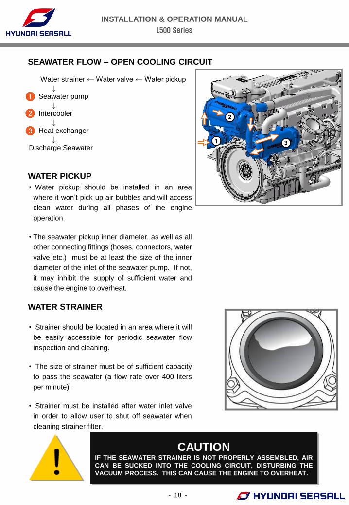
Water strainer ← Water valve ← Water pickup
↓
Seawater pump
↓
Intercooler
↓
Heat exchanger
↓
Discharge Seawater
SEAWATER FLOW – OPEN COOLING CIRCUIT
WATER PICKUP
• Water pickup should be installed in an area
where it won’t pick up air bubbles and will access
clean water during all phases of the engine
operation.
• The seawater pickup inner diameter, as well as all
other connecting fittings (hoses, connectors, water
valve etc.) must be at least the size of the inner
diameter of the inlet of the seawater pump. If not,
it may inhibit the supply of sufficient water and
cause the engine to overheat.
CAUTION IF THE SEAWATER STRAINER IS NOT PROPERLY ASSEMBLED, AIR
CAN BE SUCKED INTO THE COOLING CIRCUIT, DISTURBING THE
VACUUM PROCESS. THIS CAN CAUSE THE ENGINE TO OVERHEAT.
WATER STRAINER
• Strainer should be located in an area where it will
be easily accessible for periodic seawater flow
inspection and cleaning.
• The size of strainer must be of sufficient capacity
to pass the seawater (a flow rate over 400 liters
per minute).
• Strainer must be installed after water inlet valve
in order to allow user to shut off seawater when
cleaning strainer filter.
INSTALLATION & OPERATION MANUAL
L500 Series
- 19 -
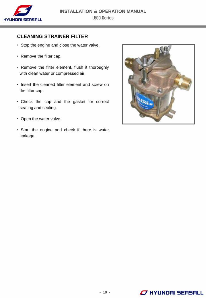
• Stop the engine and close the water valve.
• Remove the filter cap.
• Remove the filter element, flush it thoroughly
with clean water or compressed air.
• Insert the cleaned filter element and screw on
the filter cap.
• Check the cap and the gasket for correct
seating and sealing.
• Open the water valve.
• Start the engine and check if there is water
leakage.
CLEANING STRAINER FILTER
INSTALLATION & OPERATION MANUAL
L500 Series
- 20 -
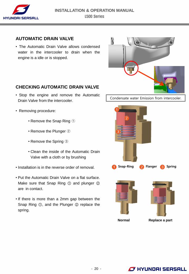
• The Automatic Drain Valve allows condensed
water in the intercooler to drain when the
engine is a idle or is stopped.
AUTOMATIC DRAIN VALVE
Snap-Ring Flanger Spring
CHECKING AUTOMATIC DRAIN VALVE
• Stop the engine and remove the Automatic
Drain Valve from the intercooler.
• Removing procedure:
• Remove the Snap Ring ①
• Remove the Plunger ②
• Remove the Spring ③
• Clean the inside of the Automatic Drain
Valve with a cloth or by brushing
• Installation is in the reverse order of removal.
• Put the Automatic Drain Valve on a flat surface.
Make sure that Snap Ring ① and plunger ②
are in contact.
• If there is more than a 2mm gap between the
Snap Ring ①, and the Plunger ② replace the
spring.
Condensate water Emission from intercooler.
Replace a part Normal
INSTALLATION & OPERATION MANUAL
L500 Series
- 21 -
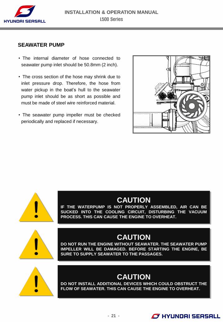
SEAWATER PUMP
• The internal diameter of hose connected to
seawater pump inlet should be 50.8mm (2 inch).
• The cross section of the hose may shrink due to
inlet pressure drop. Therefore, the hose from
water pickup in the boat’s hull to the seawater
pump inlet should be as short as possible and
must be made of steel wire reinforced material.
• The seawater pump impeller must be checked
periodically and replaced if necessary.
CAUTION IF THE WATERPUMP IS NOT PROPERLY ASSEMBLED, AIR CAN BE
SUCKED INTO THE COOLING CIRCUIT, DISTURBING THE VACUUM
PROCESS. THIS CAN CAUSE THE ENGINE TO OVERHEAT.
CAUTION DO NOT RUN THE ENGINE WITHOUT SEAWATER. THE SEAWATER PUMP
IMPELLER WILL BE DAMAGED. BEFORE STARTING THE ENGINE, BE
SURE TO SUPPLY SEAWATER TO THE PASSAGES.
CAUTION DO NOT INSTALL ADDITIONAL DEVICES WHICH COULD OBSTRUCT THE
FLOW OF SEAWATER. THIS CAN CAUSE THE ENGINE TO OVERHEAT.
INSTALLATION & OPERATION MANUAL
L500 Series
- 22 -
CAUTION DO NOT RUN THE ENGINE WITHOUT SEAWATER. THE SEAWATER
PUMP IMPELLER WILL BE DAMAGED. BEFORE STARTING THE
ENGINE, BE SURE TO SUPPLY SEAWATER TO THE PASSAGES.
CAUTION IMPELLER DAMAGE MAY OCCUR IF APPROPRIATE TOOLS ARE NOT
USED WHEN REMOVING THE IMPELLER. MAKE SURE TO CHECK O-
RING CONDITION AFTER SEAWATER PUMP REASSEMBLY.
CAUTION DO NOT INSTALL ADDITIONAL DEVICES WHICH COULD OBSTRUCT
THE FLOW OF SEAWATER. THIS CAN CAUSE THE ENGINE TO
OVERHEAT.
• Stop the engine and close the water valve.
• Remove the impeller housing cover.
• Remove the impeller from inside the seawater
pump.
• Check the condition of impeller and bushing.
• Apply soapy water to impeller when assembling,
and reassemble towards rotation direction.
• Replace the O-ring on the impeller housing
cover.
• Open the water valve.
• Start the engine and check if there is water
leakage.
CHECKING SEAWATER PUMP & IMPELLER
INSTALLATION & OPERATION MANUAL
L500 Series
- 23 -
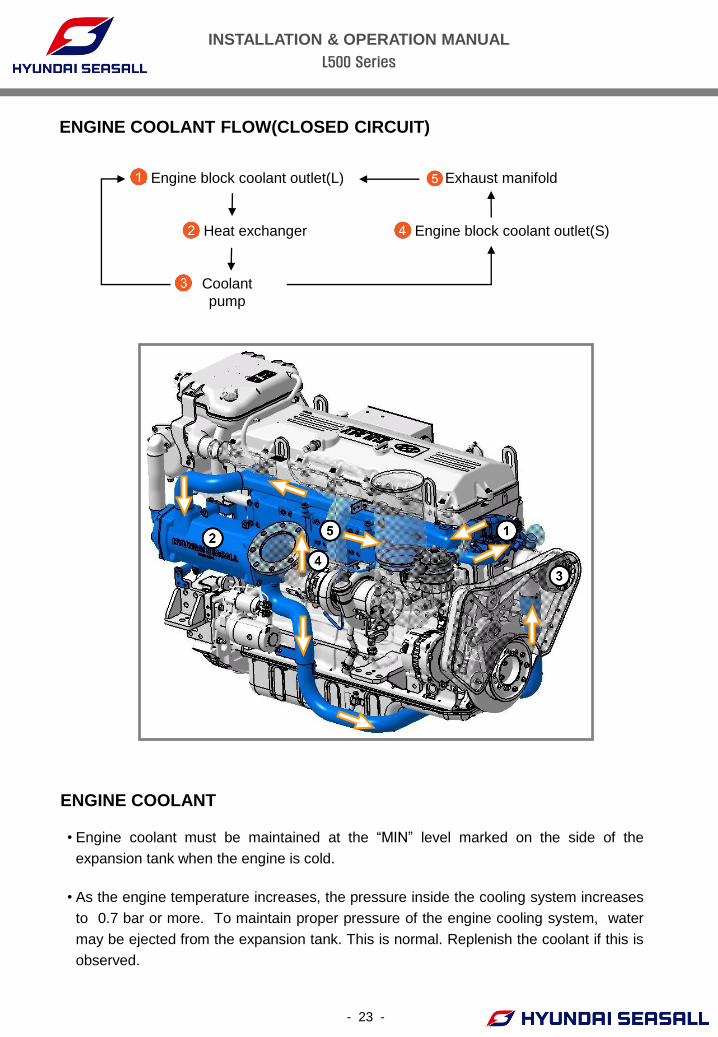
ENGINE COOLANT FLOW(CLOSED CIRCUIT)
• Engine coolant must be maintained at the “MIN” level marked on the side of the
expansion tank when the engine is cold.
• As the engine temperature increases, the pressure inside the cooling system increases
to 0.7 bar or more. To maintain proper pressure of the engine cooling system, water
may be ejected from the expansion tank. This is normal. Replenish the coolant if this is
observed.
ENGINE COOLANT
1. Engine block coolant outlet(L)
2. Heat exchanger
Coolant
pump
4. Engine block coolant outlet(S)
5. Exhaust manifold
INSTALLATION & OPERATION MANUAL
L500 Series
- 24 -
• If the coolant level is below level ‘Low’, add
enough specified coolant to provide protection
against freezing and corrosion. Coolant level
should be between the MAX and MIN. But do
not exceed level ‘MAX’.
• If frequent additions are required, contact an
authorized dealer for a cooling system
inspection.
• Use only soft (demineralized) water in the
coolant mixture.
• The engine has aluminum engine parts and
must be protected by an ethylene-glycol-based
coolant to prevent corrosion and freezing.
• DO NOT USE alcohol or methanol coolant or
mix them with the specified coolant.
• DO NOT USE a solution that contains more
than 60% antifreeze or less than 35% antifreeze,
which would reduce the effectiveness of the
solution. For mixture percentages, refer to the
table.
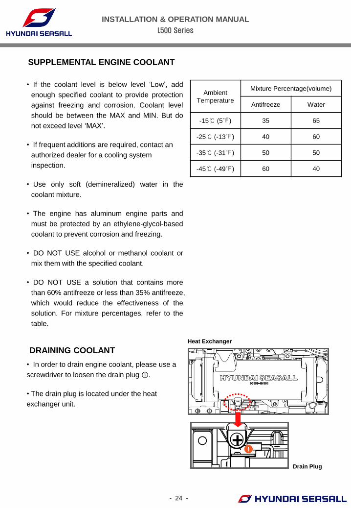
• In order to drain engine coolant, please use a
screwdriver to loosen the drain plug ①.
• The drain plug is located under the heat
exchanger unit.
DRAINING COOLANT
SUPPLEMENTAL ENGINE COOLANT
+ Drain Plug
Heat Exchanger
Ambient
Temperature
Mixture Percentage(volume)
Antifreeze Water
-15℃ (5℉) 35 65
-25℃ (-13℉) 40 60
-35℃ (-31℉) 50 50
-45℃ (-49℉) 60 40
INSTALLATION & OPERATION MANUAL
L500 Series
- 25 -
WARNING NEVER OPEN THE EXPANSION TANK CAP WHEN THE ENGINE IS
OPERATING OR HOT. IT COULD RESULT IN SERIOUS PERSONAL
INJURY AND MAY CAUSE ENGINE DAMAGE.
REMOVING AIR BUBBLES IN COOLANT
• Start the engine and warm it up at a low rpm.
• Stop the engine and allow the engine to cool,
then open the cap of the expansion tank
carefully.
*NOTE: Never open the cap when the engine is
hot. It may cause scalding.
• Refill with coolant if needed.
• Reinstall the expansion tank cap
• Check the level of the expansion tank regularly.
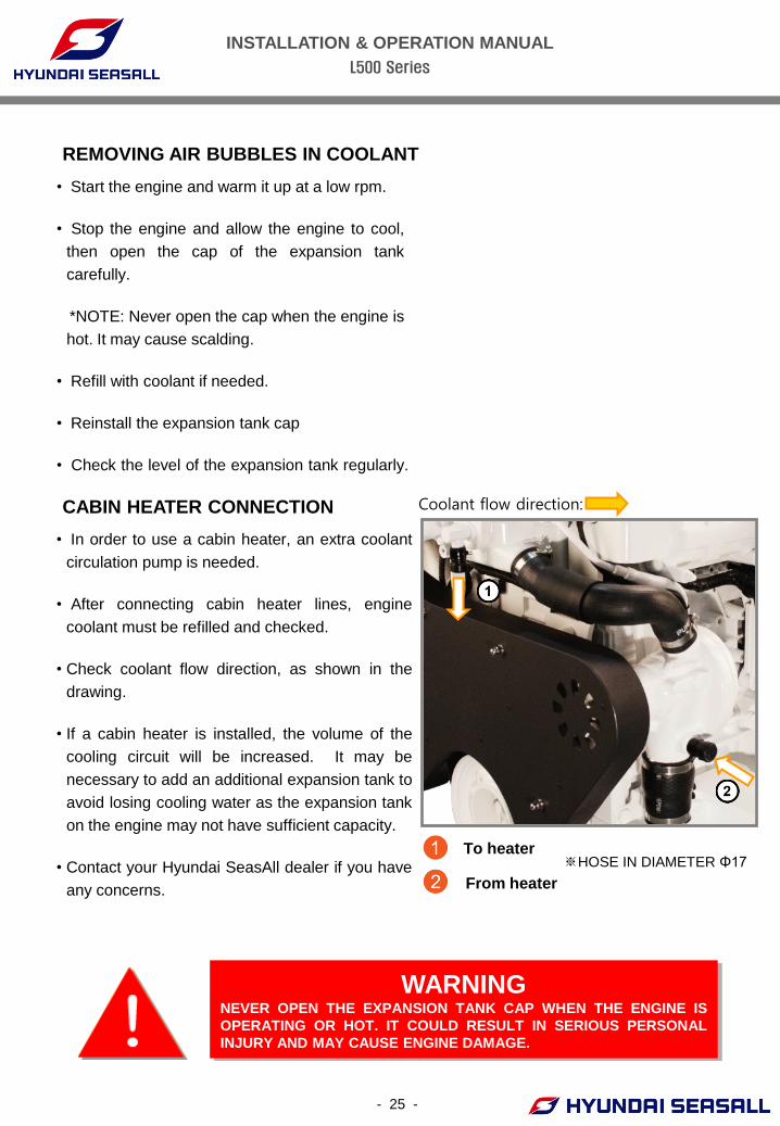
CABIN HEATER CONNECTION
• In order to use a cabin heater, an extra coolant
circulation pump is needed.
• After connecting cabin heater lines, engine
coolant must be refilled and checked.
• Check coolant flow direction, as shown in the
drawing.
• If a cabin heater is installed, the volume of the
cooling circuit will be increased. It may be
necessary to add an additional expansion tank to
avoid losing cooling water as the expansion tank
on the engine may not have sufficient capacity.
• Contact your Hyundai SeasAll dealer if you have
any concerns.
From heater
To heater ※HOSE IN DIAMETER Φ17
Coolant flow direction:
INSTALLATION & OPERATION MANUAL
L500 Series
- 26 -
CHAPTER 4
FUEL SYSTEM
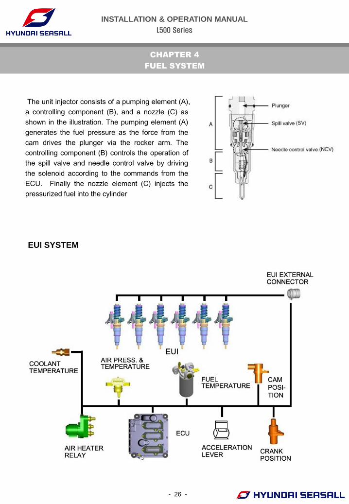
The unit injector consists of a pumping element (A),
a controlling component (B), and a nozzle (C) as
shown in the illustration. The pumping element (A)
generates the fuel pressure as the force from the
cam drives the plunger via the rocker arm. The
controlling component (B) controls the operation of
the spill valve and needle control valve by driving
the solenoid according to the commands from the
ECU. Finally the nozzle element (C) injects the
pressurized fuel into the cylinder
EUI SYSTEM
INSTALLATION & OPERATION MANUAL
L500 Series
- 27 -
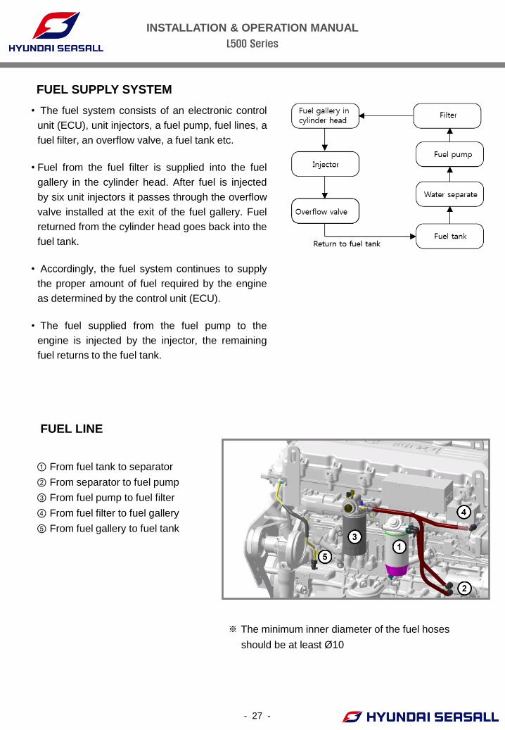
FUEL SUPPLY SYSTEM
FUEL LINE
① From fuel tank to separator
② From separator to fuel pump
③ From fuel pump to fuel filter
④ From fuel filter to fuel gallery
⑤ From fuel gallery to fuel tank
※ The minimum inner diameter of the fuel hoses
should be at least Ø 10
• The fuel system consists of an electronic control
unit (ECU), unit injectors, a fuel pump, fuel lines, a
fuel filter, an overflow valve, a fuel tank etc.
• Fuel from the fuel filter is supplied into the fuel
gallery in the cylinder head. After fuel is injected
by six unit injectors it passes through the overflow
valve installed at the exit of the fuel gallery. Fuel
returned from the cylinder head goes back into the
fuel tank.
• Accordingly, the fuel system continues to supply
the proper amount of fuel required by the engine
as determined by the control unit (ECU).
• The fuel supplied from the fuel pump to the
engine is injected by the injector, the remaining
fuel returns to the fuel tank.
INSTALLATION & OPERATION MANUAL
L500 Series
- 28 -
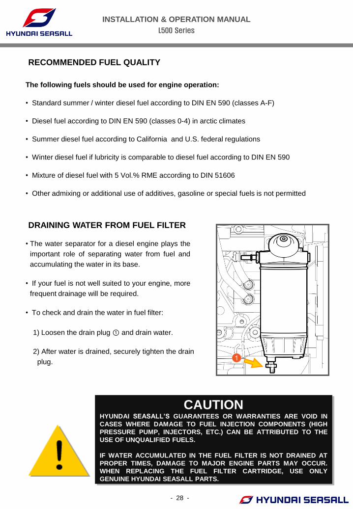
1) Loosen the drain plug ① and drain water.
2) After water is drained, securely tighten the drain
plug.
DRAINING WATER FROM FUEL FILTER
• The water separator for a diesel engine plays the
important role of separating water from fuel and
accumulating the water in its base.
• If your fuel is not well suited to your engine, more
frequent drainage will be required.
• To check and drain the water in fuel filter:
CAUTION HYUNDAI SEASALL’S GUARANTEES OR WARRANTIES ARE VOID IN
CASES WHERE DAMAGE TO FUEL INJECTION COMPONENTS (HIGH
PRESSURE PUMP, INJECTORS, ETC.) CAN BE ATTRIBUTED TO THE
USE OF UNQUALIFIED FUELS.
IF WATER ACCUMULATED IN THE FUEL FILTER IS NOT DRAINED AT
PROPER TIMES, DAMAGE TO MAJOR ENGINE PARTS MAY OCCUR.
WHEN REPLACING THE FUEL FILTER CARTRIDGE, USE ONLY
GENUINE HYUNDAI SEASALL PARTS.
The following fuels should be used for engine operation:
• Standard summer / winter diesel fuel according to DIN EN 590 (classes A-F)
• Diesel fuel according to DIN EN 590 (classes 0-4) in arctic climates
• Summer diesel fuel according to California and U.S. federal regulations
• Winter diesel fuel if lubricity is comparable to diesel fuel according to DIN EN 590
• Mixture of diesel fuel with 5 Vol.% RME according to DIN 51606
• Other admixing or additional use of additives, gasoline or special fuels is not permitted
RECOMMENDED FUEL QUALITY
INSTALLATION & OPERATION MANUAL
L500 Series
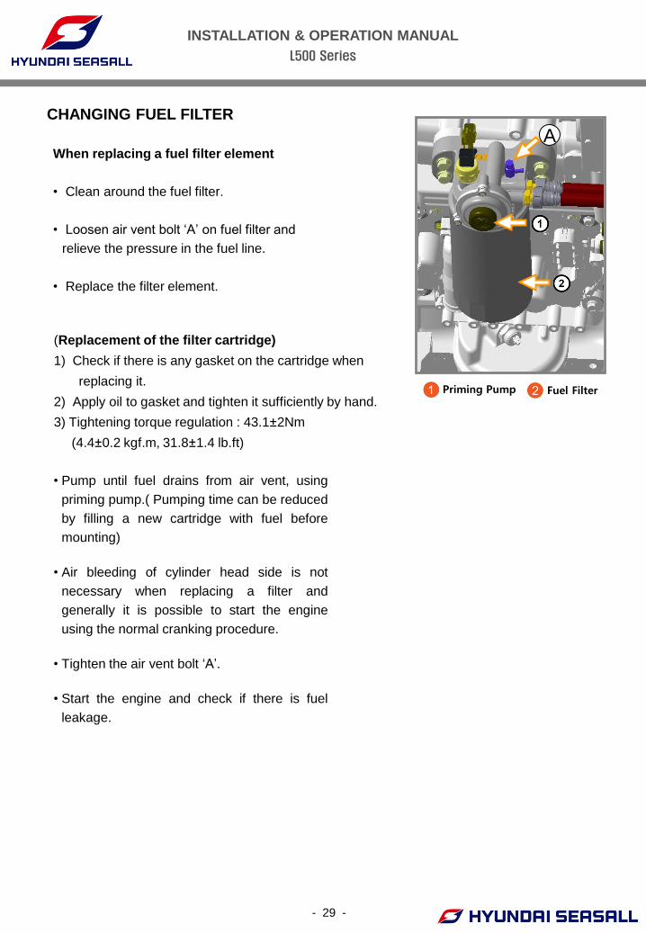
CHANGING FUEL FILTER
When replacing a fuel filter element
• Clean around the fuel filter.
• Loosen air vent bolt ‘A’ on fuel filter and
relieve the pressure in the fuel line.
• Replace the filter element.
(Replacement of the filter cartridge)
1) Check if there is any gasket on the cartridge when
replacing it.
2) Apply oil to gasket and tighten it sufficiently by hand.
3) Tightening torque regulation : 43.1±2Nm
(4.4±0.2 kgf.m, 31.8±1.4 lb.ft)
- 29 -
• Pump until fuel drains from air vent, using
priming pump.( Pumping time can be reduced
by filling a new cartridge with fuel before
mounting)
• Air bleeding of cylinder head side is not
necessary when replacing a filter and
generally it is possible to start the engine
using the normal cranking procedure.
• Tighten the air vent bolt ‘A’.
• Start the engine and check if there is fuel
leakage.
Fuel Filter Priming Pump
A
INSTALLATION & OPERATION MANUAL
L500 Series
- 30 -
CHAPTER 5
INTAKE & EXHAUST SYSTEM
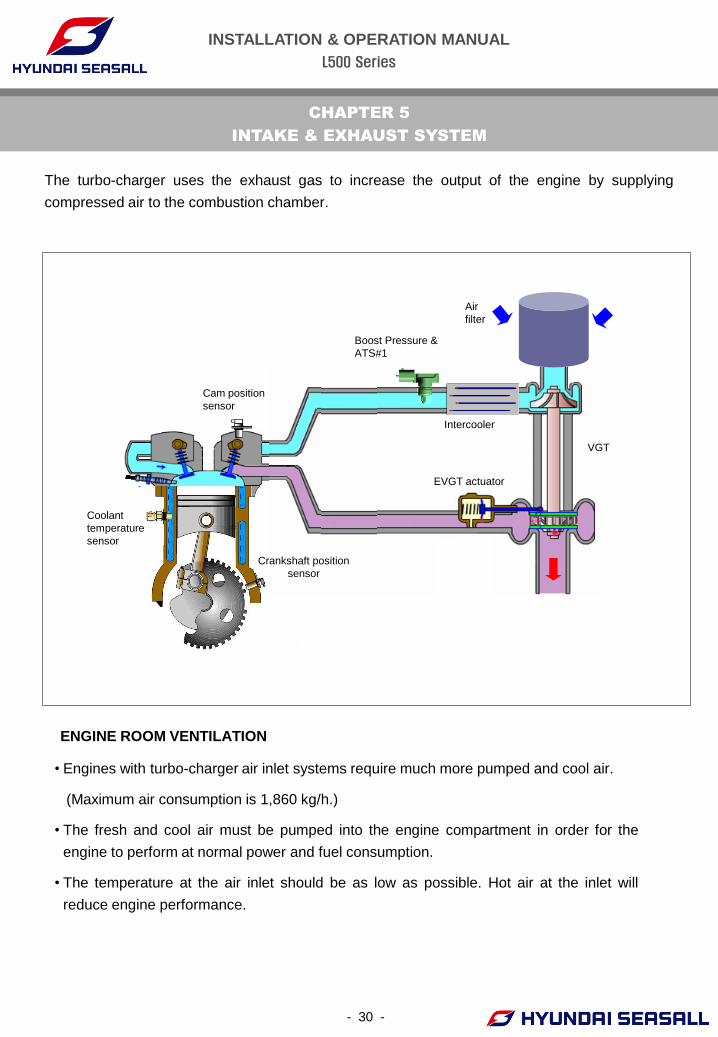
ENGINE ROOM VENTILATION
Boost Pressure &
ATS#1
Cam position
sensor
Crankshaft position
sensor
EVGT actuator
Intercooler
Air
filter
VGT
Coolant
temperature
sensor
The turbo-charger uses the exhaust gas to increase the output of the engine by supplying
compressed air to the combustion chamber.
• Engines with turbo-charger air inlet systems require much more pumped and cool air.
(Maximum air consumption is 1,860 kg/h.)
• The fresh and cool air must be pumped into the engine compartment in order for the
engine to perform at normal power and fuel consumption.
• The temperature at the air inlet should be as low as possible. Hot air at the inlet will
reduce engine performance.
INSTALLATION & OPERATION MANUAL
L500 Series
- 31 -
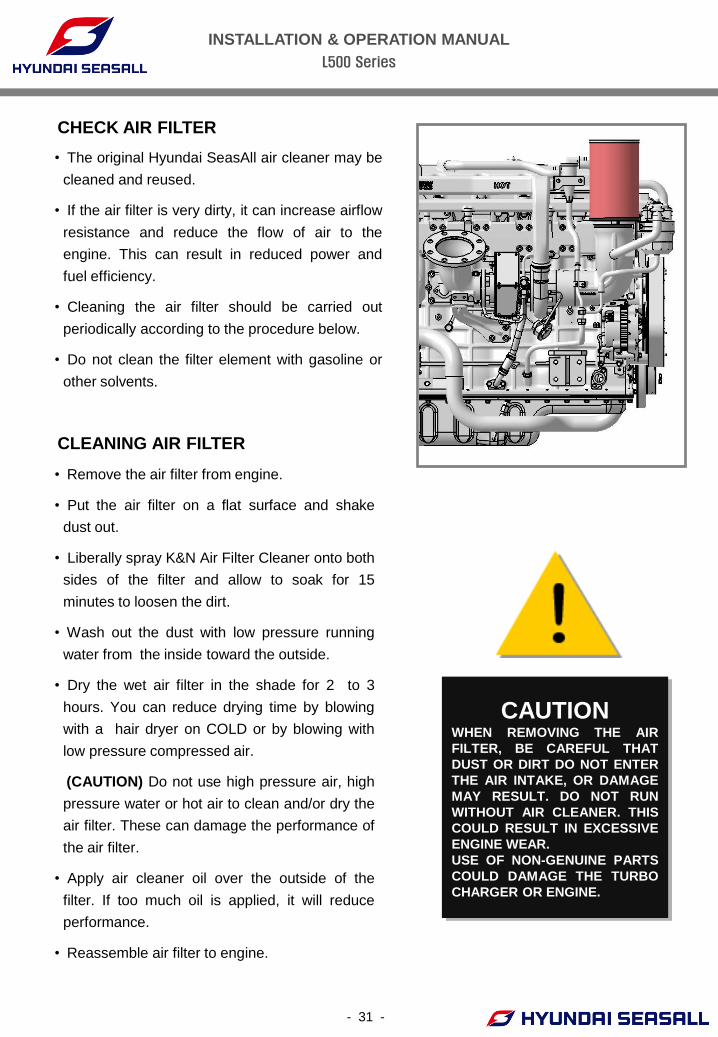
CHECK AIR FILTER
CLEANING AIR FILTER
CAUTION WHEN REMOVING THE AIR
FILTER, BE CAREFUL THAT
DUST OR DIRT DO NOT ENTER
THE AIR INTAKE, OR DAMAGE
MAY RESULT. DO NOT RUN
WITHOUT AIR CLEANER. THIS
COULD RESULT IN EXCESSIVE
ENGINE WEAR.
USE OF NON-GENUINE PARTS
COULD DAMAGE THE TURBO
CHARGER OR ENGINE.
• The original Hyundai SeasAll air cleaner may be
cleaned and reused.
• If the air filter is very dirty, it can increase airflow
resistance and reduce the flow of air to the
engine. This can result in reduced power and
fuel efficiency.
• Cleaning the air filter should be carried out
periodically according to the procedure below.
• Do not clean the filter element with gasoline or
other solvents.
• Remove the air filter from engine.
• Put the air filter on a flat surface and shake
dust out.
• Liberally spray K&N Air Filter Cleaner onto both
sides of the filter and allow to soak for 15
minutes to loosen the dirt.
• Wash out the dust with low pressure running
water from the inside toward the outside.
• Dry the wet air filter in the shade for 2 to 3
hours. You can reduce drying time by blowing
with a hair dryer on COLD or by blowing with
low pressure compressed air.
(CAUTION) Do not use high pressure air, high
pressure water or hot air to clean and/or dry the
air filter. These can damage the performance of
the air filter.
• Apply air cleaner oil over the outside of the
filter. If too much oil is applied, it will reduce
performance.
• Reassemble air filter to engine.
INSTALLATION & OPERATION MANUAL
L500 Series
- 32 -
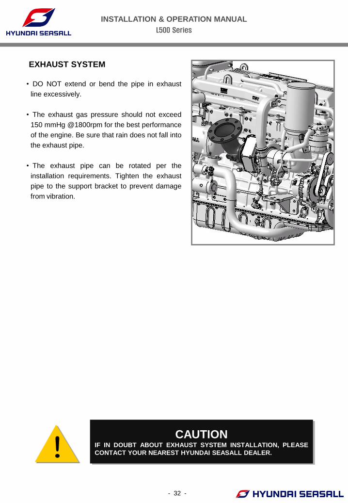
• DO NOT extend or bend the pipe in exhaust
line excessively.
• The exhaust gas pressure should not exceed
150 mmHg @1800rpm for the best performance
of the engine. Be sure that rain does not fall into
the exhaust pipe.
• The exhaust pipe can be rotated per the
installation requirements. Tighten the exhaust
pipe to the support bracket to prevent damage
from vibration.
EXHAUST SYSTEM
CAUTION IF IN DOUBT ABOUT EXHAUST SYSTEM INSTALLATION, PLEASE
CONTACT YOUR NEAREST HYUNDAI SEASALL DEALER.
INSTALLATION & OPERATION MANUAL
L500 Series
- 33 -
CHAPTER 6
LUBRICATION SYSTEM
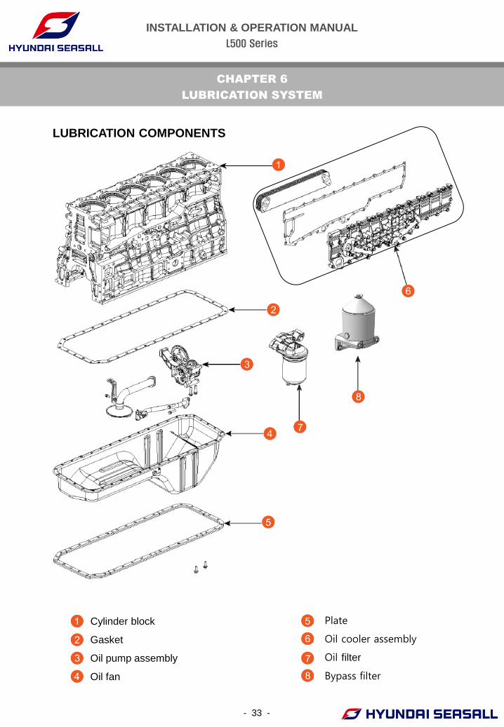
LUBRICATION COMPONENTS
1 Cylinder block
2. Gasket
3. Oil pump assembly
4. Oil fan
5. Plate
6. Oil cooler assembly
7. Oil filter
8. Bypass filter
INSTALLATION & OPERATION MANUAL
L500 Series
For best performance and maximum protection during all types of operation select only those
lubricants which :
• Satisfy the requirement of the API or ACEA classification.
• Have the proper SAE grade number for expected ambient temperature range.
- 34 -
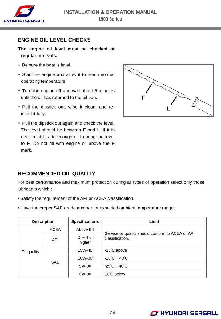
The engine oil level must be checked at
regular intervals.
• Be sure the boat is level.
• Start the engine and allow it to reach normal
operating temperature.
• Turn the engine off and wait about 5 minutes
until the oil has returned to the oil pan.
• Pull the dipstick out, wipe it clean, and re-
insert it fully.
• Pull the dipstick out again and check the level.
The level should be between F and L. If it is
near or at L, add enough oil to bring the level
to F. Do not fill with engine oil above the F
mark.
ENGINE OIL LEVEL CHECKS
RECOMMENDED OIL QUALITY
Description Specifications Limit
Oil quality
ACEA Above B4 Service oil quality should conform to ACEA or API
classification. API CI – 4 or
higher
SAE
15W-40 -15°C above
10W-30 -20°C ~ 40°C
5W-30 -25°C ~ 40°C
0W-30 10°C below
F
L
INSTALLATION & OPERATION MANUAL
L500 Series
- 35 -
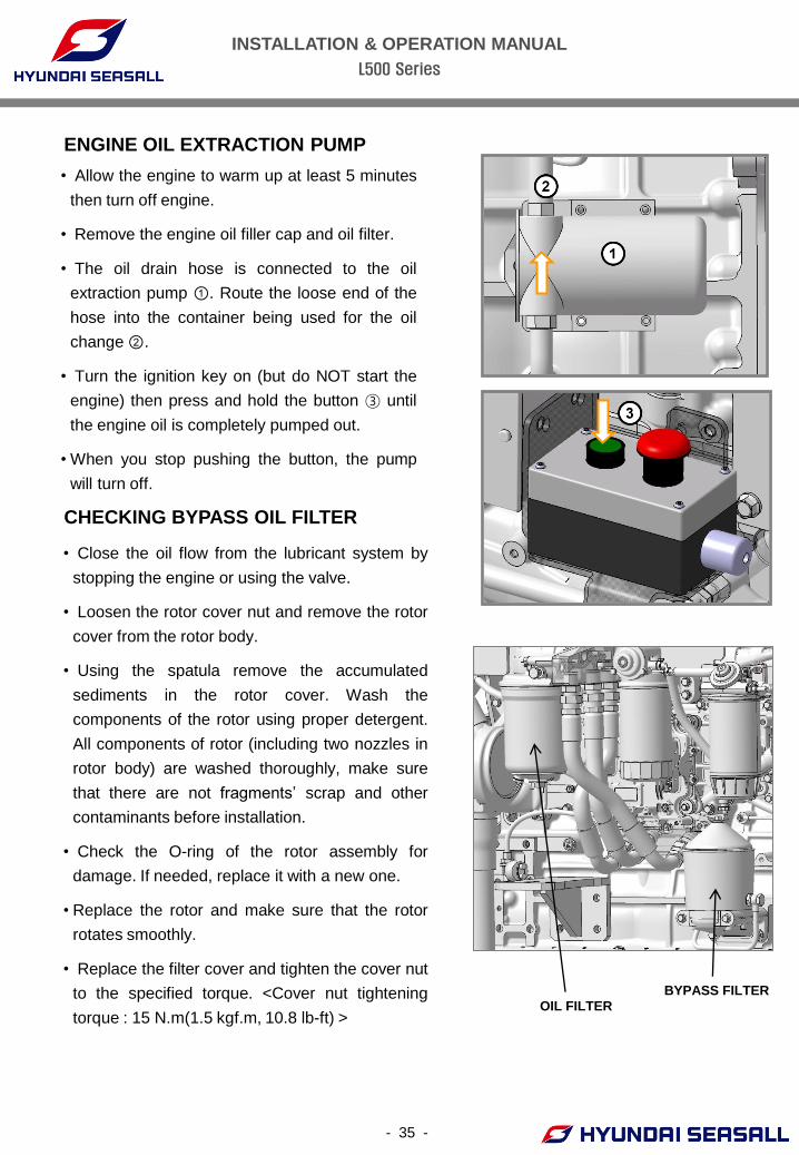
• Allow the engine to warm up at least 5 minutes
then turn off engine.
• Remove the engine oil filler cap and oil filter.
• The oil drain hose is connected to the oil
extraction pump ①. Route the loose end of the
hose into the container being used for the oil
change ②.
• Turn the ignition key on (but do NOT start the
engine) then press and hold the button ③ until
the engine oil is completely pumped out.
• When you stop pushing the button, the pump
will turn off.
ENGINE OIL EXTRACTION PUMP
CHECKING BYPASS OIL FILTER
• Close the oil flow from the lubricant system by
stopping the engine or using the valve.
• Loosen the rotor cover nut and remove the rotor
cover from the rotor body.
• Using the spatula remove the accumulated
sediments in the rotor cover. Wash the
components of the rotor using proper detergent.
All components of rotor (including two nozzles in
rotor body) are washed thoroughly, make sure
that there are not fragments’ scrap and other
contaminants before installation.
• Check the O-ring of the rotor assembly for
damage. If needed, replace it with a new one.
• Replace the rotor and make sure that the rotor
rotates smoothly.
• Replace the filter cover and tighten the cover nut
to the specified torque. <Cover nut tightening
torque : 15 N.m(1.5 kgf.m, 10.8 lb-ft) > OIL FILTER
BYPASS FILTER
INSTALLATION & OPERATION MANUAL
L500 Series
- 36 -
WARNING USED OIL MUST BE STORED IN A SAFE PLACE AWAY FROM CHILDREN
AND SOURCES OF IGNITION. IF YOU HAVE A USED OIL DISPOSAL
PROBLEM, PLEASE HAVE THE ENGINE OIL CHANGED BY YOUR NEAREST
HYUNDAI SEASALL SERVICE DEALER.
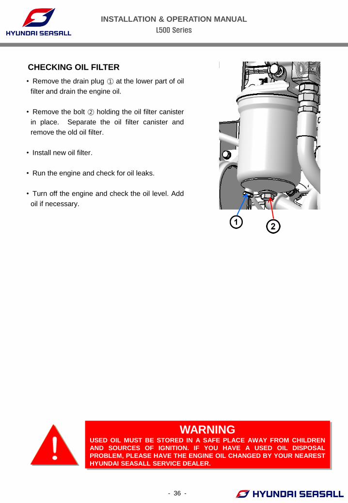
CHECKING OIL FILTER
• Remove the drain plug ① at the lower part of oil
filter and drain the engine oil.
• Remove the bolt ② holding the oil filter canister
in place. Separate the oil filter canister and
remove the old oil filter.
• Install new oil filter.
• Run the engine and check for oil leaks.
• Turn off the engine and check the oil level. Add
oil if necessary.
INSTALLATION & OPERATION MANUAL
L500 Series
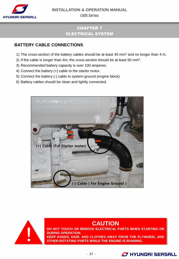
1) The cross-section of the battery cables should be at least 40 mm2 and no longer than 4 m.
2) If the cable is longer than 4m, the cross-section should be at least 50 mm2.
3) Recommended battery capacity is over 100 amperes.
4) Connect the battery (+) cable to the starter motor.
5) Connect the battery (-) cable to system ground (engine block).
6) Battery cables should be clean and tightly connected.
- 37 -
CHAPTER 7
ELECTRICAL SYSTEM
CAUTION DO NOT TOUCH OR REMOVE ELECTRICAL PARTS WHEN STARTING OR
DURING OPERATION.
KEEP HANDS, HAIR, AND CLOTHES AWAY FROM THE FLYWHEEL AND
OTHER ROTATING PARTS WHILE THE ENGINE IS RUNNING.
BATTERY CABLE CONNECTIONS
(-) Cable ( For Engine Ground )
(+) Cable (For Starter moter)
INSTALLATION & OPERATION MANUAL
L500 Series
- 38 -
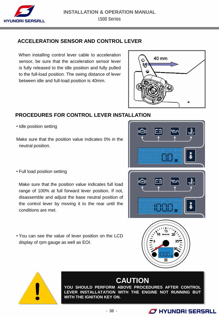
ACCELERATION SENSOR AND CONTROL LEVER
! CAUTION
YOU SHOULD PERFORM ABOVE PROCEDURES AFTER CONTROL
LEVER INSTALLATATION WITH THE ENGINE NOT RUNNING BUT
WITH THE IGNITION KEY ON.
40 mm
PROCEDURES FOR CONTROL LEVER INSTALLATION
When installing control lever cable to acceleration
sensor, be sure that the acceleration sensor lever
is fully released to the idle position and fully pulled
to the full-load position. The swing distance of lever
between idle and full-load position is 40mm.
• Idle position setting
Make sure that the position value indicates 0% in the
neutral position.
• Full load position setting
Make sure that the position value indicates full load
range of 100% at full forward lever position. If not,
disassemble and adjust the base neutral position of
the control lever by moving it to the rear until the
conditions are met.
• You can see the value of lever position on the LCD
display of rpm gauge as well as EOI.
INSTALLATION & OPERATION MANUAL
L500 Series
- 39 -
Battery inspection is very important in electronically controlled engines: You must check the
battery condition regularly.
BATTERY CHECKS
• Connect the load tester clamps to the terminals
and proceed with the test as follows:
CAUTION DO NOT LOOSEN OR DETACH BATTERY TERMINALS WHILE ENGINE IS
RUNNING. DOING SO WILL DAMAGE THE CHARGING SYSTEM AND
OTHER ELECTRONIC DEVICES.
WARNING BATTERY MUST BE STORED AND WORKED ON IN A SAFE PLACE
AWAY FROM CHILDREN AND SOURCES OF IGNITION.
FLUID IN THE BATTERY IS A CORROSIVE ACID AND MUST BE
HANDLED WITH CARE. IF SPILLED ON ANY PART OF THE BODY,
FLUSH IMMEDIATELY WITH WATER.
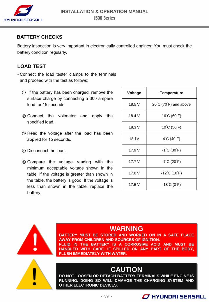
LOAD TEST
① If the battery has been charged, remove the
surface charge by connecting a 300 ampere
load for 15 seconds.
② Connect the voltmeter and apply the
specified load.
③ Read the voltage after the load has been
applied for 15 seconds.
④ Disconnect the load.
⑤ Compare the voltage reading with the
minimum acceptable voltage shown in the
table. If the voltage is greater than shown in
the table, the battery is good. If the voltage is
less than shown in the table, replace the
battery.
Voltage Temperature
18.5 V 20°C (70°F) and above
18.4 V 16°C (60°F)
18.3 V 10°C (50°F)
18.1V 4°C (40°F)
17.9 V -1°C (30°F)
17.7 V -7°C (20°F)
17.8 V -12°C (10°F)
17.5 V -18°C (0°F)
INSTALLATION & OPERATION MANUAL
L500 Series
- 40 -
FUSES AND RELAYS
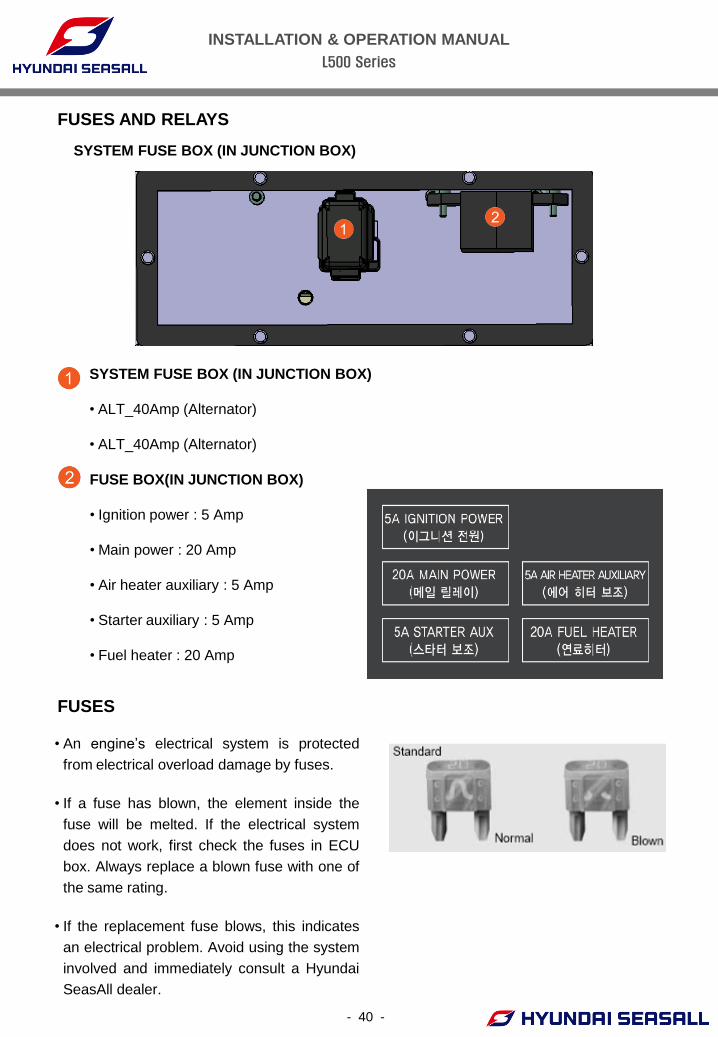
SYSTEM FUSE BOX (IN JUNCTION BOX)
SYSTEM FUSE BOX (IN JUNCTION BOX)
• ALT_40Amp (Alternator)
• ALT_40Amp (Alternator)
FUSE BOX(IN JUNCTION BOX)
• Ignition power : 5 Amp
• Main power : 20 Amp
• Air heater auxiliary : 5 Amp
• Starter auxiliary : 5 Amp
• Fuel heater : 20 Amp
FUSES
• An engine’s electrical system is protected
from electrical overload damage by fuses.
• If a fuse has blown, the element inside the
fuse will be melted. If the electrical system
does not work, first check the fuses in ECU
box. Always replace a blown fuse with one of
the same rating.
• If the replacement fuse blows, this indicates
an electrical problem. Avoid using the system
involved and immediately consult a Hyundai
SeasAll dealer.
INSTALLATION & OPERATION MANUAL
L500 Series
- 41 -
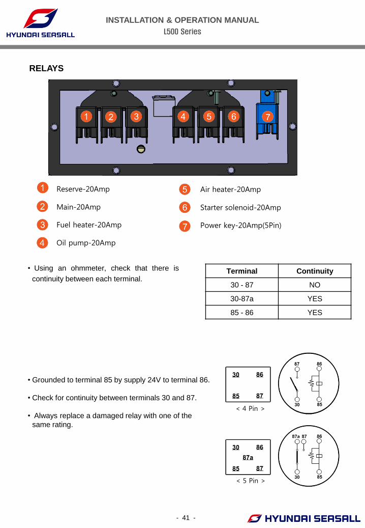
• Using an ohmmeter, check that there is
continuity between each terminal.
RELAYS
• Grounded to terminal 85 by supply 24V to terminal 86.
• Check for continuity between terminals 30 and 87.
• Always replace a damaged relay with one of the
same rating.
Terminal Continuity
30 - 87 NO
30-87a YES
85 - 86 YES
① Reserve-20Amp ⑦ Air heater-20Amp
② Main-20Amp ⑧ Starter solenoid-20Amp
③ Fuel heater-20Amp ⑨ Power key-20Amp(5Pin)
④ Oil pump-20Amp
< 4 Pin >
< 5 Pin >
INSTALLATION & OPERATION MANUAL
L500 Series
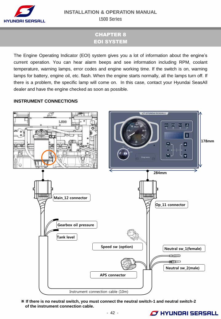
The Engine Operating Indicator (EOI) system gives you a lot of information about the engine’s
current operation. You can hear alarm beeps and see information including RPM, coolant
temperature, warning lamps, error codes and engine working time. If the switch is on, warning
lamps for battery, engine oil, etc. flash. When the engine starts normally, all the lamps turn off. If
there is a problem, the specific lamp will come on. In this case, contact your Hyundai SeasAll
dealer and have the engine checked as soon as possible.
CHAPTER 8
EOI SYSTEM
INSTRUMENT CONNECTIONS
- 42 -
284mm
178mm
※ If there is no neutral switch, you must connect the neutral switch-1 and neutral switch-2
of the instrument connection cable.
Instrument connection cable (10m)
APS connector
Main_12 connector
Gearbox oil pressure
Tank level
Op_11 connector
Neutral sw_2(male)
Neutral sw_1(female) Speed sw (option)
INSTALLATION & OPERATION MANUAL
L500 Series
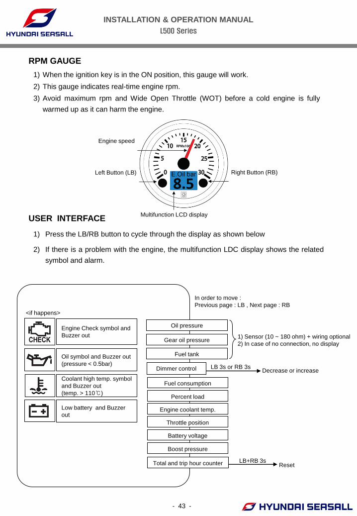
1) When the ignition key is in the ON position, this gauge will work.
2) This gauge indicates real-time engine rpm.
3) Avoid maximum rpm and Wide Open Throttle (WOT) before a cold engine is fully
warmed up as it can harm the engine.
RPM GAUGE
USER INTERFACE
- 43 -
Multifunction LCD display
Right Button (RB) Left Button (LB)
Engine speed
Decrease or increase
Fuel consumption
Engine coolant temp.
Throttle position
Battery voltage
Percent load
LB 3s or RB 3s
LB+RB 3s Reset
In order to move :
Previous page : LB , Next page : RB
Boost pressure
Oil pressure
Dimmer control
Total and trip hour counter
1) Sensor (10 ~ 180 ohm) + wiring optional
2) In case of no connection, no display
Fuel tank
Gear oil pressure
<if happens>
Engine Check symbol and
Buzzer out
Oil symbol and Buzzer out
(pressure < 0.5bar)
Coolant high temp. symbol
and Buzzer out
(temp. > 110℃)
Low battery and Buzzer
out
1) Press the LB/RB button to cycle through the display as shown below
2) If there is a problem with the engine, the multifunction LDC display shows the related
symbol and alarm.
INSTALLATION & OPERATION MANUAL
L500 Series
- 44 -
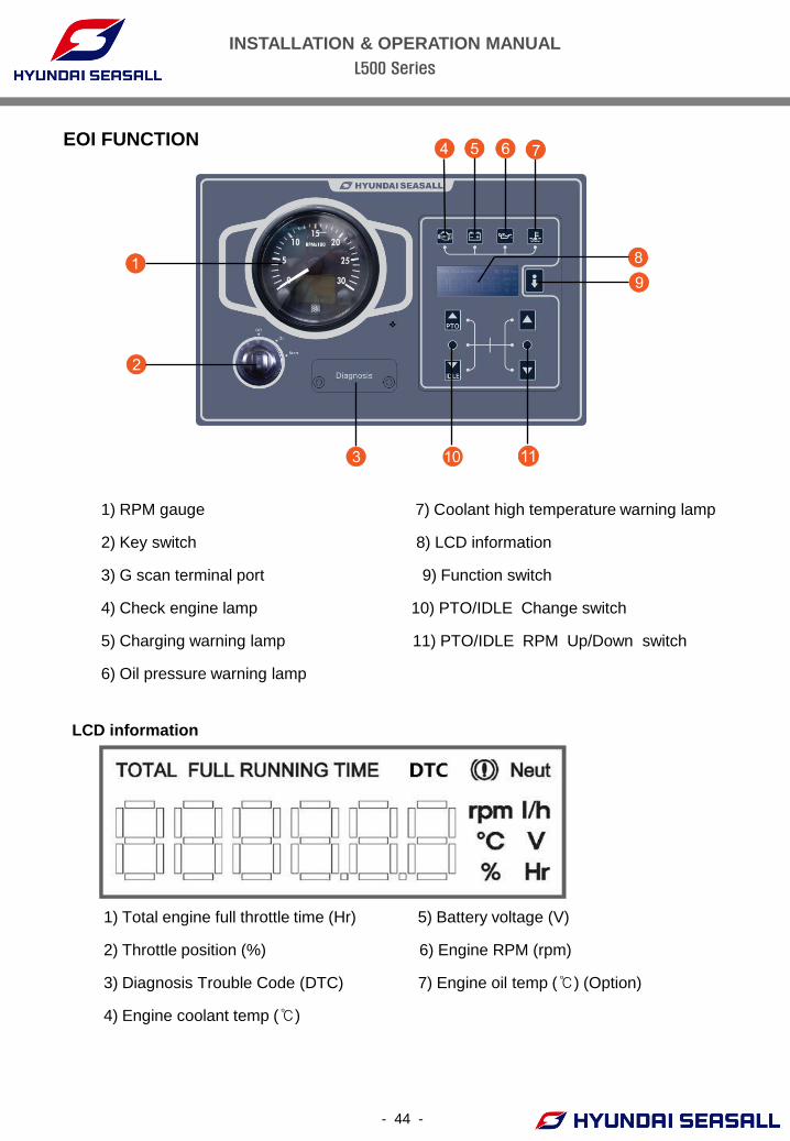
EOI FUNCTION
LCD information
1) RPM gauge 7) Coolant high temperature warning lamp
2) Key switch 8) LCD information
3) G scan terminal port 9) Function switch
4) Check engine lamp 10) PTO/IDLE Change switch
5) Charging warning lamp 11) PTO/IDLE RPM Up/Down switch
6) Oil pressure warning lamp
1) Total engine full throttle time (Hr) 5) Battery voltage (V)
2) Throttle position (%) 6) Engine RPM (rpm)
3) Diagnosis Trouble Code (DTC) 7) Engine oil temp (℃) (Option)
4) Engine coolant temp (℃)
INSTALLATION & OPERATION MANUAL
L500 Series
WARNING LAMPS
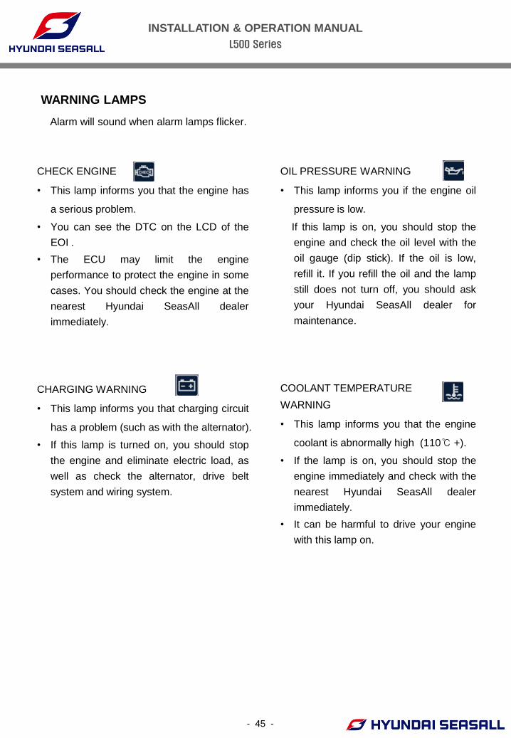
OIL PRESSURE WARNING
• This lamp informs you if the engine oil
pressure is low.
If this lamp is on, you should stop the
engine and check the oil level with the
oil gauge (dip stick). If the oil is low,
refill it. If you refill the oil and the lamp
still does not turn off, you should ask
your Hyundai SeasAll dealer for
maintenance.
COOLANT TEMPERATURE
WARNING
• This lamp informs you that the engine
coolant is abnormally high (110℃ +).
• If the lamp is on, you should stop the
engine immediately and check with the
nearest Hyundai SeasAll dealer
immediately.
• It can be harmful to drive your engine
with this lamp on.
CHECK ENGINE
• This lamp informs you that the engine has
a serious problem.
• You can see the DTC on the LCD of the
EOI .
• The ECU may limit the engine
performance to protect the engine in some
cases. You should check the engine at the
nearest Hyundai SeasAll dealer
immediately.
CHARGING WARNING
• This lamp informs you that charging circuit
has a problem (such as with the alternator).
• If this lamp is turned on, you should stop
the engine and eliminate electric load, as
well as check the alternator, drive belt
system and wiring system.
Alarm will sound when alarm lamps flicker.
- 45 -
INSTALLATION & OPERATION MANUAL
L500 Series
- 46 -
PTO MODE
IDLE SETTING MODE
1) Used to adjust the IDLE RPM.
2) Operate IDLE switch on Quiescent state.
3) When the switch moved to the UP or DOWN position, RPM value increases or decreases
by increments of 25 RPM.
4) When IDLE switch is OFF, IDLE RPM value will be returned to the initial RPM value.
5) Adjustable RPM area : 600RPM ~ 800RPM.
If you need to change the IDLE RPM value in the range of 600 RPM to 500 RPM, the
value can be changed using the G-SCAN. Contact your Hyundai-SeasAll dealer.
1) Function switch - use to change the information display on the LCD.
2) PTO/IDLE change switch – use to enable PTO/IDLE RPM adjustment function
3) UP/DOWN switch – use to raise or lower PTO/IDLE RPM.
SWITCHES
1) Used to adjust the fixed RPM of PTO.
2) When PTO switch is ON, engine speed will be upgraded 700RPM (initial RPM) .
3) You can adjust the RPM using the UP / DOWN switch.
4) When PTO switch is OFF, engine speed will be returned to the value set for IDLE RPM.
5) Adjustable RPM area : 700 RPM ~ 1900 RPM
INSTALLATION & OPERATION MANUAL
L500 Series
- 47 -
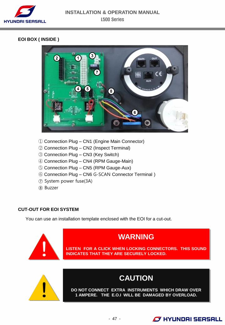
EOI BOX ( INSIDE )
WARNING
LISTEN FOR A CLICK WHEN LOCKING CONNECTORS. THIS SOUND
INDICATES THAT THEY ARE SECURELY LOCKED.
CAUTION
DO NOT CONNECT EXTRA INSTRUMENTS WHICH DRAW OVER
1 AMPERE. THE E.O.I WILL BE DAMAGED BY OVERLOAD.
① Connection Plug – CN1 (Engine Main Connector)
② Connection Plug – CN2 (Inspect Terminal)
③ Connection Plug – CN3 (Key Switch)
④ Connection Plug – CN4 (RPM Gauge-Main)
⑤ Connection Plug – CN5 (RPM Gauge-Aux)
⑥ Connection Plug – CN6 G-SCAN Connector Terminal )
⑦ System power fuse(3A)
⑧ Buzzer
CUT-OUT FOR EOI SYSTEM
You can use an installation template enclosed with the EOI for a cut-out.
INSTALLATION & OPERATION MANUAL
L500 Series
- 48 -
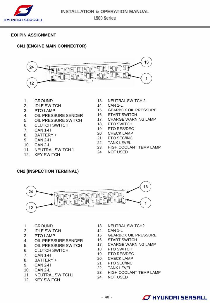
EOI PIN ASSIGNMENT
CN1 (ENGINE MAIN CONNECTOR)
CN2 (INSPECTION TERMINAL)
1. GROUND
2. IDLE SWITCH
3. PTO LAMP
4. OIL PRESSURE SENDER
5. OIL PRESSURE SWITCH
6. CLUTCH SWITCH
7. CAN 1-H
8. BATTERY +
9. CAN 2-H
10. CAN 2-L
11. NEUTRAL SWITCH 1
12. KEY SWITCH
13. NEUTRAL SWITCH 2
14. CAN 1-L
15. GEARBOX OIL PRESSURE
16. START SWITCH
17. CHARGE WARNING LAMP
18. PTO SWITCH
19. PTO RES/DEC
20. CHECK LAMP
21. PTO SEC/INC
22. TANK LEVEL
23. HIGH COOLANT TEMP LAMP
24. NOT USED
1. GROUND
2. IDLE SWITCH
3. PTO LAMP
4. OIL PRESSURE SENDER
5. OIL PRESSURE SWITCH
6. CLUTCH SWITCH
7. CAN 1-H
8. BATTERY +
9. CAN 2-H
10. CAN 2-L
11. NEUTRAL SWITCH1
12. KEY SWITCH
13. NEUTRAL SWITCH2
14. CAN 1-L
15. GEARBOX OIL PRESSURE
16. START SWITCH
17. CHARGE WARNING LAMP
18. PTO SWITCH
19. PTO RES/DEC
20. CHECK LAMP
21. PTO SEC/INC
22. TANK LEVEL
23. HIGH COOLANT TEMP LAMP
24. NOT USED
13
1
24
12
13
1
24
12
INSTALLATION & OPERATION MANUAL
L500 Series
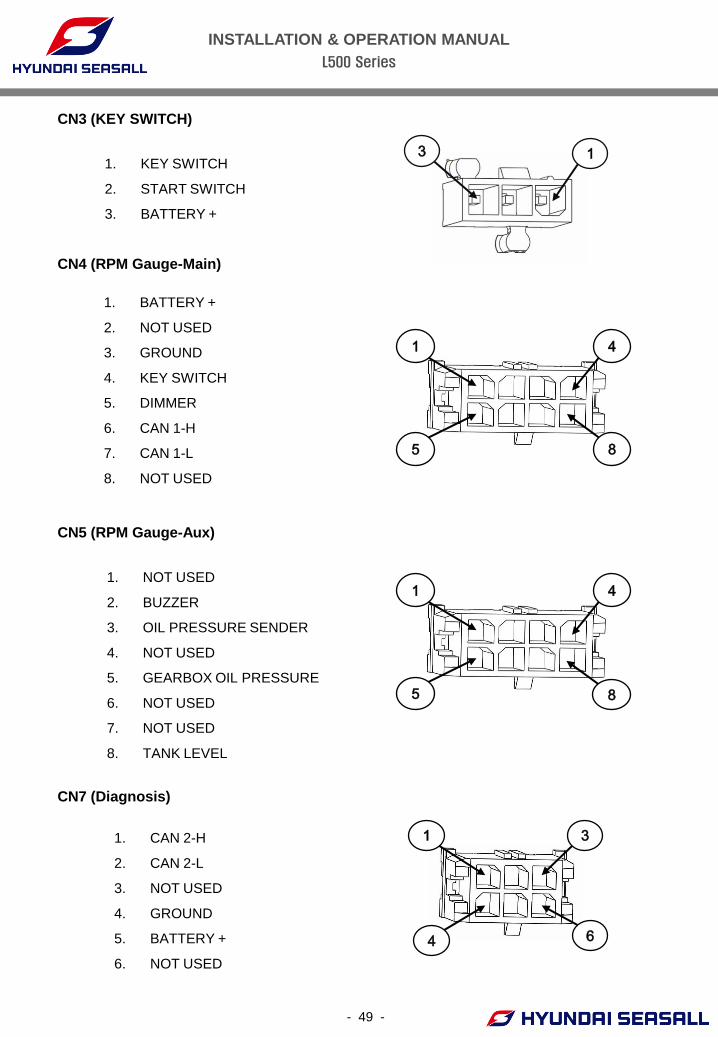
CN7 (Diagnosis)
1. CAN 2-H
2. CAN 2-L
3. NOT USED
4. GROUND
5. BATTERY +
6. NOT USED
1. KEY SWITCH
2. START SWITCH
3. BATTERY +
CN3 (KEY SWITCH)
1. BATTERY +
2. NOT USED
3. GROUND
4. KEY SWITCH
5. DIMMER
6. CAN 1-H
7. CAN 1-L
8. NOT USED
CN4 (RPM Gauge-Main)
CN5 (RPM Gauge-Aux)
1. NOT USED
2. BUZZER
3. OIL PRESSURE SENDER
4. NOT USED
5. GEARBOX OIL PRESSURE
6. NOT USED
7. NOT USED
8. TANK LEVEL
3 1
1 4
5 8
1 4
5 8
1
4
3
6
- 49 -
INSTALLATION & OPERATION MANUAL
L500 Series
50
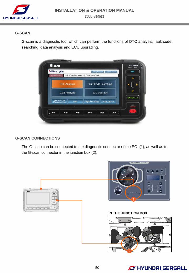
G-SCAN
G-scan is a diagnostic tool which can perform the functions of DTC analysis, fault code
searching, data analysis and ECU upgrading.
G-SCAN CONNECTIONS
The G-scan can be connected to the diagnostic connector of the EOI (1), as well as to
the G-scan connector in the junction box (2).
IN THE JUNCTION BOX
INSTALLATION & OPERATION MANUAL
L500 Series
- 51 -
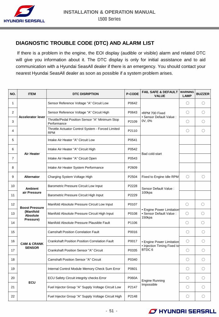
DIAGNOSTIC TROUBLE CODE (DTC) AND ALARM LIST
If there is a problem in the engine, the EOI display (audible or visible) alarm and related DTC
will give you information about it. The DTC display is only for initial assistance and to aid
communication with a Hyundai SeasAll dealer if there is an emergency. You should contact your
nearest Hyundai SeasAll dealer as soon as possible if a system problem arises.
NO. ITEM DTC DISRIPTION P-CODE FAIL SAFE & DEFAULT
VALUE
WARNING
LAMP BUZZER
1
Accelerator lever
Sensor Reference Voltage "A" Circuit Low P0642
▪RPM 700 Fixed
▪ Sensor Default Value :
0V, 0%
○ ○
2 Sensor Reference Voltage "A" Circuit High P0643 ○ ○
3 Throttle/Pedal Position Sensor "A" Minimum Stop
Performance P2109 ○ ○
4 Throttle Actuator Control System - Forced Limited
RPM P2110 ○ ○
5
Air Heater
Intake Air Heater "A" Circuit Low P0541
Bad cold-start
6 Intake Air Heater "A" Circuit High P0542
7 Intake Air Heater "A" Circuit Open P0543
8 Intake Air Heater System Performance P2609
9 Alternator Charging System Voltage High P2504 Fixed to Engine Idle RPM ○ ○
10 Ambient
air Pressure
Barometric Pressure Circuit Low Input P2228 Sensor Default Value :
100kpa
11 Barometric Pressure Circuit High Input P2229
12 Boost Pressure
(Manifold
Absolute
Pressure)
Manifold Absolute Pressure Circuit Low Input P0107
▪ Engine Power Limitation
▪ Sensor Default Value :
150kpa
○ ○
13 Manifold Absolute Pressure Circuit High Input P0108 ○ ○
14 Manifold Absolute Pressure Plausible Fault P1106 ○ ○
15
CAM & CRANK
SENSOR
Camshaft Position Correlation Fault P0016
▪ Engine Power Limitation
▪ Injection Timing Fixed to
BTDC 6
○ ○
16 Crankshaft Position Position Correlation Fault P0017 ○ ○
17 Crankshaft Position Sensor "A" Circuit P0335 ○ ○
18 Camshaft Position Sensor "A" Circuit P0340 ○ ○
19
ECU
Internal Control Module Memory Check Sum Error P0601
Engine Running
Impossible
○ ○
20 ECU Safety Circuit integrity checks Error P060A ○ ○
21 Fuel Injector Group "A" Supply Voltage Circuit Low P2147 ○ ○
22 Fuel Injector Group "A" Supply Voltage Circuit High P2148 ○ ○
INSTALLATION & OPERATION MANUAL
L500 Series
- 52 -
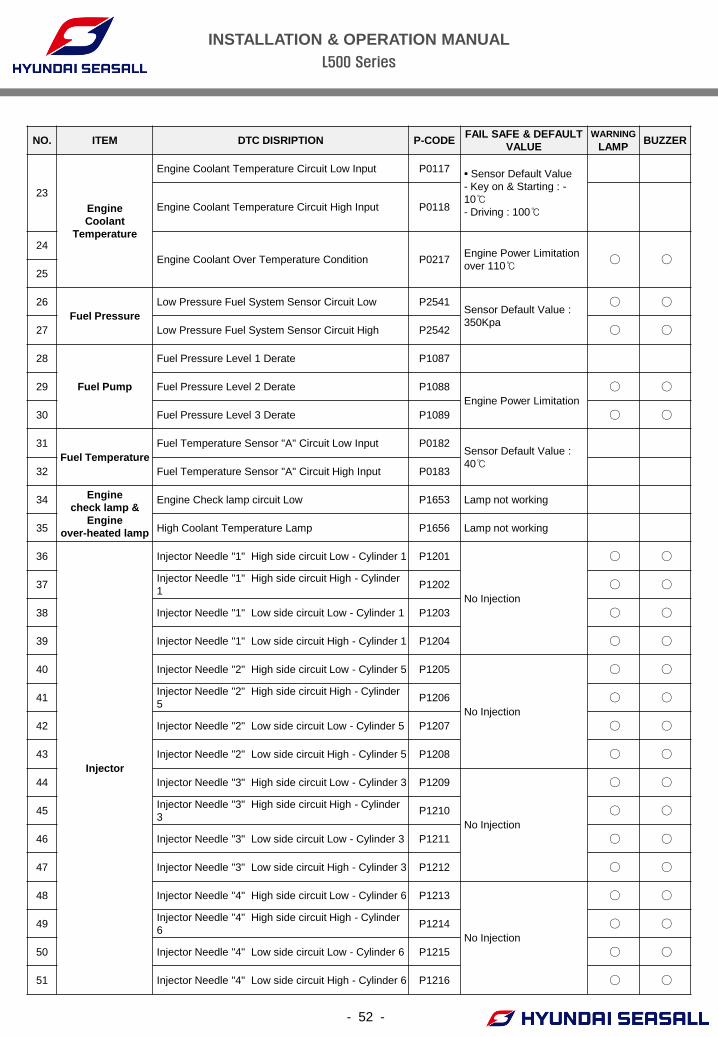
NO. ITEM DTC DISRIPTION P-CODE FAIL SAFE & DEFAULT
VALUE
WARNING
LAMP BUZZER
23
Engine
Coolant
Temperature
Engine Coolant Temperature Circuit Low Input P0117 ▪ Sensor Default Value
- Key on & Starting : -
10℃ - Driving : 100℃
Engine Coolant Temperature Circuit High Input P0118
24
Engine Coolant Over Temperature Condition P0217 Engine Power Limitation
over 110℃ ○ ○
25
26
Fuel Pressure
Low Pressure Fuel System Sensor Circuit Low P2541 Sensor Default Value :
350Kpa
○ ○
27 Low Pressure Fuel System Sensor Circuit High P2542 ○ ○
28
Fuel Pump
Fuel Pressure Level 1 Derate P1087
29 Fuel Pressure Level 2 Derate P1088
Engine Power Limitation
○ ○
30 Fuel Pressure Level 3 Derate P1089 ○ ○
31
Fuel Temperature
Fuel Temperature Sensor "A" Circuit Low Input P0182 Sensor Default Value :
40℃
32 Fuel Temperature Sensor "A" Circuit High Input P0183
34 Engine
check lamp &
Engine
over-heated lamp
Engine Check lamp circuit Low P1653 Lamp not working
35 High Coolant Temperature Lamp P1656 Lamp not working
36
Injector
Injector Needle "1" High side circuit Low - Cylinder 1 P1201
No Injection
○ ○
37 Injector Needle "1" High side circuit High - Cylinder
1 P1202 ○ ○
38 Injector Needle "1" Low side circuit Low - Cylinder 1 P1203 ○ ○
39 Injector Needle "1" Low side circuit High - Cylinder 1 P1204 ○ ○
40 Injector Needle "2" High side circuit Low - Cylinder 5 P1205
No Injection
○ ○
41 Injector Needle "2" High side circuit High - Cylinder
5 P1206 ○ ○
42 Injector Needle "2" Low side circuit Low - Cylinder 5 P1207 ○ ○
43 Injector Needle "2" Low side circuit High - Cylinder 5 P1208 ○ ○
44 Injector Needle "3" High side circuit Low - Cylinder 3 P1209
No Injection
○ ○
45 Injector Needle "3" High side circuit High - Cylinder
3 P1210 ○ ○
46 Injector Needle "3" Low side circuit Low - Cylinder 3 P1211 ○ ○
47 Injector Needle "3" Low side circuit High - Cylinder 3 P1212 ○ ○
48 Injector Needle "4" High side circuit Low - Cylinder 6 P1213
No Injection
○ ○
49 Injector Needle "4" High side circuit High - Cylinder
6 P1214 ○ ○
50 Injector Needle "4" Low side circuit Low - Cylinder 6 P1215 ○ ○
51 Injector Needle "4" Low side circuit High - Cylinder 6 P1216 ○ ○
INSTALLATION & OPERATION MANUAL
L500 Series
- 53 -
NO. ITEM DTC DISRIPTION P-CODE FAIL SAFE & DEFAULT
VALUE
WARNING
LAMP BUZZER
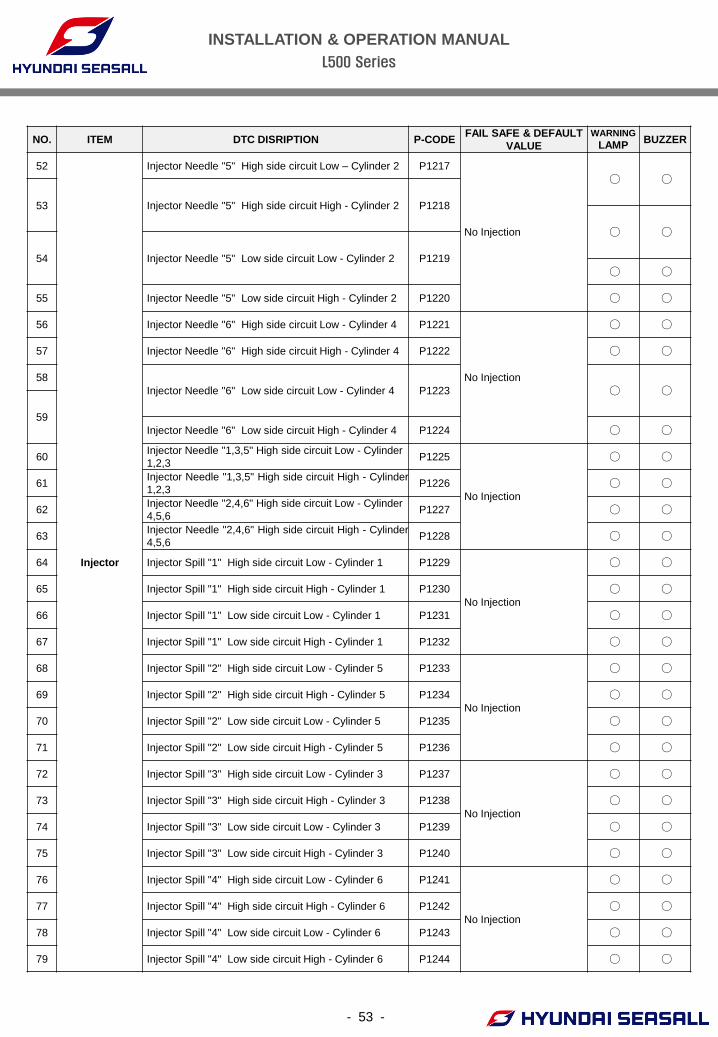
52
Injector
Injector Needle "5" High side circuit Low – Cylinder 2 P1217
No Injection
○ ○
53 Injector Needle "5" High side circuit High - Cylinder 2 P1218
○ ○
54 Injector Needle "5" Low side circuit Low - Cylinder 2 P1219
○ ○
55 Injector Needle "5" Low side circuit High - Cylinder 2 P1220 ○ ○
56 Injector Needle "6" High side circuit Low - Cylinder 4 P1221
No Injection
○ ○
57 Injector Needle "6" High side circuit High - Cylinder 4 P1222 ○ ○
58
Injector Needle "6" Low side circuit Low - Cylinder 4 P1223 ○ ○
59
Injector Needle "6" Low side circuit High - Cylinder 4 P1224 ○ ○
60 Injector Needle "1,3,5" High side circuit Low - Cylinder
1,2,3 P1225
No Injection
○ ○
61 Injector Needle "1,3,5" High side circuit High - Cylinder
1,2,3 P1226 ○ ○
62 Injector Needle "2,4,6" High side circuit Low - Cylinder
4,5,6 P1227 ○ ○
63 Injector Needle "2,4,6" High side circuit High - Cylinder
4,5,6 P1228 ○ ○
64 Injector Spill "1" High side circuit Low - Cylinder 1 P1229
No Injection
○ ○
65 Injector Spill "1" High side circuit High - Cylinder 1 P1230 ○ ○
66 Injector Spill "1" Low side circuit Low - Cylinder 1 P1231 ○ ○
67 Injector Spill "1" Low side circuit High - Cylinder 1 P1232 ○ ○
68 Injector Spill "2" High side circuit Low - Cylinder 5 P1233
No Injection
○ ○
69 Injector Spill "2" High side circuit High - Cylinder 5 P1234 ○ ○
70 Injector Spill "2" Low side circuit Low - Cylinder 5 P1235 ○ ○
71 Injector Spill "2" Low side circuit High - Cylinder 5 P1236 ○ ○
72 Injector Spill "3" High side circuit Low - Cylinder 3 P1237
No Injection
○ ○
73 Injector Spill "3" High side circuit High - Cylinder 3 P1238 ○ ○
74 Injector Spill "3" Low side circuit Low - Cylinder 3 P1239 ○ ○
75 Injector Spill "3" Low side circuit High - Cylinder 3 P1240 ○ ○
76 Injector Spill "4" High side circuit Low - Cylinder 6 P1241
No Injection
○ ○
77 Injector Spill "4" High side circuit High - Cylinder 6 P1242 ○ ○
78 Injector Spill "4" Low side circuit Low - Cylinder 6 P1243 ○ ○
79 Injector Spill "4" Low side circuit High - Cylinder 6 P1244 ○ ○
INSTALLATION & OPERATION MANUAL
L500 Series
54
NO. ITEM DTC DISRIPTION P-CODE FAIL SAFE & DEFAULT
VALUE
WARNING
LAMP BUZZER
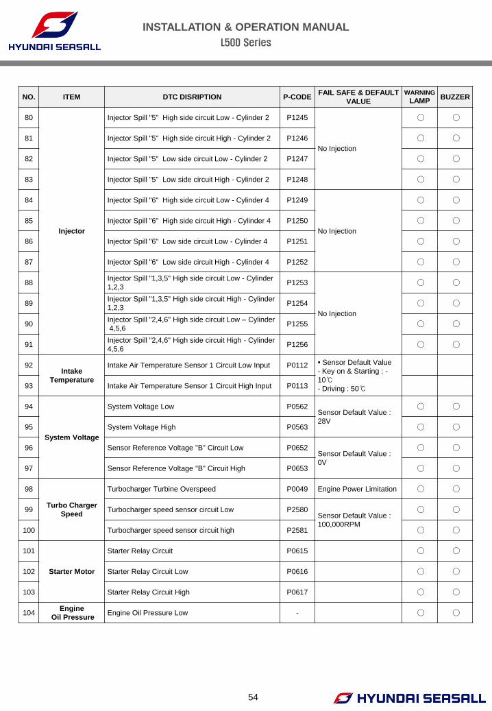
80
Injector
Injector Spill "5" High side circuit Low - Cylinder 2 P1245
No Injection
○ ○
81 Injector Spill "5" High side circuit High - Cylinder 2 P1246 ○ ○
82 Injector Spill "5" Low side circuit Low - Cylinder 2 P1247 ○ ○
83 Injector Spill "5" Low side circuit High - Cylinder 2 P1248 ○ ○
84 Injector Spill "6" High side circuit Low - Cylinder 4 P1249
No Injection
○ ○
85 Injector Spill "6" High side circuit High - Cylinder 4 P1250 ○ ○
86 Injector Spill "6" Low side circuit Low - Cylinder 4 P1251 ○ ○
87 Injector Spill "6" Low side circuit High - Cylinder 4 P1252 ○ ○
88 Injector Spill "1,3,5" High side circuit Low - Cylinder
1,2,3 P1253
No Injection
○ ○
89 Injector Spill "1,3,5" High side circuit High - Cylinder
1,2,3 P1254 ○ ○
90 Injector Spill "2,4,6" High side circuit Low – Cylinder
4,5,6 P1255 ○ ○
91 Injector Spill "2,4,6" High side circuit High - Cylinder
4,5,6 P1256 ○ ○
92 Intake
Temperature
Intake Air Temperature Sensor 1 Circuit Low Input P0112 ▪ Sensor Default Value
- Key on & Starting : -
10℃ - Driving : 50℃
93 Intake Air Temperature Sensor 1 Circuit High Input P0113
94
System Voltage
System Voltage Low P0562 Sensor Default Value :
28V
○ ○
95 System Voltage High P0563 ○ ○
96 Sensor Reference Voltage "B" Circuit Low P0652 Sensor Default Value :
0V
○ ○
97 Sensor Reference Voltage "B" Circuit High P0653 ○ ○
98
Turbo Charger
Speed
Turbocharger Turbine Overspeed P0049 Engine Power Limitation ○ ○
99 Turbocharger speed sensor circuit Low P2580 Sensor Default Value :
100,000RPM
○ ○
100 Turbocharger speed sensor circuit high P2581 ○ ○
101
Starter Motor
Starter Relay Circuit P0615 ○ ○
102 Starter Relay Circuit Low P0616 ○ ○
103 Starter Relay Circuit High P0617 ○ ○
104 Engine
Oil Pressure Engine Oil Pressure Low - ○ ○
INSTALLATION & OPERATION MANUAL
L500 Series
- 55 -
CHAPTER 9
ANTI CORROSION SYSTEM
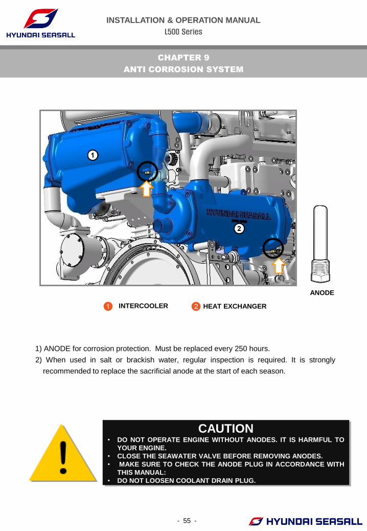
1) ANODE for corrosion protection. Must be replaced every 250 hours.
2) When used in salt or brackish water, regular inspection is required. It is strongly
recommended to replace the sacrificial anode at the start of each season.
ANODE
CAUTION • DO NOT OPERATE ENGINE WITHOUT ANODES. IT IS HARMFUL TO
YOUR ENGINE.
• CLOSE THE SEAWATER VALVE BEFORE REMOVING ANODES.
• MAKE SURE TO CHECK THE ANODE PLUG IN ACCORDANCE WITH
THIS MANUAL:
• DO NOT LOOSEN COOLANT DRAIN PLUG.
INTERCOOLER HEAT EXCHANGER
INSTALLATION & OPERATION MANUAL
L500 Series
- 56 -
CHAPTER 10
ENGINE STORAGE
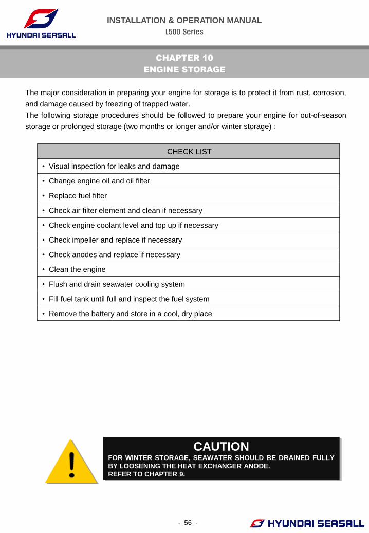
CAUTION FOR WINTER STORAGE, SEAWATER SHOULD BE DRAINED FULLY
BY LOOSENING THE HEAT EXCHANGER ANODE.
REFER TO CHAPTER 9.
The major consideration in preparing your engine for storage is to protect it from rust, corrosion,
and damage caused by freezing of trapped water.
The following storage procedures should be followed to prepare your engine for out-of-season
storage or prolonged storage (two months or longer and/or winter storage) :
CHECK LIST
• Visual inspection for leaks and damage
• Change engine oil and oil filter
• Replace fuel filter
• Check air filter element and clean if necessary
• Check engine coolant level and top up if necessary
• Check impeller and replace if necessary
• Check anodes and replace if necessary
• Clean the engine
• Flush and drain seawater cooling system
• Fill fuel tank until full and inspect the fuel system
• Remove the battery and store in a cool, dry place
INSTALLATION & OPERATION MANUAL
L500 Series
- 57 -
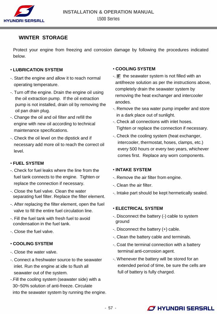
• LUBRICATION SYSTEM
-. Start the engine and allow it to reach normal
operating temperature.
-. Turn off the engine. Drain the engine oil using
the oil extraction pump. If the oil extraction
pump is not installed, drain oil by removing the
oil pan drain plug.
-. Change the oil and oil filter and refill the
engine with new oil according to technical
maintenance specifications.
-. Check the oil level on the dipstick and if
necessary add more oil to reach the correct oil
level.
• FUEL SYSTEM
-. Check for fuel leaks where the line from the
fuel tank connects to the engine. Tighten or
replace the connection if necessary.
-. Close the fuel valve. Clean the water
separating fuel filter. Replace the filter element.
-. After replacing the filter element, open the fuel
valve to fill the entire fuel circulation line.
-. Fill the fuel tank with fresh fuel to avoid
condensation in the fuel tank.
-. Close the fuel valve.
• COOLING SYSTEM
-. Close the water valve.
-. Connect a freshwater source to the seawater
inlet. Run the engine at idle to flush all
seawater out of the system.
-.Fill the cooling system (seawater side) with a
30~50% solution of anti-freeze. Circulate
into the seawater system by running the engine.
WINTER STORAGE
• COOLING SYSTEM
-. IF the seawater system is not filled with an
antifreeze solution as per the instructions above,
completely drain the seawater system by
removing the heat exchanger and intercooler
anodes.
-. Remove the sea water pump impeller and store
in a dark place out of sunlight.
-. Check all connections with inlet hoses.
Tighten or replace the connection if necessary.
-. Check the cooling system (heat exchanger,
intercooler, thermostat, hoses, clamps, etc.)
every 500 hours or every two years, whichever
comes first. Replace any worn components.
• INTAKE SYSTEM
-. Remove the air filter from engine.
-. Clean the air filter.
-. Intake part should be kept hermetically sealed.
• ELECTRICAL SYSTEM
-. Disconnect the battery (-) cable to system
ground
-. Disconnect the battery (+) cable.
-. Clean the battery cable and terminals.
-. Coat the terminal connection with a battery
terminal anti-corrosion agent.
-. Whenever the battery will be stored for an
extended period of time, be sure the cells are
full of battery is fully charged.
Protect your engine from freezing and corrosion damage by following the procedures indicated
below.
INSTALLATION & OPERATION MANUAL
L500 Series
- 58 -
CHAPTER 11
MAINTENANCE
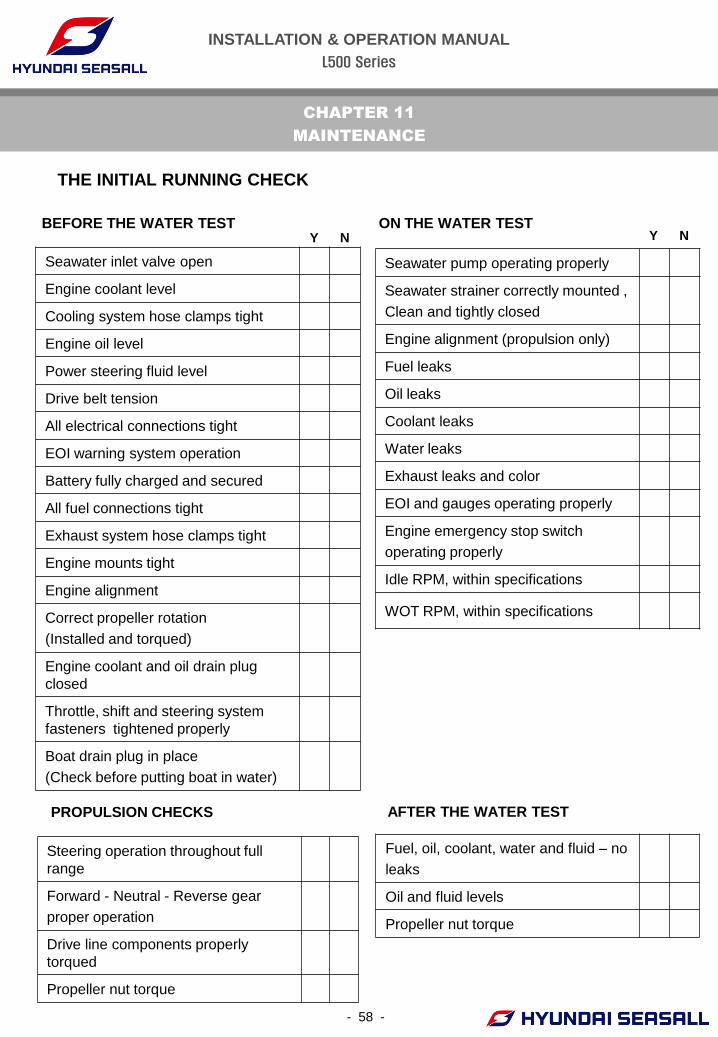
Seawater inlet valve open
Engine coolant level
Cooling system hose clamps tight
Engine oil level
Power steering fluid level
Drive belt tension
All electrical connections tight
EOI warning system operation
Battery fully charged and secured
All fuel connections tight
Exhaust system hose clamps tight
Engine mounts tight
Engine alignment
Correct propeller rotation
(Installed and torqued)
Engine coolant and oil drain plug
closed
Throttle, shift and steering system
fasteners tightened properly
Boat drain plug in place
(Check before putting boat in water)
Fuel, oil, coolant, water and fluid – no
leaks
Oil and fluid levels
Propeller nut torque
Steering operation throughout full
range
Forward - Neutral - Reverse gear
proper operation
Drive line components properly
torqued
Propeller nut torque
BEFORE THE WATER TEST ON THE WATER TEST
AFTER THE WATER TEST PROPULSION CHECKS
Y N Y N
Seawater pump operating properly
Seawater strainer correctly mounted ,
Clean and tightly closed
Engine alignment (propulsion only)
Fuel leaks
Oil leaks
Coolant leaks
Water leaks
Exhaust leaks and color
EOI and gauges operating properly
Engine emergency stop switch
operating properly
Idle RPM, within specifications
WOT RPM, within specifications
THE INITIAL RUNNING CHECK
INSTALLATION & OPERATION MANUAL
L500 Series
- 59 -
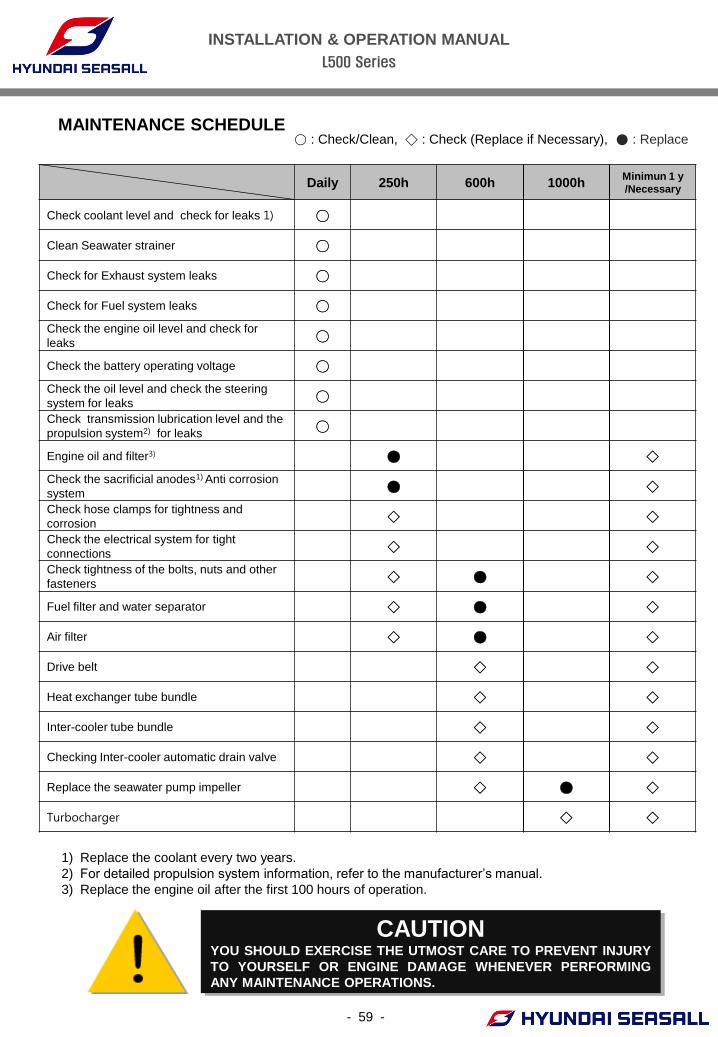
MAINTENANCE SCHEDULE
1) Replace the coolant every two years.
2) For detailed propulsion system information, refer to the manufacturer’s manual.
3) Replace the engine oil after the first 100 hours of operation.
CAUTION YOU SHOULD EXERCISE THE UTMOST CARE TO PREVENT INJURY
TO YOURSELF OR ENGINE DAMAGE WHENEVER PERFORMING
ANY MAINTENANCE OPERATIONS.
Daily 250h 600h 1000h Minimun 1 y
/Necessary
Check coolant level and check for leaks 1) ○
Clean Seawater strainer ○
Check for Exhaust system leaks ○
Check for Fuel system leaks ○
Check the engine oil level and check for
leaks ○
Check the battery operating voltage ○
Check the oil level and check the steering
system for leaks ○
Check transmission lubrication level and the
propulsion system2) for leaks ○
Engine oil and filter3) ● ◇
Check the sacrificial anodes1) Anti corrosion
system ● ◇
Check hose clamps for tightness and
corrosion ◇ ◇
Check the electrical system for tight
connections ◇ ◇
Check tightness of the bolts, nuts and other
fasteners ◇ ● ◇
Fuel filter and water separator ◇ ● ◇
Air filter ◇ ● ◇
Drive belt ◇ ◇
Heat exchanger tube bundle ◇ ◇
Inter-cooler tube bundle ◇ ◇
Checking Inter-cooler automatic drain valve ◇ ◇
Replace the seawater pump impeller ◇ ● ◇
Turbocharger ◇ ◇
○ : Check/Clean, ◇ : Check (Replace if Necessary), ● : Replace
INSTALLATION & OPERATION MANUAL
L500 Series
- 60 -
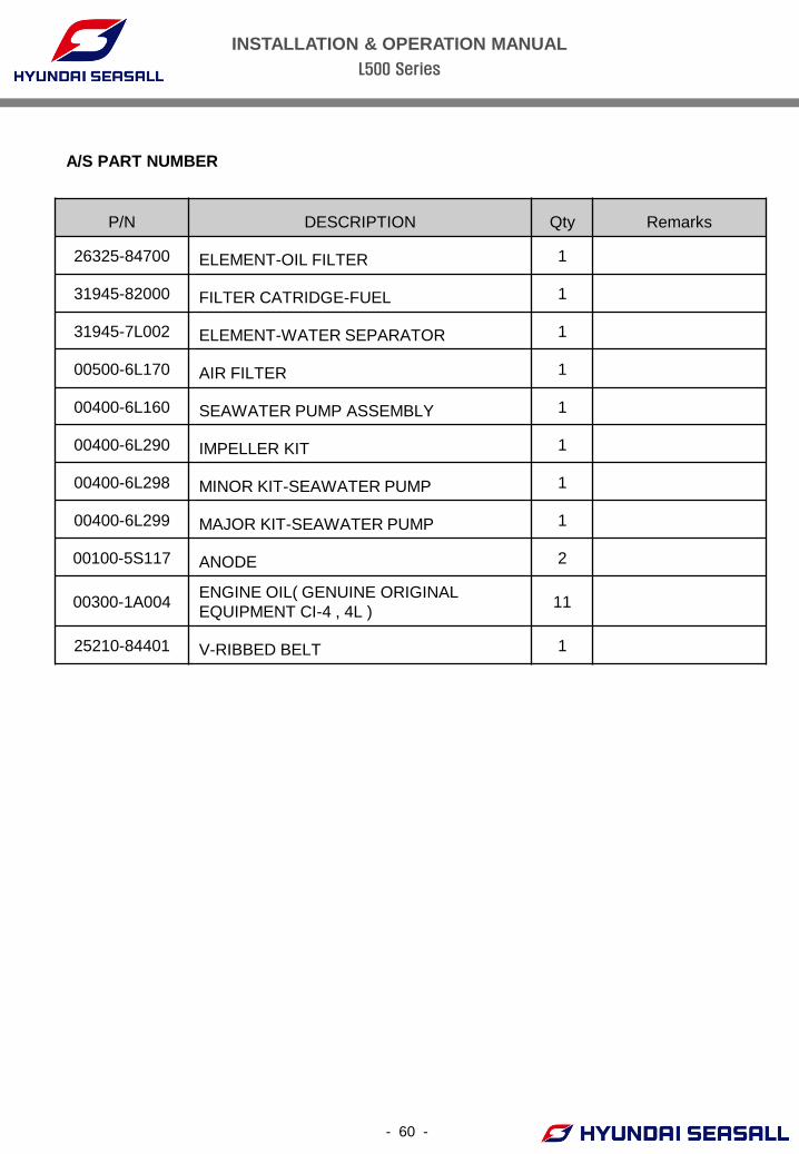
A/S PART NUMBER
P/N DESCRIPTION Qty Remarks
26325-84700 ELEMENT-OIL FILTER 1
31945-82000 FILTER CATRIDGE-FUEL 1
31945-7L002 ELEMENT-WATER SEPARATOR 1
00500-6L170 AIR FILTER 1
00400-6L160 SEAWATER PUMP ASSEMBLY 1
00400-6L290 IMPELLER KIT 1
00400-6L298 MINOR KIT-SEAWATER PUMP 1
00400-6L299 MAJOR KIT-SEAWATER PUMP 1
00100-5S117 ANODE 2
00300-1A004 ENGINE OIL( GENUINE ORIGINAL
EQUIPMENT CI-4 , 4L ) 11
25210-84401 V-RIBBED BELT 1
INSTALLATION & OPERATION MANUAL
L500 Series
- 61 -
MAINTENANCE LOG
DATE MAINTENANCE PERFORMED ENGINE HOURS
INSTALLATION & OPERATION MANUAL
L500 Series
- 62 -
CHAPTER 12
TROUBLESHOOTING GUIDE
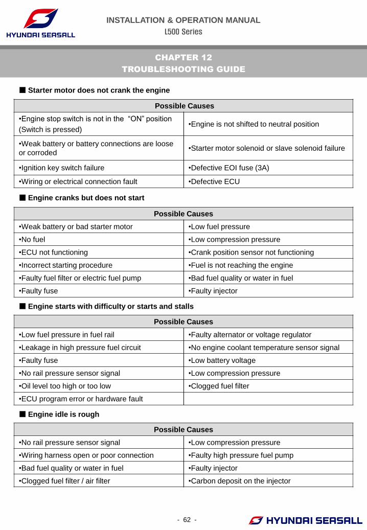
■ Starter motor does not crank the engine
Possible Causes
•Engine stop switch is not in the “ON” position
(Switch is pressed) •Engine is not shifted to neutral position
•Weak battery or battery connections are loose
or corroded •Starter motor solenoid or slave solenoid failure
•Ignition key switch failure •Defective EOI fuse (3A)
•Wiring or electrical connection fault •Defective ECU
■ Engine cranks but does not start
Possible Causes
•Weak battery or bad starter motor •Low fuel pressure
•No fuel •Low compression pressure
•ECU not functioning •Crank position sensor not functioning
•Incorrect starting procedure •Fuel is not reaching the engine
•Faulty fuel filter or electric fuel pump •Bad fuel quality or water in fuel
•Faulty fuse •Faulty injector
■ Engine starts with difficulty or starts and stalls
Possible Causes
•Low fuel pressure in fuel rail •Faulty alternator or voltage regulator
•Leakage in high pressure fuel circuit •No engine coolant temperature sensor signal
•Faulty fuse •Low battery voltage
•No rail pressure sensor signal •Low compression pressure
•Oil level too high or too low •Clogged fuel filter
•ECU program error or hardware fault
■ Engine idle is rough
Possible Causes
•No rail pressure sensor signal •Low compression pressure
•Wiring harness open or poor connection •Faulty high pressure fuel pump
•Bad fuel quality or water in fuel •Faulty injector
•Clogged fuel filter / air filter •Carbon deposit on the injector
INSTALLATION & OPERATION MANUAL
L500 Series
- 63 -
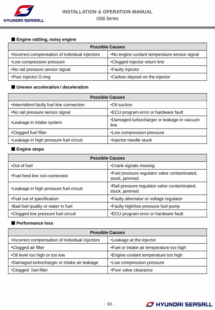
■ Engine rattling, noisy engine
Possible Causes
•Incorrect compensation of individual injectors •No engine coolant temperature sensor signal
•Low compression pressure •Clogged injector return line
•No rail pressure sensor signal •Faulty injector
•Poor injector O-ring •Carbon deposit on the injector
■ Uneven acceleration / deceleration
Possible Causes
•Intermittent faulty fuel line connection •Oil suction
•No rail pressure sensor signal •ECU program error or hardware fault
•Leakage in intake system •Damaged turbocharger or leakage in vacuum
line
•Clogged fuel filter •Low compression pressure
•Leakage in high pressure fuel circuit •Injector needle stuck
■ Engine stops
Possible Causes
•Out of fuel •Crank signals missing
•Fuel feed line not connected •Fuel pressure regulator valve contaminated,
stuck, jammed
•Leakage in high pressure fuel circuit •Rail pressure regulator valve contaminated,
stuck, jammed
•Fuel out of specification •Faulty alternator or voltage regulator
•Bad fuel quality or water in fuel •Faulty high/low pressure fuel pump
•Clogged low pressure fuel circuit •ECU program error or hardware fault
■ Performance loss
Possible Causes
•Incorrect compensation of individual injectors •Leakage at the injector
•Clogged air filter •Fuel or intake air temperature too high
•Oil level too high or too low •Engine coolant temperature too high
•Damaged turbocharger or intake air leakage •Low compression pressure
•Clogged fuel filter •Poor valve clearance
INSTALLATION & OPERATION MANUAL
L500 Series
- 64 -
CHAPTER 13
WARRANTY
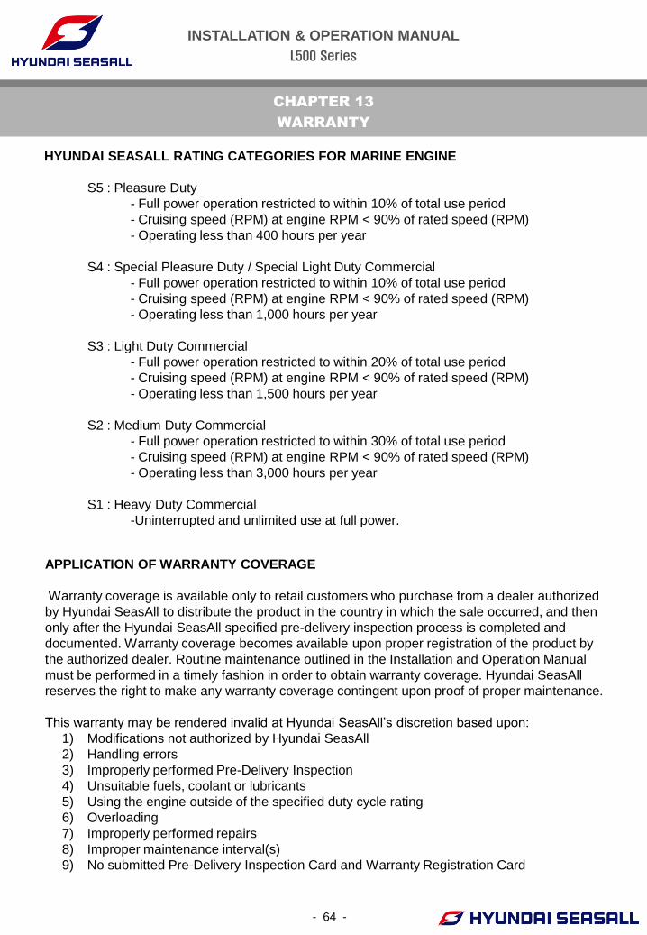
HYUNDAI SEASALL RATING CATEGORIES FOR MARINE ENGINE
S5 : Pleasure Duty
- Full power operation restricted to within 10% of total use period
- Cruising speed (RPM) at engine RPM < 90% of rated speed (RPM)
- Operating less than 400 hours per year
S4 : Special Pleasure Duty / Special Light Duty Commercial
- Full power operation restricted to within 10% of total use period
- Cruising speed (RPM) at engine RPM < 90% of rated speed (RPM)
- Operating less than 1,000 hours per year
S3 : Light Duty Commercial
- Full power operation restricted to within 20% of total use period
- Cruising speed (RPM) at engine RPM < 90% of rated speed (RPM)
- Operating less than 1,500 hours per year
S2 : Medium Duty Commercial
- Full power operation restricted to within 30% of total use period
- Cruising speed (RPM) at engine RPM < 90% of rated speed (RPM)
- Operating less than 3,000 hours per year
S1 : Heavy Duty Commercial
-Uninterrupted and unlimited use at full power.
APPLICATION OF WARRANTY COVERAGE
Warranty coverage is available only to retail customers who purchase from a dealer authorized
by Hyundai SeasAll to distribute the product in the country in which the sale occurred, and then
only after the Hyundai SeasAll specified pre-delivery inspection process is completed and
documented. Warranty coverage becomes available upon proper registration of the product by
the authorized dealer. Routine maintenance outlined in the Installation and Operation Manual
must be performed in a timely fashion in order to obtain warranty coverage. Hyundai SeasAll
reserves the right to make any warranty coverage contingent upon proof of proper maintenance.
This warranty may be rendered invalid at Hyundai SeasAll’s discretion based upon:
1) Modifications not authorized by Hyundai SeasAll
2) Handling errors
3) Improperly performed Pre-Delivery Inspection
4) Unsuitable fuels, coolant or lubricants
5) Using the engine outside of the specified duty cycle rating
6) Overloading
7) Improperly performed repairs
8) Improper maintenance interval(s)
9) No submitted Pre-Delivery Inspection Card and Warranty Registration Card
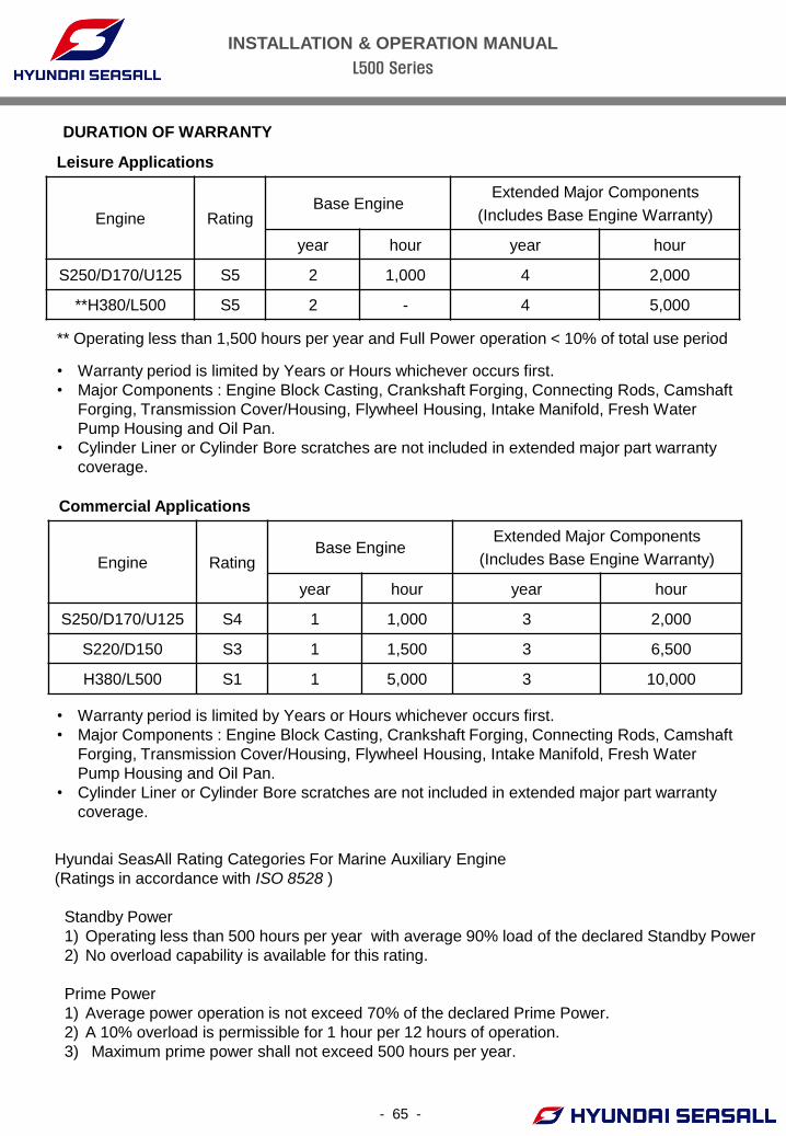
INSTALLATION & OPERATION MANUAL
L500 Series
- 65 -
DURATION OF WARRANTY
Leisure Applications
Engine Rating Base Engine
Extended Major Components
(Includes Base Engine Warranty)
year hour year hour
S250/D170/U125 S5 2 1,000 4 2,000
**H380/L500 S5 2 - 4 5,000
Commercial Applications
Engine Rating Base Engine
Extended Major Components
(Includes Base Engine Warranty)
year hour year hour
S250/D170/U125 S4 1 1,000 3 2,000
S220/D150 S3 1 1,500 3 6,500
H380/L500 S1 1 5,000 3 10,000
** Operating less than 1,500 hours per year and Full Power operation < 10% of total use period
• Warranty period is limited by Years or Hours whichever occurs first.
• Major Components : Engine Block Casting, Crankshaft Forging, Connecting Rods, Camshaft
Forging, Transmission Cover/Housing, Flywheel Housing, Intake Manifold, Fresh Water
Pump Housing and Oil Pan.
• Cylinder Liner or Cylinder Bore scratches are not included in extended major part warranty
coverage.
Hyundai SeasAll Rating Categories For Marine Auxiliary Engine
(Ratings in accordance with ISO 8528 )
Standby Power
1) Operating less than 500 hours per year with average 90% load of the declared Standby Power
2) No overload capability is available for this rating.
Prime Power
1) Average power operation is not exceed 70% of the declared Prime Power.
2) A 10% overload is permissible for 1 hour per 12 hours of operation.
3) Maximum prime power shall not exceed 500 hours per year.
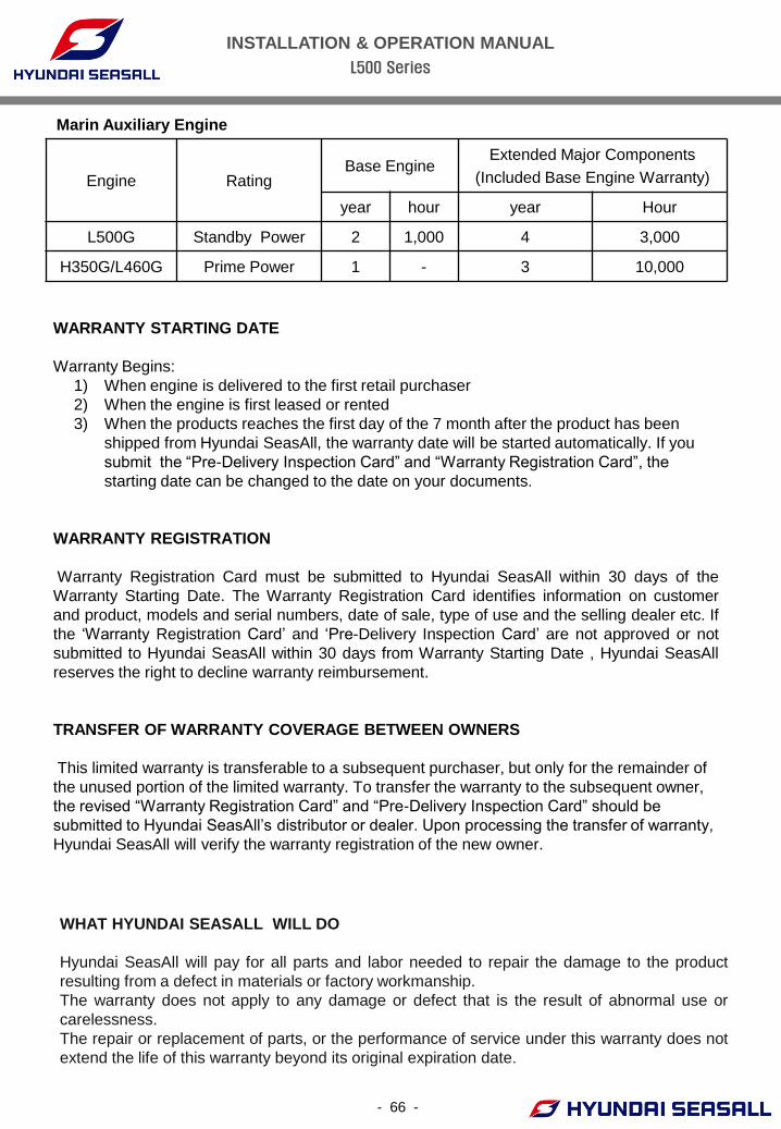
INSTALLATION & OPERATION MANUAL
L500 Series
- 66 -
Marin Auxiliary Engine
Engine Rating Base Engine
Extended Major Components
(Included Base Engine Warranty)
year hour year Hour
L500G Standby Power 2 1,000 4 3,000
H350G/L460G Prime Power 1 - 3 10,000
WARRANTY STARTING DATE
Warranty Begins:
1) When engine is delivered to the first retail purchaser
2) When the engine is first leased or rented
3) When the products reaches the first day of the 7 month after the product has been
shipped from Hyundai SeasAll, the warranty date will be started automatically. If you
submit the “Pre-Delivery Inspection Card” and “Warranty Registration Card”, the
starting date can be changed to the date on your documents.
WARRANTY REGISTRATION
Warranty Registration Card must be submitted to Hyundai SeasAll within 30 days of the
Warranty Starting Date. The Warranty Registration Card identifies information on customer
and product, models and serial numbers, date of sale, type of use and the selling dealer etc. If
the ‘Warranty Registration Card’ and ‘Pre-Delivery Inspection Card’ are not approved or not
submitted to Hyundai SeasAll within 30 days from Warranty Starting Date , Hyundai SeasAll
reserves the right to decline warranty reimbursement.
TRANSFER OF WARRANTY COVERAGE BETWEEN OWNERS
This limited warranty is transferable to a subsequent purchaser, but only for the remainder of
the unused portion of the limited warranty. To transfer the warranty to the subsequent owner,
the revised “Warranty Registration Card” and “Pre-Delivery Inspection Card” should be
submitted to Hyundai SeasAll’s distributor or dealer. Upon processing the transfer of warranty,
Hyundai SeasAll will verify the warranty registration of the new owner.
WHAT HYUNDAI SEASALL WILL DO
Hyundai SeasAll will pay for all parts and labor needed to repair the damage to the product
resulting from a defect in materials or factory workmanship.
The warranty does not apply to any damage or defect that is the result of abnormal use or
carelessness.
The repair or replacement of parts, or the performance of service under this warranty does not
extend the life of this warranty beyond its original expiration date.
INSTALLATION & OPERATION MANUAL
L500 Series
- 67 -
OWNER’S OBLIGATIONS
It is the owner’s obligation to install, operate, maintain and care for Hyundai SeasAll engines in
accordance with the instructions and requirements stated in the Installation and Operation
Manual.
The owner is responsible for providing enough time and cooperation to get the engine repaired
by an authorized dealer, and to deliver it to a proper facility for repair.
The owner is responsible for the cost for warranty inspection, including hauling out, launching
and transportation.
BUSINESS PARTNER’S OBLIGATIONS
It is Hyundai SeasAll’s Distributor and/or Dealer’s responsibility to support the retail customer
with prompt diagnosis and repair whether or not the engine was sold by the servicing dealer or
by the Distributor responsible for the territory.
It is Hyundai SeasAll’s Distributor’s responsibility to communicate all warranty issues to the
factory in a timely manner so that they can be quickly resolved.
HOW TO OBTAIN WARRANTY COVERAGE
The customer must provide Hyundai SeasAll with a reasonable opportunity to repair the engine,
as well as reasonable access to the product for warranty service. Warranty claims shall be
made to a Hyundai SeasAll Authorized Repair Facility to service the product. Purchaser shall
not, unless requested by Hyundai SeasAll, ship the product or parts of the product directly to
Hyundai SeasAll. The warranty registration card is the only valid registration identification and
must be presented to the dealer at the time warranty service is requested in order to obtain
coverage.
WHAT IS COVERED
Hyundai SeasAll warrants its products to be free of defects in material and workmanship during
the warranty period.
LIMITATIONS – EXPENDABLE PARTS
Not included are the following expendable parts:
• Filters : fuel filter, engine oil filter, air filter
• Lubricants : engine oil, coolant, power steering oil.
• Rubber products : seawater pump impeller, rubber hoses, belts, engine coupler, rubber
isolation mounts, bellows.
• Gaskets, anodes.
INSTALLATION & OPERATION MANUAL
L500 Series
- 68 -
WHAT IS NOT COVERED
• Fuel injector or filter cleaning
• Belt, cable adjustments or lubrication checks made in connection with normal services.
• Damage caused by neglect, lack of maintenance, accidents, abnormal operation, improper
installation or service, unapproved modifications or freezing temperatures.
• Haul-out (crane), launching or towing charges, removal and/or replacement of boat
partitions or material for necessary access to the product, all related transportation charges
and/or travel time, etc.
• All incidental and/or consequential damages (storage charges, telephone or rental charges
of any type, inconvenience or loss of time or income) are the owner’s responsibility.
• Use of other than Hyundai SeasAll genuine replacement parts when making warranty
repairs.
• Participating in or preparing for racing or other competitive activity.
• Water entering the engine via the air inlet filter or exhaust system or submersion. Water in
the starter motor.
• Failure of any parts caused by lack of cooling water.
• Damage caused by blockage of the cooling system by foreign matter.
• Use of fuels and lubricants that are not suitable for use with or on the product as specified
in the Installation and Operation Manual.
• Normal wear and tear
• Storage damage ( partially painting scratch )
• Cost resulting from ineffective or repeated repairs; improper repairs due to misdiagnosis.
• Owner’s personal cost ( indirect loss ) resulting from maintenance
TRANSMISSION AND STERNDRIVE WARRANTIES
Transmissions and drive systems (ZF Marine, Mercury etc.) are covered under separate
warranties, provided and serviced by those companies. For information on those warranties,
please see the separate booklets included in the original packaging of your Hyundai SeasAll
purchase.
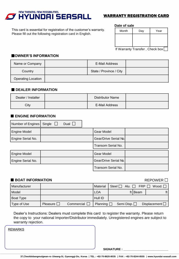
37,Cheoldobangmulgwan-ro Uiwang-Si, Gyeonggi-Do, Korea |TEL : +82-70-8620-8035 |FAX : +82-70-8244-8555 |www.hyundai-seasall.com
Date of sale
■ ENGINE INFORMATION
Engine Model Gear Model
Engine Serial No. Gear/Drive Serial No.
Transom Serial No.
Engine Model Gear Model
Engine Serial No. Gear/Drive Serial No.
Transom Serial No.
Number of Engines Single Dual
■ BOAT INFORMATION
Manufacturer Material Steel Alu. FRP Wood.
Model LOA ft Beam ft
Boat Type Hull ID
Type of Use Pleasure Commercial Planning Semi Disp. Displacement
REPOWER
Month Day Year
WARRANTY REGISTRATION CARD
This card is essential for registration of the customer’s warranty.
Please fill out the following registration card in English.
Dealer’s Instructions: Dealers must complete this card to register the warranty. Please return
the copy to your national Importer/Distributor immediately. Unregistered engines are subject to
warranty rejection.
If Warranty Transfer , Check box
Name or Company E-Mail Address
Country State / Province / City
Operating Location
■OWNER’S INFORMATION
Dealer / Installer Distributor Name
City E-Mail Address
■ DEALER INFORMATION
SIGNATURE : ___________________________
REMARKS
INSTALLATION & OPERATION MANUAL
L500 Series