Installation & Operation Manual for Energenics Air-Flow ... · PDF fileYaskawa V74X VFD...
14
1 1470 Don Street • Naples, Florida 34104 Telephone: (239) 643-1711 Fax: (239) 643-6081 Customer Service: (800) 944-1711 Installation & Operation Manual for Energenics Air-Flow Optimizer Table of Contents Page 1 Receiving and Installation Page 2 Description and Installation of Air-Flow Optimizer Page 3 Important Installation Considerations Page 4 Frequently asked technical questions Hitachi WJ200 Page 5 Frequently asked technical questions Yaskawa P-7 Page 6 Tubing Connections with Lint Filter Page 7 Tubing Connections without Lint Filter Page 8 Yaskawa P7 VFD (Inverter) Wiring Diagram W/Parameters (Enclosed Box) Page 9 Yaskawa P7 VFD (Inverter) Wiring Diagram W/Parameters (No Enclosure) Page 10 Yaskawa V74X VFD (Inverter) Parameters (No Enclosure) Page 11 Yaskawa V-1000 VFD (Inverter) Wiring Diagram W/Parameters (No Enclosure) Page 12 Hitachi WJ-200 VFD (Inverter) Wiring Diagram W/Parameters (2 – Wire) Page 13 Hitachi WJ-200 VFD (Inverter) Wiring Diagram W/Parameters (3 – Wire) Page 14
Transcript of Installation & Operation Manual for Energenics Air-Flow ... · PDF fileYaskawa V74X VFD...

1
1470 Don Street • Naples, Florida 34104 Telephone: (239) 643-1711 Fax: (239) 643-6081 Customer Service: (800) 944-1711
Installation & Operation Manual for Energenics Air-Flow Optimizer
Table of Contents Page 1
Receiving and Installation Page 2
Description and Installation of Air-Flow Optimizer Page 3
Important Installation Considerations Page 4
Frequently asked technical questions Hitachi WJ200 Page 5
Frequently asked technical questions Yaskawa P-7 Page 6
Tubing Connections with Lint Filter Page 7
Tubing Connections without Lint Filter Page 8
Yaskawa P7 VFD (Inverter) Wiring Diagram W/Parameters (Enclosed Box) Page 9
Yaskawa P7 VFD (Inverter) Wiring Diagram W/Parameters (No Enclosure) Page 10
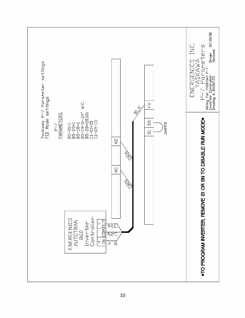
Yaskawa V74X VFD (Inverter) Parameters (No Enclosure) Page 11
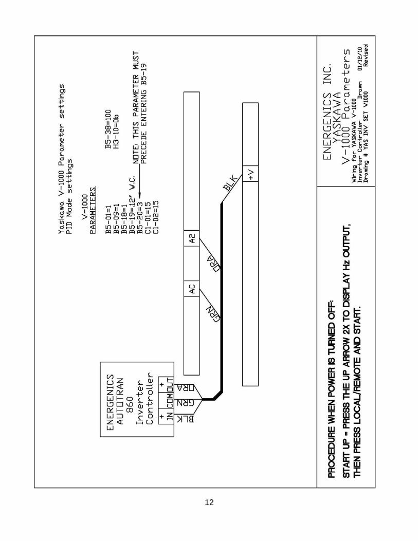
Yaskawa V-1000 VFD (Inverter) Wiring Diagram W/Parameters (No Enclosure) Page 12
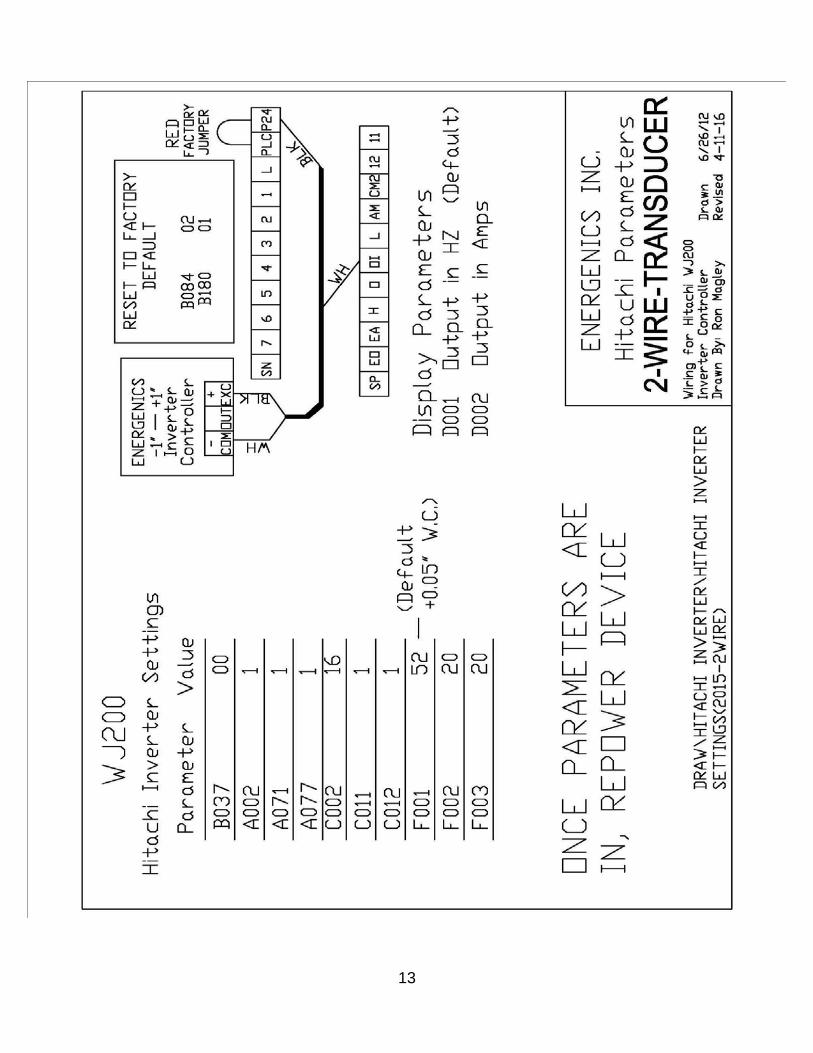
Hitachi WJ-200 VFD (Inverter) Wiring Diagram W/Parameters (2 – Wire) Page 13
Hitachi WJ-200 VFD (Inverter) Wiring Diagram W/Parameters (3 – Wire) Page 14

2
Receiving and Installation
1. Before you sign delivery documentation, please inspect all packaging to assure there is no freight damage. It is your responsibility because all shipments are FOB Factory. Once freight is on board Energenics is released from all liability for damage caused in transit.
2. All packaging should be kept intact in the unlikely situation where the items have to be returned to the factory for warranty reasons. Some of the components are manufactured by others and they stipulate that all warranty returns must be packaged in the original materials. In the event that packaging is non-standard a 20% restocking fee shall be imposed as we will be expected to pay the manufacturer for non-compliance of their terms.
3. After inspecting the contents the unit should be secured in a safe location as the Air-Flow optimizer is small in size but expensive. Don’t lose it.
4. Mount the unit in a convenient location where it will be visible by plant personnel.
Tubeaxial Fan Hitachi VFD
3
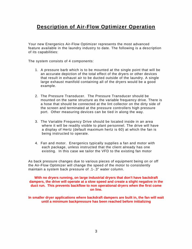
Description of Air-Flow Optimizer Operation
Your new Energenics Air-Flow Optimizer represents the most advanced feature available in the laundry industry to date. The following is a description of its capabilities:
The system consists of 4 components:
1. A pressure barb which is to be mounted at the single point that will be an accurate depiction of the total effect of the dryers or other devices that result in exhaust air to be ducted outside of the laundry. A single large exhaust manifold containing all of the dryers would be a good example.
2. The Pressure Transducer. The Pressure Transducer should be mounted on the same structure as the variable frequency drive. There is a hose that should be connected at the lint collector on the dirty side of the screen and terminated at the pressure controllers high pressure port. Other measuring devices can be tied in along the way.
3. The Variable Frequency Drive should be located inside in an area where it will be readily visible to plant personnel. The drive will have a display of Hertz (default maximum hertz is 60) at which the fan is being instructed to operate.
4. Fan and motor. Energenics typically supplies a fan and motor with each package, unless instructed that the client already has one existing. In this case we tailor the VFD to the existing fan motor
As back pressure changes due to various pieces of equipment being on or off the Air-Flow Optimizer will change the speed of the motor to consistently maintain a system back pressure of .1-.3” water column.
With no dryers running, on large industrial dryers that don’t have backdraft dampers, the drive will operate at a slow speed and create a slight negative in the duct run. This prevents backflow to non operational dryers when the first come
on line.
In smaller dryer applications where backdraft dampers are built in, the fan will wait until a minimum backpressure has been reached before initializing
4
Important Installation Considerations
When mounting the variable frequency drive and the Energenics pressure control attention must be paid to with respect to the location. It is imperative that the system be mounted in a dry relatively clean environment. If mounted outdoors, a motor cover is required to keep direct moisture from entering the motor.
The system should receive its source of voltage from a clean dedicated circuit. As with all solid state components they are not impervious to spikes and surges.
The system should be mounted in a visually conspicuous area that can be observed by plant personnel. The system will display error codes if necessary and will automatically attempt to reset on its own. In the event it does not reset it is very important for an operator to know if there is a problem.

5
Energenics FAQ for Hitachi WJ-200 Drive
1) My drive is always on, even with dryers not running. Why?
Hitachi inverters allows us to run values in the slight negative, further reducing backpressure and also removing condensate from the dryer cylinders while not in operation. In northern climates this is especially useful when outside temperatures are low and nighttime inactivity can result in the cold air returning down the duct into the dryer baskets. This cooling of air produces water and the potential for a delayed startup the following morning.
2) If I don’t want the inverter to run all night, what can I do?
Adjust parameter F001 to 55.00, this will change the set point to a slight positive. To get to parameter F001 press the ESC key until F001 appears, then press SET.
6
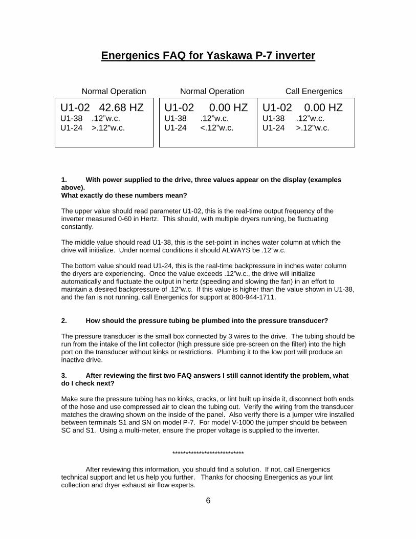
Energenics FAQ for Yaskawa P-7 inverter Normal Operation Normal Operation Call Energenics
1. With power supplied to the drive, three values appear on the display (examples above). What exactly do these numbers mean? The upper value should read parameter U1-02, this is the real-time output frequency of the inverter measured 0-60 in Hertz. This should, with multiple dryers running, be fluctuating constantly. The middle value should read U1-38, this is the set-point in inches water column at which the drive will initialize. Under normal conditions it should ALWAYS be .12”w.c. The bottom value should read U1-24, this is the real-time backpressure in inches water column the dryers are experiencing. Once the value exceeds .12”w.c., the drive will initialize automatically and fluctuate the output in hertz (speeding and slowing the fan) in an effort to maintain a desired backpressure of .12”w.c. If this value is higher than the value shown in U1-38, and the fan is not running, call Energenics for support at 800-944-1711. 2. How should the pressure tubing be plumbed into the pressure transducer? The pressure transducer is the small box connected by 3 wires to the drive. The tubing should be run from the intake of the lint collector (high pressure side pre-screen on the filter) into the high port on the transducer without kinks or restrictions. Plumbing it to the low port will produce an inactive drive. 3. After reviewing the first two FAQ answers I still cannot identify the problem, what do I check next? Make sure the pressure tubing has no kinks, cracks, or lint built up inside it, disconnect both ends of the hose and use compressed air to clean the tubing out. Verify the wiring from the transducer matches the drawing shown on the inside of the panel. Also verify there is a jumper wire installed between terminals S1 and SN on model P-7. For model V-1000 the jumper should be between SC and S1. Using a multi-meter, ensure the proper voltage is supplied to the inverter.
***************************
After reviewing this information, you should find a solution. If not, call Energenics technical support and let us help you further. Thanks for choosing Energenics as your lint collection and dryer exhaust air flow experts.
U1-02 42.68 HZ U1-38 .12”w.c. U1-24 >.12”w.c.
U1-02 0.00 HZ U1-38 .12”w.c. U1-24 <.12”w.c.
U1-02 0.00 HZ U1-38 .12”w.c. U1-24 >.12”w.c.

7

8

9
10

11
12
13

14