INSTALLATION & OPERATION MANUAL FIREPLACE …€¦ · INSTALLATION & OPERATION MANUAL FIREPLACE GAS...
7
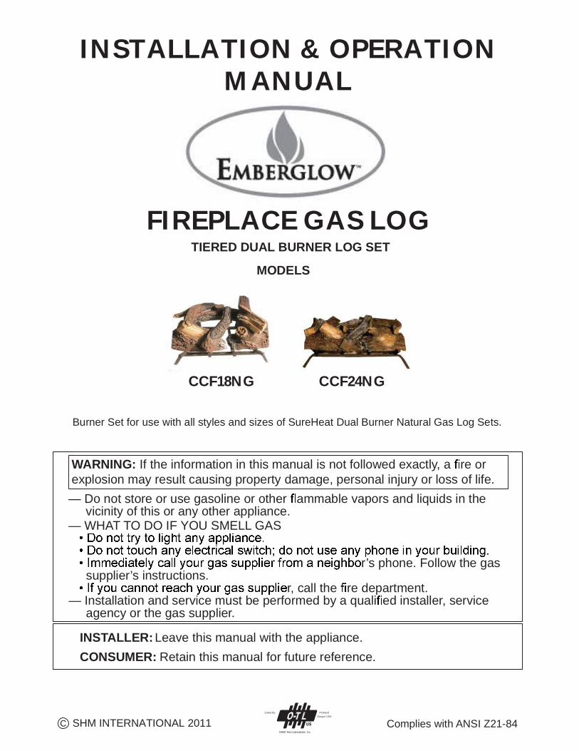
INSTALLATION & OPERATION MANUAL FIREPLACE GAS LOG Burner Set for use with all styles and sizes of SureHeat Dual Burner Natural Gas Log Sets. Complies with ANSI Z21-84 INSTALLER: Leave this manual with the appliance. CONSUMER: Retain this manual for future reference. — Do not store or use gasoline or other ammable vapors and liquids in the vicinity of this or any other appliance. — WHAT TO DO IF YOU SMELL GAS r’s phone. Follow the gas supplier’s instructions. r, call the re department. — Installation and service must be performed by a quali ed installer, service agency or the gas supplier. WARNING: If the information in this manual is not followed exactly, a re or explosion may result causing property damage, personal injury or loss of life. Listed By OMNI-Test Laboratores, Inc. Portland Oregon USA C SHM INTERNATIONAL 2011 TIERED DUAL BURNER LOG SET CCF18NG CCF24NG MODELS
Transcript of INSTALLATION & OPERATION MANUAL FIREPLACE …€¦ · INSTALLATION & OPERATION MANUAL FIREPLACE GAS...
INSTALLATION & OPERATION MANUAL
FIREPLACE GAS LOG
Burner Set for use with all styles and sizes of SureHeat Dual Burner Natural Gas Log Sets.
Complies with ANSI Z21-84
INSTALLER: Leave this manual with the appliance.CONSUMER: Retain this manual for future reference.
— Do not store or use gasoline or other ammable vapors and liquids in the vicinity of this or any other appliance.— WHAT TO DO IF YOU SMELL GAS
r’s phone. Follow the gas supplier’s instructions.
r, call the re department.— Installation and service must be performed by a quali ed installer, service agency or the gas supplier.
WARNING: If the information in this manual is not followed exactly, a re or explosion may result causing property damage, personal injury or loss of life.
Listed By
OMNI-Test Laboratores, Inc.
PortlandOregon USA
C SHM INTERNATIONAL 2011
TIERED DUAL BURNER LOG SET
CCF18NG CCF24NG
MODELS
3
This gas log set is only to be installed and burned in a fully vented fireplace with a fully functional damper and chimney that is free of any obstructions. The fireplace must be constructed of non- combustible materials and approved to burn wood.
To operate this gas log set, the fireplace damper must be fully opened and locked.
The smallest or minimum dimension of the chimney flue must be 8 inches in diameter. Do not use an Energy efficient Gas Log Set if it is smaller than 8 inches. Do not use an Energy Efficient Gas Log Set if fumes from the burner emerge into the room when the damper is fully open. This indicates that there is not adequate draft for this log set and it must not be used until the fireplace draft is corrected.
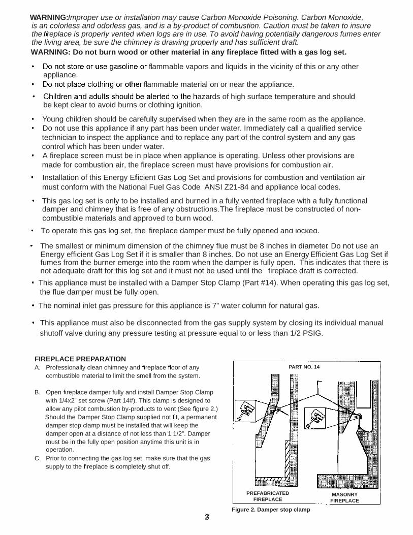
This appliance must be installed with a Damper Stop Clamp (Part #14). When operating this gas log set, the flue damper must be fully open.
The nominal inlet gas pressure for this appliance is 7” water column for natural gas.
This appliance must also be disconnected from the gas supply system by closing its individual manual shutoff valve during any pressure testing at pressure equal to or less than 1/2 PSIG.
3
Installation of this Energy Ef ficient Gas Log Set and provisions for combustion and ventilation air must conform with the National Fuel Gas Code ANSI Z21-84 and appliance local codes.
WARNING:Improper use or installation may cause Carbon Monoxide Poisoning. Carbon Monoxide, is an colorless and odorless gas, and is a by-product of combustion. Caution must be taken to insure the replace is properly vented when logs are in use. To avoid having potentially dangerous fumes enter the living area, be sure the chimney is drawing properly and has sufficient draft.
flammable vapors and liquids in the vicinity of this or any other appliance.
flammable material on or near the appliance. azards of high surface temperature and should
be kept clear to avoid burns or clothing ignition.
Young children should be carefully supervised when they are in the same room as the appliance. Do not use this appliance if any part has been under water. Immediately call a qualified service
technician to inspect the appliance and to replace any part of the control system and any gas control which has been under water. A fireplace screen must be in place when appliance is operating. Unless other provisions are
made for combustion air, the fireplace screen must have provisions for combustion air.
WARNING: Do not burn wood or other material in any fireplace fitted with a gas log set.
FIREPLACE PREPARATIONA. Professionally clean chimney and replace oor of any
combustible material to limit the smell from the system.
B. Open replace damper fully and install Damper Stop Clamp with 1/4x2” set screw (Part 14#). This clamp is designed to allow any pilot combustion by-products to vent (See gure 2.)
Should the Damper Stop Clamp supplied not t, a permanent damper stop clamp must be installed that will keep the damper open at a distance of not less than 1 1/2”. Damper must be in the fully open position anytime this unit is in operation.
C. Prior to connecting the gas log set, make sure that the gas supply to the replace is completely shut off.
PREFABRICATEDFIREPLACE
MASONRYFIREPLACE
Figure 2. Damper stop clamp
PART NO. 14
4
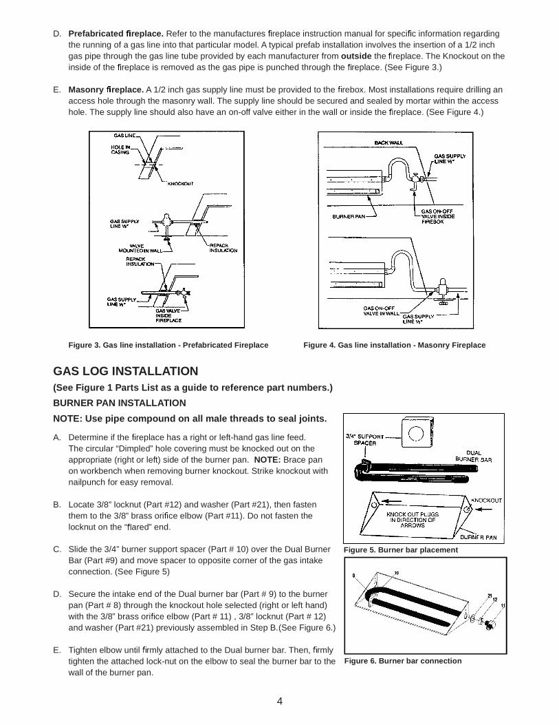
D. Prefabricated replace. Refer to the manufactures replace instruction manual for speci c information regarding the running of a gas line into that particular model. A typical prefab installation involves the insertion of a 1/2 inch gas pipe through the gas line tube provided by each manufacturer from outside the replace. The Knockout on the inside of the replace is removed as the gas pipe is punched through the replace. (See Figure 3.)
E. Masonry replace. A 1/2 inch gas supply line must be provided to the rebox. Most installations require drilling an access hole through the masonry wall. The supply line should be secured and sealed by mortar within the access hole. The supply line should also have an on-off valve either in the wall or inside the replace. (See Figure 4.)
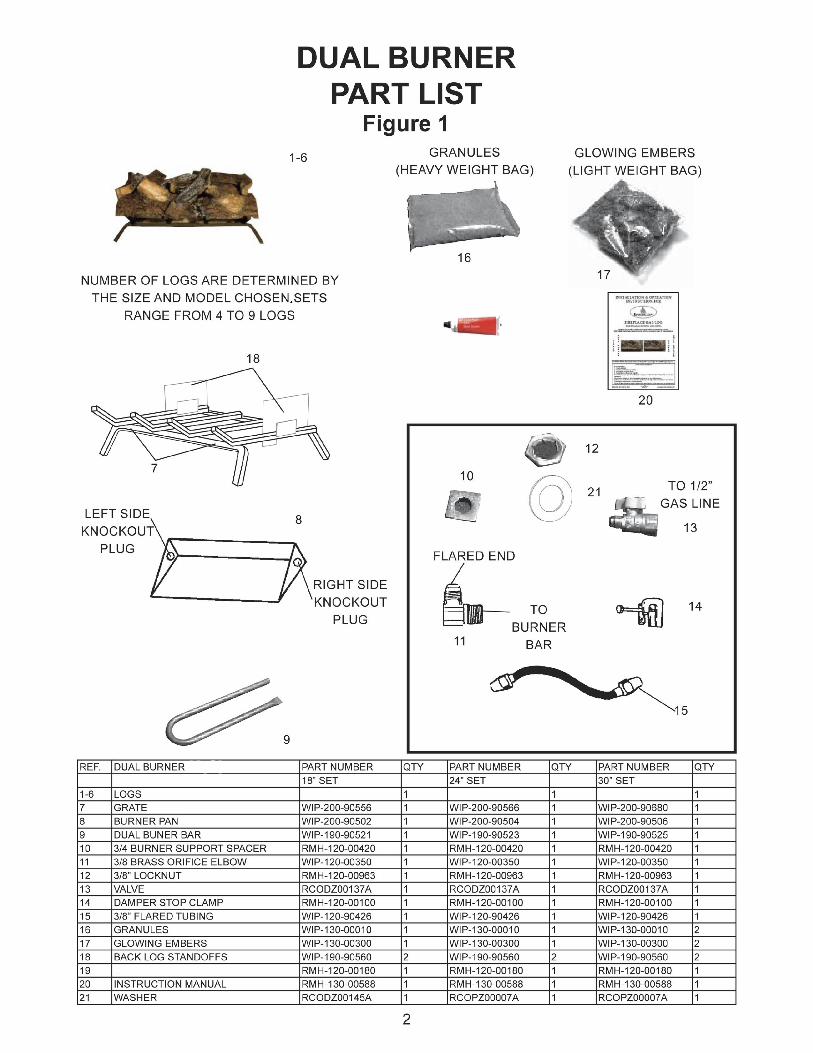
GAS LOG INSTALLATION(See Figure 1 Parts List as a guide to reference part numbers.)BURNER PAN INSTALLATIONNOTE: Use pipe compound on all male threads to seal joints.
A. Determine if the replace has a right or left-hand gas line feed. The circular “Dimpled” hole covering must be knocked out on the appropriate (right or left) side of the burner pan. NOTE: Brace pan on workbench when removing burner knockout. Strike knockout with nailpunch for easy removal.
B. Locate 3/8” locknut (Part #12) and washer (Part #21), then fasten them to the 3/8” brass ori ce elbow (Part #11). Do not fasten the locknut on the “ ared” end.
C. Slide the 3/4” burner support spacer (Part # 10) over the Dual Burner Bar (Part #9) and move spacer to opposite corner of the gas intake connection. (See Figure 5)
D. Secure the intake end of the Dual burner bar (Part # 9) to the burner pan (Part # 8) through the knockout hole selected (right or left hand) with the 3/8” brass ori ce elbow (Part # 11) , 3/8” locknut (Part # 12) and washer (Part #21) previously assembled in Step B.(See Figure 6.)
E. Tighten elbow until rmly attached to the Dual burner bar. Then, rmly tighten the attached lock-nut on the elbow to seal the burner bar to the wall of the burner pan.
Figure 3. Gas line installation - Prefabricated Fireplace Figure 4. Gas line installation - Masonry Fireplace
Figure 5. Burner bar placement
Figure 6. Burner bar connection
5
CONNECTING GAS SUPPLY TO BURNER ASSEMBLY(If a Safety Pilot Kit is to be used, please refer to separate installation instructions.) These instructions refer to Natural Gas applications installed without a Safety Pilot Kit. LP/NG Safety Pilot Kit available at your local store.
A. Place burner pan assembly in the center of the replace.
B. Attach 3/8” Flare X 1/2” NPT gas valve (Part #13) to the 1/2 inch gas supply stub already in fireplace. Be certain connections are tight and use pipe compound on all male NPT (pipe) threads to seal joints
C. Attach 3/8” flared tubing (Part #15) to burner pan assembly. Attach opposite end to gas supply line by carefully bending the ared tubing as needed to make the connection. Avoid kinking the flared tubing while bending. If tubing must be cut, use a tube cutter. Flare the cut end of the tube with a aring tool.NOTE: A good method of bending the tube is to ll it with sand, bending the tube as needed to make the connection. This method will eliminate kinking in the line. Once the tube is in the desired con guration for hookup, be sure to empty the tube completely of any sand before tube is connected to the gas supply line and the burner.
D. Be certain all connections are tight. Only use pipe compound on all male NPT (pipe) threads. Test all connections with a soapy water solution with the gas supply turned on. If bubbles appear on any connection, retighten and retest. Once it is determined there are no leaks whatsoever, turn off gas supply and move to next assembly step.
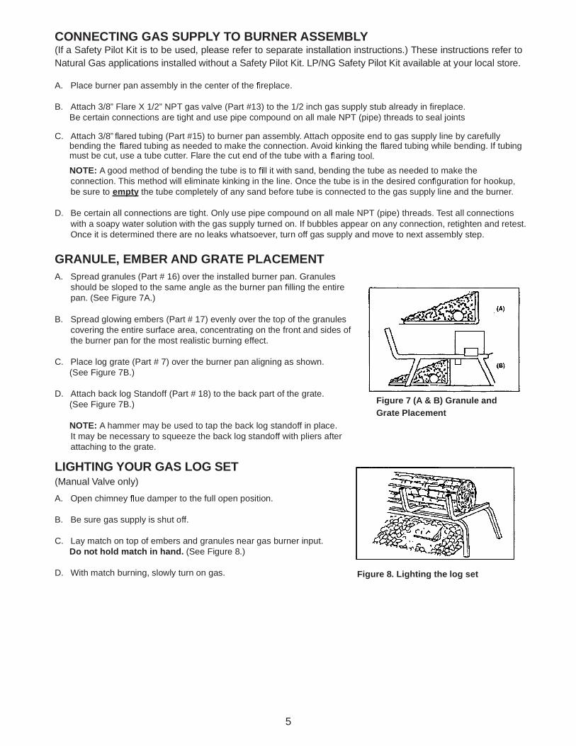
GRANULE, EMBER AND GRATE PLACEMENTA. Spread granules (Part # 16) over the installed burner pan. Granules
should be sloped to the same angle as the burner pan lling the entire pan. (See Figure 7A.)
B. Spread glowing embers (Part # 17) evenly over the top of the granules covering the entire surface area, concentrating on the front and sides of the burner pan for the most realistic burning effect.
C. Place log grate (Part # 7) over the burner pan aligning as shown. (See Figure 7B.)
D. Attach back log Standoff (Part # 18) to the back part of the grate. (See Figure 7B.)
NOTE: A hammer may be used to tap the back log standoff in place. It may be necessary to squeeze the back log standoff with pliers after attaching to the grate.
LIGHTING YOUR GAS LOG SET(Manual Valve only)
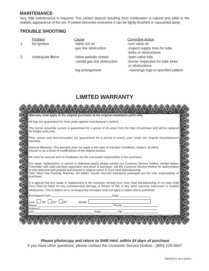
A. Open chimney ue damper to the full open position.
B. Be sure gas supply is shut off.
C. Lay match on top of embers and granules near gas burner input. Do not hold match in hand. (See Figure 8.)
D. With match burning, slowly turn on gas.
Figure 7 (A & B) Granule and Grate Placement
Figure 8. Lighting the log set

Proper Log Placement For Vented Gas Logs
CCF18NG Canyon Campfi re 1
CCF24NG Canyon Campfi re
If you have any questions, please call (800) 229-5647 for customer service.
2
3 4
1 2
3 4
MAINTENANCEVery little maintenance is required. The carbon deposit resulting from combustion is natural and adds to the realistic appearance of the set. If carbon becomes excessive it can be lightly brushed or vacuumed away.
TROUBLE SHOOTINGProblem Cause Corrective Action
1. No Ignition -Valve not on -turn valve on-gas line obstruction -inspect supply lines for tube
kinks or obstructions2. Inadequate ame -Valve partially closed -open valve fully
- partial gas line obstruction -burner inspection for tube kinks or obstructions
-log arrangement -rearrange logs to specified pattern
LIMITED WARRANTY
Warranty shall apply to the original purchaser at the original installation point only.
All logs are guaranteed for three years against manufacturer’s defects.
The burner assembly system is guaranteed for a period of (3) years from the date of purchase and will be replaced for freight costs only.
Pilot, valves and thermocouples are guaranteed for a period of one(1) year under the original manufacturers warranty.
General Warranty: This warranty does not apply in the case of improper installation, neglect, accident. misuse or as a result of modi cations of the original product.
All costs for removal and re-installation are the expressed responsibility of the purchaser.
For repair, replacement, or service to defective part(s) please contact our Customer Service Hotline, number below. Thereafter with valid warranty registration and proof of purchase, call the Customer Service Hotline for authorization to ship defective part prepaid and insured in original carton to Sure Heat Manufacturing.1861 West Oak Partway, Marietta, GA 30062. Goods returned improperly packaged are the sole responsibility of purchaser.
It is agreed that any repair or replacement is the exclusive remedy from Sure Heat Manufacturing. In no case shall Sure Heat be liable for any consequential damage or breach of this or any other warranty expressed or implied whatsoever. This limitation as to consequential damages shall not apply in states where prohibited.
Purchased From: Date:
Size: 18" 24" 30" Model:Name: Phone:Address:City: State: Zip:
Please photocopy and return to SHM Intnl. within 14 days of purchaseIf you have other questions, please contact the Customer Service Hotline - (800) 229-5647
R84026CC Re v.5/2012