Installation, Operation & Maintenance Manual - Yenen Installation, Operation & Maintenance Manual...
28
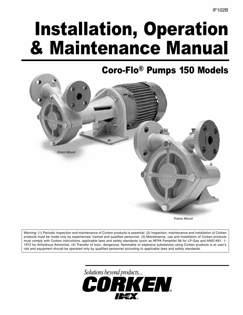
IF102B Installation, Operation & Maintenance Manual Coro-Flo ® Pumps 150 Models Direct Mount Warning: (1) Periodic inspection and maintenance of Corken products is essential. (2) Inspection, maintenance and installation of Corken products must be made only by experienced, trained and qualified personnel. (3) Maintenance, use and installation of Corken products must comply with Corken instructions, applicable laws and safety standards (such as NFPA Pamphlet 58 for LP-Gas and ANSI K61. 1- 1972 for Anhydrous Ammonia). (4) Transfer of toxic, dangerous, flammable or explosive substances using Corken products is at user’s risk and equipment should be operated only by qualified personnel according to applicable laws and safety standards. Frame Mount
Transcript of Installation, Operation & Maintenance Manual - Yenen Installation, Operation & Maintenance Manual...
IF102B
Installation, Operation& Maintenance Manual
Coro-Flo® Pumps 150 Models
Direct Mount
Warning: (1) Periodic inspection and maintenance of Corken products is essential. (2) Inspection, maintenance and installation of Corkenproducts must be made only by experienced, trained and qualified personnel. (3) Maintenance, use and installation of Corken productsmust comply with Corken instructions, applicable laws and safety standards (such as NFPA Pamphlet 58 for LP-Gas and ANSI K61. 1-1972 for Anhydrous Ammonia). (4) Transfer of toxic, dangerous, flammable or explosive substances using Corken products is at user’srisk and equipment should be operated only by qualified personnel according to applicable laws and safety standards.
Frame Mount
The Model and Serial Numbers are shown on the nameplate of the unit. Record this information forfuture reference.
Model No.
Serial No.
Date Purchased
Date Installed
Purchased From
Installed By
WARNINGInstall, use and maintain this equipment according to Corken’s instructions and all applicable federal, state,local laws and codes. Periodic inspection and maintenance is essential.
CONTACTING THE FACTORYBefore you contact the factory, note the Model Number and Serial Number of your pump. The Serial Numberdirects us to a file containing all information on material specifications and test data applying to your specific pump.When ordering parts, the Corken Service Manual or Instruction Book should be consulted for the proper PartNumbers. ALWAYS INCLUDE THE MODEL NUMBER AND SERIAL NUMBER WHEN ORDERING PARTS.
CORKEN ONE YEAR LIMITED WARRANTYCorken, Inc. warrants that its products will be free from defects in material and workmanship for a period of12 months following date of purchase from Corken. Corken products which fail within the warranty perioddue to defects in material or workmanship will be repaired or replaced at Corken’s option, when returnedfreight prepaid to CORKEN, INC., 3805 N.W. 36th Street, Oklahoma City, Oklahoma 73112.
Parts subject to wear or abuse, such as mechanical seals, blades, piston rings, packing and other partsshowing signs of abuse are not covered by this limited warranty. Also, equipment, parts and accessories notmanufactured by Corken but furnished with Corken products are not covered by this limited warranty andpurchaser must look to the original manufacturer’s warranty, if any. This limited warranty is void if the Corkenproduct has been altered or repaired without the consent of Corken.
All implied warranties, including any implied warranty of merchantability or fitness for a particular purpose,are expressly negated to the extent permitted by law and shall in no event extend beyond the expressedwarranty period.
CORKEN DISCLAIMS ANY LIABILITY FOR CONSEQUENTIAL DAMAGES DUE TO BREACH OF ANYWRITTEN OR IMPLIED WARRANTY ON CORKEN PRODUCTS. Transfer of toxic, dangerous, flammableor explosive substances using Corken products is at the user’s risk. Such substances should be handled byexperienced, trained personnel in compliance with governmental and industrial safety standards.
IMPORTANT NOTES RELATING TO THE EUROPEAN UNION (EU) MACHINERY DIRECTIVEPumps delivered without electric motors are not considered as machines in the EU Machinery Directive.These pumps will be delivered with a Declaration of Incorporation. The fabricator of the machinery mustassure and declare full compliance with this Directive before the machine in which the pump will beincorporated, or of which it is a part, is put into service.
TABLE OF CONTENTS
PRINCIPLES OF THE CORKEN CORO-FLO® PUMP . . . . . . . . . . . . . . . . . . . . . . . . . . . . . . . . . . . . . . . . . . . Page 4
EXCLUSIVE FEATURES OF YOUR CORKEN CORO-FLO® PUMP. . . . . . . . . . . . . . . . . . . . . . . . . . . . . . . . Page 4
INSTALLATION OF YOUR CORKEN CORO-FLO® PUMP . . . . . . . . . . . . . . . . . . . . . . . . . . . . . . . . . . . . . . . Page 4
Inlet piping should include the following . . . . . . . . . . . . . . . . . . . . . . . . . . . . . . . . . . . . . . . . . . . . . . . . Page 5
Outlet piping should include the following. . . . . . . . . . . . . . . . . . . . . . . . . . . . . . . . . . . . . . . . . . . . . . . Page 5
Bypass system must include the following . . . . . . . . . . . . . . . . . . . . . . . . . . . . . . . . . . . . . . . . . . . . . . Page 5
Design criteria for underground tank applications . . . . . . . . . . . . . . . . . . . . . . . . . . . . . . . . . . . . . . . . Page 5
Pump foundation for frame mounted models . . . . . . . . . . . . . . . . . . . . . . . . . . . . . . . . . . . . . . . . . . . . Page 6
Level base . . . . . . . . . . . . . . . . . . . . . . . . . . . . . . . . . . . . . . . . . . . . . . . . . . . . . . . . . . . . . . . . . . . . . . . . . Page 6
Coupling alignment for frame mounted models . . . . . . . . . . . . . . . . . . . . . . . . . . . . . . . . . . . . . . . . . . Page 6
Driver installation . . . . . . . . . . . . . . . . . . . . . . . . . . . . . . . . . . . . . . . . . . . . . . . . . . . . . . . . . . . . . . . . . . . Page 6
Wire sizing chart . . . . . . . . . . . . . . . . . . . . . . . . . . . . . . . . . . . . . . . . . . . . . . . . . . . . . . . . . . . . . . . . . . . . Page 7
OPERATION OF YOUR CORO-FLO® PUMP . . . . . . . . . . . . . . . . . . . . . . . . . . . . . . . . . . . . . . . . . . . . . . . . . . Page 7
FILLING NEW CYLINDERS AND TANKS . . . . . . . . . . . . . . . . . . . . . . . . . . . . . . . . . . . . . . . . . . . . . . . . . . . . Page 8
PREVENTATIVE MAINTENANCE PROGRAM. . . . . . . . . . . . . . . . . . . . . . . . . . . . . . . . . . . . . . . . . . . . . . . . . Page 8
REPAIR AND SERVICE ON YOUR CORO-FLO® PUMP . . . . . . . . . . . . . . . . . . . . . . . . . . . . . . . . . . . . . . . . . Page 9
SEAL REPLACEMENT INSTRUCTIONS . . . . . . . . . . . . . . . . . . . . . . . . . . . . . . . . . . . . . . . . . . . . . . . . . . . . Page 10
PARTS DETAILS - FRAME MOUNT (ANSI (FF) AND DIN (FD) FLANGE). . . . . . . . . . . . . . . . . . . . . . . . . . Page 12
PARTS DETAILS - DIRECT MOUNT (ANSI (DLF) AND DIN (DLD) FLANGE) . . . . . . . . . . . . . . . . . . . . . . Page 13
UNDERGROUND TANK APPLICATION PIPING DIAGRAM . . . . . . . . . . . . . . . . . . . . . . . . . . . . . . . . . . . . . Page 14
UNDERGROUND TANK WITH MANIFOLD FOR SUBMERSIBLE PUMP . . . . . . . . . . . . . . . . . . . . . . . . . . Page 16
ABOVE GROUND INSTALLATION TIPS . . . . . . . . . . . . . . . . . . . . . . . . . . . . . . . . . . . . . . . . . . . . . . . . . . . . Page 18
APPENDICIES
APPENDIX A: MODEL NUMBER AND MOUNTING IDENTIFICATION CODES . . . . . . . . . . . . . . . . . . . . . Page 21
APPENDIX B: MATERIAL AND OPERATING SPECIFICATIONS. . . . . . . . . . . . . . . . . . . . . . . . . . . . . . . . . Page 22
APPENDIX C: PERFORMANCE CURVES. . . . . . . . . . . . . . . . . . . . . . . . . . . . . . . . . . . . . . . . . . . . . . . . . . . Page 23
APPENDIX D: OUTLINE DIMENSIONS FOR FRAME MOUNT . . . . . . . . . . . . . . . . . . . . . . . . . . . . . . . . . . Page 24
APPENDIX E: OUTLINE DIMENSIONS FOR DIRECT MOUNT . . . . . . . . . . . . . . . . . . . . . . . . . . . . . . . . . . Page 25
APPENDIX F: TROUBLESHOOTING GUIDE . . . . . . . . . . . . . . . . . . . . . . . . . . . . . . . . . . . . . . . . . . . . . . . . Page 26
APPENDIX G: EXTENDED STORAGE PROCEDURES . . . . . . . . . . . . . . . . . . . . . . . . . . . . . . . . . . . . . . . . Page 27

4 CORO-FLO® PUMPS - 150 MODELS
PRINCIPLES OF THE CORKEN CORO-FLO® PUMPThe Corken Coro-Flo® pump is a special type of pumpknown as a turbine or regenerative pump. The liquidflows into the inlet nozzle and into the passageway oneach side of an impeller (the rotating element) and isrecirculated constantly between the vanes or teeth ofthe impeller and this passageway as the impellerrotates. The fluid makes a complete revolution in thepump case and is diverted out the outlet nozzle. Thehorsepower required to drive the pump increases asthe differential pressure increases, but the capacitydecreases at the same time. Differential pressure isthe difference between the pressure at the inlet of thepump and at the outlet of the pump.
The impeller is the only moving part and has nocontact with the casing. Consequently, practically nowear occurs to the impeller, even when pumpingvolatile liquids such as LP-gas or ammonia whichhave little lubricating qualities.
EXCLUSIVE FEATURES OF YOURCORKEN CORO-FLO® PUMPThe pumping of volatile liquids is one of the most difficultof all pumping applications. Unlike other pumpingapplications, more attention must be given to the design,manufacture, installation and operation of the pump.
In addition to being a pump type especially suited forhandling volatile liquids, your CORO-FLO® pump hasa number of features which help to make it moreeasily operated and maintained.
The CORO-FLO® pumps of this series are manufacturedto be directly connected to an electric motor (directmount) or with their own frame for connection by meansof a flexible coupling (frame mount).
UNDERWRITERS' LABORATORIES, INC. havetested and inspected the CORO-FLO® pumps of thisseries and have listed them for use in the handling ofLP-gas and ammonia fluids. The nameplate on thepump includes the UL registration.
DUCTILE IRON has been used in the manufactureof this pump for parts under pressure.
THE IMPELLER floats on a shaft and may be replacedeasily without disturbing the piping or driver by simplyremoving the cover. No special tools are needed.
THE MECHANICAL SEAL ASSEMBLY may bereplaced easily by removing the cover and impellerwithout disturbing the piping or driver. No specialtools are needed.
THE PUMP NOZZLES MAY BE ROTATED into fourdifferent positions, 180 degrees apart, if desired.
PRESSURE GAUGE CONNECTIONS, 1/4" FNPT, areprovided on the inlet and outlet nozzles.
INSTALLATION OF YOUR CORKEN CORO-FLO® PUMPTHE INSTALLATION OF A CORO-FLO® pump issimple. However, in order for the pump to deliveroptimum performance, the principles discussed inthis book should be followed. The piping details arefurnished to illustrate methods proved by hundredsof installations. Your own needs may require slightvariations, but every effort should be made to followthe recommendations identified in this manual.
For the transfer of flammable liquids like LPG, the pumpassembly must be installed according to the applicablelocal safety and health regulations. The installer and/orthe user must take into account the following:
• Potential risk due to local conditions regarding theinstallation and operation (e.g. poor ventilationand additional risks due to other elements in thevicinity, etc.).
• Qualification of the personnel.• Type of liquid being transferred.• Specific safety measures to be applied (e.g. gas
detection, automatic shut-off valves, personalprotection equipment etc.).
For more detailed piping arrangements, refer topages 14 - 20. For outline dimensional drawings,refer to Appendix D & E (pages 24-25).
The following table shows the weight of the bare pumpfor each model. For handling a bare pump, liftingslings should be placed around the inlet and outletflange neck of the pump. Web slings are preferredover metal slings to minimize damage to the paint.
Shipping Weight Model lb kg
Frame Mount 63 28.6Direct Mount 75 34.0

CORO-FLO® PUMPS - 150 MODELS 5
IF IT IS DESIRABLE TO ROTATE THE NOZZLES ofthe pump, remove the four cap screws on the pumpcase and rotate pump casing to desired position. Becareful to do this without moving the case away fromthe mounting frame; otherwise, the mechanical sealmay be damaged.
NO PUMP CAN DISCHARGE MORE LIQUID THAN ITRECEIVES, so the location and the inlet piping must begiven careful attention. If the inlet piping is inadequate tosupply the demand of the pump, you may expect trouble!The inlet line size should be the same size as the pumpsuction or next size larger. Pressure loss between thestorage tank and the pump should be minimized.
THE PUMP SHOULD BE LOCATED AS CLOSE TOTHE STORAGE TANK as possible. The completeinlet line, including the vertical line from the tank,should not exceed 12 feet (3.6 m) in length. Thebottom of the tank should be at least two feet (0.6 m)above the pump inlet nozzle, and four feet (1.2 m)should be considered standard.
The inlet should include the following:1. The tank excess flow valve (EFV) should have a flow
rate of 1-1/2 to 2 times the capacity of the pump. Donot use an EFV without knowing its flow capacity.
2. Pressure gauge at pump suction nozzle.
3. The tank shutoff valve should be a full port ballvalve or an internal valve.
4. A strainer of the "Y" type, with a 20 mesh screen,should be on the inlet line of the pump.
5. A flexible connection should be used on the pumpinlet or outlet to accomodate piping strains.
6. An eccentric swage should be used at the pumpinlet nozzle to change line size (flat side up).
7. The inlet line must be level or slope downward tothe pump.
The outlet piping should include thefollowing:
1. A pressure gauge should be installed in theopening provided on the outlet nozzle or in theoutlet piping near the pump. This pressure gaugewill tell you the complete story of the operationinside your pump. Be sure you have one installed.
2. A hydrostatic relief valve is required to be installedin the outlet piping.
3. If the outlet piping exceeds 50 feet (15.2 m) inlength, a check valve should be installed near thepump outlet.
The bypass system must include thefollowing:1. The pump bypass system must be installed. Without
this system, the pump has little chance of performing.
2. A CORKEN B166 BYPASS VALVE (a special valveto vent the pump of vapors and to act as adifferential relief valve) is ideal.
3. The bypass line should rise uninterrupted to anopening in the vapor section of the storage tank.The tank fitting should be either an excess flowvalve or a vapor return valve; it should never be afiller valve or a back check valve.
4. To meet Underwriters’ Laboratories (UL)specifications, an external bypass valve must beconnected in the piping between the pumpdischarge nozzle and the supply tank for pumprecirculation. When bypassing the full output of thepump, the external bypass valve must limit thedifferential pressure to 125 pounds per square inch.
DESIGN CRITERIA FORUNDERGROUND TANKAPPLICATIONS:
• Minimize suction frictional losses:
- Locate pump as close as possible to the tank’sliquid outlet connection.
- Eliminate strainer, since the tank itself acts as asump to collect foreign materials.
- Use full-port ball valves, or low restrictive valves.
- Use 2-inch (51 millimeter) pipe.
• Minimize the net static suction lift, to 14 feet(4.3 m) maximum.
• Use vapor eliminator valves.
• Use back-pressure check valves downstreamthe pump.
• Limit the capacity of the pump to a maximum of1.5% of the tank’s capacity. For example, with a1,000-gallon (3,785 liter) tank, limit the capacityof the pump to 15 gallons per minute (56.8 litersper minute).

Pump foundation for frame mounted modelsThe pump assembly must be securely attached to aconcrete foundation using all the available holes in thepump assembly footing. The total weight of theconcrete foundation should be approximately twicethe weight of the pump assembly. The foundation mustbe level and deep enough to get below the groundfrost line in the location. There are many ways toconstruct a foundation, and the example in figure 1 isonly a suggestion.
Level baseAfter the concrete has set, check the pump base forlevel. Drive metal shims under the base near theanchor bolts as below. Tighten anchor bolts andrecheck the base for level (see figure 2).
Coupling alignment for frame mountmodelsThe coupling must be properly aligned to give quiet,long-life service to the pump and driver. The pumpand driver shafts are carefully aligned at the factorybut should always be checked after the pump isinstalled and before the initial operation.
Place a straight edge across coupling halves, topand side; both positions must line up to be correct.
If misalignment exists, adjust the shims between thepump base and the foundation until exact alignmentis accomplished (see figure 3).
Driver installation
A qualified electrician, in accordance with all the localstandards and regulations, must undertake theelectrical installation. The wire size chart on page 7,figure 4 indicates the minimum standards for wire sizes.
Improper motor wiring may cause you to experienceexpensive motor difficulties from low voltage. If yoususpect you have low voltage, call your powercompany. Wiring your motor for the voltage you haveavailable is important. Be sure your motor isconnected to the proper voltage. Connecting toimproper voltage will completely destroy your motor.
With explosion-proof motor applications in humidclimates, the normal breathing and alternatingtemperatures of the motor (warm during operation andcold when stopped) will often cause moist air to bedrawn into the motor housing. This moist air willcondense and may eventually add enough free waterto the inside of the motor to cause it to fail. To preventthis, make a practice of running the motor and pump atleast once a week on a dry day for an hour or so (pumpthrough the bypass system). This allows the motor toheat and vaporize the condensed moisture. No motormanufacturer will guarantee an explosion-proof ortotally enclosed motor against damage from moisture.
ENGINE DRIVERS require special consideration;the manufacturer's instructions must be followed.When the Coro-Flo® pump is equipped with anengine from the factory, the engine speed shouldnormally not exceed 3600 rpm. Excessive enginespeed will overload the engine and cause earlyfailure. The engine loses 3% of its power for every1000 feet above sea level, so if your installation is ata higher altitude than normal, consult the factory.
6 CORO-FLO® PUMPS - 150 MODELS
Figure 2
Figure 3
Figure 1

CORO-FLO® PUMPS - 150 MODELS 7
MOTOR
HP MOTOR PHASE VOLTSAPPROX. FULL
LOAD AMPERES
LENGTH OF RUN IN FEET
0-100 TO 200 TO 300
RECOMMENDED WIRE SIZE, AWG
Pump must rotate clockwise when viewed from the motor. If not, switch any two of the three incoming 3 phase lines.
3 1 115 34.0 6 4 2230 17.0 12 8 8
3 230 9.6 12 12 12460 4.8 12 12 12
5 1 115 56.0 4 1 1/0230 28.0 10 6 4
3 230 15.2 12 12 10460 7.6 12 12 12
7-1/2 1 230 40.0 8 6 43 230 22.0 10 10 8
460 11.0 12 12 12
10 3 230 28 8 6 4460 14 12 12 10
15 3 230 42 6 4 4460 21 10 10 8
20 3 230 54 6 6 4460 27 10 10 10
Figure 4WIRE SIZE CHART FOR WIRING ELECTRIC MOTOR1
1 Each country may use a different form of wire size measurement (AWG, SWG, mm2 etc.). The above wiring size chart isbased on the United States National Electrical Code (NEC) guidelines for America Wire Gauge (AWG) sizes. These wire sizesand distances are based on nominal supplied voltages. Additional derating is necessary when the voltage is less than thatshown. Consult your local standards and regulation for specific wiring requirements.
OPERATION OF YOUR CORO-FLO® PUMPIt is absolutely essential that the operator be fullyinformed of the pump’s recommended operationprocedures and safety precautions. See AppendixB & C, pages 22 & 23 for operating specificationsand performance. The operator must be madeaware of the specific risks generated by the producthandled and be familiar with the purpose andfunction of all piping, valves, and instrumentation,etc. of the installation.
The following steps should be performed for theinitial pumping operation:
1. Close shutoff valve on the end of the delivery hose.
2. Open the storage tank bottom shutoff valve.
3. Open the shutoff valve in the pump bypass system.
4. Check the motor for the proper voltage (seeinstructions under driver installation).
5. Record pressure gauge readings on suction of pump.
6. Start the pump and circulate liquid through thebypass system.
7. Adjust the B166 bypass valve by turning theadjusting screw counterclockwise until the pumppressure gauge shows nearly the samepressure it did before you started the pump.Screw the adjusting screw clockwise until thepressure gauge indicates the required pressureor until the pump starts to lose dischargepressure (you will know this by the rapidfluctuating of the pointer), then back theadjusting screw out a turn or two until thepressure gauge again indicates a steadypressure. Lock the lock nut and permit the pumpto circulate liquid for a half hour or more. If themotor overload protection device stops themotor during this period, this indicates thebypass system valve is set too high and shouldbe readjusted by turning the adjusting screw outuntil the motor will run for this period.
When properly installed and operated, Coro-Flo®
pumps do not exceed a 80 dBAnoise level at a distanceof one meter (3.281 ft.) from the surface of the pump.
8 CORO-FLO® PUMPS - 150 MODELS
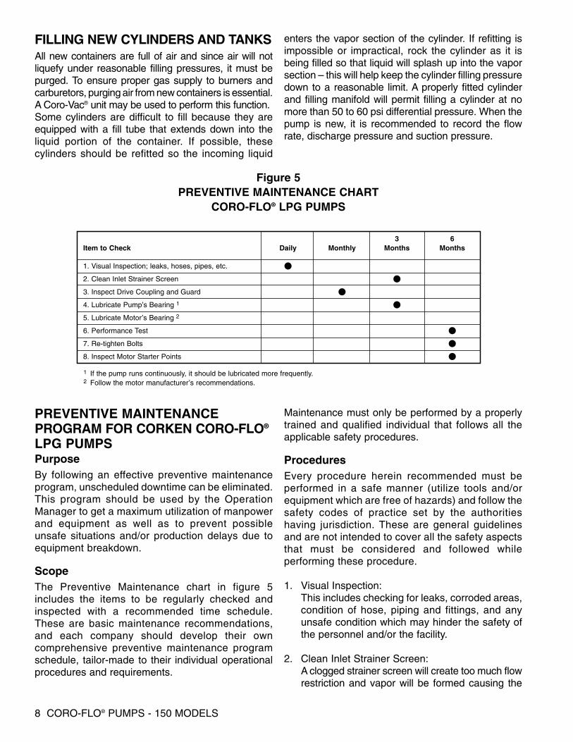
Figure 5PREVENTIVE MAINTENANCE CHART
CORO-FLO® LPG PUMPS
3 6Item to Check Daily Monthly Months Months
1. Visual Inspection; leaks, hoses, pipes, etc. •2. Clean Inlet Strainer Screen •3. Inspect Drive Coupling and Guard •4. Lubricate Pump’s Bearing 1 •5. Lubricate Motor’s Bearing 2
6. Performance Test •7. Re-tighten Bolts •8. Inspect Motor Starter Points •1 If the pump runs continuously, it should be lubricated more frequently.2 Follow the motor manufacturer’s recommendations.
FILLING NEW CYLINDERS AND TANKSAll new containers are full of air and since air will notliquefy under reasonable filling pressures, it must bepurged. To ensure proper gas supply to burners andcarburetors, purging air from new containers is essential.A Coro-Vac® unit may be used to perform this function.Some cylinders are difficult to fill because they areequipped with a fill tube that extends down into theliquid portion of the container. If possible, thesecylinders should be refitted so the incoming liquid
enters the vapor section of the cylinder. If refitting isimpossible or impractical, rock the cylinder as it isbeing filled so that liquid will splash up into the vaporsection – this will help keep the cylinder filling pressuredown to a reasonable limit. A properly fitted cylinderand filling manifold will permit filling a cylinder at nomore than 50 to 60 psi differential pressure. When thepump is new, it is recommended to record the flowrate, discharge pressure and suction pressure.
PREVENTIVE MAINTENANCEPROGRAM FOR CORKEN CORO-FLO®
LPG PUMPSPurposeBy following an effective preventive maintenanceprogram, unscheduled downtime can be eliminated.This program should be used by the OperationManager to get a maximum utilization of manpowerand equipment as well as to prevent possibleunsafe situations and/or production delays due toequipment breakdown.
ScopeThe Preventive Maintenance chart in figure 5includes the items to be regularly checked andinspected with a recommended time schedule.These are basic maintenance recommendations,and each company should develop their owncomprehensive preventive maintenance programschedule, tailor-made to their individual operationalprocedures and requirements.
Maintenance must only be performed by a properlytrained and qualified individual that follows all theapplicable safety procedures.
ProceduresEvery procedure herein recommended must beperformed in a safe manner (utilize tools and/orequipment which are free of hazards) and follow thesafety codes of practice set by the authoritieshaving jurisdiction. These are general guidelinesand are not intended to cover all the safety aspectsthat must be considered and followed whileperforming these procedure.
1. Visual Inspection:This includes checking for leaks, corroded areas,condition of hose, piping and fittings, and anyunsafe condition which may hinder the safety ofthe personnel and/or the facility.
2. Clean Inlet Strainer Screen:A clogged strainer screen will create too much flowrestriction and vapor will be formed causing the
CORO-FLO® PUMPS - 150 MODELS 9
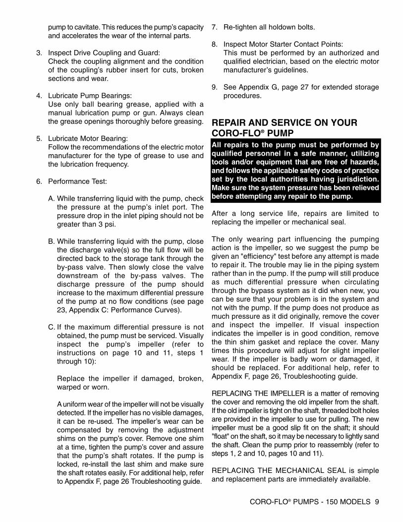
pump to cavitate. This reduces the pump’s capacityand accelerates the wear of the internal parts.
3. Inspect Drive Coupling and Guard:Check the coupling alignment and the conditionof the coupling’s rubber insert for cuts, brokensections and wear.
4. Lubricate Pump Bearings:Use only ball bearing grease, applied with amanual lubrication pump or gun. Always cleanthe grease openings thoroughly before greasing.
5. Lubricate Motor Bearing:Follow the recommendations of the electric motormanufacturer for the type of grease to use andthe lubrication frequency.
6. Performance Test:
A. While transferring liquid with the pump, checkthe pressure at the pump’s inlet port. Thepressure drop in the inlet piping should not begreater than 3 psi.
B. While transferring liquid with the pump, closethe discharge valve(s) so the full flow will bedirected back to the storage tank through theby-pass valve. Then slowly close the valvedownstream of the by-pass valves. Thedischarge pressure of the pump shouldincrease to the maximum differential pressureof the pump at no flow conditions (see page23, Appendix C: Performance Curves).
C. If the maximum differential pressure is notobtained, the pump must be serviced. Visuallyinspect the pump’s impeller (refer toinstructions on page 10 and 11, steps 1through 10):
Replace the impeller if damaged, broken,warped or worn.
A uniform wear of the impeller will not be visuallydetected. If the impeller has no visible damages,it can be re-used. The impeller’s wear can becompensated by removing the adjustmentshims on the pump’s cover. Remove one shimat a time, tighten the pump’s cover and assurethat the pump’s shaft rotates. If the pump islocked, re-install the last shim and make surethe shaft rotates easily. For additional help, referto Appendix F, page 26 Troubleshooting guide.
7. Re-tighten all holdown bolts.
8. Inspect Motor Starter Contact Points:This must be performed by an authorized andqualified electrician, based on the electric motormanufacturer’s guidelines.
9. See Appendix G, page 27 for extended storageprocedures.
REPAIR AND SERVICE ON YOUR CORO-FLO® PUMPAll repairs to the pump must be performed byqualified personnel in a safe manner, utilizingtools and/or equipment that are free of hazards,and follows the applicable safety codes of practiceset by the local authorities having jurisdiction.Make sure the system pressure has been relievedbefore attempting any repair to the pump.
After a long service life, repairs are limited toreplacing the impeller or mechanical seal.
The only wearing part influencing the pumpingaction is the impeller, so we suggest the pump begiven an "efficiency" test before any attempt is madeto repair it. The trouble may lie in the piping systemrather than in the pump. If the pump will still produceas much differential pressure when circulatingthrough the bypass system as it did when new, youcan be sure that your problem is in the system andnot with the pump. If the pump does not produce asmuch pressure as it did originally, remove the coverand inspect the impeller. If visual inspectionindicates the impeller is in good condition, removethe thin shim gasket and replace the cover. Manytimes this procedure will adjust for slight impellerwear. If the impeller is badly worn or damaged, itshould be replaced. For additional help, refer toAppendix F, page 26, Troubleshooting guide.
REPLACING THE IMPELLER is a matter of removingthe cover and removing the old impeller from the shaft.If the old impeller is tight on the shaft, threaded bolt holesare provided in the impeller to use for pulling. The newimpeller must be a good slip fit on the shaft; it should"float" on the shaft, so it may be necessary to lightly sandthe shaft. Clean the pump prior to reassembly (refer tosteps 1, 2 and 10, pages 10 and 11).
REPLACING THE MECHANICAL SEAL is simpleand replacement parts are immediately available.

10 CORO-FLO® PUMPS - 150 MODELS
The pumps can be configured with various types ofseals and O-rings. Selection of the seals and O-ringmaterials are based on the product that is beingtransfered. The most compatible seals and O-ringmaterials must be selected. Consult the factory ordistributor for recommendations if the pump is nothandling the product for which it was initially purchased.The model code in the identification plate of the pumpindicates the materials in the pump. Refer to page 21and 22, Appendix Aand B, for the material in your pump.
SEAL REPLACEMENT INSTRUCTIONSCAUTIONBleed all pressure from the pump and pipingbefore installing your new seal assembly.
CLEANLINESSEven the smallest amount of dirt on your new seal cancause early failure. Keep all parts, tools and yourhands clean while installing the seal. Never touch thesmooth lapped faces of the carbon rotor or seal seat.For LP-gas, anhydrous ammonia and similar liquids,you are trying to seal a fluid that is 5 to 10 timesthinner than water! Your new seal needs everychance it can get, so keep it clean.
WORKMANSHIPYour CORKEN pump is a precision piece of equipmentwith very close clearances. Treat it as such. Never useforce during assembly or disassembly (see steps 1through 10, pages 10 and 11).
1. Remove the cover cap screws and remove thecover from the case. If the cover does not pullaway by hand, use two screwdrivers to pry thecover from the case.
2. Remove the impeller. It should slide freely. If theimpeller does not slide off the shaft freely, insert twocover screws in the threaded holes provided andpry off carefully. Be careful not to warp the impelleror damage the case O-ring groove.
3. Remove the impeller key with side cutters or bytapping with a punch or screw driver. Force thekey up and out of the keyway, taking care not todamage the shaft.
4. Remove the retainer ring and slide the seal sleeve,seal sleeve O-ring and seal assembly off the shaft.
CORO-FLO® PUMPS - 150 MODELS 11
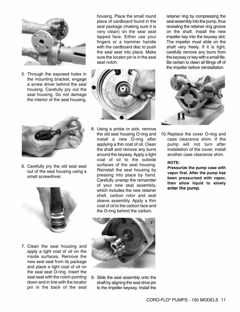
5. Through the exposed holes inthe mounting bracket, engagea screw driver behind the sealhousing. Carefully pry out theseal housing. Do not damagethe interior of the seal housing.
6. Carefully pry the old seal seatout of the seal housing using asmall screwdriver.
7. Clean the seal housing andapply a light coat of oil on theinside surfaces. Remove thenew seal seat from its packageand place a light coat of oil onthe seal seat O-ring. Insert theseal seat with the notch pointingdown and in line with the locatorpin in the back of the seal
housing. Place the small roundpiece of cardboard found in theseal package (making sure it isvery clean) on the seal seatlapped face. Either use yourfingers or a hammer handlewith the cardboard disc to pushthe seal seat into place. Makesure the locator pin is in the sealseat notch.
8. Using a probe or pick, removethe old seal housing O-ring andinstall a new O-ring afterapplying a thin coat of oil. Cleanthe shaft and remove any burrsaround the keyway. Apply a lightcoat of oil to the outsidesurfaces of the seal housing.Reinstall the seal housing bypressing into place by hand.Carefully unwrap the remainderof your new seal assembly,which includes the new retainershell, carbon rotor and sealsleeve assembly. Apply a thincoat of oil to the carbon face andthe O-ring behind the carbon.
9. Slide the seal assembly onto theshaft by aligning the seal drive pinto the impeller keyway. Install the
retainer ring by compressing theseal assembly into the pump, thusrevealing the retainer ring grooveon the shaft. Install the newimpeller key into the keyway slot.The impeller must slide on theshaft very freely. If it is tight,carefully remove any burrs fromthe keyway or key with a small file.Be certain to clean all filings off ofthe impeller before reinstallation.
10.Replace the cover O-ring andcase clearance shim. If thepump will not turn afterinstallation of the cover, installanother case clearance shim.
NOTE:Pressurize the pump case withvapor first. After the pump hasbeen pressurized with vapor,then allow liquid to slowlyenter the pump.

PARTS DETAILSCORO-FLO® PUMPS – 150 MODELS
FRAME MOUNTANSI FLANGE (FF) AND DIN FLANGE (FD)
12 CORO-FLO® PUMPS - 150 MODELS
5
12
327
25
23
4
29
24
10
20
28
306
13
21
19
7,8
312
118
9
22
16
17
1511
26
25 ft•lb (33.9 N•m)Torque
14 60 ft•lb (81.4 N•m)Torque
32
CAUTION: Always relieve pressure in the unitbefore attempting any repairs.
NO PART NO DESCRIPTION QTY
1 1006 GREASE SEAL 12 1238 BEARING CAP 13 1914-1 NAMEPLATE 14 2-018__ SEAL SLEEVE O-RING1, 2 15 2-133__ SEAL HOUSING O-RING1, 2 16 2-260__ CASE O-RING1, 2 17 2158 GREASE ZERK 28 2159 LUBRICAP 29 2758 DOUBLE ROW BALL BEARING 1
10 2760-88 7/8” RETAINER RING2 111 3226 SHAFT KEY 112 3442 1/4” PIPE PLUG 213 4244 IMPELLER KEY2 114 1010-3 MOUNTING FRAME 115 3227 BEARING PLATE3 116 2759 SINGLE ROW BALL BEARING 1
NO PART NO DESCRIPTION QTY
17 5000-281 RETAINER RING 118 5102-118 RETAINER RING 119 5238 CASE - ANSI FLANGE (FF) 119 5238-1 CASE - DIN FLANGE (FD) 120 5239 COVER 121 5240 IMPELLER 122 5241-1 SHAFT 123 5242-X SEAL2,3 124 5243 SEAL SLEEVE2 125 5244 SEAL HOUSING 126 7302-100MC020A M10-1.5 x 22MM ALLEN HEAD BOLT 427 7012-0065F019E NAMEPLATE SCREW 228 7301-140MC040A M14-2 x 40MM HEX HEAD BOLT 429 4984 SEAL DRIVE PIN2 130 5248 CASE CLEARANCE SHIM2 131 5002-281 RETAINER RING 132 5264-X_3 SEAL ASSEMBLY1 1
O-ring Code
A Buna-NB Neoprene®
D Viton®
E Teflon®
G Etylene-PropyleneK Kalrez®
1 __ denotes O-ring code2 Included in seal assembly 5264-X__3 3 Not sold separately
® Registered trademarks of theDuPont Company
CORO-FLO® PUMPS - 150 MODELS 13
525
4
29
24
10
20
28
60 ft•lb (81.4 N•m)Torque
306
13
21
312
118
9
22
1617
7,826
1415
11
327
12
19
23
25 ft•lb (33.9 N•m)Torque
32
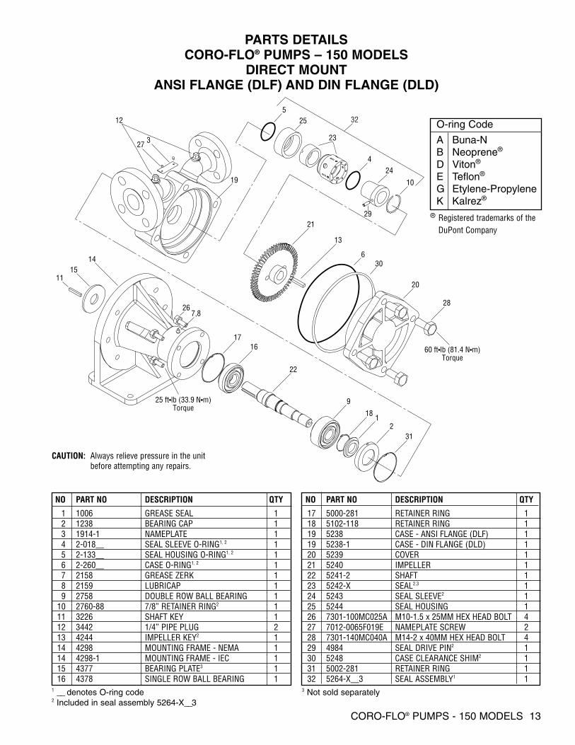
NO PART NO DESCRIPTION QTY
1 1006 GREASE SEAL 12 1238 BEARING CAP 13 1914-1 NAMEPLATE 14 2-018__ SEAL SLEEVE O-RING1, 2 15 2-133__ SEAL HOUSING O-RING1, 2 16 2-260__ CASE O-RING1, 2 17 2158 GREASE ZERK 18 2159 LUBRICAP 19 2758 DOUBLE ROW BALL BEARING 1
10 2760-88 7/8” RETAINER RING2 111 3226 SHAFT KEY 112 3442 1/4” PIPE PLUG 213 4244 IMPELLER KEY2 114 4298 MOUNTING FRAME - NEMA 114 4298-1 MOUNTING FRAME - IEC 115 4377 BEARING PLATE3 116 4378 SINGLE ROW BALL BEARING 1
NO PART NO DESCRIPTION QTY
17 5000-281 RETAINER RING 118 5102-118 RETAINER RING 119 5238 CASE - ANSI FLANGE (DLF) 119 5238-1 CASE - DIN FLANGE (DLD) 120 5239 COVER 121 5240 IMPELLER 122 5241-2 SHAFT 123 5242-X SEAL2,3 124 5243 SEAL SLEEVE2 125 5244 SEAL HOUSING 126 7301-100MC025A M10-1.5 x 25MM HEX HEAD BOLT 427 7012-0065F019E NAMEPLATE SCREW 228 7301-140MC040A M14-2 x 40MM HEX HEAD BOLT 429 4984 SEAL DRIVE PIN2 130 5248 CASE CLEARANCE SHIM2 131 5002-281 RETAINER RING 132 5264-X__3 SEAL ASSEMBLY1 1
CAUTION: Always relieve pressure in the unitbefore attempting any repairs.
1 __ denotes O-ring code2 Included in seal assembly 5264-X__3
3 Not sold separately
PARTS DETAILSCORO-FLO® PUMPS – 150 MODELS
DIRECT MOUNTANSI FLANGE (DLF) AND DIN FLANGE (DLD)
O-ring Code
A Buna-NB Neoprene®
D Viton®
E Teflon®
G Etylene-PropyleneK Kalrez®
® Registered trademarks of theDuPont Company
14 CORO-FLO® PUMPS - 150 MODELS
5 ft (1.5 m)maximum
Underground tank
9
6
7
10
2
1
3
4
11
55
14 ft (4.3 m)maximum
8
Minimum liquid level of12 in (304 mm)
above endof dip tube
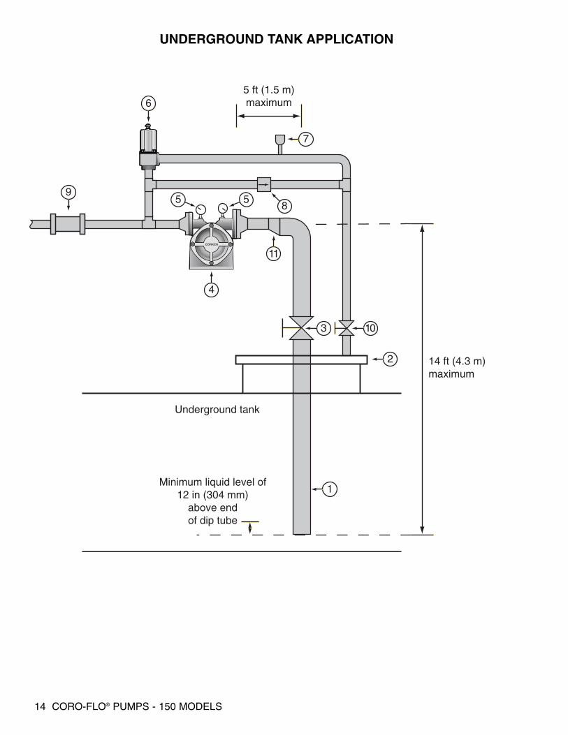
UNDERGROUND TANK APPLICATION

CORO-FLO® PUMPS - 150 MODELS 15
REF. NO. DESCRIPTION REMARKS
1 2”, schedule 80 pipe
2 Man way Cover Existing
3 2” ball valve, full port Manual or remote control
4 Corken 150 Series pump With 7.5 hp (5.5 kW) electric motor
5 1/4” NPT pressure gauge 0-400 psig (0-28 bar g)
6 Corken B166 By-Pass Valve 1” NPT With spring code C
7 1/4” NPT hydrostatic relief valve Set at 450 psig (31 bar g)
8 In-line excess flow valve Closing flow of 10-15 gpm (37-57 L/min)
9 Back pressure check valve Like Corken’s Flo-Chek valve
10 By-pass return line’s valve Existing
11 2” x 1-1/2” eccentric reducer
BILL OF MATERIALS
WARNING:1. No excess flow valves on the tank’s liquid outlet connections are shown in these schematics. If local
regulations require the use of excess flow valves, its closing flow should be approximately 1.5 timeshigher than the pump’s rated capacity for the operational conditions.
2. Periodic inspection and maintenance of Corken products is essential.
3. Only experienced, trained and qualified personnel are to make inspection, maintenance andinstallation of Corken products.
4. Maintenance, use and installation of Corken products must comply with Corken instructions,applicable laws and safety standards such as NFPA 58 for LP-Gas and ANSI K6.1-1972 forAnhydrous Ammonia.
5. Transfer of toxic, dangerous, flammable or explosive substances using Corken equipment is at theuser’s risk. Only qualified personnel should operate Corken equipment according to the applicablelaws and safety standards.
16 CORO-FLO® PUMPS - 150 MODELS
Minimum liquid level of12 in (304 mm)
above endof dip tube
5 ft (1.5 m)maximum
Underground tank
9
4
8
13
11
3
1
2 10
1214
76
55
14 ft (4.3 m)maximum
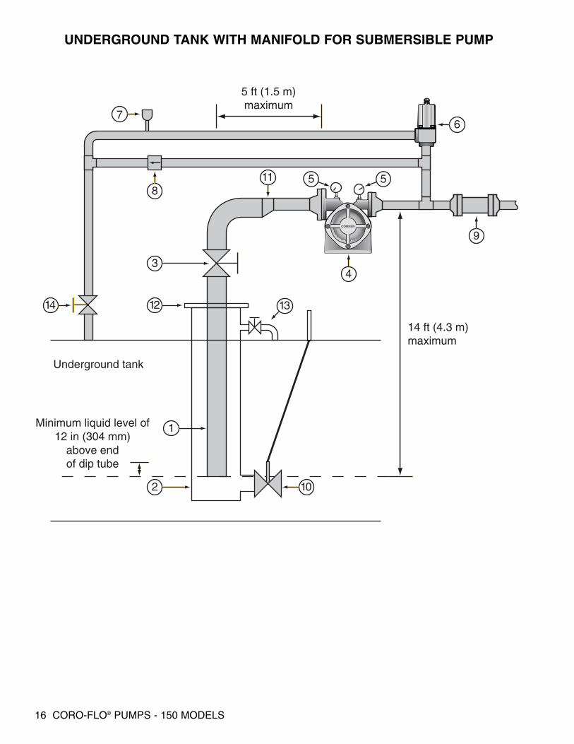
UNDERGROUND TANK WITH MANIFOLD FOR SUBMERSIBLE PUMP
CORO-FLO® PUMPS - 150 MODELS 17
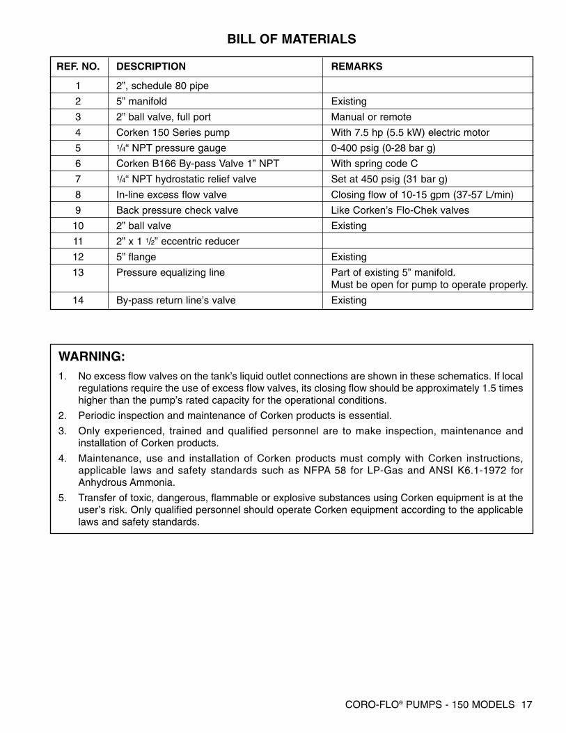
BILL OF MATERIALS
REF. NO. DESCRIPTION REMARKS
1 2”, schedule 80 pipe
2 5” manifold Existing
3 2” ball valve, full port Manual or remote
4 Corken 150 Series pump With 7.5 hp (5.5 kW) electric motor
5 1/4“ NPT pressure gauge 0-400 psig (0-28 bar g)
6 Corken B166 By-pass Valve 1” NPT With spring code C
7 1/4“ NPT hydrostatic relief valve Set at 450 psig (31 bar g)
8 In-line excess flow valve Closing flow of 10-15 gpm (37-57 L/min)
9 Back pressure check valve Like Corken’s Flo-Chek valves
10 2” ball valve Existing
11 2” x 1 1/2” eccentric reducer
12 5” flange Existing
13 Pressure equalizing line Part of existing 5” manifold.Must be open for pump to operate properly.
14 By-pass return line’s valve Existing
WARNING:1. No excess flow valves on the tank’s liquid outlet connections are shown in these schematics. If local
regulations require the use of excess flow valves, its closing flow should be approximately 1.5 timeshigher than the pump’s rated capacity for the operational conditions.
2. Periodic inspection and maintenance of Corken products is essential.
3. Only experienced, trained and qualified personnel are to make inspection, maintenance andinstallation of Corken products.
4. Maintenance, use and installation of Corken products must comply with Corken instructions,applicable laws and safety standards such as NFPA 58 for LP-Gas and ANSI K6.1-1972 forAnhydrous Ammonia.
5. Transfer of toxic, dangerous, flammable or explosive substances using Corken equipment is at theuser’s risk. Only qualified personnel should operate Corken equipment according to the applicablelaws and safety standards.

18 CORO-FLO® PUMPS - 150 MODELS
3
1
5
2
4
No! Yes!
No!
No!
CORKEN
INL
ET
OU
TL
ET
CORKEN
INL
ET
OU
TL
ET
CORKEN
INL
ET
OU
TL
ET
CORKEN
INL
ET
OU
TL
ET
CORKEN
INL
ET
OU
TL
ET
CORKEN
INL
ET
OU
TL
ET
Yes!
CORKEN
INL
ET
OU
TL
ET
CORKEN
INL
ET
OU
TL
ET
CORKEN
INL
ET
OU
TL
ET
CORKEN
INL
ET
OU
TL
ET
6
CORKEN
INL
ET
OU
TL
ET
Yes!
CORKEN
INL
ET
OU
TL
ET
Do not use restricted inlet line! Use inlet line larger than pump suction nozzle. Same size nozzle OK on short runs.
Concentric Reducer Eccentric Reducer
Do not allow bypass line to have low spot.
Keep return line level or go up toward tank!
Pressure drop caused by restriction in suction line will cause vaporization and cavitation.
An eccentric reducer should always be used when reducing into any pump inlet where vapor might beencountered in the pumpage. The flat upper portion of the reducer prevents an accumulation of vapor thatcould interfere with pumping action.
Low spots in bypass line can collect liquid which prevents normal vapor passage for priming purposes just like the P trap in the drain of a kitchen sink. This is not a problem for bypass lines where vapor elimination is not required.
ABOVE GROUND INSTALLATION TIPS
CORO-FLO® PUMPS - 150 MODELS 19
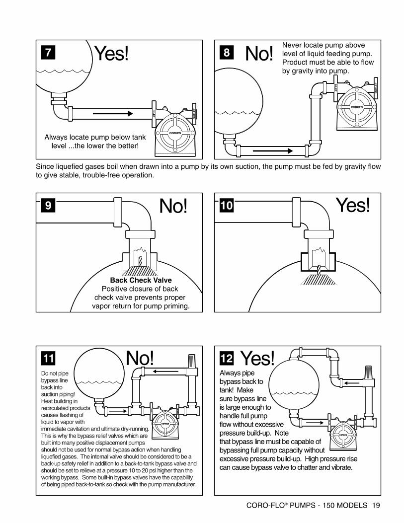
No! Yes!
Yes!
9 10
CORKEN
INL
ET
OU
TL
ET
7 Yes!
CORKEN
INL
ET
OU
TL
ET
CORKEN
INL
ET
OU
TL
ET
8 No!
CORKEN
INL
ET
OU
TL
ET
No!11
CORKEN
OU
TL
ETIN
LE
T
CORKEN
OU
TL
ET
CORKEN
OU
TL
ETIN
LE
T
12
Always locate pump below tanklevel ...the lower the better!
Never locate pump abovelevel of liquid feeding pump. Product must be able to flow by gravity into pump.
Back Check ValvePositive closure of back
check valve prevents proper vapor return for pump priming.
Do not pipe bypass line back into suction piping! Heat building in recirculated products causes flashing of liquid to vapor with immediate cavitation and ultimate dry-running. This is why the bypass relief valves which are built into many positive displacement pumps should not be used for normal bypass action when handling liquefied gases. The internal valve should be considered to be a back-up safety relief in addition to a back-to-tank bypass valve and should be set to relieve at a pressure 10 to 20 psi higher than the working bypass. Some built-in bypass valves have the capability of being piped back-to-tank so check with the pump manufacturer.
Always pipe bypass back to tank! Make sure bypass line is large enough to handle full pump flow without excessive pressure build-up. Note that bypass line must be capable of bypassing full pump capacity without excessive pressure build-up. High pressure rise can cause bypass valve to chatter and vibrate.
Since liquefied gases boil when drawn into a pump by its own suction, the pump must be fed by gravity flowto give stable, trouble-free operation.

20 CORO-FLO® PUMPS - 150 MODELS
CORKEN
INL
ET
OU
TL
ET
CORKEN
INL
ET
OU
TL
ET
13
Do not place pump far from tank!
No!
CORKEN
INL
ET
OU
TL
ET
CORKEN
INL
ET
OU
TL
ET
Locate pump close to tank!Directly under is best.
Yes!
14
CORKEN
INL
ET
OU
TL
ET
CORKEN
INL
ET
OU
TL
ET
CORKEN
INL
ET
OU
TL
ET
CORKEN
INL
ET
OU
TL
ET
No!
Do not locate restrictive fittingsor elbows close to pump inlet.
15
10D
D
Yes!
Best rule is 10 pipe diametersstraight pipe upstream frompump! Not always possible.
CORKEN
INL
ET
OU
TL
ET
CORKEN
INL
ET
OU
TL
ET
16
On vaporizer feed pumps, a back check valve should be installed between the pump and to prevent back-flow of vapor from entering pump.
No! Best1817
To Vaporizer
To Vaporizer
A B
CORKEN
INL
ET
OU
TL
ET
CORKEN
INL
ET
OU
TL
ET
Where A is a constantpressure bypass control valve and B isCorken B166 bypass and vapor elimination valve.
Valve A is a fixed pressure bypass like the Fisher 98H which limits the feed pressure into the vaporizer to a specific value regardless of system vapor pressure. A differential bypass valve like the Corken B166, T166, or B177 controls a fixed difference in pressure between the pump discharge and the tank. Differential valve B must be set to the maximum acceptable differential of the pump while fixed pressure valve A is set for the vaporizer pressure requirement.
CORO-FLO® PUMPS - 150 MODELS 21
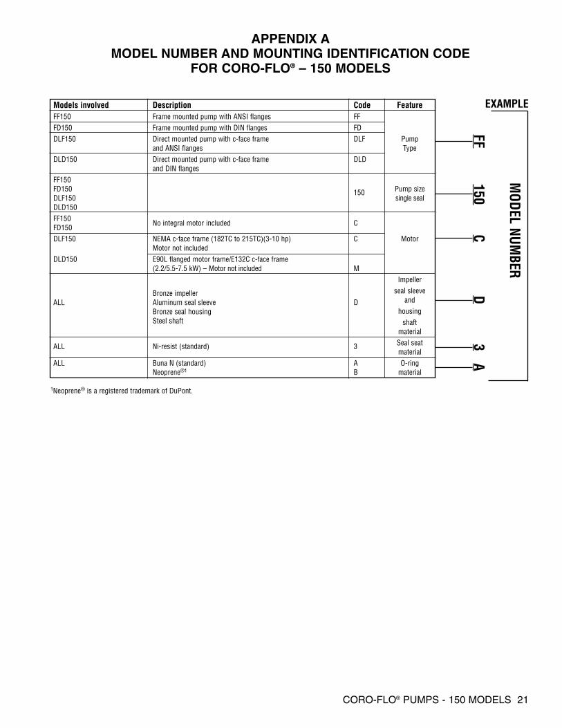
APPENDIX AMODEL NUMBER AND MOUNTING IDENTIFICATION CODE
FOR CORO-FLO® – 150 MODELS
Models involved Description Code FeatureFF150 Frame mounted pump with ANSI flanges FFFD150 Frame mounted pump with DIN flanges FDDLF150 Direct mounted pump with c-face frame DLF Pump
and ANSI flanges TypeDLD150 Direct mounted pump with c-face frame DLD
and DIN flangesFF150FD150 150 Pump sizeDLF150 single sealDLD150FF150
No integral motor included CFD150DLF150 NEMA c-face frame (182TC to 215TC)(3-10 hp) C Motor
Motor not includedDLD150 E90L flanged motor frame/E132C c-face frame
(2.2/5.5-7.5 kW) – Motor not included MImpeller
seal sleeveand
housingshaft
material
ALL Ni-resist (standard) 3 Seal seatmaterial
ALL Buna N (standard) A O-ringNeoprene®1 B material
FF150
CD
3A
EXAMPLE
MODEL NUM
BER
1Neoprene® is a registered trademark of DuPont.
Bronze impellerALL Aluminum seal sleeve D
Bronze seal housingSteel shaft
22 CORO-FLO® PUMPS - 150 MODELS
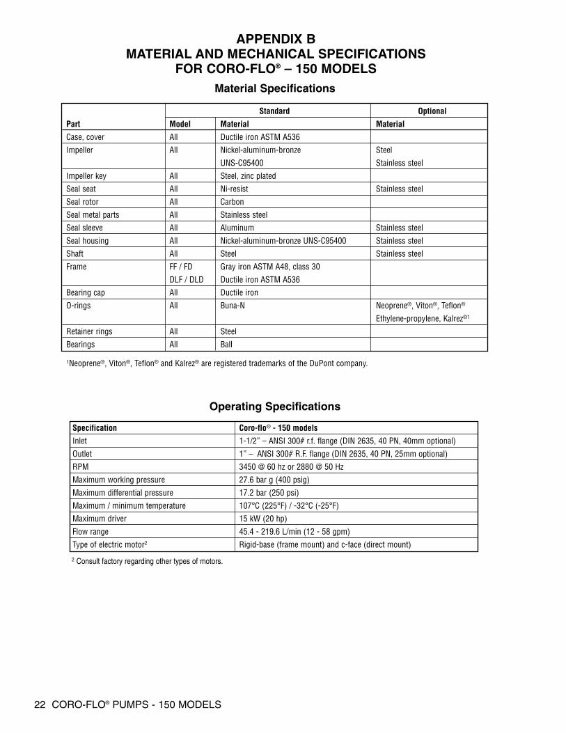
APPENDIX BMATERIAL AND MECHANICAL SPECIFICATIONS
FOR CORO-FLO® – 150 MODELS
Operating Specifications
Material Specifications
Standard Optional
Part Model Material Material
Case, cover All Ductile iron ASTM A536
Impeller All Nickel-aluminum-bronze Steel
UNS-C95400 Stainless steel
Impeller key All Steel, zinc plated
Seal seat All Ni-resist Stainless steel
Seal rotor All Carbon
Seal metal parts All Stainless steel
Seal sleeve All Aluminum Stainless steel
Seal housing All Nickel-aluminum-bronze UNS-C95400 Stainless steel
Shaft All Steel Stainless steel
Frame FF / FD Gray iron ASTM A48, class 30
DLF / DLD Ductile iron ASTM A536
Bearing cap All Ductile iron
O-rings All Buna-N Neoprene®, Viton®, Teflon®
Ethylene-propylene, Kalrez®1
Retainer rings All Steel
Bearings All Ball
1Neoprene®, Viton®, Teflon® and Kalrez® are registered trademarks of the DuPont company.
Specification Coro-flo® - 150 models
Inlet 1-1/2” – ANSI 300# r.f. flange (DIN 2635, 40 PN, 40mm optional)
Outlet 1” – ANSI 300# R.F. flange (DIN 2635, 40 PN, 25mm optional)
RPM 3450 @ 60 hz or 2880 @ 50 Hz
Maximum working pressure 27.6 bar g (400 psig)
Maximum differential pressure 17.2 bar (250 psi)
Maximum / minimum temperature 107°C (225°F) / -32°C (-25°F)
Maximum driver 15 kW (20 hp)
Flow range 45.4 - 219.6 L/min (12 - 58 gpm)
Type of electric motor2 Rigid-base (frame mount) and c-face (direct mount)
2 Consult factory regarding other types of motors.
CORO-FLO® PUMPS - 150 MODELS 23
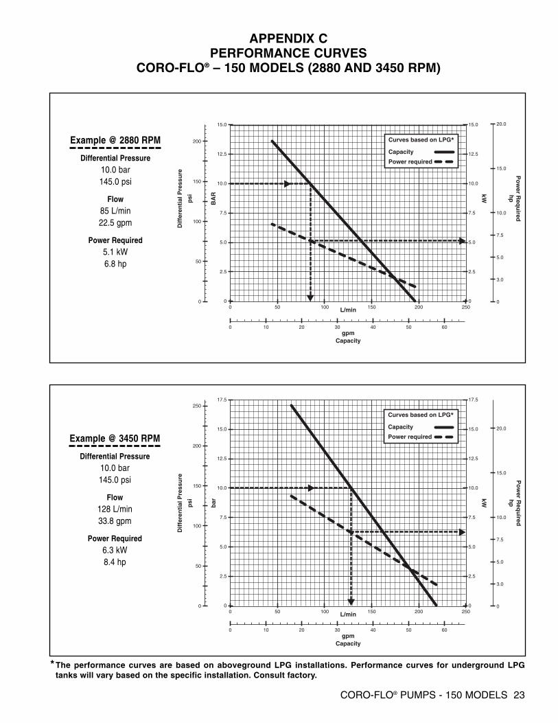
APPENDIX CPERFORMANCE CURVES
CORO-FLO® – 150 MODELS (2880 AND 3450 RPM)
0 50 100 150 200 2500
50
100
150
200
0
2.5
5.0
7.5
10.0
12.5
15.0
0
2.5
5.0
7.5
10.0
12.5
15.0
0
3.0
5.0
7.5
10.0
15.0
20.0
gpmCapacity
L/min
hp
kW
Dif
fere
nti
al P
ress
ure
psi
BA
R
Curves based on LPG*Capacity
Power required
0 10 20 30 40 50 60
Po
wer R
equ
ired
0
0 10 20 30 40 50 60
50 100 150 200 2500
50
100
150
200
250
0
2.5
5.0
7.5
10.0
12.5
15.0
17.5
0
2.5
5.0
7.5
10.0
12.5
15.0
17.5
0
3.0
5.0
7.5
10.0
15.0
20.0
gpmCapacity
L/min
hp
kW
Dif
fere
nti
al P
ress
ure
psi
Po
wer R
equ
ired
bar
Curves based on LPG*Capacity
Power required
Example @ 2880 RPM
Differential Pressure10.0 bar145.0 psi
Flow85 L/min22.5 gpm
Power Required5.1 kW6.8 hp
Example @ 3450 RPM
Differential Pressure10.0 bar145.0 psi
Flow128 L/min33.8 gpm
Power Required6.3 kW8.4 hp
*The performance curves are based on aboveground LPG installations. Performance curves for underground LPGtanks will vary based on the specific installation. Consult factory.
24 CORO-FLO® PUMPS - 150 MODELS
1/4" NPT 1/4" NPT
1/4 (.63) SQUARE KEYWAY
INLE
T
OU
TL
ET
CORKEN
(11.45)4-1/2
(11.45)4-1/2
(11.45)4-1/2
(2.54)1D
(12.23)4-13/16
(13.57)5-11/32
(15.25)6
(5.25)2-1/16
(5.25)2-1/16
(2.30)29/32
(10.17)4
(13.96)5-1/2
AINLET
BOUTLET
DIMENSIONS IN INCHES (CENTIMETERS)
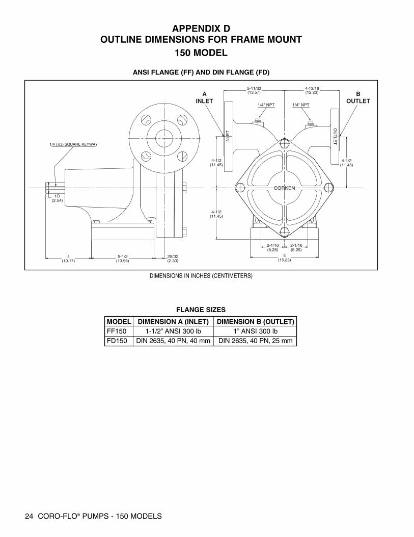
ANSI FLANGE (FF) AND DIN FLANGE (FD)
FLANGE SIZES
MODEL DIMENSION A (INLET) DIMENSION B (OUTLET)FF150 1-1/2” ANSI 300 lb 1” ANSI 300 lbFD150 DIN 2635, 40 PN, 40 mm DIN 2635, 40 PN, 25 mm
APPENDIX DOUTLINE DIMENSIONS FOR FRAME MOUNT
150 MODEL

CORO-FLO® PUMPS - 150 MODELS 25
APPENDIX EOUTLINE DIMENSIONS FOR AND DIRECT MOUNT
150 MODEL
NOTES:MOUNTING FOR NEMA AND IECC-FACE MOTORS - SEE TABLEMOUNTING DIMENSIONS
4 - 13/32 (1.03) DIA. HOLESIN
LET
OU
TLE
T
(19.27)7-19/32
(11.42)4-1/2(9.84)
3-7/8(9.84)3-7/8
(13.65)5-3/8
(11.43)4-1/2
(11.43)4-1/2
(.62)1/4
(23.50)9-1/4
A
BC
EOUTLET
DINLET
(25.4)1
(12.23)4-13/16
(13.57)5-11/32
DIMENSIONS IN INCHES (CENTIMETERS)
MOTOR MOUNTING DIMENSIONS
DIMENSION A DIMENSION B DIMENSION CNEMA 8-1/2” 7-1/4” 3-13/16”IEC 165 mm 130 mm 90.75 mm
ANSI FLANGE (DLF) AND DIN FLANGE (DLD)
FLANGE SIZES
MODEL DIMENSION D (INLET) DIMENSION E (OUTLET)DLF150 1-1/2” ANSI 300 lb 1” ANSI 300 lbDLD150 DIN 2635, 40 PN, 40 mm DIN 2635, 40 PN, 25 mm
(9.84)3-7/8
(9.84)3-7/8
(13.65)5 3/8
(11.43)4-1/2
(11.43)4-1/2
(23.50)9-1/4
(12.23)4-13/16
(13.57)5-11/32
INL
ET
OU
TLE
T
CORKEN
EOUTLET
DINLET
26 CORO-FLO® PUMPS - 150 MODELS
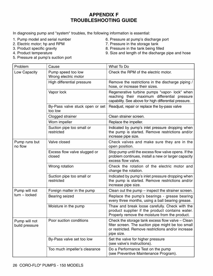
APPENDIX FTROUBLESHOOTING GUIDE
1. Pump model and serial number2. Electric motor; hp and RPM3. Product specific gravity4. Product temperature5. Pressure at pump’s suction port
6. Pressure at pump’s discharge port7. Pressure in the storage tank8. Pressure in the tank being filled9. Size and length of the discharge pipe and hose
Problem
Low Capacity
Pump runs but no flow
Pump will notturn – locked
Pump will notbuild pressure
Cause
Pump speed too lowWrong electric motor
High differential pressure
Vapor lock
By-Pass valve stuck open or settoo low
Clogged strainer
Worn impeller
Suction pipe too small orrestricted
Valve closed
Excess flow valve slugged orclosed
Wrong rotation
Suction pipe too small orrestricted
Foreign matter in the pump
Bearing seized
Moisture in the pump
Poor suction conditions
By-Pass valve set too low
Too much impeller’s clearance
What To Do
Check the RPM of the electric motor.
Remove the restrictions in the discharge piping /hose, or increase their sizes.
Regenerative turbine pumps "vapor- lock" whenreaching their maximum differential pressurecapability. See above for high differential pressure.
Readjust, repair or replace the by-pass valve
Clean strainer screen.
Replace the impeller.
Indicated by pump’s inlet pressure dropping whenthe pump is started. Remove restrictions and/orincrease pipe size.
Check valves and make sure they are in theopen position.
Stop pump until the excess flow valve opens. If theproblem continues, install a new or larger capacityexcess flow valve.
Check the rotation of the electric motor andchange the rotation.
Indicated by pump’s inlet pressure dropping whenthe pump is started. Remove restrictions and/orincrease pipe size.
Clean out the pump – inspect the strainer screen.
Replace the pump’s bearings - grease bearingevery three months, using a ball bearing grease.
Thaw and break loose carefully. Check with theproduct supplier if the product contains water.Properly remove the moisture from the product.
Check the storage tank excess flow valve – Cleanfilter screen. The suction pipe might be too smallor restricted. Remove restrictions and/or increasepipe size.
Set the valve for higher pressure(see valve’s instructions).
Do a Performance Test on the pump(see Preventive Maintenance Program).
In diagnosing pump and "system" troubles, the following information is essential:
CORO-FLO® PUMPS - 150 MODELS 27
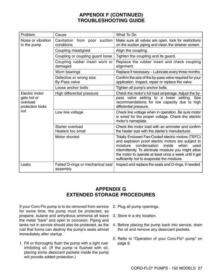
Problem
Noise or vibrationin the pump
Electric motorgets hot oroverloadprotection kicksout
Leaks
Cause
Cavitation from poor suctionconditions
Coupling misaligned
Coupling or coupling guard loose
Coupling rubber insert worn ordamaged
Worn bearings
Defective or wrong sizeBy-Pass valve
Loose anchor bolts
High differential pressure
Low line voltage
Starter overloadHeaters too small
Motor shorted
Failed O-rings or mechanical sealassembly
What To Do
Make sure all valves are open, look for restrictionson the suction piping and clean the strainer screen.
Align the coupling.
Tighten the coupling and its guard.
Replace the rubber insert and check couplingalignment.
Replace if necessary – Lubricate every three months.
Confirm the size of the by-pass valve required for yourapplication. Inspect, repair or replace the valve.
Tighten all pump’s anchor bolts.
Check the motor’s full load amperage. Adjust the by-pass valve setting to a lower setting. Seerecommendations for low capacity due to highdifferential pressure.
Check line voltage when in operation. Be sure motoris wired for the proper voltage. Check the electricmotor’s nameplate.
Check the motor load with an ammeter and confirmthe heater size with the starter’s manufacturer.
Totally Enclosed Fan-Cooled electric motors (TEFC)and explosion proof electric motors are subject tomoisture condensation inside when usedintermittently. To eliminate moisture you might allowthe motor to operate at least once a week until it getsufficiently hot to evaporate the moisture.
Inspect and replace the seals and O-rings, if needed.
APPENDIX F (CONTINUED)TROUBLESHOOTING GUIDE
If your Coro-Flo pump is to be removed from servicefor some time, the pump must be protected, aspropane, butane and anhydrous ammonia all leavethe metal “bare” and open to corrosion. Piping andtanks not in service should also be protected, as therust that forms can destroy the pump’s seals almostimmediately after startup.
1. Fill or thoroughly flush the pump with a light rust-inhibiting oil. (If the pump is flushed with oil,placing some desiccant packets inside the pumpwill provide added protection.)
2. Plug all pump openings.
3. Store in a dry location.
4. Before placing the pump back into service, drainthe oil and remove any desiccant packets.
5. Refer to “Operation of your Coro-Flo® pump” onpage 8.
APPENDIX GEXTENDED STORAGE PROCEDURES

Corken, Inc. • A Unit of IDEX Corporation
P.O. Box 12338, Oklahoma City, OK 73157 U.S.A.3805 N.W. 36th St., Oklahoma City, OK 73112Phone (405) 946-5576 • Fax (405) 948-7343
Visit our website at http://www.corken.come-mail us at [email protected]
Printed in the U.S.A.May 2003