INSTALLATION, OPERATION & MAINTENANCE MANUAL · 2015-08-25 · DVB SERIES Gas Fired Boilers For...
44
DVB SERIES Gas Fired Boilers For Forced Hot Water INSTALLATION, OPERATION & MAINTENANCE MANUAL P/N 37615501, Rev. D [08/2011] An ISO 9001-2008 Certified Company Utica Boilers 2201 Dwyer Avenue • Utica • New York • 13504 • USA www.ecrinternational.com
Transcript of INSTALLATION, OPERATION & MAINTENANCE MANUAL · 2015-08-25 · DVB SERIES Gas Fired Boilers For...

DVB SERIES
Gas Fired Boilers For Forced Hot Water
INSTALLATION, OPERATION & MAINTENANCE MANUAL
P/N 37615501, Rev. D [08/2011]An ISO 9001-2008 Certified Company
Utica Boilers2201 Dwyer Avenue • Utica • New York • 13504 • USAwww.ecrinternational.com
2
KEEP THIS MANUAL NEAR BOILER ANDRETAIN FOR FUTURE REFERENCE.
Tested for 100 psi. ASME Working Pressure
HC.S.A. Certifi ed for
Natural gas or Propane
SAFETY SYMBOLS
IMPORTANT: Read the following instructions COMPLETELY before installing!
The following defi ned symbols are used throughout this manual to notify the reader of potential hazards of varying risk levels.
Introduction ................................................................................................................................ 3
Boiler Ratings, Capacities & Dimensions .......................................................................................... 4
Ventilation & Combustion Air ......................................................................................................... 6
Connecting Supply & Return Piping ................................................................................................ 7
Applicable Federal Codes .............................................................................................................11
Vent System Modifi cation .............................................................................................................11
Horizontal Vent Pipe Installation Instructions ..................................................................................12
Vertical Vent Pipe Installation Instructions ......................................................................................22
Connecting Gas Service ...............................................................................................................28
Electrical Wiring .........................................................................................................................29
Lighting Instructions ...................................................................................................................31
Sequence Of Operation................................................................................................................32
General Instruction For Seasonal Startup & Maintenance ..................................................................33
Replacement Parts ......................................................................................................................37
GAS FIRED BOILERS FOR FORCED HOT WATER
! DANGER
Indicates a hazardous situation which, if not avoided, WILL result in death or serious injury.
! CAUTION
Indicates a hazardous situation which, if not avoided, may result in minor or moderate injury.
! WARNING
Indicates a hazardous situation which, if not avoided, could result in death or serious injury.
NOTICE
Indicates information which should be followed to ensure proper installation and operation.
3
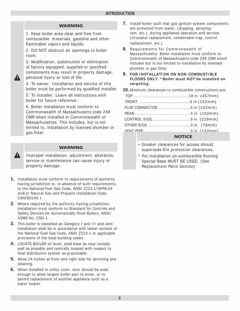
Installation must conform to requirements of authority 1. having jurisdiction or, in absence of such requirements, to the National Fuel Gas Code, ANSI Z223.1/NFPA 54 and/or Natural Gas and Propane Installation Code, CAN/BS149.1Where required by the authority having jurisdiction, 2. installation must conform to Standard for Controls and Safety Devices for Automatically Fired Boilers, ANSI/ASME No. CSD-1.This boiler is classifi ed as Category I and III and vent 3. installation shall be in accordance with latest revision of the National Fuel Gas Code, ANSI Z223.1 or applicable provisions of the local building codes.LOCATE BOILER on level, solid base as near outside 4. wall as possible and centrally located with respect to heat distribution system as practicable.Allow 24 inches at front and right side for servicing and 5. cleaning.When installed in utility room, door should be wide 6. enough to allow largest boiler part to enter, or to permit replacement of another appliance such as a water heater.
Install boiler such that gas ignition system components 7. are protected from water, (dripping, spraying, rain, etc.), during appliance operation and service, (circulator replacement, condensate trap, control replacement, etc.). Requirements for Commonwealth of 8. Massachusetts: Boiler installation must conform to Commonwealth of Massachusetts code 248 CMR which includes but is not limited to installation by licensed plumber or gas fi tter.FOR INSTALLATION ON NON-COMBUSTIBLE 9. FLOORS ONLY. *Boiler must NOT be installed on carpeting.
Minimum clearances to combustible constructions are:10. TOP ...........................................18 in. (457mm) FRONT ........................................6 in (152mm)FLUE CONNECTOR .........................6 in (152mm)REAR............................................4 in. (102mm)CONTROL SIDE..............................9 in. (229mm)OTHER SIDE .................................3 in. (76mm)VENT PIPE ....................................6 in. (152mm)
INTRODUCTION
!
WARNING
1. Keep boiler area clear and free from combustible materials, gasoline and other fl ammable vapors and liquids.2. DO NOT obstruct air openings to boiler room.3. Modifi cation, substitution or elimination of factory equipped, supplied or specifi ed components may result in property damage, personal injury or loss of life.4. To owner: Installation and service of this boiler must be performed by qualifi ed installer.5. To installer: Leave all instructions with boiler for future reference.6. Boiler installation must conform to Commonwealth of Massachusetts code 248 CMR when installed in Commonwealth of Massachusettes. This includes, but is not limited to, installation by licensed plumber or gas fi tter.
! WARNING
Improper installation, adjustment, alteration, service or maintenance can cause injury or property damage.
NOTICE
• Greater clearances for access should supersede fi re protection clearances.
* For installation on combustible fl ooring Special Base MUST BE USED. (See Replacement Parts Section)

4
Table 1- DIMENSIONS FOR NATURAL GAS
Model # Natural Gas Inlet
Dimensions Pump size
Supply & Return
Tappings
A B C D E
-50 ½" 11¼ 2⅛ 3 6⅜ 27 1¼"
-100 ½" 15⅛ 4⅛ 3 6⅜ 27 1¼"
-125 ½" 19 6 3 6⅜ 27 1¼"
-150 ½" 19 6 4 6⅜ 27 1¼"
-200 ½" 22⅞ 8 4 7 28 1¼"
NOTE: For altitudes above 2,000 ft. ratings should be reduced at the rate of 4% for
each 1,000 ft. above sea level.
BOILER RATINGS, CAPACITIES & DIMENSIONS
!
WARNING
All installations of boilers and venting should be done only by a qualifi ed expert and in accordance with the appropriate utica boilers manual. Installing or venting a boiler or any other gas appliance with improper methods or materials may result in serious injury or death due to fi re or to asphyxiation from poisonous gases such as carbon monoxide which is odorless and invisible.
Figure 1 -Boiler Dimensions
5
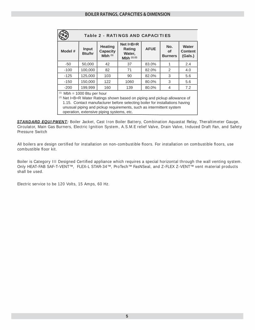
Table 2 - RATINGS AND CAPACITIES
Model # InputBtu/hr
HeatingCapacity
Mbh (1)
Net I=B=R Rating Water,
Mbh (1) (2)
AFUE No.of
Burners
WaterContent(Gals.)
-50 50,000 42 37 83.0% 1 2.4-100 100,000 82 71 82.0% 2 4.0-125 125,000 103 90 82.0% 3 5.6-150 150,000 122 1060 80.0% 3 5.6-200 199,999 160 139 80.0% 4 7.2
(1) Mbh = 1000 Btu per hour(2) Net I=B=R Water Ratings shown based on piping and pickup allowance of
1.15. Contact manufacturer before selecting boiler for installations having unusual piping and pickup requirements, such as intermittent system operation, extensive piping systems, etc.
STANDARD EQUIPMENT: Boiler Jacket, Cast Iron Boiler Battery, Combination Aquastat Relay, Theraltimeter Gauge, Circulator, Main Gas Burners, Electric Ignition System, A.S.M.E relief Valve, Drain Valve, Induced Draft Fan, and Safety Pressure Switch
All boilers are design certifi ed for installation on non-combustible fl oors. For installation on combustible fl oors, use combustible fl oor kit.
Boiler is Category III Designed Certifi ed appliance which requires a special horizontal through the wall venting system. Only HEAT-FAB SAF-T-VENT™, FLEX-L STAR-34™, ProTech™ FasNSeal, and Z-FLEX Z-VENT™ vent material products shall be used.
Electric service to be 120 Volts, 15 Amps, 60 Hz.
BOILER RATINGS, CAPACITIES & DIMENSION

6
VENTILATION & COMBUSTION AIR
Provide combustion air and ventilation air in accordance with the section “Air for Combustion and Ventilation,” of the National Fuel Gas Code, ANSI Z223.1/NFPA 54, or Sections 8.2, 8.3 or 8.4 of Natural Gas and Propane Installation Code, CAN/CSA B149.1, or applicable provisions of local building codes.
Provide make-up air where exhaust fans, clothes dryers, and kitchen ventilation equipment interfere with proper operation.
National Fuel Gas Code recognizes several methods of obtaining adequate ventilation and combustion air. Requirements of the authority having jurisdiction may override these methods.
Engineered Installations. Must be approved by • authority having jurisdictions.
Mechanical Air Supply. Provide minimum of 0.35 • cfm per Mbh for all appliances located within space. Additional requirements where exhaust fans installed. Interlock each appliance to mechanical air supply system to prevent main burner operation when mechanical air supply system not operating.
All Indoor Air. Calculate minimum volume for all • appliances in space. Use a different method if minimum volume not available.
Standard Method. Cannot be used if known air оinfi ltration rate is less than 0.40 air changes per hour. See Table 3 for space with boiler only. Use equation for multiple appliances.
Volume ≥ 50 ft3 x Total Input [Mbh]Known Air Infi ltration Rate. See о Table 3 for space with boiler only. Use equation for multiple appliances. Do not use an air infi ltration rate (ACH) greater than 0.60.
Volume ≥ 15 ft3/ACH x Total Input [Mbh]Refer to National Fuel Gas Code for opening оrequirements between connection indoor spaces.
All Outdoor Air. Provide permanent opening(s) • communicating directly or by ducts with outdoors.
Two Permanent Opening Method. Provide opening оcommencing within 12 inches of top and second opening commencing within 12 inches of bottom enclosure.
Direct communication with outdoors or communicating through vertical ducts. Provide minimum free area of 1 in2 per 4 Mbh of total input rating of all appliances in enclosure.
Communicating through horizontal ducts. Provide minimum free area of 1 in2 per 2 Mbh of total input rating of all appliances in enclosure.
One Permanent Opening Method. Provide opening оcommencing within 12 inches of top of enclosure. Provide minimum clearance of 1 inch on sides and back and 6 inches on front of boiler (does not supersede clearance to combustible materials).
Combination Indoor and Outdoor Air. Refer to оNational Fuel Gas Code for additional requirements for louvers, grilles, screens and air ducts.
Combination Indoor and Outdoor Air. Refer to • National Fuel Gas Code for application information.
National Gas and Propane Installation Code Requires providing air supply in accordance with:
Section 8.2 and 8.3 when combination of appliances • has a total input of up to and including 400 Mbh (120 kW).
Does not have draft control device. о
Section 8.4 when combination of appliances has total • input exceeding 400 Mbh (120 kW).
Refer to Natural Gas and Propane Installation Code • for specifi c air supply requirements for enclosure or structure where boiler is installed, including air supply openings and ducts.
Table 3
Input Mbh Standard Method
Known Air Infi ltration Rate Method (Air Changes Per Hour)
0.1 0.2 0.3 0.4 0.5 0.6
50 2500 7500 3750 2500 1875 1500 1250
100 5000 15000 7500 5000 3750 3000 2500
125 6250 18750 9375 6250 4688 3750 3125
150 7500 22500 11250 7500 5625 4500 3750
200 10000 30000 15000 10000 7500 6000 5000
7
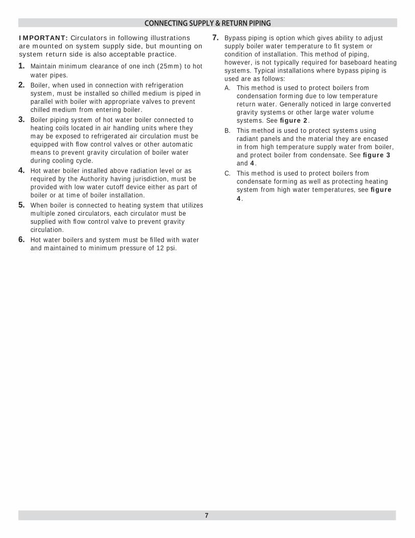
Maintain minimum clearance of one inch (25mm) to hot 1. water pipes.Boiler, when used in connection with refrigeration 2. system, must be installed so chilled medium is piped in parallel with boiler with appropriate valves to prevent chilled medium from entering boiler.Boiler piping system of hot water boiler connected to 3. heating coils located in air handling units where they may be exposed to refrigerated air circulation must be equipped with fl ow control valves or other automatic means to prevent gravity circulation of boiler water during cooling cycle.Hot water boiler installed above radiation level or as 4. required by the Authority having jurisdiction, must be provided with low water cutoff device either as part of boiler or at time of boiler installation.When boiler is connected to heating system that utilizes 5. multiple zoned circulators, each circulator must be supplied with fl ow control valve to prevent gravity circulation.Hot water boilers and system must be fi lled with water 6. and maintained to minimum pressure of 12 psi.
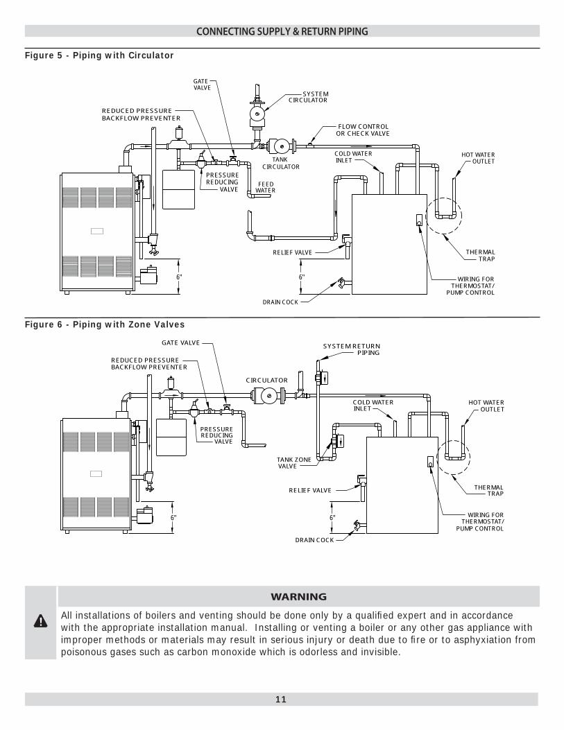
IMPORTANT: Circulators in following illustrations are mounted on system supply side, but mounting on system return side is also acceptable practice.
CONNECTING SUPPLY & RETURN PIPING
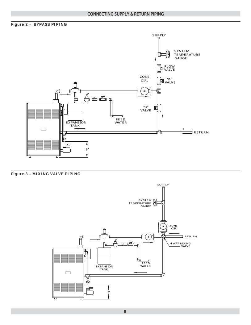
Bypass piping is option which gives ability to adjust 7. supply boiler water temperature to fi t system or condition of installation. This method of piping, however, is not typically required for baseboard heating systems. Typical installations where bypass piping is used are as follows:
This method is used to protect boilers from A. condensation forming due to low temperature return water. Generally noticed in large converted gravity systems or other large water volume systems. See fi gure 2. This method is used to protect systems using B. radiant panels and the material they are encased in from high temperature supply water from boiler, and protect boiler from condensate. See fi gure 3 and 4.This method is used to protect boilers from C. condensate forming as well as protecting heating system from high water temperatures, see fi gure 4.
8
6"
EXPANSIONTANK
TEMPERATURESYSTEM
GAUGE
SUPPLY
RETURN
4 WAY MIXINGVALVE
ZONE CIR.
WATERFEED
Figure 3 - MIXING VALVE PIPING
ZONE CIR.
VALVE
FLOWVALVE
EXPANSIONTANK
VALVE
SYSTEMTEMPERATUREGAUGE
RETURN
SUPPLY
"A"
"B"
6"
FEEDWATER
Figure 2 - BYPASS PIPING
CONNECTING SUPPLY & RETURN PIPING
9
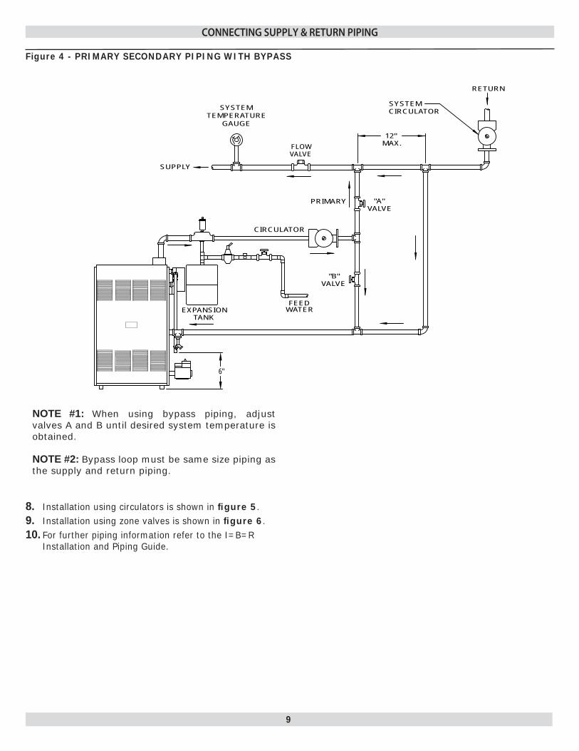
NOTE #1: When using bypass piping, adjust valves A and B until desired system temperature is obtained.
NOTE #2: Bypass loop must be same size piping as the supply and return piping.
Installation using circulators is shown in 8. fi gure 5.Installation using zone valves is shown in 9. fi gure 6.For further piping information refer to the I=B=R 10. Installation and Piping Guide.
CIRCULATOR
VALVE
EXPANSIONTANK
VALVE
RETURN
SUPPLY
12"MAX.
CIRCULATOR
FLOWVALVE
SYSTEMTEMPERATURE
GAUGE
"B"
"A"
SYSTEM
PRIMARY
6"
FEEDWATER
CONNECTING SUPPLY & RETURN PIPING
Figure 4 - PRIMARY SECONDARY PIPING WITH BYPASS
10
WARNING
To avoid burns, scalding, or water damage due to discharge of steam and/or hot water during operation, a discharge line shall be installed to relief valve outlet connection.Discharge line shall:
connect to relief valve outlet and piped down to safe point of disposal. Check local codes for • maximum distance from fl oor or allowable safe point of discharge.
be of pipe size equal to or greater than that of the relief valve outlet over the entire length of • discharge line;
have no intervening shutoff valve between safety relief valve and discharge to atmosphere (do not • plug or place any obstruction in discharge line.
terminate freely to atmosphere where any discharge will be clearly visible and at no risk of freezing;•
allow complete drainage of the valve and the discharge line;•
be independently supported and securely anchored to avoid applied stress on the relief valve;•
be as short and straight as possible;•
terminate with plain end (not threaded);•
be constructed of material suitable for exposure to temperatures of 375° F; or greater.•
Refer to local codes and appropriate ASME Boiler and Pressure Vessel Code for additional installation requirements.
!
WARNING
Burn and scald hazard. Safety relief valve could discharge steam or hot water during operation. Install discharge piping per these instructions.
Install discharge piping from safety relief valve. 11. Use ¾" or larger pipe.•
Use pipe suitable for temperatures of 375°F (191°C) • or greater.
Individual boiler discharge piping shall be independent • of other discharge piping.
Size and arrange discharge piping to avoid reducing • safety relief valve relieving capacity below minimum relief valve capacity stated on rating plate.
Run pipe as short and straight as possible to location • protecting user from scalding and properly drain piping.
Install union, if used, close to safety relief valve outlet.•
Install elbow(s), if used, close to safety relief valve • outlet and downstream of union (if used).
Terminate pipe with plain end (not threaded).•
CONNECTING SUPPLY & RETURN PIPING
11
TANK
SYSTEMCIRCULATOR
CIRCULATOR
REDUCED PRESSUREBACKFLOW PREVENTER
FLOW CONTROLOR CHECK VALVE
OUTLETHOT WATER
TRAPTHERMAL
WIRING FORTHERMOSTAT/
PUMP CONTROL
INLETCOLD WATER
RELIEF VALVE
DRAIN COCK
6" 6"
WATERFEED
PRESSUREREDUCING
VALVE
GATEVALVE
CIRCULATOR
DRAIN COCK
RELIEF VALVE
HOT WATEROUTLET
THERMALTRAP
PUMP CONTROL
WIRING FORTHERMOSTAT/
SYSTEM RETURNPIPING
INLETCOLD WATER
VALVETANK ZONE
6" 6"
PRESSUREREDUCING
VALVE
BACKFLOW PREVENTERREDUCED PRESSURE
GATE VALVE
CONNECTING SUPPLY & RETURN PIPING
Figure 5 - Piping with Circulator
Figure 6 - Piping with Zone Valves
!
WARNING
All installations of boilers and venting should be done only by a qualifi ed expert and in accordance with the appropriate installation manual. Installing or venting a boiler or any other gas appliance with improper methods or materials may result in serious injury or death due to fi re or to asphyxiation from poisonous gases such as carbon monoxide which is odorless and invisible.
12
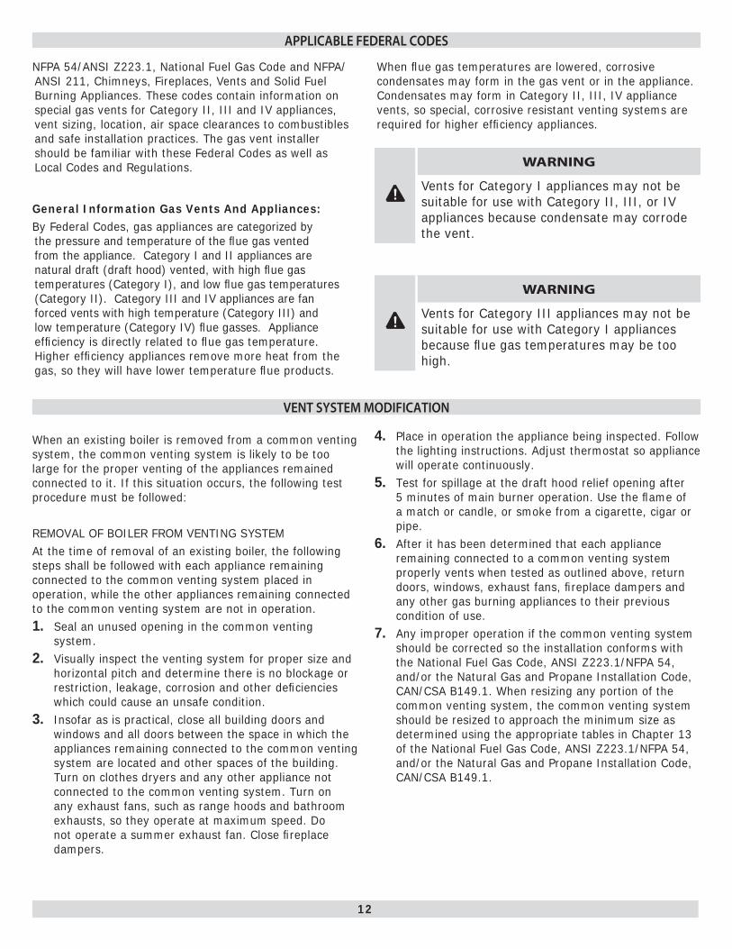
When an existing boiler is removed from a common venting system, the common venting system is likely to be too large for the proper venting of the appliances remained connected to it. If this situation occurs, the following test procedure must be followed:
REMOVAL OF BOILER FROM VENTING SYSTEMAt the time of removal of an existing boiler, the following steps shall be followed with each appliance remaining connected to the common venting system placed in operation, while the other appliances remaining connected to the common venting system are not in operation.
Seal an unused opening in the common venting 1. system.Visually inspect the venting system for proper size and 2. horizontal pitch and determine there is no blockage or restriction, leakage, corrosion and other defi ciencies which could cause an unsafe condition.Insofar as is practical, close all building doors and 3. windows and all doors between the space in which the appliances remaining connected to the common venting system are located and other spaces of the building. Turn on clothes dryers and any other appliance not connected to the common venting system. Turn on any exhaust fans, such as range hoods and bathroom exhausts, so they operate at maximum speed. Do not operate a summer exhaust fan. Close fi replace dampers.
Place in operation the appliance being inspected. Follow 4. the lighting instructions. Adjust thermostat so appliance will operate continuously.Test for spillage at the draft hood relief opening after 5. 5 minutes of main burner operation. Use the fl ame of a match or candle, or smoke from a cigarette, cigar or pipe.After it has been determined that each appliance 6. remaining connected to a common venting system properly vents when tested as outlined above, return doors, windows, exhaust fans, fi replace dampers and any other gas burning appliances to their previous condition of use.Any improper operation if the common venting system 7. should be corrected so the installation conforms with the National Fuel Gas Code, ANSI Z223.1/NFPA 54, and/or the Natural Gas and Propane Installation Code, CAN/CSA B149.1. When resizing any portion of the common venting system, the common venting system should be resized to approach the minimum size as determined using the appropriate tables in Chapter 13 of the National Fuel Gas Code, ANSI Z223.1/NFPA 54, and/or the Natural Gas and Propane Installation Code, CAN/CSA B149.1.
NFPA 54/ANSI Z223.1, National Fuel Gas Code and NFPA/ANSI 211, Chimneys, Fireplaces, Vents and Solid Fuel Burning Appliances. These codes contain information on special gas vents for Category II, III and IV appliances, vent sizing, location, air space clearances to combustibles and safe installation practices. The gas vent installer should be familiar with these Federal Codes as well as Local Codes and Regulations.
General Information Gas Vents And Appliances:By Federal Codes, gas appliances are categorized by the pressure and temperature of the fl ue gas vented from the appliance. Category I and II appliances are natural draft (draft hood) vented, with high fl ue gas temperatures (Category I), and low fl ue gas temperatures (Category II). Category III and IV appliances are fan forced vents with high temperature (Category III) and low temperature (Category IV) fl ue gasses. Appliance effi ciency is directly related to fl ue gas temperature. Higher effi ciency appliances remove more heat from the gas, so they will have lower temperature fl ue products.
When fl ue gas temperatures are lowered, corrosive condensates may form in the gas vent or in the appliance. Condensates may form in Category II, III, IV appliance vents, so special, corrosive resistant venting systems are required for higher effi ciency appliances.
APPLICABLE FEDERAL CODES
!
WARNING
Vents for Category I appliances may not be suitable for use with Category II, III, or IV appliances because condensate may corrode the vent.
!
WARNING
Vents for Category III appliances may not be suitable for use with Category I appliances because fl ue gas temperatures may be too high.
VENT SYSTEM MODIFICATION
13
HORIZONTAL VENT PIPE INSTALLATION INSTRUCTIONS
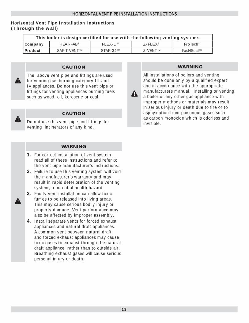
Horizontal Vent Pipe Installation Instructions (Through the wall)
This boiler is design certifi ed for use with the following venting systemsCompany HEAT-FAB® FLEX-L ® Z-FLEX® ProTech®
Product SAF-T-VENT™ STAR-34™ Z-VENT™ FasNSeal™
!
CAUTION
The above vent pipe and fi ttings are used for venting gas burning category III and IV appliances. Do not use this vent pipe or fi ttings for venting appliances burning fuels such as wood, oil, kerosene or coal.
! CAUTION
Do not use this vent pipe and fi ttings for venting incinerators of any kind.
!
WARNING
For correct installation of vent system, 1. read all of these instructions and refer to the vent pipe manufacturer's instructions.Failure to use this venting system will void 2. the manufacturer’s warranty and may result in rapid deterioration of the venting system, a potential health hazard.Faulty vent installation can allow toxic 3. fumes to be released into living areas. This may cause serious bodily injury or property damage. Vent performance may also be affected by improper assembly.Install separate vents for forced exhaust 4. appliances and natural draft appliances. A common vent between natural draft and forced exhaust appliances may cause toxic gases to exhaust through the natural draft appliance rather than to outside air. Breathing exhaust gases will cause serious personal injury or death.
!
WARNING
All installations of boilers and venting should be done only by a qualifi ed expert and in accordance with the appropriate manufacturers manual. Installing or venting a boiler or any other gas appliance with improper methods or materials may result in serious injury or death due to fi re or to asphyxiation from poisonous gases such as carbon monoxide which is odorless and invisible.
14
HORIZONTAL VENT INSTALLATION INSTRUCTIONS
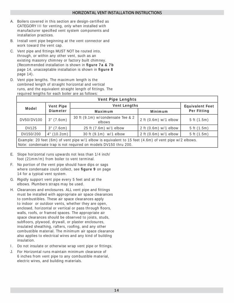
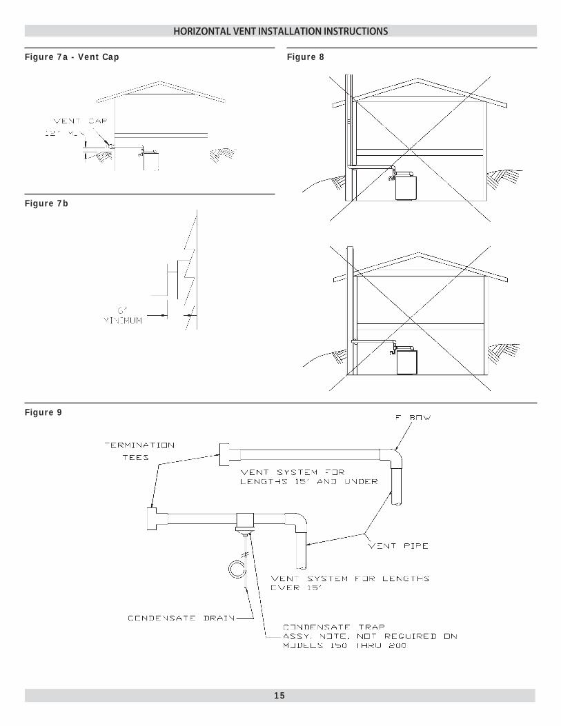
BA. oilers covered in this section are design-certifi ed as CATEGORY III for venting, only when installed with manufacturer specifi ed vent system components and installation practices.Install vent pipe beginning at the vent connector and B. work toward the vent cap.Vent pipe and fi ttings MUST NOT be routed into, C. through, or within any other vent, such as an existing masonry chimney or factory built chimney. (Recommended installation is shown in fi gure 7a & 7b page 14, unacceptable installation is shown in fi gure 8 page 14).Vent pipe lengths. The maximum length is the D. combined length of straight horizontal and vertical runs, and the equivalent straight length of fi ttings. The required lengths for each boiler are as follows:
Vent Pipe Lenghts
Model Vent Pipe Diameter
Vent Lengths Equivalent Feet Per FittingMaximum Minimum
DV50/DV100 3" (7.6cm) 30 ft (9.1m) w/condensate Tee & 2 elbows 2 ft (0.6m) w/1 elbow 5 ft (1.5m)
DV125 3" (7.6cm) 25 ft (7.6m) w/1 elbow 2 ft (0.6m) w/1 elbow 5 ft (1.5m)
DV150/200 4" (10.2cm) 30 ft (9.1m) w/1 elbow 2 ft (0.6m) w/1 elbow 5 ft (1.5m)
Example: 20 feet (6m) of vent pipe w/1 elbow is equivalent to 15 feet (4.6m) of vent pipe w/2 elbows. Note: condensate trap is not required on models DV150 thru 200.
E. Slope horizontal runs upwards not less than 1/4 inch/foot (21mm/m) from boiler to vent terminal.
F. No portion of the vent pipe should have dips or sags where condensate could collect, see fi gure 9 on page 14 for a typical vent system.
G. Rigidly support vent pipe every 5 feet and at the elbows. Plumbers straps may be used.
H. Clearances and enclosures. ALL vent pipe and fi ttings must be installed with appropriate air space clearances to combustibles. These air space clearances apply to indoor or outdoor vents, whether they are open, enclosed, horizontal or vertical or pass through fl oors, walls, roofs, or framed spaces. The appropriate air space clearances should be observed to joists, studs, subfl oors, plywood, drywall, or plaster enclosures, insulated sheathing, rafters, roofi ng, and any other combustible material. The minimum air space clearance also applies to electrical wires and any kind of building insulation.
I. Do not insulate or otherwise wrap vent pipe or fi ttings.J. For Horizontal runs maintain minimum clearance of
6 inches from vent pipe to any combustible material, electric wires, and building materials.
15
HORIZONTAL VENT INSTALLATION INSTRUCTIONS
Figure 9
Figure 7a - Vent Cap
Figure 7b
Figure 8

16
Figure 10 - Typical Installation
Notes: Condensate tee/drain is only needed when horizontal vent lengths exceed 10 feet (3m).1. Insert vent pipe in boiler venter outlet (vent adapter), apply silicone completely around edge of outlet and tighten 2. clamp.
HORIZONTAL VENT INSTALLATION INSTRUCTIONS
17
HORIZONTAL VENT INSTALLATION INSTRUCTIONS
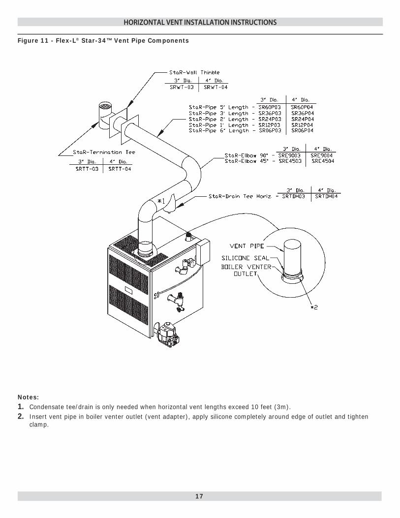
Notes: Condensate tee/drain is only needed when horizontal vent lengths exceed 10 feet (3m).1. Insert vent pipe in boiler venter outlet (vent adapter), apply silicone completely around edge of outlet and tighten 2. clamp.
Figure 11 - Flex-L® Star-34™ Vent Pipe Components
18
HORIZONTAL VENT INSTALLATION INSTRUCTIONS
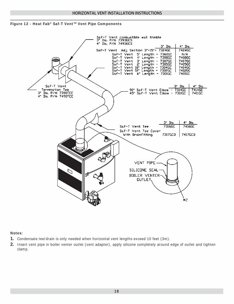
Figure 12 - Heat Fab® Saf-T Vent™ Vent Pipe Components
Notes: Condensate tee/drain is only needed when horizontal vent lengths exceed 10 feet (3m).1. Insert vent pipe in boiler venter outlet (vent adapter), apply silicone completely around edge of outlet and tighten 2. clamp.
19
HORIZONTAL VENT INSTALLATION INSTRUCTIONS
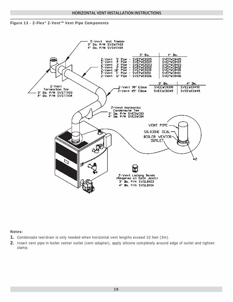
Figure 13 - Z-Flex® Z-Vent™ Vent Pipe Components
Notes: Condensate tee/drain is only needed when horizontal vent lengths exceed 10 feet (3m).1. Insert vent pipe in boiler venter outlet (vent adapter), apply silicone completely around edge of outlet and tighten 2. clamp.

20
HORIZONTAL VENT INSTALLATION INSTRUCTIONS
Notes: Condensate tee/drain is only needed when horizontal vent lengths exceed 10 feet (3m).1. Insert vent pipe in boiler venter outlet (vent adapter), apply silicone completely around edge of outlet and tighten 2. clamp.
Figure 14 - ProTech® FasNSeal™ Vent Pipe Components
21
HORIZONTAL VENT INSTALLATION INSTRUCTIONS
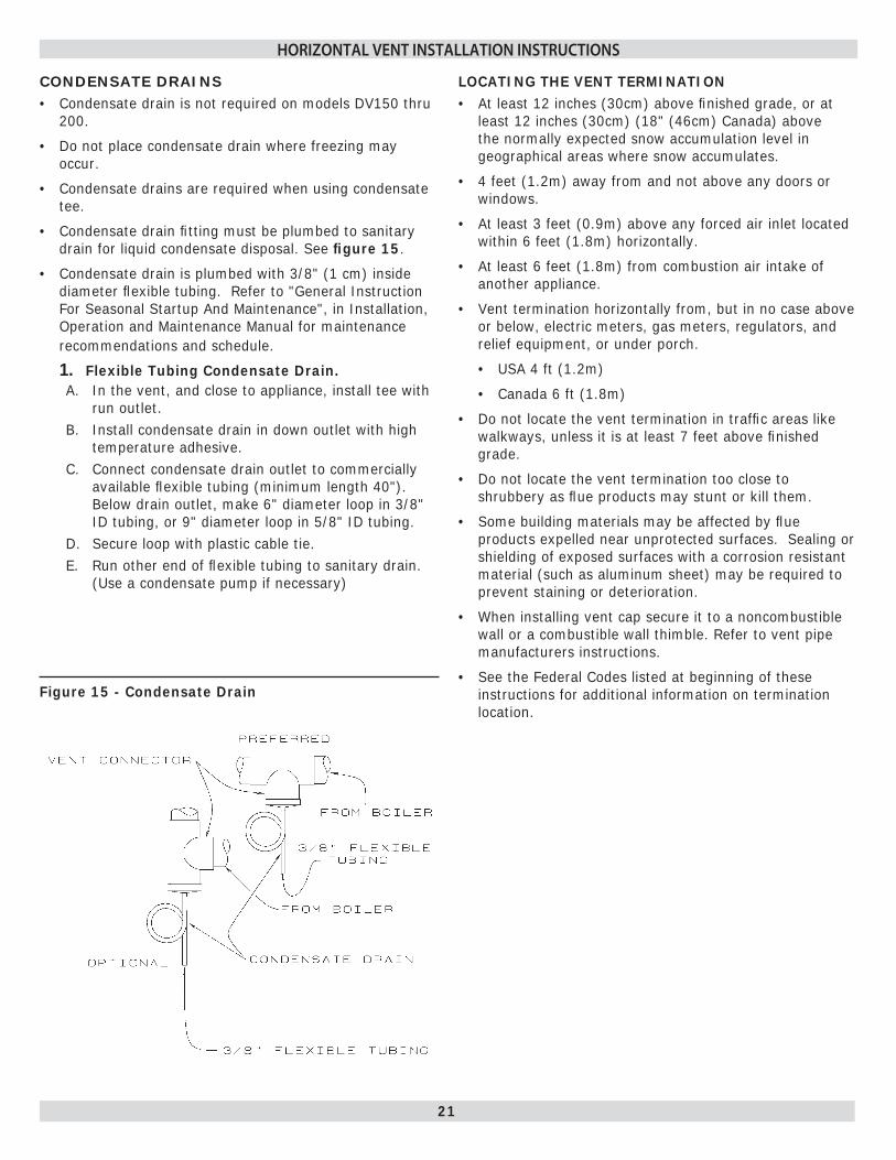
CONDENSATE DRAINSC• ondensate drain is not required on models DV150 thru 200.
Do not place condensate drain where freezing may • occur.
Condensate drains are required when using condensate • tee.
Condensate drain fi tting must be plumbed to sanitary • drain for liquid condensate disposal. See fi gure 15.
Condensate drain is plumbed with 3/8" (1 cm) inside • diameter fl exible tubing. Refer to "General Instruction For Seasonal Startup And Maintenance", in Installation, Operation and Maintenance Manual for maintenance recommendations and schedule.
Flexible Tubing Condensate Drain.1. In the vent, and close to appliance, install tee with A. run outlet. Install condensate drain in down outlet with high B. temperature adhesive. Connect condensate drain outlet to commercially C. available fl exible tubing (minimum length 40"). Below drain outlet, make 6" diameter loop in 3/8" ID tubing, or 9" diameter loop in 5/8" ID tubing. Secure loop with plastic cable tie. D. Run other end of fl exible tubing to sanitary drain. E. (Use a condensate pump if necessary)
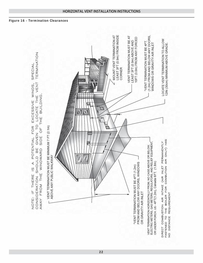
LOCATING THE VENT TERMINATIONAt least 12 inches (30cm) above fi nished grade, or at • least 12 inches (30cm) (18" (46cm) Canada) above the normally expected snow accumulation level in geographical areas where snow accumulates.
4 feet (1.2m) away from and not above any doors or • windows.
At least 3 feet (0.9m) above any forced air inlet located • within 6 feet (1.8m) horizontally.
At least 6 feet (1.8m) from combustion air intake of • another appliance.
Vent termination horizontally from, but in no case above • or below, electric meters, gas meters, regulators, and relief equipment, or under porch.
USA 4 ft (1.2m)•
Canada 6 ft (1.8m)•
Do not locate the vent termination in traffi c areas like • walkways, unless it is at least 7 feet above fi nished grade.
Do not locate the vent termination too close to • shrubbery as fl ue products may stunt or kill them.
Some building materials may be affected by fl ue • products expelled near unprotected surfaces. Sealing or shielding of exposed surfaces with a corrosion resistant material (such as aluminum sheet) may be required to prevent staining or deterioration.
When installing vent cap secure it to a noncombustible • wall or a combustible wall thimble. Refer to vent pipe manufacturers instructions.
See the Federal Codes listed at beginning of these • instructions for additional information on termination location.
Figure 15 - Condensate Drain
22
HORIZONTAL VENT INSTALLATION INSTRUCTIONS
Figure 16 - Termination Clearances

23
VERTICAL VENT PIPE INSTALLATION INSTRUCTIONS
PROVIDING FOR PROPER VENTING THROUGH THE ROOF
Vent boiler making Ref. to NFGC section 2 & 10 and • using these instructions and requirements of local utilities and other local code authorities.
You must connect boiler to vent or factory-built • chimney. Vent or factory-built chimney must meet recognized standard.
Chimney lining method and material must comply with • local code requirements.
Use corrosion-resistant material meeting nationally • recognized standards for vent construction.
! WARNING
Inadequate vent or chimney could allow combustion products to collect in structure, resulting in injury or death.
!
WARNING
Vent this boiler separately from any appliance designed to burn solid fuel, particularly wood burning or coal burning appliances. Improper venting could allow combustion products to collect in the structure, resulting in injury or death.
A. VENTING CATEGORYBoilers covered by this manual are design-certifi ed • as CATEGORY I for venting. CATEGORY I Appliances have non-positive vent static pressure and rely on heat content of combustion products to vent. You may common vent CATEGORY I boilers.
Boilers covered by this manual are also design • certifi ed as CATEGORY III for venting, only when they installed with manufacturer specifi ed vent system components and installed practices. Ref. pages 12-21 for category 3 venting instructions.
B. DESIGN CONSIDERATIONSAvoid oversizing boiler for your application. Select a • boiler model with a rated heating output close to the calculated heating load. This extends the fi ring period, decreasing the potential for condensate formation in the vent.
Too small a vent cannot carry all combustion products • outdoors. Too large a vent will not vent combustion products rapidly enough to avoid potential for condensation. Refer to pages 24 thru 27 for correct vent size.
Vent height must be a minimum of six feet. Minimize • vent connector horizontal runs to the extent possible for best performance.
The designer must consider the building’s orientation, • answering these questions. (Ref. pages 24-27).
Will the vent terminate outside the building where A. its operation could be adversely affected by winds?Could any adjacent buildings adversely affect vent B. operation? Allowing for these factors can reduce the C. possibility of downdraft conditions.
If your local experience indicates possible condensation • problems, provide for draining and disposal of venting system condensate.
C. VENT SIZINGSometimes horizontal distance from boiler to vent or • chimney is already given; this is known as horizontal vent connector run. Vent or chimney height is also usually given as Btuh input of gas appliances served by vent.
Check these parameters to be sure venting system will • work. Use approved engineering practices and part 7 & 10 of the latest revision of the (NFGC) National Fuel Gas Code, ANSI Z233.1/NFPA54.
Use this venting addendum for single appliance venting • and multiple appliance (common) venting. For multi story installations, refer to latest revision of National Fuel Gas Code ANSI Z223.1/NFPA 54.
D. VENT CONNECTORVent connectors must be made of noncombustible, • corrosion resistant material capable of withstanding vent gas temperatures. They must be thick enough to withstand physical damage and be accessible for inspection, cleaning and replacement.
Use Type B 1 vent connector in or through attics, crawl • spaces, or other cold areas. Install thimbles that meet local codes when vent connectors pass through walls or partitions of combustible material.
Keep vent connectors as short as possible by locating • boiler as close as practical to vent or chimney. Avoid unnecessary turns or bends which create resistance to fl ow of vent gases. Adding an elbow adds resistance. For example, adding a 6" 90-degree elbow would be the equivalent of adding 20 feet of horizontal 6" pipe. (45-degree elbows have lower resistance than 90-degree elbows, and can work for most vent runs).
If you join two or more vent connectors before they • enter vertical vent or chimney, see fi gure 17, on page 24. Also refer to NFGC book, ANSI standards and NFPA book.

24
VERTICAL VENT PIPE INSTALLATION INSTRUCTIONS
Do not connect boiler to any portion of vent system • which operates under positive pressure. Positive pressure will result with CATEGORY III or IV appliances connected to vent.
Do not connect vent connector to chimney fl ue serving a • fi replace.
E. VERTICAL VENT OR CHIMNEYVents and chimneys usually extend vertically with • offsets not exceeding 45-degrees. Consider vent pipe runs more than 45-degrees as horizontal runs. Include their length in total horizontal run.
Designer and installer must provide appropriately sized • common vent for all appliances connected to it. (Ref. to fi gure 17, on page 17 or the latest revision of the NFGC)
Connect this CATEGORY I boiler only to vent systems • with other CATEGORY I appliances.
!
WARNING
Do not connect CATEGORY I boiler to vent system used by CATEGORY III and IV appliance. Do not connect it to vents with mechanical draft systems operating at positive pressure. Improper venting could allow combustion products to collect in structure during use, resulting in damage, injury or death.
F. CHIMNEY LININGUse suitably sized Type B1 vent liner or suitable • corrigated liner. See fi gure 17 page 24.
!
WARNING
Support vent liner in masonry chimney. Maintain at least 1" clearance on all sides to reduce possibility of condensate in vent. Condensate may cause vent to deteriorate allowing combustion products to collect in structure, which could result in injury or death. See fi gure 17 page 24.
!
WARNING
Vent liner must not block opening where other appliance's vent connectors enter chimney. Blocked openings will cause combustion products to collect in structure, resulting in damage, injury or death.
!
WARNING
Do not use unlined masonry chimneys. These increase risk of condensate formation, which may cause chimney to deteriorate, allowing combustion products to collect in structure, resulting in damage, injury or death.
G. VENT TERMINATIONTerminate all vertical vents with a listed vent cap or roof • assembly unless local codes require otherwise.
See vent cap or roof assembly manufacturer’s • instructions.
Locate vent termination (vent cap or roof assembly) in • an area without positive pressures or eddy currents. Eddy currents occur when air swirls over roof peaks. They cause down-drafts and adversely affect vent operation. See fi gure 19 page 24.
Some vent terminations or caps protect against eddy • currents and down-drafts. Consult their manufacturer’s instructions.
Vent terminations or caps should usually be at least • the same size as the vent. They may be larger if the installation warrants.
Vent systems must end at least fi ve feet above the • highest gas appliance connection.
Vent pipe must extend at least three feet above the • point where it passes through the roof.
Vent termination must be at least two feet higher than • any portion of building within ten feet horizontal and vent termination must be at least two feet higher than roof peaks within ten feet horizontal. See fi gures 20 and 21 page 24 .
Some vent cap manufacturers offer vent caps that allow • reduced clearances. Consult their instructions.
!
WARNING
Failure to properly terminate vent chimney systems could allow combustion products to collect in structure, resulting in injury or death.
Terminate venting system at least three feet above any • forced-air building inlet within ten feet. Consider doors, windows and gravity air building inlets. Locate vent termination at least four feet below, four horizontal feet from or one foot above any of these openings.

25
VERTICAL VENT PIPE INSTALLATION INSTRUCTIONS
Figure 17 - Vent Liner
Figure 18 - Vent Liner Support In Masonry Chimney
Figure 19 - Avoid areas of Wind Currents
Figure 20 - Termination 10 ft (3m) Or Less From Ridge
Figure 21 - Termination More Than 10 Ft (3m) From Ridge
Table 4 Roof Pitch Chart
Roof Pitch Height Above Roof Brace
Flat to 7/12 1.0 ft (0.3m)
Over 7/12 to 8/12 1.5 ft (0.5m)
Over 8/12 to 9/12 2.0 ft (0.6m)
Over 9/12 to 10/12 2.5 ft (0.8m)Brace to Roof
at topOver 10/12 to 11/12 3.3 ft (1.0m)
Over 11/12 to 12/12 4.0 ft (1.2m)
Over 12/12 to 14/12 5.0 ft (1.5m)
Brace to Roof at Top and Mid Point
Over 14/12 to 16/12 6.0 ft (1.8m)
Over 16/12 to 18/12 7.0 ft (2.1m)
Over 18/12 to 8/12 7.5 ft (2.3m)
Over 20/12 to 21/12 8.0 ft (2.4m)

26
VERTICAL VENT PIPE INSTALLATION INSTRUCTIONS
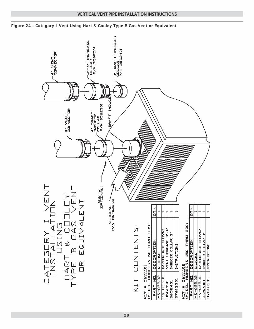
H. INSTALLATIONVent Adaptor.•
Attach vent adaptor at draft inducer collar. See A. fi gure 24 on page 27. Use Kit # 56111101 for DV 50-125 and Kit # 56111102 for DV 150-200, or equivalent.
!
WARNING
Make sure that all vent pipe and connectors are secured because unsecured vent pipe connections may loosen. This can allow combustion products to collect in the structure, resulting in injury or death.
Vent Connector.•
Install vent connectors without any dips or sags. A. Slope them upward from boiler at least 1/4" per foot. To prevent sagging, at each joint support vent connectors and horizontal portions using hangers, straps or equivalent. Seal all connections where vent connectors enter chimney. See fi gure 17 on page 24.
Vertical Vent.•
Install vent materials following their listing terms, A. manufacturer’s instructions, these instructions and local codes. A gas vent passing through a roof must extend through roof fl ashing, jack or thimble. It must terminate above the roof surface. See fi gures 20 & 21.
I. EXISTING VENT CONSIDERATIONSMasonry chimneys previously used for venting equipment should be suitably per NFGC standard. Also provide an accessible clean out per the latest revision of the NFGC, ANSI Z2231, AND NFPA 54.1
Vent Inspection1. Make sure existing vent or chimney is the proper A. size and construction for appliances that will use it. The best way to do this is to size as if it were a new installation. Compare the existing vent to your calculations and make necessary corrections.Examine vent or chimney cleanouts to make sure B. they remain tightly closed when not in use. Make sure vent or chimney passageway is clear and free of obstructions. Look for evidence of condensate or deterioration in vent or chimney. Either of these means an inadequate vent.If you fi nd an inadequate vent or chimney, do not C. leave it as is. Repair or replace it. A new vent must meet these instructions and the latest revision of the National Fuel Gas Code ANSI Z223.1/NFPA 54.
MODEL D1 D2 D2 MIN MAX DV50 4" 4" 5" DV100 4" 4" 6" DV125 4" 4" 8" DV150 - 200 4" 5" 8"
NOTE: See below*
*Information contained in this fi gure is only one of many possible vertical venting confi gurations. Follow appropriate sections of NFGC for proper venting practice for category 1 appliances.
Figure 22 - Vertical Venting Installation for Type B Vent*
27
VERTICAL VENT PIPE INSTALLATION INSTRUCTIONS
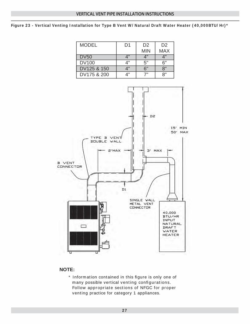
Figure 23 - Vertical Venting Installation for Type B Vent W/Natural Draft Water Heater (40,000BTU/Hr)*
MODEL D1 D2 D2 MIN MAX DV50 4" 4" 4" DV100 4" 5" 6" DV125 & 150 4" 6" 8" DV175 & 200 4" 7" 8"
NOTE: NOTE: * Information contained in this fi gure is only one of nformation contained in this fi gure is only one of
many possible verticalmany possible vertical venting confi gurations. venting confi gurations. Follow appropriate sections of NFGC for proper Follow appropriate sections of NFGC for proper ventingventing practice for category 1 appliances. practice for category 1 appliances.
28
Figure 24 - Category I Vent Using Hart & Cooley Type B Gas Vent or Equivalent
VERTICAL VENT PIPE INSTALLATION INSTRUCTIONS
29
CONNECTING GAS SERVICE
GeneralUse piping materials and joining methods acceptable • to authority having jurisdiction. In absence of such requirements:
USA - National Fuel gas Code, ANSI Z223.1/NFPA 54• Canada - Natural Gas and Propane Installation Code, • CAN/CSA B149.1
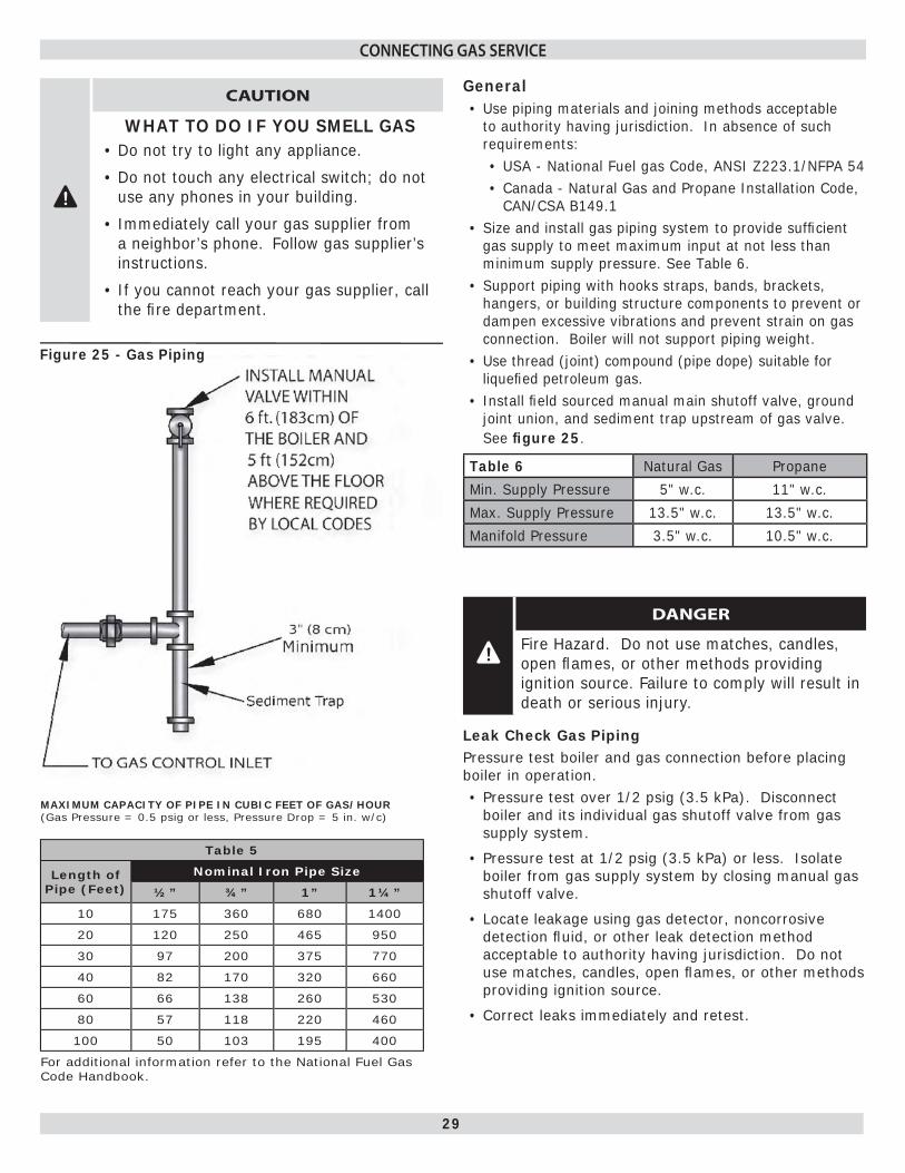
Size and install gas piping system to provide suffi cient • gas supply to meet maximum input at not less than minimum supply pressure. See Table 6.Support piping with hooks straps, bands, brackets, • hangers, or building structure components to prevent or dampen excessive vibrations and prevent strain on gas connection. Boiler will not support piping weight.Use thread (joint) compound (pipe dope) suitable for • liquefi ed petroleum gas.Install fi eld sourced manual main shutoff valve, ground • joint union, and sediment trap upstream of gas valve. See fi gure 25.
Table 6 Natural Gas Propane
Min. Supply Pressure 5" w.c. 11" w.c.
Max. Supply Pressure 13.5" w.c. 13.5" w.c.
Manifold Pressure 3.5" w.c. 10.5" w.c.
!
DANGER
Fire Hazard. Do not use matches, candles, open fl ames, or other methods providing ignition source. Failure to comply will result in death or serious injury.
Leak Check Gas PipingPressure test boiler and gas connection before placing boiler in operation.
Pressure test over 1/2 psig (3.5 kPa). Disconnect • boiler and its individual gas shutoff valve from gas supply system.
Pressure test at 1/2 psig (3.5 kPa) or less. Isolate • boiler from gas supply system by closing manual gas shutoff valve.
Locate leakage using gas detector, noncorrosive • detection fl uid, or other leak detection method acceptable to authority having jurisdiction. Do not use matches, candles, open fl ames, or other methods providing ignition source.
Correct leaks immediately and retest.•
MAXIMUM CAPACITY OF PIPE IN CUBIC FEET OF GAS/HOUR(Gas Pressure = 0.5 psig or less, Pressure Drop = 5 in. w/c)
Table 5
Length of Pipe (Feet)
Nominal Iron Pipe Size
½” ¾” 1” 1¼”
10 175 360 680 1400
20 120 250 465 950
30 97 200 375 770
40 82 170 320 660
60 66 138 260 530
80 57 118 220 460
100 50 103 195 400
For additional information refer to the National Fuel Gas Code Handbook.
Figure 25 - Gas Piping
!
CAUTION
WHAT TO DO IF YOU SMELL GASDo not try to light any appliance.•
Do not touch any electrical switch; do not • use any phones in your building.
Immediately call your gas supplier from • a neighbor’s phone. Follow gas supplier’s instructions.
If you cannot reach your gas supplier, call • the fi re department.

30
* Not all components listed are used in all control systems.
NOTES: * Switches are shown in position during the heating cycle.
* If any of the original wiring supplied with the boiler is replaced it must be replaced with like wire size and type of insulation or equivalent.
When installed boiler must be electrically bonded to • ground in accordance with the requirements of the authority having jurisdiction or, in the absence of such requirements, with the National Electrical code, ANSI/NFPA 70, and/or the Canadian Electrical Code Part 1, CSA C22.1, Electrical Code.
Install fused disconnect switch between boiler and meter • at convenient location.
Hot water control and intermittent ignition wiring for boilers with fail safe relay. See fi gure 26.
WIRING CODE KEY
LINE VOLTAGE BY FACTORY
LOW VOLTAGE BY FACTORY
LINE VOLTAGE BY INSTALLER
LOW VOLTAGE BY INSTALLER
COMPONENT KEY CODING
Thermostat (millivolt) TH-1
Thermostat (24 Volt) TH-2
Thermostat (Line Voltage) TH-3
Transformer (120V/24V 40VA) TR-1
Transformer (120V/24V 50VA) TR-2
24 Volt Gas Valve LGV
24 Volt Gas Valve LGV-1
Pressure Switch PS
Manual Reset Pressure Sw. MR-PS
Control Terminal
Relay Coil 1K
Relay Contacts 1K1
Relay Contacts 1K2
Limit Switch LS
Manual Switch MS
Circulator CIR
Energy Cut-Off ECO
Pilot Safety Coil PSC
Wire Connection
Low Water Cut Off LWCO
Electric Water Feeder EWF
Power Generator PG
Roll-Out Switch RSW
COMPONENT AND Wire CODING KeysThe keys that follow pertain to the HOT WATER CONTROL AND INTERMITTENT IGNITION WIRING diagrams.
ELECTRICAL WIRING

31
ELECTRICAL WIRING
Figure 26 - HOT WATER CONTROL AND INTERMITTENT IGNITION WIRING
32
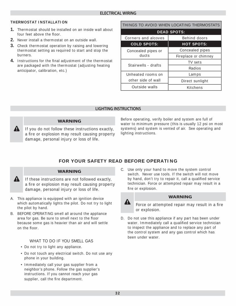
THERMOSTAT INSTALLATION
Thermostat should be installed on an inside wall about 1. four feet above the fl oor.Never install a thermostat on an outside wall.2. Check thermostat operation by raising and lowering 3. thermostat setting as required to start and stop the burners.Instructions for the fi nal adjustment of the thermostat 4. are packaged with the thermostat (adjusting heating anticipator, calibration, etc.)
THINGS TO AVOID WHEN LOCATING THERMOSTATS
DEAD SPOTS:
Corners and alcoves Behind doors
COLD SPOTS: HOT SPOTS:
Concealed pipes or ducts
Concealed pipes
Fireplace or chimney
Stairwells - draftsTV sets
Radios
Unheated rooms onother side of wall
Lamps
Direct sunlight
Outside walls Kitchens
This appliance is equipped with an ignition device A. which automatically lights the pilot. Do not try to light the pilot by hand.BEFORE OPERATING smell all around the appliance B. area for gas. Be sure to smell next to the fl oor because some gas is heavier than air and will settle on the fl oor.
WHAT TO DO IF YOU SMELL GASDo not try to light any appliance.•
Do not touch any electrical switch. • Do not use any phone in your building.
Immediately call your gas supplier from a • neighbor’s phone. Follow the gas supplier’s instructions. If you cannot reach your gas supplier, call the fi re department.
Use only your hand to move the system control C. switch. Never use tools. If the switch will not move by hand, don’t try to repair it, call a qualifi ed service technician. Force or attempted repair may result in a fi re or explosion.
! WARNING
Force or attempted repair may result in a fi re or explosion.
Do not use this appliance if any part has been under D. water. Immediately call a qualifi ed service technician to inspect the appliance and to replace any part of the control system and any gas control which has been under water.
LIGHTING INSTRUCTIONS
ELECTRICAL WIRING
! WARNING
If you do not follow these instructions exactly, a fi re or explosion may result causing property damage, personal injury or loss of life.
Before operating, verify boiler and system are full of water to minimum pressure (this is usually 12 psi on most systems) and system is vented of air. See operating and lighting instructions.
FOR YOUR SAFETY READ BEFORE OPERATING
! WARNING
If these instructions are not followed exactly, a fi re or explosion may result causing property damage, personal injury or loss of life.

33
LIGHTING PROCEDURE FOR BOILER WITH
INTERMITTENT PILOT SYSTEM
STOP!1. Read the safety information in the user’s infor-mation manual.Set thermostat to lowest setting.2. Turn off all electric power to the appliance.3. This appliance is equipped with an ignition device which 4. automatically lights the burner. DO NOT try to light the burner by hand.Turn the gas control knob clockwise 5. to “OFF”. See fi gure 27.Wait fi ve (5) minutes to clear out any gas. Then smell 6. for gas, including near the fl oor. If you smell gas, STOP! Follow “What To Do If You Smell Gas” in the safety information section. If you don’t smell gas, go on to the next step.Turn the gas control knob counterclockwise 7. to “ON”.Turn on all electrical power to the appliance.8. Set the thermostat to desired setting.9. If the appliance will not operate, follow the instructions 10. “To Turn Off Gas To Appliance” and call your service technician or gas supplier.
TO TURN OFF GAS TO APPLIANCESet the thermostat to lowest setting.1. Turn off all electric power to the appliance if service is 2. to be preformed.
Turn gas control knob clockwise 3. to “OFF” Do Not Force.
On a call for heat:The thermostat will actuate, completing the circuit 1. between terminals T and T.The R8222C relay coil will energize thus pulling in the 2. relay contacts.The circulator starts and power is switched to the limit. 3. If limit circuit is closed the venter motor and TF-2 transformer are energized.The venter motor starts and develops static pressure.4. When the static pressure is reached the pressure switch 5. pulls in completing the circuit between TF-2 and the intermittent ignition control.The intermittent ignition control opens the pilot valve 6. and ignites pilot. After pilot is proven the main burner will ignite.In the event the boiler water temperature exceeds the 7. high limit setting the power will be interrupted to the venter motor, and TF-2 thus interrupting power to the ignition system. Power will remain off until the water temperature drops below the high limit setting. The circulator will continue to operate under this condition until the thermostat is satisfi ed.
Should the air fl ow (static pressure) be interrupted 8. (example blocked fl ue, etc.), the pressure switch will sense a drop in pressure, opening the circuit between the ignition system and TF-2. The venter motor will continue to operate until static pressure is reached or thermostat is satisfi ed.In the event the fl ow of combustion products through 9. any part of the boiler fl ueway becomes blocked, a fl ame safety roll-out switch will shut off the main burners. If this condition occurs, do not attempt to place the boiler back operation.When the thermostat is satisfi ed power is interrupted to 10. the relay coil and the relay drops out cutting power to the circulator, venter motor, and TF-2.
LIGHTING INSTRUCTIONS
Figure 27 - Intermittent Pilot System
SEQUENCE OF OPERATION
34
It is suggested that a qualifi ed service agency be employed to make an annual inspection of the boiler and the heating system. They are experienced in making the inspection outlined below.In the event repairs or corrections are necessary they can make the proper changes for safe operation of the boiler.
! CAUTION
Label all wires prior to disconnection when servicing controls. Wiring errors can cause improper and dangerous operation.
Verify proper operation after service.If the venter has oil cups, lubricate venter motor once a month during the heating season with a few drops of non-detergent motor oil (SAE 20 or 30). Replace the rubber plugs when fi nished.
! CAUTION
Do not over oil.
BEGINNING OF EACH HEATING SEASONBefore seasonal start-up, it is highly advisable to have 1. a certifi ed service agency inspect the system:
Check the boiler for soot and scale build up in the A. fl ues. Clean the burners.B. Check the gas input rate to maintain high operating C. effi ciency.
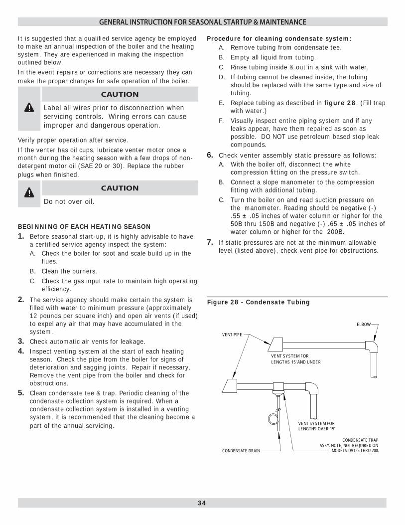
The service agency should make certain the system is 2. fi lled with water to minimum pressure (approximately 12 pounds per square inch) and open air vents (if used) to expel any air that may have accumulated in the system.Check automatic air vents for leakage.3. Inspect venting system at the start of each heating 4. season. Check the pipe from the boiler for signs of deterioration and sagging joints. Repair if necessary. Remove the vent pipe from the boiler and check for obstructions.Clean condensate tee & trap. Periodic cleaning of the 5. condensate collection system is required. When a condensate collection system is installed in a venting system, it is recommended that the cleaning become a part of the annual servicing.
VENT PIPE
ELBOW
VENT SYSTEM FORLENGTHS 15' AND UNDER
VENT SYSTEM FOR LENGTHS OVER 15'
CONDENSATE TRAPASSY. NOTE, NOT REQUIRED ON
MODELS DV125 THRU 200.CONDENSATE DRAIN
Procedure for cleaning condensate system:Remove tubing from condensate tee.A. Empty all liquid from tubing.B. Rinse tubing inside & out in a sink with water.C. If tubing cannot be cleaned inside, the tubing D. should be replaced with the same type and size of tubing.Replace tubing as described inE. fi gure 28. (Fill trap with water.)Visually inspect entire piping system and if any F. leaks appear, have them repaired as soon as possible. DO NOT use petroleum based stop leak compounds.
Check venter assembly static pressure as follows:6. With the boiler off, disconnect the white A. compression fi tting on the pressure switch.Connect a slope manometer to the compression B. fi tting with additional tubing.Turn the boiler on and read suction pressure on C. the manometer. Reading should be negative (-) .55 ± .05 inches of water column or higher for the 50B thru 150B and negative (-) .65 ± .05 inches of water column or higher for the 200B.
If static pressures are not at the minimum allowable 7. level (listed above), check vent pipe for obstructions.
GENERAL INSTRUCTION FOR SEASONAL STARTUP & MAINTENANCE
Figure 28 - Condensate Tubing

35
The following procedure should be followed to clean 8. and check the boiler fl ue passageways:
Remove the burners from the combustion chamber A. by raising the burners up from the manifold orifi ces and pulling toward the front of the boiler. See fi gure 29.Disconnect the vent pipe from the vent adapter.B. Remove the top jacket panel. See C. figure 30.Disconnect the white compression fi tting from the D. pressure switch.Disconnect venter wires from relay.E. Remove the fl ue collector and venter from the F. boiler castings by loosening the hold-down bolts located on each side of the collector. See fi gure 31. Visually inspect the venter assembly for any G. unusual wear or dirt build up. Clean with vacuum if necessary.Place a sheet of heavy paper or similar material H. over the bottom of the combustion chamber and brush down the fl ue passageways. The soot and scale will collect on the paper and is easily removed with the paper.Vacuum out base and fl ueways and reassemble the I. boiler in reverse order.Seal fl ue collector and vent adapter with high J. temperature silicone. (+400°)
Start boiler to ensure proper operating condition.K.
Keep the area around the boiler clean and free of 9. combustible materials such as gasoline, paints, paint thinner and other such fl ammable vapors and liquids.The free fl ow of combustion and ventilating air to 10. the boiler and boiler room must not be restricted or blocked.Some circulators require periodic servicing. These 11. circulators usually have oil cups or openings at each end of the motor and one for the shaft bearing. Put about one teaspoon of SAE 20 or 30 non-detergent motor oil in each opening twice per year. DO NOT OVER OIL. Follow the manufacturers instructions attached to the circulator. When oil cups or holes are not provided, bearings are either permanently lubricated or water lubricated.Visually check the main burners and pilot fl ame at the 12. start of each heating season and again midway through the season.
Check the burner throats and burner orifi ces for lint A. and dust obstructions. See fi gure 31.The main burner fl ame should have a well defi ned B. inner blue mantel with a lighter blue outer mantel. See fi gure 32.
The pilot fl ame should envelop ⅜ to ½ inch of the C. tip of the pilot sensing device. See fi gure 33.
GENERAL INSTRUCTION FOR SEASONAL STARTUP & MAINTENANCE
COMBUSTION
BURNER
(REMOVED)
BURNERS GAS
VENT PIPE
CHAMBER
DOOR
VALVE
ADAPTER
ROLL-OUT SAFETY
BURNER
SWITCH
JACKET FRONT PANEL
BURNERS
ORIFICESGAS VALVE
HOLD DOWN BOLT
FLUE COLLECTOR
VENTER ASSEMBLY
Figure 30 - Top Jacket Panel
Figure 31 - Burners
(Location may vary by model)
Figure 29 - Combustion Chamber
BURNERS
ORIFICES
GAS VALVE

36
Th e main burner fl ame should form a sharp blue inner mantel with no yellow.
Adjusting the pilot fl ame:13. Remove the pilot adjustment cover screw.A.
Turn inner screw (adjustment screw) clockwiseB. to decrease and counterclockwise to increase the pilot fl ame. See fi gure 34.After adjustment, be sure to replace cover screw to C. prevent possible gas leakage.The main burners and the pilot burner should be D. checked for signs of corrosion or scale build up.Clean main burners and pilot burner with a steel E. bristle brush.
CHECK GAS INPUT RATE TO BOILERMaximum permissible gas supply pressure must not 1. be higher and minimum supply pressure must not be lower than what is specifi ed on the rating plate.To check for proper fl ow of natural gas to boiler using 2. the gas meter, proceed as follows:
Turn off the gas supply to all other appliances, A. except the boiler.With the boiler operating, determine the fl ow of gas B. through the meter for two minutes and multiply by 30 to get the hourly rate (in cubic feet).Divide the input rate shown on the rating plate by C. the heating value of the gas as obtained from the local gas company. This will determine the number of cubic feet of gas required per hour.If minor adjustment is necessary, adjust the D. pressure regulator on the combination gas control. Increase or decrease manifold pressure to obtain gas input required as described on the rating plate. To increase, turn the regulator adjusting screw clockwise or counterclockwise to decrease pressure, see fi gure 38. The manifold pressures are taken at the outlet side of the gas valve.Relight all the other appliances turned off in step E. "a." above. Be sure all pilot burners are operating.
IGNITION ELECTRODE
3/8” TO 1/2”IN FLAME
GENERAL INSTRUCTION FOR SEASONAL STARTUP & MAINTENANCE
Figure 32 - Main Burner Flame
Figure 33 - Pilot Flame
Figure 34 - Gas VaLve
37
1
2
3
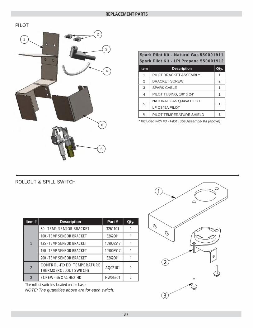
ROLLOUT & SPILL SWITCH
Item # Description Part # Qty.
1
50 - TEMP. SENSOR BRACKET 3261101 1
100 - TEMP SENSOR BRACKET 3262001 1
125 - TEMP SENSOR BRACKET 109008517 1
150 - TEMP SENSOR BRACKET 109008517 1
200 - TEMP SENSOR BRACKET 3262001 1
2 CONTROL-FIXED TEMPERATURE THERMO (ROLLOUT SWITCH) AQ02101 1
3 SCREW - #6 X ¼ HEX HD HW06501 2The rollout switch is located on the base.NOTE: The quantities above are for each switch.
PILOT
Spark Pilot Kit - Natural Gas 550001911Spark Pilot Kit - LP/Propane 550001912
Item Description Qty.
1 PILOT BRACKET ASSEMBLY 1
2 BRACKET SCREW 2
3 SPARK CABLE 1
4 PILOT TUBING, 1/8" x 24" 1
5NATURAL GAS Q345A PILOT
1LP Q345A PILOT
6 PILOT TEMPERATURE SHIELD 1
* Included with #3 - Pilot Tube Assembly Kit (above)
REPLACEMENT PARTS
1
6
4
2
3
5
38
1
2
3
4
5
6
7
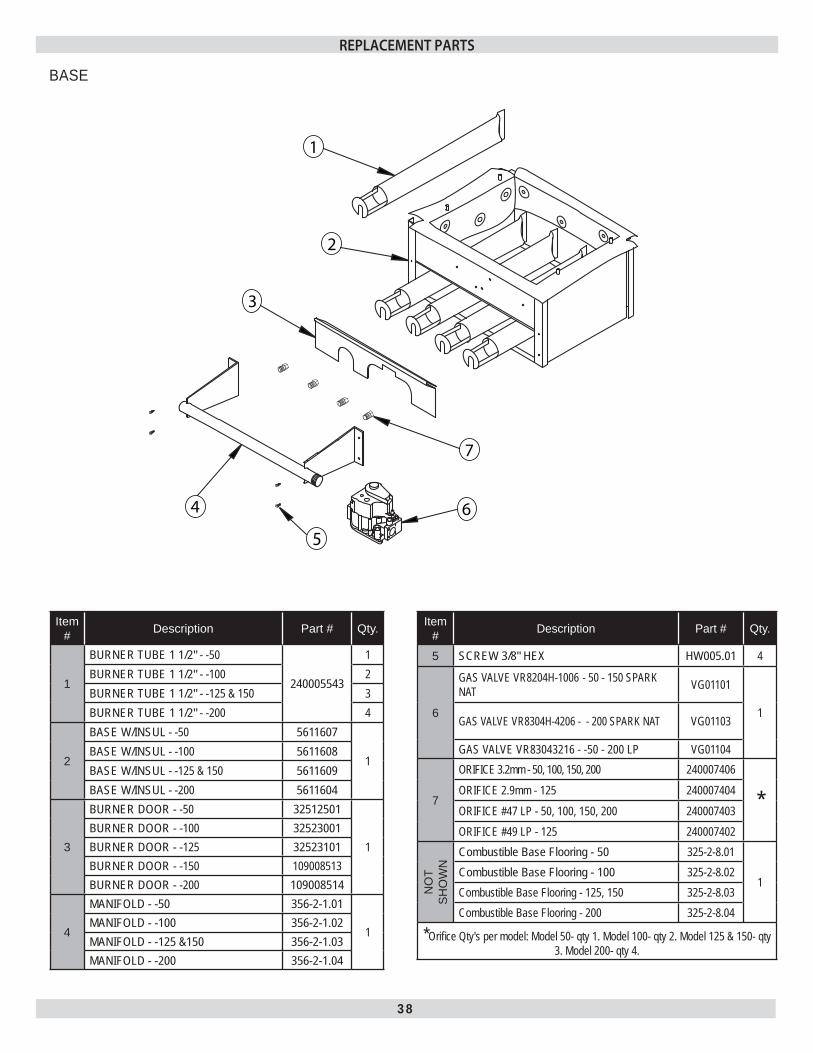
BASE
Item # Description Part # Qty.
1
BURNER TUBE 1 1/2" - -50
240005543
1BURNER TUBE 1 1/2" - -100 2BURNER TUBE 1 1/2" - -125 & 150 3BURNER TUBE 1 1/2" - -200 4
2
BASE W/INSUL - -50 5611607
1BASE W/INSUL - -100 5611608BASE W/INSUL - -125 & 150 5611609BASE W/INSUL - -200 5611604
3
BURNER DOOR - -50 32512501
1BURNER DOOR - -100 32523001BURNER DOOR - -125 32523101BURNER DOOR - -150 109008513BURNER DOOR - -200 109008514
4
MANIFOLD - -50 356-2-1.01
1MANIFOLD - -100 356-2-1.02MANIFOLD - -125 &150 356-2-1.03MANIFOLD - -200 356-2-1.04
Item # Description Part # Qty.
5 SCREW 3/8" HEX HW005.01 4
6
GAS VALVE VR8204H-1006 - 50 - 150 SPARK NAT VG01101
1 GAS VALVE VR8304H-4206 - - 200 SPARK NAT VG01103
GAS VALVE VR83043216 - -50 - 200 LP VG01104
7
ORIFICE 3.2mm - 50, 100, 150, 200 240007406
*ORIFICE 2.9mm - 125 240007404ORIFICE #47 LP - 50, 100, 150, 200 240007403ORIFICE #49 LP - 125 240007402
NO
T SH
OW
N
Combustible Base Flooring - 50 325-2-8.01
1Combustible Base Flooring - 100 325-2-8.02Combustible Base Flooring - 125, 150 325-2-8.03Combustible Base Flooring - 200 325-2-8.04
*Orifi ce Qty's per model: Model 50- qty 1. Model 100- qty 2. Model 125 & 150- qty 3. Model 200- qty 4.
REPLACEMENT PARTS

39
JACKET
ITEM DESCRIPTION PART NUM-BER OTY.
1 PANEL - LEFT 50-200 3162702 1
2
PANEL - FRONT -50 315-2-19.01
1PANEL - FRONT -100 315-2-19.02PANEL - FRONT -125 & 150 315-2-19.03PANEL - FRONT -200 315-2-19.04
3
PANEL - BASE -50 315-2-12.01
1PANEL - BASE -100 315-2-12.02PANEL - BASE -125 & 150 315-2-12.03PANEL - BASE -200 315-2-12.04
4 PANEL - RIGHT -50-200 3162701 1
5
PANEL - SEPARATOR -50 31522401
1PANEL - SEPARATOR -100 31522402PANEL - SEPARATOR -125 & 150 31522403PANEL - SEPARATOR -200 31522404
REPLACEMENT PARTS
40
HEAT EXCHANGER
COMPLETE HEAT EXCHANGER ASSEMBLYHEAT EXCHANGER 2 SECTION - 50 912000001HEAT EXCHANGER 3 SECTION - 100 912000002HEAT EXCHANGER 4 SECTION - 125 &150 912000003HEAT EXCHANGER 5 SECTION - 200 912000004
REPLACEMENT PARTS
41
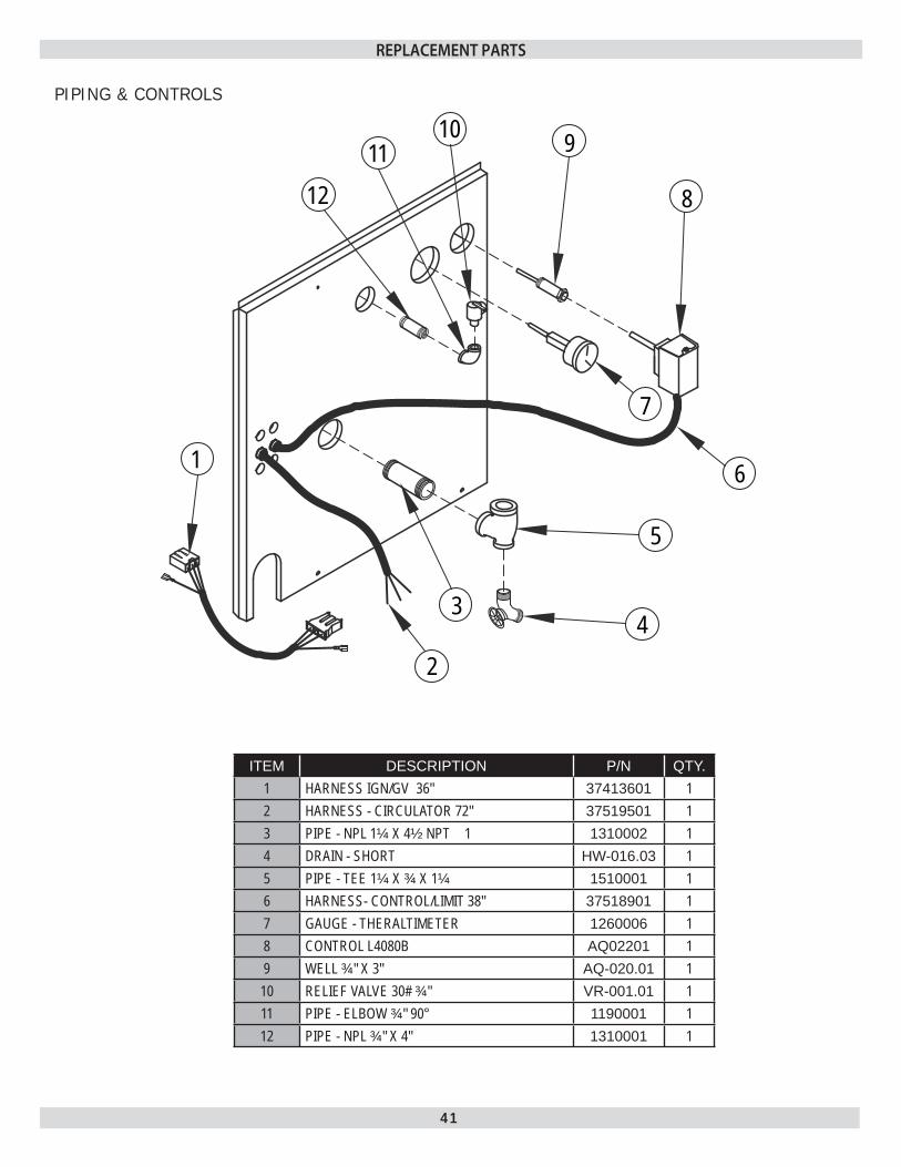
PIPING & CONTROLS
ITEM DESCRIPTION P/N QTY.1 HARNESS IGN/GV 36" 37413601 12 HARNESS - CIRCULATOR 72" 37519501 13 PIPE - NPL 1¼ X 4½ NPT 1 1310002 14 DRAIN - SHORT HW-016.03 15 PIPE - TEE 1¼ X ¾ X 1¼ 1510001 16 HARNESS- CONTROL/LIMIT 38" 37518901 17 GAUGE - THERALTIMETER 1260006 18 CONTROL L4080B AQ02201 19 WELL ¾" X 3" AQ-020.01 1
10 RELIEF VALVE 30# ¾" VR-001.01 111 PIPE - ELBOW ¾" 90° 1190001 112 PIPE - NPL ¾" X 4" 1310001 1
34
5
7
8
91011
12
6
2
1
REPLACEMENT PARTS

42
ELECTRICAL
ITEM DESCRIPTION P/N QTY.1 CONTROL SUPPORT BRACKET 31522201 12 PLT SPARK CONTROL 14662070 13 WIRE ROLLOUT SWITCH 40" 37614501 14 TRANSFORMER - 40VA 550001339 25 CONTROL R8222C-1008 (RELAY) 1410001 16 9 TERM STRIP EF04001 17 SCREW 10-32X5/16 GREEN GROUND HW09001 1
8PRESSURE SWITCH (FS6205A-2413) 50B - 150B SS00801 1PRESSURE SWITCH (FS6273A-3065) 200B ONLY SS00802 1
9 HW TUBE SIL ORANGE 1/8ID HW09701 1FULLY ASSEMBLED CONTROL BRACKET
CONTROL BRACKET SUB-ASSY 50B - 150B 31522901CONTROL BRACKET SUB-ASSY 200B 31522902
(P/N 31522901 & 31522902 INCLUDE PART # 1-8 & ALL WIRING)
REPLACEMENT PARTS
43
1
2
5
64
3
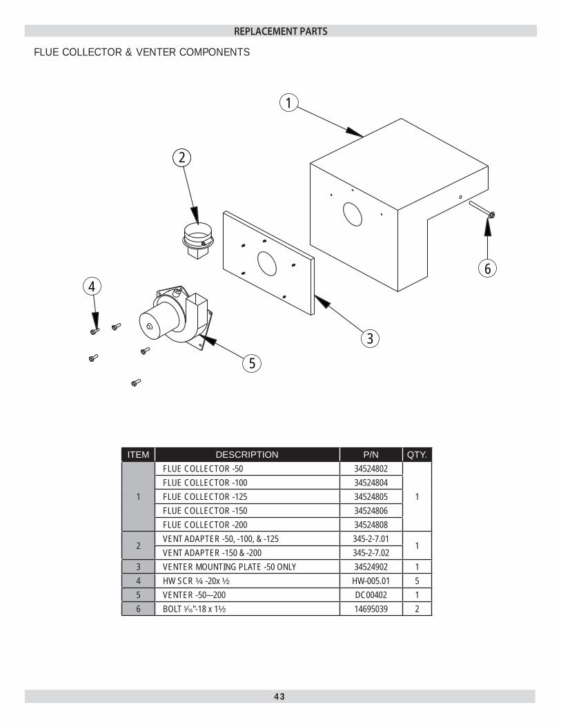
FLUE COLLECTOR & VENTER COMPONENTS
ITEM DESCRIPTION P/N QTY.
1
FLUE COLLECTOR -50 34524802
1FLUE COLLECTOR -100 34524804FLUE COLLECTOR -125 34524805FLUE COLLECTOR -150 34524806FLUE COLLECTOR -200 34524808
2VENT ADAPTER -50, -100, & -125 345-2-7.01
1VENT ADAPTER -150 & -200 345-2-7.02
3 VENTER MOUNTING PLATE -50 ONLY 34524902 14 HW SCR ¼ -20x ½ HW-005.01 55 VENTER -50–-200 DC00402 16 BOLT 5⁄16"-18 x 1½ 14695039 2
REPLACEMENT PARTS

UTICA BOILERS2201 Dwyer Avenue
Utica NY 13501web site: www.ecrinternational.com