Installation, Operation & Maintenance Instructions be read before the furnace is connected to the...
17
Installation, Operation & Maintenance Instructions 1700-1800°C Bottom Loading Furnaces BLF 17/3 to BLF 18/21 This manual is for the guidance of operators of the above products and should be read before the furnace is connected to the electricity supply. 7.4 CONTENTS Section page 1.0 Symbols & Warnings 2 2.0 Installation 4 3.0 Operation 6 4.0 Maintenance 9 5.0 Repairs & Replacements 9 6.0 Fault Analysis 11 7.0 Circuit Diagrams 13 MF23
Transcript of Installation, Operation & Maintenance Instructions be read before the furnace is connected to the...

Installation, Operation & Maintenance Instructions
1700-1800°C Bottom Loading Furnaces BLF 17/3 to BLF 18/21
This manual is for the guidance of operators of the above products and should be read before the furnace is connected to the electricity supply.
7.4
CONTENTS Section page
1.0 Symbols & Warnings 2 2.0 Installation 4 3.0 Operation 6 4.0 Maintenance 9 5.0 Repairs & Replacements 9 6.0 Fault Analysis 11 7.0 Circuit Diagrams 13
MF23
BLF
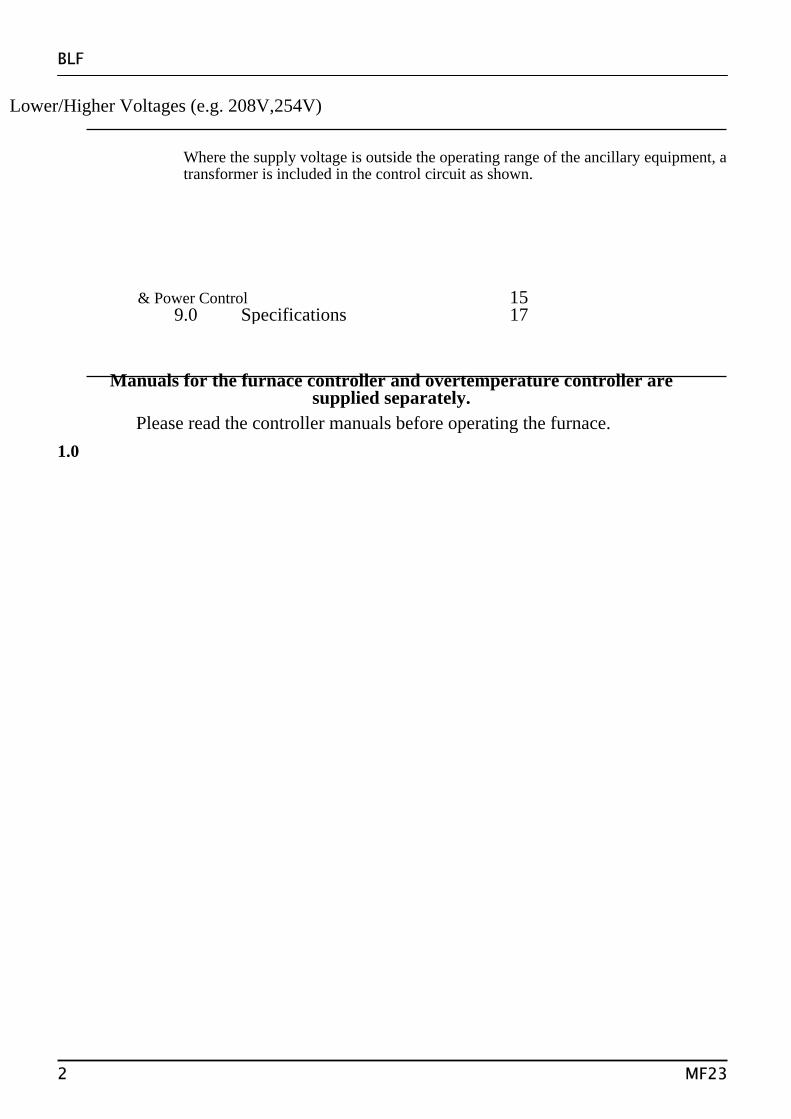
Lower/Higher Voltages (e.g. 208V,254V)
Where the supply voltage is outside the operating range of the ancillary equipment, a transformer is included in the control circuit as shown.
& Power Control 15
Manuals for the furnace controller and overtemperature controller are supplied separately.
9.0 Specifications 17
Please read the controller manuals before operating the furnace. 1.0
2 MF23

BLF
SYMBOLS & WARNINGS 1.1 Switches and Lights
1.2 Warning Symbols
2.0
MF23
Supply Light: when the furnace is connected to the electrical supply the light in the adjacent switch glows
Heat Light: the adjacent light glows or flashes to indicate that power is being supplied to the elements
DANGER of electrical shock– read any warning printed by this symbol.
DANGER – hot surface. Read any warning printed by this symbol.WARNING: all surfaces of a furnace may be hot.
DANGER – read any warning printed by this symbol.
3

BLF
INSTALLATION 2.1 Unpacking & Handling When unpacking or moving the furnace always lift it by its base. The furnace contains a
transformer and is heavy: use two or more people to carry it. Some models may alternatively be lifted by fitting lifting bolts to captive threads in the top of the case.
Remove any packing material.
2.2 Siting & Setting Up Place the furnace in a well ventilated room, away from other sources of heat, and on a surface
which is resistant to accidental spillage of hot materials. Do not mount the furnace on an inflammable surface.
Ensure that there is free space around the furnace. Do not obstruct any of the vents in the case: there are cooling fans in the case which must not be obstructed.
Ensure that the furnace is placed in such a way that it can be quickly switched off or disconnected from the electrical supply - see below.
2.3 Fitting the Heating Elements Wear eye protection when handling the heating elements. See the warning in section 5.6.
The Molybdenum Disilicide elements are EXCEPTIONALLY FRAGILE and are packed separately, together with other items as shown in the list.
separately packed items Most models
BLF 17/8
Elements 6 9 Element clamps 6 18 Element clips * 12 18 Braids* * 1 set 1 set Separators 6 9
* or combined clips and braids may be supplied Transit Clamps – dependent on model: the example shown here is for the 3 litre models; remove
any transit clamps as shown. Remove the complete top access panel using
the hidden screws in holes in the top of the panel: loosen the screws two turns and remove the panel
EHF /3 transit clamps
Fit the heating elements vertically into the chamber. Handle the elements with great care. The installation of these elements is described later in this manual.
Connect the aluminium braids securely as indicated in the element installation instructions.
4 MF23

BLF
2.4 Electrical Connections Connection by a qualified electrician is recommended. The 3 litre models are designed for single phase electrical supplies with or without neutral. Larger
models are designed for 3-phase use. The voltage or range of voltages on which the furnace may be operated is given on the furnace
rating label. Check that the supply voltage is compatible with the voltage on the label, and that the current capacity is sufficient for the amperage on the label, before connection to the supply. A table of the most common ratings is given in section 8.1 of this manual.
Supply cables may be fitted to special order; when fitted, supply-rated fuses are internally fitted, and the cable may be directly wired to an isolator or fitted with a line plug. Where no supply cable is fitted there are no internal supply-rated fuses, and a permanent connection should be made from a fused and isolated supply to the internal terminals after temporary removal of the furnace back panel.
The supply point must be within reach of the furnace operator and must incorporate either an isolating switch which operates on both conductors (single phase) or on all live conductors (two/three phase), or a quickly removable plug.
The supply MUST incorporate an earth (ground). CONNECTION DETAILS supply type Supply Terminal label Cable colour Live-Neutral Reversible or Live-Live 1-phase L Brown To live to either power conductor N Blue To neutral to the other power conductor PE Green/Yellow To earth (ground) to earth (ground) supply Terminal label Cable colour 3-phase L1 Black to phase 1 L2 Black to phase 2 L3 Black to phase 3 N Light Blue to neutral except delta PE Green/Yellow to earth (ground)
DO NOT connect a furnace ordered for three phase use to a single phase supply or to the wrong
type of three phase supply.
3.0
MF23 5

BLF
OPERATION The instructions for operating the temperature controller are given in a separate manual. If the furnace is fitted with a time switch, see also the supplementary manual MS03. If cascade control is fitted, see the supplementary manual MS07.
3.1 Operating Cycle The furnace is fitted with a combined Supply light and Instrument switch. The light is on
whenever the furnace is connected to the supply. The switch cuts off power to the controllers and contactor.
Connect the furnace to the electrical supply. The Supply light should glow and the cooling fans should automatically operate.
Check the hearth control switch for correct operation. The spring return switch stops the hearth in any position, but over-travel is automatically limited. Load the furnace and raise the hearth.
Operate the instrument switch to activate the temperature controller; the O position is off, the I position on. The controller becomes illuminated and goes through a short test cycle.
Adjust the temperature controller – see the controller manual. Set the overtemperature controller to a temperature a little (say 15°C) above the maximum
setpoint of program temperature, according to the instructions in the appropriate manual. Unless a time switch is fitted and is off, the furnace starts to heat up. The Heat light glows brightly
at first, more dimly as the furnace temperature approaches a program setpoint. If the overtemperature trip operates then an indicator or message in the overtemperature controller
flashes, and the heating elements are isolated. Find and correct the cause before resetting the overtemperature controller according to the instructions supplied.
To switch the furnace off, set the Instrument switch to off. The case cooling fans remain on and the chamber can be unloaded. Leave the fans on until the furnace cools to below 300°C. If the furnace is to be left off, isolate it from the electrical supply.
3.2 General Operating Advice Heating element life is shortened by use at temperatures close to maximum. Do not leave the
furnace at high temperature when not required. The maximum temperature is shown on the furnace rating label and on the back page of this manual. The furnace can be cycled between room temperature and maximum without a detrimental effect on element life.
On first installing the elements, and on subsequent element replacement, run the furnace at 1500°C for an hour to create a protective glaze on the element surface.
The thermocouple is intended to sense the temperature near the heating element, but if a large object is placed in the chamber it may record the average temperature of the object and the elements, which can lead to overheating of the elements. Allow large objects to gain heat at a lower temperature and then reset the controller to a temperature close to the desired maximum.
The furnace elements are very susceptible to mechanical shock. Take care when loading or unloading the furnace chamber. Opening the hearth at high temperatures is not recommended, but, if it is necessary, keep the hearth lowered for as short a period as possible. The insulation cools quickly and may crack through thermal shock. Note, though, that the insulation material is susceptible to some surface cracking arising from high temperature cycling; such cracking is not detrimental to the performance of the furnace.
3.3
6 MF23

BLF
Atmospheres & Corrosive Materials In oxidising atmospheres, metal oxides react with the silica layer on the surface of the elements
and may lead to premature failure. Protect the elements from splashes of molten metal and dust when charging the furnace, and from fumes developed when melting, especially from fluxes. Also avoid compounds with a high alkali content.
The furnace is designed for use in oxidising atmospheres, but can be operated successfully in neutral or carburising atmospheres. It may be used with nitrogen, argon or helium atmospheres to 1600°C. Reducing atmospheres are not recommended. Sulphur dioxide in normal concentrations is not harmful, but chlorine, and more so fluorine, strongly attack even oxidised elements and should be avoided.
The furnace is not recommended for burning off carbonaceous materials. Other Carbolite furnaces are available for this application.
When an optional gas inlet is fitted there is a label near the inlet saying "INERT GAS ONLY". In practice inert or oxidising gases may be used, but not combustible or toxic gases. The furnace is not gas tight, so gas usage may be high, and that the chamber is likely always to contain some air. Residual oxygen levels of 1% are to be expected. If an inverted crucible is fitted as an atmosphere container, then gas-tightness is improved, but there is still some leakage around the seal.
The hearth can be protected from abrasion, if required, by the provision of a secondary plate. This consumable item can either be in light weight ceramic fibre or in dense, hard-wearing alumina refractory.
3.4 Operator Safety The furnace incorporates a safety switch which interrupts the heating element circuit when the
hearth is opened. This prevents the user touching a live heating element, but also prevents the furnace from heating up if the hearth is left open.
Avoid burns. Carbolite can supply tongs, face masks, and heat resistant gloves. Before you remove a hot object from the furnace make sure you have a safe place to put it down.
When the hearth is lowered with the furnace hot there is considerable radiative heat. Do not keep near the furnace any inflammable objects or anything which could be damaged by heat.
3.5 Note on Temperature Control The furnace is designed for rapid heating and cooling applications up to 1700°C or 1800°C
(depending on model). The programmer enables the furnace to heat or cool at slower rates as desired, and variable "hold" (dwell) periods can be programmed as required.
The programmer is used in conjunction with a phase angle thyristor Eurocube, which incorporates a current limit potentiometer preset by Carbolite.
The elements are connected in series across the low voltage output of a transformer housed in the furnace case. Molybdenum disilicide elements do not age, so if an element fails it is not necessary to replace the complete set.
3.6 Thermocouples - Warning (1) The output from thermocouples when used regularly at temperatures greater than 1650°C can
deteriorate and decrease with age. Customers are advised periodically to check the thermocouple output, either by a calibration test,
or by comparing the output with a new reference thermocouple which has been subjected to high temperatures for a minimum length of time.
Failure to check the thermocouple may result in overheating of the work and the furnace. (2) The thermocouples fitted to these models give very low outputs below about 600°C, and do not
give accurate readings at low temperatures. The furnaces are not intended to be operated below 600°C.
MF23 7

BLF
3.7 Inverted Crucible Option Take special care over safety considerations: ensure that there is a safe surface on which to place
the crucible when hot. If the process permits, avoid lowering the hearth when the chamber is hot. Depending on the height of the work-piece, it may be necessary to hold the crucible up in the
chamber when placing the work piece on the hearth; ensure that appropriate tongs are available before starting.
Clamp Option This option assists the placing of the crucible over tall workpieces. The “clamp” is provided in the
form of a support shelf which can be fitted to a hinge on the case, and a pair of insulated tongs. With the hearth lowered, place the support shelf on the hinge, and swing to the side. Use the tongs
to lift the crucible up into the chamber, swing the shelf to the centre, and lower the crucible. Place the work-piece. Reverse the procedure above and carefully lower the crucible over the
workpiece. Remove the shelf before raising the hearth.
4.0
8 MF23

BLF
MAINTENANCE 4.1 Routine Maintenance No routine maintenance is required except for the replacement of consumable items as required. The outer surfaces may be cleaned with a damp cloth. Do not allow water to enter the interior of
the case, tube or control box. Do not clean with organic solvents.
4.2 Calibration After prolonged use the controller and/or thermocouple could require recalibration; see the
warning in section 3.5. This would be important for processes which require accurate temperature readings or which use the furnace close to its maximum temperature. A quick check using an independent thermocouple and temperature indicator should be made from time to time to determine whether full calibration is required. Carbolite can supply these items.
Depending on the controller, the controller manual may contain calibration instructions.
4.3 After Sales Service Carbolite’s service division (Thermal Engineering Services) has a team of Service Engineers capable of repair, calibration and preventive maintenance of furnace and oven products at our customers’ premises throughout the world. We also sell spares by mail order. A telephone call or fax often enables a fault to be diagnosed and the necessary spare part despatched.
Each furnace has its own record card at Carbolite. In all correspondence please quote the serial number, model type and voltage given on the rating label of the furnace. The serial number and model type are also given on the front of this booklet when supplied with a furnace.
To contact Thermal Engineering Services or Carbolite see the back page of this manual.
4.4 Recommended Spares Kits Carbolite can supply individual spares, or a kit of the items most likely to be required. Ordering a
kit in advance can save time in the event of a breakdown. Each kit comprises one thermocouple, one sheath, one power thyristor, one door insulation piece, a set of elements and clips and braids. It is advisable also to obtain element clamps and insulators (not included in kit). Individual spares are also available.
When ordering spares please quote the model details as requested above.
4.5 Power Adjustment (Controller) The furnace controller incorporates a power limit parameter OP.Hi which is usually inaccessible to
the operator. Occasionally the power limit is set to zero to permit demonstration of the controls without the
heating elements taking power. In this case the power limit is accessible to the operator and may be reset to its standard value of 100.
4.6 Power Adjustment (Thyristor) The current-limiting thyristor stacks which control power to the elements are fitted with an adjustable resistor which is factory set to limit the maximum current supplied. In the event of a change of supply voltage, or the fitting of a new thyristor, further adjustment may be required.
The maximum element currents for the various models are listed in section 8.2. Please contact Carbolite for further information.
4.7 Insulation Replacement After any replacement of insulation material, run the furnace at 1500°C to burn off volatile matter. Do this is a well ventilated area. Try to ensure the furnace chamber is well ventilated.
5.0
MF23 9

BLF
REPAIRS & REPLACEMENTS 5.1 Safety Warning – Disconnection from Supply Always ensure that the furnace is disconnected from the supply before repair work
is carried out.
5.2 Safety Warning - Refractory Fibrous Insulation This furnace contains refractory fibres in its thermal insulation. These materials
may be in the form of fibre blanket or felt, vacuum formed board or shapes, mineral wool slab or loose fill fibre.
Normal use of the furnace does not result in any significant level of airborne dust from these materials, but much higher levels may be encountered during maintenance or repair.
Whilst there is no evidence of any long term health hazards, we strongly recommend that safety precautions are taken whenever the materials are handled.
Exposure to dust from fibre which has been used at high temperatures may cause respiratory disease. When handling fibre always use an approved mask, eye protection, gloves and long sleeved clothing. Avoid breaking up waste material. Dispose of waste fibre in sealed containers. After handling rinse exposed skin with water before washing gently with soap (not detergent). Wash work clothing separately.
Before commencing any major repairs we recommend reference to the European Ceramic Fibre Industry Association Bulletin No. 11 and the UK Health and Safety Executive Guidance Note EH46.
We can provide further information on request. Alternatively our service division can quote for any repairs to be carried out at your premises or ours.
5.3 Temperature Controller Replacement 2216, 2416, 2408 etc. Ease apart the two lugs at the side; grip the instrument and withdraw it from
its sleeve; push in the replacement.
5.4 Fuse Replacement Access to internal fuses is by removal of the furnace cover near the cable entry point. See section
8.1 for details of fuses fitted.
5.5 Thermocouple Replacement Disconnect the furnace from the supply, and remove the furnace cover or back panel. Make a note of the thermocouple connections. The negative leg of the thermocouple is marked
blue. The “compensating” cable for 1700° and 1800°C thermocouples is plain copper. Disconnect the thermocouple from its terminal block. Bend the metal tag, or release the screw, to release the thermocouple sheath; withdraw the sheath,
and shake out any fragments of thermocouple. Re-assemble with a new thermocouple observing the colour coding, ensuring that the
thermocouple is not twisted as it is being inserted and that the metal tag is bent back, or the screw inserted, to grip the sheath.
10 MF23

BLF
5.6 Element Installation & Replacement Safety Warning – Molybdenum Disilicide elements. The elements form a glazed surface when heated. Internal stresses can form through heating and cooling which render the glaze fragile. The glaze can sometimes splinter into a shower of sharp particles when handled. Always wear eye protection when handling the elements.
Remove the element access cover (see section 2.3). Remove the aluminium braids and clips using fingers or the clip tool provided, depending on the
type of clip (or remove the combined clips and braids, if supplied). Lift out the old element and the insulation block: handle the block with care as it is fragile. Remove the clamps.
Handle the new heating elements with extreme care as they are very fragile. Also, avoid touching the heating surface (the thin part of the element). Carefully unpack the elements and slide over them the insulation blocks. Fix the clamps so that the length of element leg above them is 30mm (most models) or 45mm (BLF 17/8).
Insert the new element; refer to the element connection diagram. Single phase models have all the elements connected in series. Reconnect the braids. Ensure that no braids of clips are touching each other or touching any other furnace parts.
After installing new elements run the furnace at 1500°C for an hour. This creates a protective glaze on the element surface.
Use of Clip Tool larger clips require clip tool, comprising two levers smaller clips do no require clip tool
6.0
MF23 11

BLF
FAULT ANALYSIS A. Furnace Does Not Heat Up
1. The HEAT light is ON
An ohm meter applied to the element circuit shows an open circuit
A heating element has failed
2. The HEAT light is OFF
The controller shows a very high temperature or a code such as S.br
The thermocouple has broken or has a wiring fault
The controller shows a low temperature
The door switch may be faulty or need adjustment
The thyristor fuse may have blown
The power thyristor could be failing to switch on due to internal failure, faulty wiring from the controller, or faulty controller
There are no lights glowing on the controller
The SUPPLY light is ON
The controller may be faulty or not receiving a supply due to a faulty switch or a wiring fault
The SUPPLY light is OFF
Check the supply fuses and any fuses in the furnace control compartment
B. Furnace Overheats
1. The HEAT light goes OFF with the instrument switch
The controller shows a very high temperature
The controller is faulty
The controller shows a low temperature
The thermocouple may have been shorted out or may have been moved out of the furnace
The thermocouple may be mounted the wrong way round
The controller may be faulty 2. The HEAT light
does not go off with the instrument switch and the fault persists when a 2A control fuse is removed from its fuse-holder
The power thyristor has failed “ON”
Check for an accidental wiring fault which could have overloaded the thyristor. Isolate the furnace if this fault persists.
7.0
12 MF23

BLF
CIRCUIT DIAGRAMS 7.1 Single Phase
GR/Y Green/Yellow R Red TC temperature programmer BU Blue OTC overtemperature controller P Pink G Grey
MF23 13
BLF
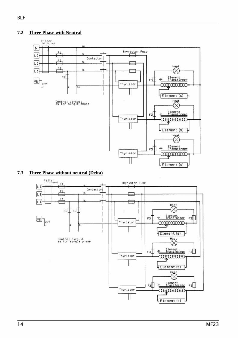
7.2 Three Phase with Neutral 7.3 Three Phase without neutral (Delta)
14 MF23

BLF
PEL1N
F1
F2
transformer
F2
Supply light & Instrument Switch
Filter (if fitted)7.4 Lower/Higher Voltages (e.g. 208V,254V) Where the supply voltage is outside the operating range of the ancillary equipment, a transformer is included in the control circuit as shown.
8.0
MF23 15

BLF
FUSES & POWER CONTROL 8.1 Fuses
F1 to F3 - refer to the circuit diagrams
F1 Internal supply fuses
Fitted if supply cable fitted.
GEC Safeclip of the type shown (glass type F up to 16A)
F2 Auxiliary circuit fuses
2 Amps glass type F 32mm x 6mm
F3 Heat Light fuses
2 Amps glass type F 32mm x 6mm
Thyristor Fuse Ferraz Protistor of the rating shown
Customer fuses
Required if no supply cable fitted. Recommended if cable fitted.
See rating label for amperage; see table below for fuse rating.
The table below gives the fuse rating for the various models. 8.2 Power Control The setting for the power limit parameter in the controller (OP.Hi) should be 100% for all models. The thyristor stacks are set to the secondary (element) maximum currents given in the table.
TABLE OF FUSE AND CURRENT LIMIT VALUES
Model Phases volts supply fuse rating type
thyristor fuse rating
current limit (element circuit)
BLF 17/3 1-phase 220-240V 30-32A NS32 50A 90A BLF 18/3 1-phase 220-240V 30-32A NS32 50A 150A BLF 17/8 3-phase+N 380/220-415/240V 16A glass 25A 82A BLF 17/8 3-phase delta 208, 220-240V 30-32A NS32 25A 82A BLF 18/8 3-phase+N 380/220-415/240V 16A glass 25A 150A BLF 18/8 3-phase delta 208, 220-240V 30-32A NS32 25A 150A BLF 17/21 BLF 18/21
16 MF23

Thank you for reading this data sheet.
For pricing or for further information, please contact us at our UK Office, using the details below.
UK OfficeKeison Products,
P.O. Box 2124, Chelmsford, Essex, CM1 3UP, England.Tel: +44 (0)330 088 0560Fax: +44 (0)1245 808399
Email: [email protected]
Please note - Product designs and specifications are subject to change without notice. The user is responsible for determining the suitability of this product.