INSTALLATION, OPERATION & MAINTENANCE MANUAL · 1 INSTALLATION, OPERATION & MAINTENANCE MANUAL CAM...
16
www.guentner.com.mx 1 INSTALLATION, OPERATION & MAINTENANCE MANUAL CAM – CEM – CDM – CGM - CKM Mediun profile unit coolers COMMERCIAL AIR COOLERS AIR, ELECTRIC AND HOTGAS DEFROST Index 1. Warranty statement 2 2. General Safety Information 3 3. Inspection 3 4. Unloading 4 5. Mounting 4 6. Refrigerant piping 6 7. Expansion valve 7 8. Drain line 7 9. Nozzle 7 10. Wiring 8 11. Evacuation 8 12. Installation 8 13. Start-up 8 14. Maintenance and service 9 15. Electrical data 10 16. Spare Parts 13 17. Trouble shooting 14 18. Reference data 16
-
Upload
hoangkhanh -
Category
Documents
-
view
312 -
download
1
Transcript of INSTALLATION, OPERATION & MAINTENANCE MANUAL · 1 INSTALLATION, OPERATION & MAINTENANCE MANUAL CAM...
www.guentner.com.mx
1
INSTALLATION, OPERATION & MAINTENANCE MANUAL
CAM – CEM – CDM – CGM - CKM
Mediun profile unit coolers
COMMERCIAL AIR COOLERS AIR, ELECTRIC AND HOTGAS DEFROST
Index 1. Warranty statement 2 2. General Safety Information 3
3. Inspection 3 4. Unloading 4 5. Mounting 4
6. Refrigerant piping 6 7. Expansion valve 7 8. Drain line 7 9. Nozzle 7 10. Wiring 8 11. Evacuation 8
12. Installation 8 13. Start-up 8 14. Maintenance and service 9 15. Electrical data 10
16. Spare Parts 13 17. Trouble shooting 14 18. Reference data 16

www.guentner.com.mx
2
1.
Warranty Statement The supplier warrants against defects in workmanship and materials of the product supplied for a period of 24 months from the time of transfer of risk, provided that they are correctly installed and operated within the recommended limits of the manufacturer’s technical documentation. The supplier at its option shall repair, or replace, free of charge to the purchaser all goods which become defective during the warranty period as a result of defects in design, workmanship or materials, fair wear and tear excluded, provided, however, that;
- the application is correct
- operating and installation instructions are complied with - system component and piping design is in accordance with good refrigeration practice - Nitrogen or an inert gas must be introduced into the piping during the brazing of the
piping installation In order to execute the corrective work or replacement supply that appears necessary, within the
supplier’s reasonable discretion, the purchaser must, following communication with the supplier, provide the necessary time and opportunity, or the supplier will be freed from the liability of the defect. The costs arising directly from the corrective work or replacement supply, transport and exchange costs in particular, shall be borne by the purchaser himself. The supplier shall not be liable for costs incurred in dismantling or fitting replacement parts or for any independent inspection undertaken by the purchaser. The purchaser shall return any allegedly defective goods, carriage paid, to the supplier’s works. Upon receipt of the goods and inspection thereof the supplier shall repair or replace, at the supplier’s discretion, the defective goods and return freight, carriage paid, and
without any further expenses. This shall constitute full compliance of the supplier’s obligations. No liability is accepted for the consequences of modifications or repair work being carried out by
the purchaser or a third party incorrectly or without the prior permission of the supplier. It is clearly understood and agreed that any further claims, in particular claims for compensation
for damage and consequential damages not occurring on the supplied item itself, are excluded. Furthermore the supplier shall not be liable to the purchaser, or client of the purchaser, for any direct or indirect damages, injury to persons or property or any consequential loss or loss of profits arising from defective goods or workmanship or from any other cause whatsoever. To obtain warranty service, please contact: [email protected]

www.guentner.com.mx
3
2. GENERAL SAFETY INFORMATION
All installation and maintenance procedures should be performed by qualified personnel already familiarized with the equipment.
All field wiring should match the requirements of the equipment, as well as any local or national codes.
Coil edges and other sharp objects should be met with caution, as they can
cause serious injury. Fan blades are especially sharp, and therefore should be handled only while wearing protective gloves.
All power sources should be disconnected before any type of service work
is performed on the equipment. For cleaning the equipment, reinstall the drain pan after every cleaning session. Failure to follow these steps can result in damaged equipment or personal injury.
Inhalation of certain refrigerants can be harmful, or even fatal. Failure to implement proper detection devices, ventilation, and procedures can result in serious injury or death. Ventilation of all refrigerants should follow all
related regulations, as certain refrigerants are harmful to the environment. For more information, refer to any local or national codes that may apply.
High temperatures can cause damage to the equipment. The expansion valve must be covered in heat absorbent material and the suction line sensor removed while brazing the refrigerant connections.
Never use the refrigeration compressor to evacuate the equipment. Never start the refrigeration compressor if it is in a vacuum.
Fan motors are sealed and do not need lubrication

www.guentner.com.mx
4
3. INSPECTION Each shipment should be carefully checked against the bill of loading at time of receipt. The shipping receipt
should not be signed until all items listed on the bill of loading have been accounted for. Check carefully for any damage. Any and all shortages or damages should be reported to the delivery carrier. Damaged equipment during shipment becomes the delivery agent’s responsibility and should not be returned unless
prior approval has been given. The equipment is pressurized with 29 psi (2 Bars) dry air during manufacturing. If the unit lost pressure
during transportation, contact the Sales Department ([email protected]). For special requirements please contact our factory.
4. UNLOADING
Normal care should be taken while unpacking and uncrating equipment so that damage and injury can be prevented. Heavy equipment should be kept on the original pallet until ready for final installation. While using lifting belts, ensure that a spreader bar is used, and that the belts do not compress the sheet metal construction. When using a truck lift, ensure that the unit is positioned as shown in the picture below.

www.guentner.com.mx
5
5. MOUNTING
The equipment can be mounted using rod hangers, lag screws and/or bolts. Units should be hung with no degree of inclination so that the condensate drainage can be properly maintained. Proper airflow through the unit is essential for efficient performance and maintenance of design storage temperatures. Never install an
evaporator over a doorway. The drain pan should be fitted to the unit only after the installation of the equipment.
DIMENSIONS CAM – CEM – CDM – CGM - CKM
No Fan in mm in mm in mm in mm lbs kg in mm in mm in mm
0125.0… 1 41 3/16 1046 25 1/2 648 20 9/16 522 26 3/4 680 77 35 1/2 12 3/4 19 1 1/4 32
0165.0… 1 41 3/16 1046 25 1/2 648 20 9/16 522 26 3/4 680 82 37 1/2 12 7/8 22 1 1/4 32
0185.0… 2 67 15/16 1726 25 1/2 648 20 9/16 522 53 1/2 1360 119 54 1/2 12 7/8 22 1 1/4 32
0250.0… 2 67 15/16 1726 25 1/2 648 20 9/16 522 53 1/2 1360 130 59 1/2 12 7/8 22 1 1/4 32
0335.0… 2 67 15/16 1726 25 1/2 648 20 9/16 522 53 1/2 1360 143 65 7/8 22 1 3/8 35 1 1/4 32
0375.0… 3 94 3/4 2406 25 1/2 648 20 9/16 522 80 1/4 2040 183 83 7/8 22 1 1/8 28 1 1/4 32
0480.0… 3 94 3/4 2406 25 1/2 648 20 9/16 522 80 1/4 2040 198 90 7/8 22 1 3/8 35 1 1/4 32
0645.0… 4 121 1/2 3086 25 1/2 648 20 9/16 522 53 1/2 1360 265 120 1 1/8 28 1 5/8 42 1 1/4 32
0790.0… 4 121 1/2 3086 25 1/2 648 20 9/16 522 53 1/2 1360 289 131 1 1/8 28 1 5/8 42 1 1/4 32
CAM 6 FPI
Suction
Dimensions Weight
L H E LiquidModel
CAM (AIR DEFROST) Dimensions
B Drain
Connections
No Fan in mm in mm in mm in mm lbs kg in mm in mm in mm
0092.0… 1 41 3/16 1046 25 1/2 648 21 3/4 552 26 3/4 680 117 53 1/2 12 3/4 19 1 1/4 32
0126.0… 1 41 3/16 1046 25 1/2 648 21 3/4 552 26 3/4 680 134 61 1/2 12 7/8 22 1 1/4 32
0160.0… 1 41 3/16 1046 25 1/2 648 21 3/4 552 26 3/4 680 141 64 1/2 12 7/8 22 1 1/4 32
0185.0… 2 67 15/16 1726 25 1/2 648 21 3/4 552 53 1/2 1360 176 80 1/2 12 1 1/8 28 1 1/4 32
0255.0… 2 67 15/16 1726 25 1/2 648 21 3/4 552 53 1/2 1360 201 91 7/8 22 1 1/8 28 1 1/4 32
0356.0… 3 94 3/4 2406 25 1/2 648 21 3/4 552 80 1/4 2040 269 122 7/8 22 1 1/8 28 1 1/4 32
0382.0… 3 94 3/4 2406 25 1/2 648 21 3/4 552 80 1/4 2040 269 122 7/8 22 1 3/8 35 1 1/4 32
0485.0… 3 94 3/4 2406 25 1/2 648 21 3/4 552 80 1/4 2040 304 138 1 1/8 28 1 5/8 42 1 1/4 32
0578.0… 3 94 3/4 2406 25 1/2 648 21 3/4 552 80 1/4 2040 335 152 1 1/8 28 1 5/8 42 1 1/4 32
0620.0… 4 121 1/2 3086 25 1/2 648 21 3/4 552 53 1/2 1360 381 173 1 1/8 28 1 5/8 42 1 1/4 32
0110.0… 1 41 3/16 1046 25 1/2 648 21 3/4 552 26 3/4 680 134 61 1/2 12 7/8 22 1 1/4 32
0175.0… 2 67 15/16 1726 25 1/2 648 21 3/4 552 53 1/2 1360 192 87 1/2 12 1 1/8 28 1 1/4 32
0220.0… 2 67 15/16 1726 25 1/2 648 21 3/4 552 53 1/2 1360 214 97 7/8 22 1 3/8 35 1 1/4 32
0260.0… 3 94 3/4 2406 25 1/2 648 21 3/4 552 80 1/4 2040 271 123 7/8 22 1 3/8 35 1 1/4 32
0331.0… 3 94 3/4 2406 25 1/2 648 21 3/4 552 80 1/4 2040 300 136 1 1/8 28 1 5/8 42 1 1/4 32
0406.0… 4 94 3/4 2406 25 1/2 648 21 3/4 552 80 1/4 2040 328 149 1 1/8 28 1 5/8 42 1 1/4 32
0444.0… 4 121 1/2 3086 25 1/2 648 21 3/4 552 53 1/2 1360 377 171 1 1/8 28 1 5/8 42 1 1/4 32
0540.0… 4 121 1/2 3086 25 1/2 648 21 3/4 552 53 1/2 1360 410 186 1 1/8 28 1 5/8 42 1 1/4 32
CEM - CDM (ELECTRIC DEFROST) DimensionsDimensions
Weight Connections
L H BModel
CEM 6 FPI
CDM 4 FPI
E Liquid Suction Drain

www.guentner.com.mx
6
CAM-CEM-CDM Mounting reference
n = number of units to install
Lr = length of room
NOTES Do not place the cooler directly over or next to a door.
Do not place produce directly in front of the cooler. Do not place coolers in front of each other at a distance less than their air throw indicated in the technical specification sheet.
In the case of electric defrost units, make sure to leave a free space of at least the length of the unit on the electric connection side to remove the heaters in case of failure.
The minimum distance between units must be 6“ for hot gas and air defrost units.
If you have reduced space or special room construction, please contact your local sales office to receive the correct advice on unit mounting.
6. REFRIGERANT PIPING Type, sizing and installation of all piping must be in accordance with the recommended and accepted
practices for Freon refrigeration applications. All low temperature piping should also be insulated in
accordance with standards ASHRAE. Suction traps should be used when and if the suction line rises above the unit cooler.
No Fan in mm in mm in mm in mm lbs kg in mm in mm in mm
0092.0… 1 41 3/16 1046 25 1/2 648 21 3/4 552 26 3/4 680 121 55 1/2 12 3/4 19 1 1/4 32
0126.0… 1 41 3/16 1046 25 1/2 648 21 3/4 552 26 3/4 680 126 57 1/2 12 7/8 22 1 1/4 32
0160.0… 1 41 3/16 1046 25 1/2 648 21 3/4 552 26 3/4 680 130 59 1/2 12 7/8 22 1 1/4 32
0185.0… 2 67 15/16 1726 25 1/2 648 21 3/4 552 53 1/2 1360 168 76 1/2 12 1 1/8 28 1 1/4 32
0255.0… 2 67 15/16 1726 25 1/2 648 21 3/4 552 53 1/2 1360 183 83 7/8 22 1 1/8 28 1 1/4 32
0356.0… 3 94 3/4 2406 25 1/2 648 21 3/4 552 80 1/4 2040 238 108 7/8 22 1 1/8 28 1 1/4 32
0382.0… 3 94 3/4 2406 25 1/2 648 21 3/4 552 80 1/4 2040 238 108 7/8 22 1 3/8 35 1 1/4 32
0485.0… 3 94 3/4 2406 25 1/2 648 21 3/4 552 80 1/4 2040 258 117 1 1/8 28 1 5/8 42 1 1/4 32
0578.0… 3 94 3/4 2406 25 1/2 648 21 3/4 552 80 1/4 2040 276 125 1 1/8 28 1 5/8 42 1 1/4 32
0620.0… 4 121 1/2 3086 25 1/2 648 21 3/4 552 53 1/2 1360 317 144 1 1/8 28 1 5/8 42 1 1/4 32
0110.0… 1 41 3/16 1046 25 1/2 648 21 3/4 552 26 3/4 680 126 57 1/2 12 7/8 22 1 1/4 32
0175.0… 2 67 15/16 1726 25 1/2 648 21 3/4 552 53 1/2 1360 172 78 1/2 12 1 1/8 28 1 1/4 32
0220.0… 2 67 15/16 1726 25 1/2 648 21 3/4 552 53 1/2 1360 185 84 7/8 22 1 3/8 35 1 1/4 32
0260.0… 3 94 3/4 2406 25 1/2 648 21 3/4 552 80 1/4 2040 225 102 7/8 22 1 3/8 35 1 1/4 32
0331.0… 3 94 3/4 2406 25 1/2 648 21 3/4 552 80 1/4 2040 243 110 1 1/8 28 1 5/8 42 1 1/4 32
0406.0… 4 94 3/4 2406 25 1/2 648 21 3/4 552 80 1/4 2040 260 118 1 1/8 28 1 5/8 42 1 1/4 32
0444.0… 4 121 1/2 3086 25 1/2 648 21 3/4 552 53 1/2 1360 295 134 1 1/8 28 1 5/8 42 1 1/4 32
0540.0… 4 121 1/2 3086 25 1/2 648 21 3/4 552 53 1/2 1360 317 144 1 1/8 28 1 5/8 42 1 1/4 32
Suction Drain
CGM 6 FPI
CKM 4 FPI
CGM - CKM (HOT GAS DEFROST) Dimensions
ModelDimensions
Weight Connections
L H B E Liquid

www.guentner.com.mx
7
7. EXPANSION VALVE For direct expansion units, select an expansion valve in accordance with capacity data and as required by
expansion valve manufacturer. Expansion valves with external equalizers should be used. After the temperature has reached design conditions, adjust the expansion valve to obtain 8 to 10º F superheat at the suction line. Expansion valves are to be installed in accordance with the specific manufacturer’s
recommendations. Units that require an external equalized expansion valve must have that line connected. Proper location of the bulb is extremely important to the performance of the coil. Good thermal contact to the suction line is also essential. On solder type valves, a wet cloth wrapped around the valve during installation will protect it from overheating and damage. On multiple evaporator systems, the piping should be arranged
such that the flow from any valve cannot affect the bulb of another.
8. DRAIN LINE The drain line must be pitched to effectively drain condensate. All drain lines subject to freezing temperatures
must have drain line heaters and be insulated. Drain line traps must also be heated to prevent freezing up of the drain line and trap.
9. NOZZLE
R-22 R-404A R-22 R-404A
0125 3/4 1 1/2 0092 1 2 1/2
0165 1 2 0126 1 1/2 3
0185 1 2 0160 2 4
0250 1 1/2 2 1/2 0185 2 5
0335 2 3 0255 3 6
0375 2 1/2 5 0356 3 6
0480 3 5 0382 5 12
0645 4 8 0485 6 15
0790 5 10 0578 8 17
0620 6* 15
0110 1 2
0175 2 4
0220 2 1/2 4
0260 2 1/2 5
0331 3 6
0406 4 10
0444 5 12
0540 6 17
0092 1 2 1/2
0126 1 1/2 3
0160 2 4
0185 2 5
0255 3 6
0356 3 6
0382 5 12
0485 6 15
0578 8 17
0620 6* 15
0110 1 2
0175 2 4
0220 2 1/2 4
0260 2 1/2 5
0331 3 6
0406 4 10
0444 5 12
0540 6 17
* SST Temperature Range from -5°F to -30°F
CDM
CGM
CKM
Notes: Nozzles selected at liquid temperature
between 100°F and 90°F. Any change in the
conditions under which the unit was designed may
affect the performance of it.
If the unit is going to be operated outside this
temperature ranks please consult with factory for
an optimal selection.
SST Temperature Range From 0°F to -30°F
ModelRefrigerant
CEM
SST Temperature Range From 40°F to 10°F
ModelRefrigerant
CAM
www.guentner.com.mx
8
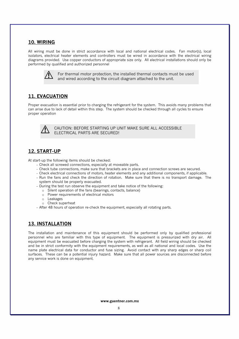
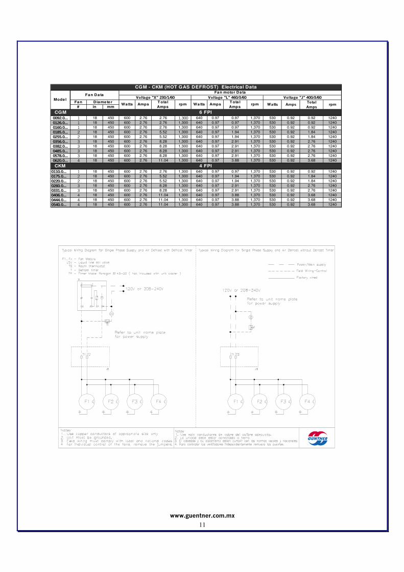
10. WIRING All wiring must be done in strict accordance with local and national electrical codes. Fan motor(s), local
isolators, electrical heater elements and controllers must be wired in accordance with the electrical wiring diagrams provided. Use copper conductors of appropriate size only. All electrical installations should only be performed by qualified and authorized personnel
11. EVACUATION
Proper evacuation is essential prior to charging the refrigerant for the system. This avoids many problems that can arise due to lack of detail within this step. The system should be checked through all cycles to ensure
proper operation
12. START-UP At start-up the following items should be checked:
- Check all screwed connections, especially at moveable parts.
- Check tube connections, make sure that brackets are in place and connection screws are secured. - Check electrical connections of motors, heater elements and any additional components, if applicable.
- Run the fans and check the direction of rotation. Make sure that there is no transport damage. The system should be properly evacuated.
- During the test run observe the equipment and take notice of the following: o Silent operation of the fans (bearings, contacts, balance) o Power requirements of electrical motors
o Leakages o Check superheat
- After 48 hours of operation re-check the equipment, especially all rotating parts.
13. INSTALLATION The installation and maintenance of this equipment should be performed only by qualified professional
personnel who are familiar with this type of equipment. The equipment is pressurized with dry air. All equipment must be evacuated before charging the system with refrigerant. All field wiring should be checked and be in strict conformity with the equipment requirements, as well as all national and local codes. Use the
name plate electrical data for conductor and fuse sizing. Avoid contact with any sharp edges or sharp coil surfaces. These can be a potential injury hazard. Make sure that all power sources are disconnected before
any service work is done on equipment.
For thermal motor protection, the installed thermal contacts must be used and wired according to the circuit diagram attached to the unit.
CAUTION: BEFORE STARTING UP UNIT MAKE SURE ALL ACCESSIBLE ELECTRICAL PARTS ARE SECURED!
www.guentner.com.mx
9
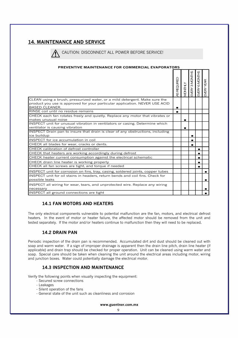
14. MAINTENANCE AND SERVICE
AS REQUIRED
MONTHLY
EVERY 3 MONTHS
EVERY 6 MONTHS
EVERY YEAR
CLEAN using a brush, pressurized water, or a mild detergent. Make sure the
product you use is approved for your particular application. NEVER USE ACID
BASED CLEANER. ■
RINSE coil until no residue remains ■
CHECK each fan rotates freely and quietly. Replace any motor that vibrates or
makes unusual noise ■
INSPECT unit for unusual vibration in ventilators or casing. Determine which
ventilator is causing vibration ■
INSPECT Drain pan to insure that drain is clear of any obstructions, including
ice buildup ■
INSPECT for ice accumulation in coil ■
CHECK all blades for wear, cracks or dents. ■
CHECK calibration of defrost controller ■
CHECK that heaters are working accordingly during defrost ■
CHECK heater current consumption against the electrical schematic ■
CHECK drain line heater is working properly ■
CHECK all fan screws are tight, and torque if needed ■
INSPECT unit for corrosion on fins, tray, casing, soldered joints, copper tubes ■
INSPECT unit for oil stains in headers, return bends and coil fins. Check for
possible leaks ■
INSPECT all wiring for wear, tears, and unprotected wire. Replace any wiring
necessary ■
INSPECT all ground connections are tight ■
PREVENTIVE MAINTENANCE FOR COMMERCIAL EVAPORATORS
14.1 FAN MOTORS AND HEATERS
The only electrical components vulnerable to potential malfunction are the fan, motors, and electrical defrost heaters. In the event of motor or heater failure, the affected motor should be removed from the unit and
tested separately. If the motor and/or heaters continue to malfunction then they will need to be replaced. 14.2 DRAIN PAN
Periodic inspection of the drain pan is recommended. Accumulated dirt and dust should be cleaned out with
soap and warm water. If a sign of improper drainage is apparent then the drain line pitch, drain line heater (if applicable) and drain trap should be checked for proper operation. Unit can be cleaned using warm water and
soap. Special care should be taken when cleaning the unit around the electrical areas including motor, wiring and junction boxes. Water could potentially damage the electrical motor.
14.3 INSPECTION AND MAINTENANCE Verify the following points when visually inspecting the equipment:
- Secured screw connections - Leakages
- Silent operation of the fans - General state of the unit such as cleanliness and corrosion
CAUTION: DISCONNECT ALL POWER BEFORE SERVICE!

www.guentner.com.mx
10
The cleaning of the finned heat exchanger is of the upmost importance to ensure smooth operation and long life of the equipment.
- There is no general rule how often it should be cleaned. Frequency and method of cleaning depend on
the customer and must be determined by the customer´s operating personnel. If need be, ice must be defrosted with a hot air drier or hot water.
- The equipment is always supplied in a clean condition. If, during installation and/or first operation hours, contamination reaches a state where capacity can be affected, it is necessary that the unit is cleaned before operation.
- When cleaning the unit it must be out of operation and all electrical power disconnected. Mechanical Cleaning of the Heat Exchanger
- Blow down the fins with air (only suitable for light, dry and dusty deposits). - Cleaning with compressed air (maximum pressure 6 bar, minimum distance from fins – 8 inches).
- If some contamination is located mainly at the inlet of the fins, clean with a soft brush or use an
industrial vacuum cleaner.
Hydraulic Cleaning of the Heat Exchanger
- For oil containing deposits, it is acceptable to add detergent to the water. Make sure not to deform the
fins. - When using chemical substances, make sure they do not corrode the heat exchanger material and casing. Rinse the heat exchanger and casing after treatment.
- When cleaning with liquid or compressed air, the fans must be switched off. Do not spray them directly.
- Clean the coil from top to bottom in order to allow the contamination to drain downwards. Cleaning must be continued until all contamination has been removed.
- Always clean/spray in the direction of the fins. Never clean at 90° to the fins!
- Maximum allowed vapor pressure is 6 bar. Maximum allowed water pressure before the outlet is 80 to 100 bar.
15. ELECTRICAL DATA
Fan
# in mm
0092.0… 1 18 450 600 2.8 2.8 1,300 640 1.0 1.0 1,370 530 0.9 0.9 1,240 650 1650 2300 10.0 650 1650 2300 3.3 650 1650 2300 3.8
0126.0… 1 18 450 600 2.8 2.8 1,300 640 1.0 1.0 1,370 530 0.9 0.9 1,240 650 2200 2850 12.4 650 2200 2850 4.1 650 2200 2850 4.8
0160.0… 1 18 450 600 2.8 2.8 1,300 640 1.0 1.0 1,370 530 0.9 0.9 1,240 650 2600 3250 14.1 650 2600 3250 4.9 650 2600 3250 5.6
0185.0… 2 18 450 600 2.8 5.5 1,300 640 1.0 1.9 1,370 530 0.9 1.8 1,240 1100 3300 4400 19.1 1100 3300 4400 6.2 1100 3300 4400 7.1
0255.0… 2 18 450 600 2.8 5.5 1,300 640 1.0 1.9 1,370 530 0.9 1.8 1,240 1100 4400 5500 23.9 1100 4400 5500 8.3 1100 4400 5500 9.5
0356.0… 3 18 450 600 2.8 8.3 1,300 640 1.0 2.9 1,370 530 0.9 2.8 1,240 1600 6400 8000 34.8 1600 6400 8000 12.1 1600 6400 8000 13.9
0382.0… 3 18 450 600 2.8 8.3 1,300 640 1.0 2.9 1,370 530 0.9 2.8 1,240 1600 6400 8000 34.8 1600 6400 8000 12.1 1600 6400 8000 13.9
0485.0… 3 18 450 600 2.8 8.3 1,300 640 1.0 2.9 1,370 530 0.9 2.8 1,240 1600 8000 9600 41.7 1600 8000 9600 12.0 1600 8000 9600 13.9
0578.0… 3 18 450 600 2.8 8.3 1,300 640 1.0 2.9 1,370 530 0.9 2.8 1,240 1600 9600 11200 48.7 1600 9600 11200 15.1 1600 9600 11200 17.3
0620.0… 4 18 450 600 2.8 11.0 1,300 640 1.0 3.9 1,370 530 0.9 3.7 1,240 2100 10500 12600 54.8 2100 10500 12600 15.8 2100 10500 12600 18.2
0110.0… 1 18 450 600 2.76 2.76 1,300 640 1 1 1,370 530 0.92 0.92 1,240 1100 1650 2750 12.0 1100 1650 2750 4.1 1100 1650 2750 4.8
0175.0… 2 18 450 600 2.76 5.52 1,300 640 1 2 1,370 530 0.92 1.84 1,240 1700 2550 4250 18.5 1700 2550 4250 6.4 1700 2550 4250 7.4
0220.0… 2 18 450 600 2.76 5.52 1,300 640 1 2 1,370 530 0.92 1.84 1,240 1700 3400 5100 22.2 1700 3400 5100 6.4 1700 3400 5100 7.4
0260.0… 3 18 450 600 2.76 8.28 1,300 640 1 3 1,370 530 0.92 2.76 1,240 2000 4000 6000 26.1 2000 4000 6000 7.5 2000 4000 6000 8.7
0331.0… 3 18 450 600 2.76 8.28 1,300 640 1 3 1,370 530 0.92 2.76 1,240 2000 5000 7000 30.4 2000 5000 7000 9.4 2000 5000 7000 10.8
0406.0… 4 18 450 600 2.76 11.04 1,300 640 1 4 1,370 530 0.92 3.68 1,240 2000 6000 8000 34.8 2000 6000 8000 11.3 2000 6000 8000 13.0
0444.0… 4 18 450 600 2.76 11.04 1,300 640 1 4 1,370 530 0.92 3.68 1,240 2600 6500 9100 39.6 2600 6500 9100 12.2 2600 6500 9100 14.1
0540.0… 4 18 450 600 2.76 11.04 1,300 640 1 4 1,370 530 0.92 3.68 1,240 2600 7800 10400 45.2 2600 7800 10400 14.7 2600 7800 10400 16.9
Fan Da taVoltage "X" 230/1/60 Voltage "L" 460/3/60Voltage "J" 400/3/60Voltage "L" 460/3/60
Heate r Da ta
CEM - CDM (ELECTRIC DEFROST) Electrical Data
rpm
Mode l Voltage "X" 230/1/60
Total
Amp
Diameter
Fan motor Da ta
Watts AmpTray
WattsWatts Amp
Total
Amprpm
Voltage "J" 400/3/60
Total
Amp
Tray
Watts
Coil
Watts
Total
Watts
Tray
Watts
Coil
Watts
Total
Watts
CEM 6 FPI
CDM 4 FPI
Total
Watts
Total
Amprpm Watts Amp
Total
Amp
Total
Amp
Coil
Watts
Fans
CAM0125.0… 1 16 400 260 1.14 1.14 1260 230 0.40 0.4 1520 205 0.36 0.36 1430
0165.0… 1 16 400 260 1.14 1.14 1260 230 0.40 0.4 1520 205 0.36 0.36 1430
0185.0… 2 16 400 260 1.14 2.28 1260 230 0.40 0.8 1520 205 0.36 0.72 1430
0250.0… 2 16 400 260 1.14 2.28 1260 230 0.40 0.8 1520 205 0.36 0.72 1430
0335.0… 2 16 400 260 1.14 2.28 1260 230 0.40 0.8 1520 205 0.36 0.72 1430
0375.0… 3 16 400 260 1.14 3.42 1260 230 0.40 1.2 1520 205 0.36 1.08 1430
0480.0… 3 16 400 260 1.14 3.42 1260 230 0.40 1.2 1520 205 0.36 1.08 1430
0645.0… 4 16 400 260 1.14 4.56 1260 230 0.40 1.6 1520 205 0.36 1.44 1430
0790.0… 4 16 400 260 1.14 4.56 1260 230 0.40 1.6 1520 205 0.36 1.44 1430
6 FPI
Watts AmpsTotal
Ampsrpm
Voltage "J" 400/3/60
Fan motor Data
CAM (AIR D EFROS T) E lectrica l D ata
# in mm WattsTotal
Ampsrpm rpm
Voltage "L" 460/3/60
Amps Watts AmpsTotal
Amps
Fan Data
DiameterModel
Voltage "X" 230/1/60
www.guentner.com.mx
11
Fan
# in mm
CGM
0092.0… 1 18 450 600 2.76 2.76 1,300 640 0.97 0.97 1,370 530 0.92 0.92 1240
0126.0… 1 18 450 600 2.76 2.76 1,300 640 0.97 0.97 1,370 530 0.92 0.92 1240
0160.0… 1 18 450 600 2.76 2.76 1,300 640 0.97 0.97 1,370 530 0.92 0.92 1240
0185.0… 2 18 450 600 2.76 5.52 1,300 640 0.97 1.94 1,370 530 0.92 1.84 1240
0255.0… 2 18 450 600 2.76 5.52 1,300 640 0.97 1.94 1,370 530 0.92 1.84 1240
0356.0… 3 18 450 600 2.76 8.28 1,300 640 0.97 2.91 1,370 530 0.92 2.76 1240
0382.0… 3 18 450 600 2.76 8.28 1,300 640 0.97 2.91 1,370 530 0.92 2.76 1240
0485.0… 3 18 450 600 2.76 8.28 1,300 640 0.97 2.91 1,370 530 0.92 2.76 1240
0578.0… 3 18 450 600 2.76 8.28 1,300 640 0.97 2.91 1,370 530 0.92 2.76 1240
0620.0… 4 18 450 600 2.76 11.04 1,300 640 0.97 3.88 1,370 530 0.92 3.68 1240
CKM
0110.0… 1 18 450 600 2.76 2.76 1,300 640 0.97 0.97 1,370 530 0.92 0.92 1240
0175.0… 2 18 450 600 2.76 5.52 1,300 640 0.97 1.94 1,370 530 0.92 1.84 1240
0220.0… 2 18 450 600 2.76 5.52 1,300 640 0.97 1.94 1,370 530 0.92 1.84 1240
0260.0… 3 18 450 600 2.76 8.28 1,300 640 0.97 2.91 1,370 530 0.92 2.76 1240
0331.0… 3 18 450 600 2.76 8.28 1,300 640 0.97 2.91 1,370 530 0.92 2.76 1240
0406.0… 4 18 450 600 2.76 11.04 1,300 640 0.97 3.88 1,370 530 0.92 3.68 1240
0444.0… 4 18 450 600 2.76 11.04 1,300 640 0.97 3.88 1,370 530 0.92 3.68 1240
0540.0… 4 18 450 600 2.76 11.04 1,300 640 0.97 3.88 1,370 530 0.92 3.68 1240
6 FPI
4 FPI
Watts AmpsTotal
Ampsrpm
T ota l
Ampsrpm Wa tts rpm
ModelVoltage "X" 230/1/60
T ota l
Amps
Diamete rWatts Amps
Fan Data
Amps
Voltage "J" 400/3/60Voltage "L" 460/3/60
Fan motor Data
CGM - CKM (HOT GAS DEFROST) Electrical Data

www.guentner.com.mx
12
www.guentner.com.mx
13
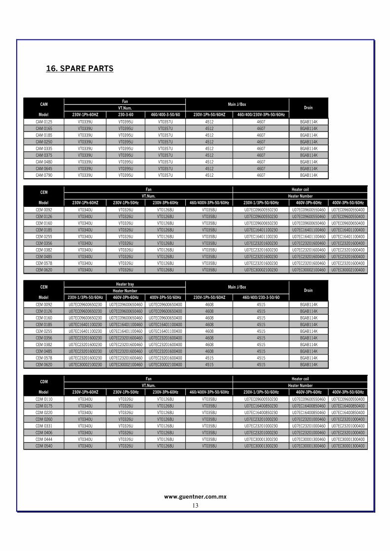
16. SPARE PARTS
Model 230V-1Ph-60HZ 230-3-60 460/400-3-50/60 230V-1Ph-50/60HZ 460/400/230V-3Ph-50/60Hz
CAM 0125 VT0339U VT0395U VT0357U 4512 4607 BGAB114K
CAM 0165 VT0339U VT0395U VT0357U 4512 4607 BGAB114K
CAM 0185 VT0339U VT0395U VT0357U 4512 4607 BGAB114K
CAM 0250 VT0339U VT0395U VT0357U 4512 4607 BGAB114K
CAM 0335 VT0339U VT0395U VT0357U 4512 4607 BGAB114K
CAM 0375 VT0339U VT0395U VT0357U 4512 4607 BGAB114K
CAM 0480 VT0339U VT0395U VT0357U 4512 4607 BGAB114K
CAM 0645 VT0339U VT0395U VT0357U 4512 4607 BGAB114K
CAM 0790 VT0339U VT0395U VT0357U 4512 4607 BGAB114K
Model 230V-1Ph-60HZ 230V-1Ph-50Hz 230V-3Ph-60Hz 460/400V-3Ph-50/60Hz 230V-1/3Ph-50/60Hz 460V-3Ph-60Hz 400V-3Ph-50/60Hz
CEM 0092 VT0340U VT0326U VT01268U VT0358U U07EC09600550230 U07EC09600550460 U07EC09600550400
CEM 0126 VT0340U VT0326U VT01268U VT0358U U07EC09600550230 U07EC09600550460 U07EC09600550400
CEM 0160 VT0340U VT0326U VT01268U VT0358U U07EC09600650230 U07EC09600650460 U07EC09600650400
CEM 0185 VT0340U VT0326U VT01268U VT0358U U07EC16401100230 U07EC16401100460 U07EC16401100400
CEM 0255 VT0340U VT0326U VT01268U VT0358U U07EC16401100230 U07EC16401100460 U07EC16401100400
CEM 0356 VT0340U VT0326U VT01268U VT0358U U07EC23201600230 U07EC23201600460 U07EC23201600400
CEM 0382 VT0340U VT0326U VT01268U VT0358U U07EC23201600230 U07EC23201600460 U07EC23201600400
CEM 0485 VT0340U VT0326U VT01268U VT0358U U07EC23201600230 U07EC23201600460 U07EC23201600400
CEM 0578 VT0340U VT0326U VT01268U VT0358U U07EC23201600230 U07EC23201600460 U07EC23201600400
CEM 0620 VT0340U VT0326U VT01268U VT0358U U07EC30002100230 U07EC30002100460 U07EC30002100400
Model 230V-1/3Ph-50/60Hz 460V-3Ph-60Hz 400V-3Ph-50/60Hz 230V-1Ph-50/60HZ 460/400/230-3-50/60
CEM 0092 U07EC09600650230 U07EC09600650460 U07EC09600650400 4608 4515 BGAB114K
CEM 0126 U07EC09600650230 U07EC09600650460 U07EC09600650400 4608 4515 BGAB114K
CEM 0160 U07EC09600650230 U07EC09600650460 U07EC09600650400 4608 4515 BGAB114K
CEM 0185 U07EC16401100230 U07EC16401100460 U07EC16401100400 4608 4515 BGAB114K
CEM 0255 U07EC16401100230 U07EC16401100460 U07EC16401100400 4608 4515 BGAB114K
CEM 0356 U07EC23201600230 U07EC23201600460 U07EC23201600400 4608 4515 BGAB114K
CEM 0382 U07EC23201600230 U07EC23201600460 U07EC23201600400 4608 4515 BGAB114K
CEM 0485 U07EC23201600230 U07EC23201600460 U07EC23201600400 4608 4515 BGAB114K
CEM 0578 U07EC23201600230 U07EC23201600460 U07EC23201600400 4515 4515 BGAB114K
CEM 0620 U07EC30002100230 U07EC30002100460 U07EC30002100400 4515 4515 BGAB114K
Model 230V-1Ph-60HZ 230V-1Ph-50Hz 230V-3Ph-60Hz 460/400V-3Ph-50/60Hz 230V-1/3Ph-50/60Hz 460V-3Ph-60Hz 400V-3Ph-50/60Hz
CDM 0110 VT0340U VT0326U VT01268U VT0358U U07EC09600550230 U07EC09600550460 U07EC09600550400
CDM 0175 VT0340U VT0326U VT01268U VT0358U U07EC16400850230 U07EC16400850460 U07EC16400850400
CDM 0220 VT0340U VT0326U VT01268U VT0358U U07EC16400850230 U07EC16400850460 U07EC16400850400
CDM 0260 VT0340U VT0326U VT01268U VT0358U U07EC23201000230 U07EC23201000460 U07EC23201000400
CDM 0331 VT0340U VT0326U VT01268U VT0358U U07EC23201000230 U07EC23201000460 U07EC23201000400
CDM 0406 VT0340U VT0326U VT01268U VT0358U U07EC23201000230 U07EC23201000460 U07EC23201000400
CDM 0444 VT0340U VT0326U VT01268U VT0358U U07EC30001300230 U07EC30001300460 U07EC30001300400
CDM 0540 VT0340U VT0326U VT01268U VT0358U U07EC30001300230 U07EC30001300460 U07EC30001300400
CAMFan
Main J/Box Drain VT.Num.
CEMFan Heater coil
CDMFan Heater coil
VT.Num. Heater Number
VT.Num. Heater Number
CEMHeater tray
Main J/Box Drain Heater Number

www.guentner.com.mx
14
Model Designation X, W, V 460V-3Ph-60Hz 400V-3Ph-50/60HZ 230V-1Ph-50/60HZ 230/460/400V-3Ph-50/60Hz
CDM 0110 U07EC09600550230 U07EC09600550460 U07EC09600550400 4608 4515 BGAB114K
CDM 0175 U07EC16400850230 U07EC16400850460 U07EC16400850400 4608 4515 BGAB114K
CDM 0220 U07EC16400850230 U07EC16400850460 U07EC16400850400 4608 4515 BGAB114K
CDM 0260 U07EC23201000230 U07EC23201000460 U07EC23201000400 4608 4515 BGAB114K
CDM 0331 U07EC23201000230 U07EC23201000460 U07EC23201000400 4608 4515 BGAB114K
CDM 0406 U07EC23201000230 U07EC23201000460 U07EC23201000400 4608 4515 BGAB114K
CDM 0444 U07EC30001300230 U07EC30001300460 U07EC30001300400 4608 4515 BGAB114K
CDM 0540 U07EC30001300230 U07EC30001300460 U07EC30001300400 4608 4515 BGAB114K
Model 230V-1Ph-60HZ 230V-1Ph-50HZ 230V-3Ph-60Hz 460/400/230V-3Ph-60Hz 230V-1Ph/3Ph-50/60z 460V-3Ph-60Hz 400V-3Ph-50/60Hz
CGM 0092 VT0340U VT0326U VT01268U VT0358U U07EC09600650230 U07EC09600650460 U07EC09600650400
CGM 0126 VT0340U VT0326U VT01268U VT0358U U07EC09600650230 U07EC09600650460 U07EC09600650400
CGM 0160 VT0340U VT0326U VT01268U VT0358U U07EC09600650230 U07EC09600650460 U07EC09600650400
CGM 0185 VT0340U VT0326U VT01268U VT0358U U07EC16401100230 U07EC16401100460 U07EC16401100400
CGM 0255 VT0340U VT0326U VT01268U VT0358U U07EC16401100230 U07EC16401100460 U07EC16401100400
CGM 0356 VT0340U VT0326U VT01268U VT0358U U07EC23201600230 U07EC23201600460 U07EC23201600400
CGM 0382 VT0340U VT0326U VT01268U VT0358U U07EC23201600230 U07EC23201600460 U07EC23201600400
CGM 0485 VT0340U VT0326U VT01268U VT0358U U07EC23201600230 U07EC23201600460 U07EC23201600400
CGM 0578 VT0340U VT0326U VT01268U VT0358U U07EC23201600230 U07EC23201600460 U07EC23201600400
CGM 0620 VT0340U VT0326U VT01268U VT0358U U07EC30002100230 U07EC30002100460 U07EC30002100400
Drain
Model 230V-1Ph-50/60HZ 230/460/400V-3Ph-50/60Hz
CGM 0092 4607/4608 4607 BGAB114K
CGM 0126 4607/4608 4607 BGAB114K
CGM 0160 4607/4608 4607 BGAB114K
CGM 0185 4607/2608 4607 BGAB114K
CGM 0255 4607/4608 4607 BGAB114K
CGM 0356 4607/4608 4607 BGAB114K
CGM 0382 4607/4608 4607 BGAB114K
CGM 0485 4607/4608 4607 BGAB114K
CGM 0578 4607/4608 4607 BGAB114K
CGM 0620 4607/4608 4607 BGAB114K
Model 230V-1Ph-60HZ 230V-1Ph-50HZ 230V-3Ph-60Hz 460/400/230V-3Ph-60Hz 230V-1Ph/3Ph-50/60z 460V-3Ph-60Hz 400V-3Ph-50/60Hz
CKM 0110 VT0340U VT0326U VT01268U VT0358U U07EC09600550230 U07EC09600550460 U07EC09600550400
CKM 0175 VT0340U VT0326U VT01268U VT0358U U07EC16400850230 U07EC16400850460 U07EC16400850400
CKM 0220 VT0340U VT0326U VT01268U VT0358U U07EC16400850230 U07EC16400850460 U07EC16400850400
CKM 0260 VT0340U VT0326U VT01268U VT0358U U07EC23201000230 U07EC23201000460 U07EC23201000400
CKM 0331 VT0340U VT0326U VT01268U VT0358U U07EC23201000230 U07EC23201000460 U07EC23201000400
CKM 0406 VT0340U VT0326U VT01268U VT0358U U07EC23201000230 U07EC23201000460 U07EC23201000400
CKM 0444 VT0340U VT0326U VT01268U VT0358U U07EC30001300230 U07EC30001300460 U07EC30001300400
CKM 0540 VT0340U VT0326U VT01268U VT0358U U07EC30001300230 U07EC30001300460 U07EC30001300400
CKMFan Heater tray
VT.Num. Heater Number
CGMFan Heater tray
CGM Main J/Box
VT.Num. Heater Number
Drain CDM
Heater trayMain J/Box
Heater Number
www.guentner.com.mx
15
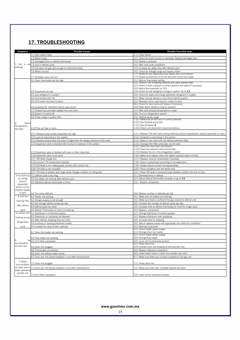
17. TROUBLESHOOTING
Symptoms Possible Causes Possible Corrective steps
1.1 Main switch Open 1.1.1 Close Switch
1.2 Blown Fuses 1.2.1 Check for short circuits or overloads. Replace damaged fuse
1.3 Damaged timer or defrost thermostat 1.3.1 Replace controller
1.4 Unit in defrost cycle 1.4.1 Wait until cycle completion
1.5 Coil does not get cold enough to reset thermostat 1.5.1 Increase fan delay time after defrost cycle
1.6 Motor is burnt 1.6.1 Check for Voltage surge and replace motor
1.7 Ventilator does not turn
1.7.1 Check for any obstruction (ice, debris, etc..) and remove
1.7.2 Check junction box in fan for any short circuit and repair
2.1 Room thermostat set too high 2.1.1 Reduce thermostat setting
2.2 Superheat too high
2.2.1 Check if TXV is feeding correctly and clean strainer filter.
2.2.2 Check if bulb is placed in correct position and adjust if necessary.
2.2.3 Adjust the superheat on TXV.
2.2.4 Check for low refrigerant charge in system. Go to 2.3
2.3 Low refrigerant in system 2.3.1 Check for leaks and charge additional refrigerant in system
2.4 Coil blocked with Ice 2.4.1 Make manual defrost in coil. Check defrost system.
2.5 Unit cooler too close to doors 2.5.1 Relocate unit or add strip/air curtain to door
2.6 Excessive Air infiltration due to open doors
2.6.1 Check for door seals and replace if necessary
2.6.2 Keep doors closed as long as possible
2.7 Product has just been loaded into cold room 2.7.1 Wait until product temperature is lower
2.8 System is turned off 2.8.1 Turn on refrigeration system
2.9 Power surge in system fails 2.9.1 Restore power surge
2.10 Poor air flow in room
2.10.1 Make sure all fans turn in correct direction
2.10.2 See Possible cause 1.7
2.10.3 See Symptom 4.
2.10.4 Check unit placement recommendations
2.11 Pressure drop across evaporator too high 2.11.1 Replace TXV with valve having external pressure equalization, adjust superheat on valve
2.12 Lack of subcooling in the system 2.12.1 Establish a subcooling in the system
2.13 Pressure drop across the valve is larger than the design pressure of the valve 2.13.1 Select a new valve with the desired pressure drop.
2.14 Expansion valve is blocked with ice due to moisture in the system 2.14.1 Change drier filter, and clean ice off valve
2.15 Expansion valve is blocked with wax or other impurities
2.15.1 Clean the valve port, and strainer
2.15.2 Clean the solenoid valve and its filter
2.15.3 Replace the oil in the refrigeration system
2.16 Expansion valve is too small 2.16.1 Select and replace valve with higher capacity valve or orifice.
2.17 TXV Bulb charge lost 2.17.1 Replace valve (or powerhead if possible)
2.18 Incorrect TXV powerhead selected 2.18.1 Select a powerhead according to the application.
2.19 TXV Bulb is not making good contact with suction line 2.19.1 Fasten bulb to suction line appropiately
2.20 TXV bulb is not insulated 2.20.1 Place insulation over the whole bulb
2.21 TXV bulb is located near large valves, flanges, headers, or rising pipe. 2.21.1 Place TXV bulb in horizontal pipe between suction line and oil trap.
3.1 Defrost cycle is too long 3.1.1 Decrease time on defrost
3.2 Fan delay not working after defrost cycle. 3.2.1 Adjust defrost thermostat correctly, or go to 3.3
3.3 Defective defrost thermostat or timer 3.3.1 Replace component
3.4 Too many defrosts 3.4.1 Reduce number of defrosts per day
4.1 Heater not working 4.1.1 Make sure all heaters are working.
4.2 Hot gas supply is not enough 4.2.1 Make sure there is sufficient hot gas volume to defrost unit.
4.3 Not enough defrost cycles per day 4.3.1 Increase the number of defrost cycles per day
4.4 Defrost cycle too short 4.4.1 Increase time on defrost thermostat or timer for longer cycle
4.5 Defrost Thermostat or timer not working 4.5.1 Replace component
5.1 Distributor in horizontal position 5.1.1 Change distributor to vertical position
5.2 Distributor or capillaries are blocked 5.2.1 Replace distributor with capillaries
5.3 After defrost, dripping time too short 5.3.1 Increase time for dripping
5.4 Incorrect or missing distributor nozzle 5.4.1 Add or replace nozzle with appropiate size orifice for conditions
5.5 Located too close to door opening 5.5.1 Relocate evaporator
6.1 Drain line heater not working
6.1.1 Check heater power supply
6.1.2 Change drain line heater
6.2 Tray heater not working
6.2.1 Check heater power supply
6.2.2 Change tray heater
6.3 Unit tilted unproperly 6.3.1 Level unit to horizontal position
6.4 Drain line plugged
6.4.1 Clean drain line
6.4.2 Insulate drain line properly (if blocked with ice)
6.6 Thermostat not working 6.6.1 Replace defective component
6.6 Drain line without water tramp 6.6.1 Install water tramp in drain line outside cold room
6.7 Drain pan not placed properly in unit after mainteinance 6.7.1 Make sure drain pan is close to heaters or hot gas coil.
7.1 Drain line plugged 7.1.1 Clean drain line
7.2 Drain pan not placed properly in unit after mainteinance 7.2.1 Make sure drain pan is leveled towards the back
7.3 Unit tilted unproperly 7.3.1 Level unit to horizontal position
5. Uneven coil
frosting during
refrigeration
cycle
6. Ice
accumulation
on drain pan
7. Water
accumulation
on drain pan or
water spreading
outside unit
1. Fan is not
working
2. Room
Temperature
too High
3. Ice build-up
on ceiling
around
evaporator
and/or on fan
nozzles, blades,
or grill
4. Coil not
clearing frost
after defrost
cycle
www.guentner.com.mx
16
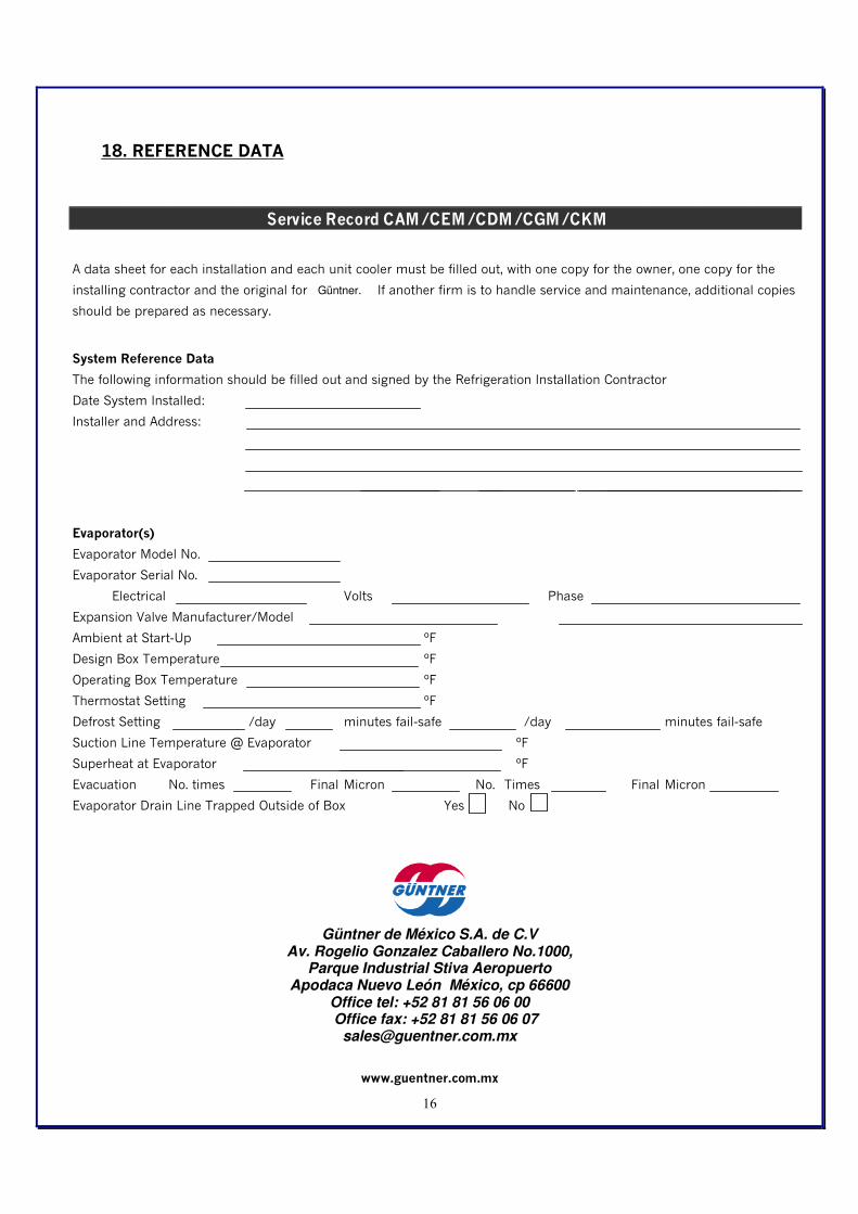
18. REFERENCE DATA
Güntner de México S.A. de C.V Av. Rogelio Gonzalez Caballero No.1000,
Parque Industrial Stiva Aeropuerto Apodaca Nuevo León México, cp 66600
Office tel: +52 81 81 56 06 00 Office fax: +52 81 81 56 06 07
Service Record CAM / CEM / CDM / CGM / CKM
A data sheet for each installation and each unit cooler must be filled out, with one copy for the owner, one copy for the
installing contractor and the original for Coilexpert. If another firm is to handle service and maintenance, additional copies
should be prepared as necessary.
System Reference Data
The following information should be filled out and signed by the Refrigeration Installation Contractor
Date System Installed:
Installer and Address:
Evaporator(s)
Evaporator Model No.
Evaporator Serial No.
Electrical Volts Phase
Expansion Valve Manufacturer/Model
Ambient at Start-Up ºF
Design Box Temperature ºF
Operating Box Temperature ºF
Thermostat Setting ºF
Defrost Setting /day minutes fail-safe /day minutes fail-safe
Suction Line Temperature @ Evaporator ºF
Superheat at Evaporator ºF
Evacuation No. times Final Micron No. Times Final Micron
Evaporator Drain Line Trapped Outside of Box Yes No
Güntner.