INSTALLATION, OPERATION AND SERVICE MANUAL SR4 … · operating turntable. 1.2.7 During Operation...
23
INSTALLATION, OPERATION AND SERVICE MANUAL SR4 Manual Turntable P.O. Box 1058 • 1058 West Industrial Avenue • Guthrie, OK 73044-1058 • 888-811-9876 • 405-282-5200 • FAX: 405-282-3302 • www.autoquip.com Item #830SR4 Version 3.1
Transcript of INSTALLATION, OPERATION AND SERVICE MANUAL SR4 … · operating turntable. 1.2.7 During Operation...
1
INSTALLATION, OPERATION AND SERVICE MANUAL
SR4 Manual Turntable
P.O. Box 1058 • 1058 West Industrial Avenue • Guthrie, OK 73044-1058 • 888-811-9876 • 405-282-5200 • FAX: 405-282-3302 • www.autoquip.com
Item #830SR4 Version 3.1
johnstonj
Placed Image
2
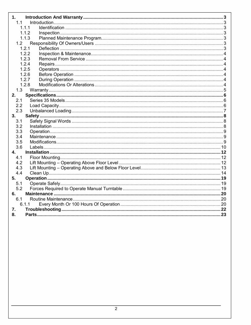
1. Introduction And Warranty ............................................................................................................. 3 1.1 Introduction .................................................................................................................................... 3
1.1.1 Identification ........................................................................................................................... 3 1.1.2 Inspection ............................................................................................................................... 3 1.1.3 Planned Maintenance Program............................................................................................... 3
1.2 Responsibility Of Owners/Users .................................................................................................... 3 1.2.1 Deflection ............................................................................................................................... 3 1.2.2 Inspection & Maintenance ....................................................................................................... 4 1.2.3 Removal From Service ........................................................................................................... 4 1.2.4 Repairs ................................................................................................................................... 4 1.2.5 Operators ............................................................................................................................... 4 1.2.6 Before Operation .................................................................................................................... 4 1.2.7 During Operation .................................................................................................................... 4 1.2.8 Modifications Or Alterations .................................................................................................... 4
1.3 Warranty ........................................................................................................................................ 5 2. Specifications .................................................................................................................................. 6
2.1 Series 35 Models ........................................................................................................................... 6 2.2 Load Capacity ................................................................................................................................ 6 2.3 Unbalanced Loading ...................................................................................................................... 7
3. Safety ............................................................................................................................................... 8 3.1 Safety Signal Words ...................................................................................................................... 8 3.2 Installation ..................................................................................................................................... 8 3.3 Operation ....................................................................................................................................... 9 3.4 Maintenance .................................................................................................................................. 9 3.5 Modifications .................................................................................................................................. 9 3.6 Labels .......................................................................................................................................... 10
4. Installation ..................................................................................................................................... 12 4.1 Floor Mounting ............................................................................................................................. 12 4.2 Lift Mounting – Operating Above Floor Level ............................................................................... 12 4.3 Lift Mounting – Operating Above and Below Floor Level .............................................................. 13 4.4 Clean Up...................................................................................................................................... 14
5. Operation ....................................................................................................................................... 19 5.1 Operate Safely ............................................................................................................................. 19 5.2 Forces Required to Operate Manual Turntable ............................................................................ 19
6. Maintenance .................................................................................................................................. 20 6.1 Routine Maintenance ................................................................................................................... 20
6.1.1 Every Month Or 100 Hours Of Operation .............................................................................. 20 7. Troubleshooting ............................................................................................................................ 22 8. Parts ............................................................................................................................................... 23
3
1. INTRODUCTION AND WARRANTY
1.1 IntroductionPlease read and understand this manual prior to installation or operation of this turntable. Failure to do so could lead to property damage and/or serious personal injury. If you have any questions, call a local dealer or Autoquip Corporation at 1-888-811-9876 or 405-282-5200. Please record the following information and refer to it when calling your dealer or Autoquip. Model Number:________________Serial Number: ___________________ Installation Date _____/_____/_____
1.1.1 Identification When ordering parts or requesting information or service on this turntable, PLEASE REFER TO THE MODEL AND SERIAL NUMBER. This information is on a nameplate attached to the turntable assembly. Replacement parts are available from a local Autoquip distributor.
1.1.2 Inspection Upon receipt of the turntable, perform a visual inspection to determine that the turntable has not been damaged in transit. Any damage found must be noted on delivery receipt. In addition to this preliminary inspection, carefully inspect turntable for concealed damage. Any concealed damage found that was not noted on delivery receipt must be reported in writing to the delivering carrier within 48 hours. Use the following checklist for inspection of turntable: 1. Examine entire unit for any signs of mishandling. 2. Remove the center axle bolt and washers. Using an overhead hoist, remove the turntable platform.
Thoroughly examine all base rollers, bolts and hex nuts. Inspect the base frame and turntable, making sure they have not been damaged during transit.
3. After inspection, lag the turntable base securely to the floor or lift platform. Using the overhead hoist,
assemble the turntable on the base, and inspect the turntable operation.
1.1.3 Planned Maintenance Program A local Autoquip representative provides a Planned Maintenance Program (PMP) for this equipment using factory-trained personnel. Call a local representative or Autoquip Corporation at 1-888-811-9876 or 405-282-5200 for more information.
1.2 Responsibility Of Owners/Users 1.2.1 Deflection It is the responsibility of user/purchaser to advise manufacturer where deflection may be critical to the application.
4
1.2.2 Inspection & Maintenance The turntable shall be inspected and maintained in proper working order in accordance with Autoquip’s operating/maintenance (O&M) manual and with other applicable safe operating practices.
1.2.3 Removal From Service Any turntable not in safe operating condition such as, but not limited to, missing rollers, pins, or fasteners, any bent or cracked structural members, cut or frayed electrical wires, damaged or malfunctioning detents or manual locks, etc. shall be removed from service until it is repaired to the original manufacturer’s standards.
1.2.4 Repairs All repairs must be made by a qualified technician in conformance with Autoquip’s instructions.
1.2.5 Operators Only trained personnel and authorized personnel shall be permitted to operate turntable.
1.2.6 Before Operation Before using turntable, operator must:
• Read and/or had explained, and understood, manufacturer’s operating instructions and safety rules.
• Inspected turntable for proper operation and condition. Any suspect item must be carefully examined and a d etermination made by a qualified person as to whether it constitutes a hazard. All items not in conformance with Autoquip’s specification must be corrected before operating turntable.
1.2.7 During Operation Use turntable in accordance with Autoquip’s O&M manual.
• Do not overload turntable. • Verify all safety devices are operational and in place.
1.2.8 Modifications Or Alterations Modifications or alterations to this equipment may be made only with written permission of Autoquip. Unauthorized modification or alteration will void warranty.

5
1.3 Warranty The user is solely responsible for using this equipment in a safe manner and observing all of the safety guidelines provided in the Owner’s Manual and on the warning labels provided with the turntable. If you are unable to locate either the manual or the warning labels, please contact Autoquip or access www.autoquip.com for replacement downloads or information. Autoquip Corporation expressly warrants that this product will be f ree from defects in material and workmanship under normal, intended use for a period of Two (2) Years for Labor and all electrical and mechanical components, parts or devices, and warrants the structure of the turntable against breakage or failure for a period of Five (5) years. The warranty period begins from the date of shipment. When making a claim, immediately send your dealer or Autoquip notice of your claim. All claims must be received by Autoquip within the warranty time period. The maximum liability of Autoquip, under this Limited Warranty, is limited to the replacement of the equipment. This warranty shall not apply to any Autoquip turntable or parts of Autoquip turntable that have been damaged or broken in transit/shipping, or due directly or indirectly to misuse, abuse, vehicle impact, negligence, faulty installation, fire, floods, acts of God, accidents, or that have been used in a manner contrary to the manufacturer’s limitations or recommendations as stated in the manual, or that have been repaired, altered or modified in any manner outside of Autoquip Corp’s manufacturing facility or which have not been expressly authorized by Autoquip. Autoquip Corporation makes no w arranty or representation with respect to the compliance of any equipment with state or local safety or product standard codes, and any failure to comply with such codes shall not be considered a defect of material or workmanship under this warranty. Autoquip Corporation shall not be liable for any direct or consequential damages resulting from such noncompliance. Autoquip Corporation’s obligation under this warranty is limited to the replacement or repair of defective components at its factory or another location at Autoquip Corp’s discretion at no cost to the owner. This is owner’s sole remedy. Replacement parts (with exception of electrical components) will be warranted for a period of ninety (90) days. Except as stated herein, Autoquip Corporation will not be liable for any loss, injury, or damage to persons or property, nor for direct, indirect, or consequential damage of any kind, resulting from failure or defective operation of said equipment. All parts used to replace defective material must be genuine Autoquip parts in order to be covered by this Limited Warranty.
AUTOQUIP CORP P.O. Box 1058, Guthrie, OK 73044-1058 Telephone: (888) 811-9876 · (405) 282-5200 Fax: (405) 282-3302 www.autoquip.com
6
2. SPECIFICATIONS
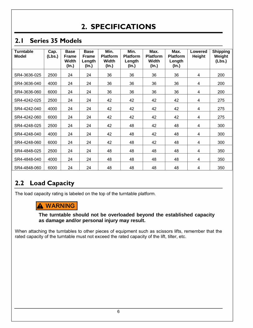
2.1 Series 35 Models
2.2 Load Capacity The load capacity rating is labeled on the top of the turntable platform.
The turntable should not be overloaded beyond the established capacity as damage and/or personal injury may result.
When attaching the turntables to other pieces of equipment such as scissors lifts, remember that the rated capacity of the turntable must not exceed the rated capacity of the lift, tilter, etc.
Turntable Model
Cap. (Lbs.)
Base Frame Width (In.)
Base Frame Length
(In.)
Min. Platform
Width (In.)
Min. Platform Length
(In.)
Max. Platform
Width (In.)
Max. Platform Length
(In.)
Lowered Height
Shipping Weight (Lbs.)
SR4-3636-025 2500 24 24 36 36 36 36 4 200
SR4-3636-040 4000 24 24 36 36 36 36 4 200
SR4-3636-060 6000 24 24 36 36 36 36 4 200
SR4-4242-025 2500 24 24 42 42 42 42 4 275
SR4-4242-040 4000 24 24 42 42 42 42 4 275
SR4-4242-060 6000 24 24 42 42 42 42 4 275
SR4-4248-025 2500 24 24 42 48 42 48 4 300
SR4-4248-040 4000 24 24 42 48 42 48 4 300
SR4-4248-060 6000 24 24 42 48 42 48 4 300
SR4-4848-025 2500 24 24 48 48 48 48 4 350
SR4-4848-040 4000 24 24 48 48 48 48 4 350
SR4-4848-060 6000 24 24 48 48 48 48 4 350
WARNING
7
2.3 Unbalanced Loading All standard turntable capacities assume that the load on the turntable is uniformly distributed and that the center of gravity of the load is placed within 10” of the center pin. Standard turntables are not designed to withstand true edge or axle loading. If edge or axle loading is anticipated, additional turntable support rollers must be located at the turntable edges. Contact Autoquip Service Department for questions on turntable loading.
Load the turntable top as evenly as possible to prevent overloading. Excessive eccentric loading may overstress the turntable structure and cause the load to become unstable, possibly resulting in serious personal injury or permanent equipment damage.
WARNING

8
3. SAFETY
3.1 Safety Signal Words This Owner’s Manual covers SR4 Manual Turntables produced by Autoquip. Before installing, operating or servicing turntable, you must read, understand and follow the instructions and safety warnings in this manual. Your turntable may not be equipped with some optional equipment shown in this manual. The safety information in this manual is denoted by the safety alert symbol: The level of risk is indicated by the following signal words.
DANGER – Indicates a hazardous situation, which, if not avoided, will result in death or serious injury.
WARNING – Indicates a hazardous situation, which, if not avoided, could result in death or serious injury.
CAUTION – Indicates a hazardous situation, which, if not avoided, could result in minor or moderate injury.
NOTICE – Indicates a situation that could result in damage to the turntable or other property.
3.2 Installation
The turntable base MUST be lagged securely to the floor or sufficient structure, or attached to a lift platform (when applicable) before operating the turntable. An unsecured base could become unstable and cause the load to shift unexpectedly resulting in serious personal injury or death.
Do not install the turntable in a pit unless it has beveled-toe guards or other approved toe protection. A shear point can exist which can cause severe personal injury.
DANGER
WARNING
CAUTION
NOTICE
DANGER
WARNING
9
3.3 Operation
Prevent serious injury or death. Load the turntable top as evenly as possible to prevent overloading. Excessive eccentric loading may overstress the turntable structure and cause the load to become unstable, possibly resulting in serious personal injury or permanent equipment damage. Overloading, or uneven loading, could result in load instability and cause serious personal injury. Stay clear of turntable while it is in motion. Never stand, sit or ride on turntable.
Prevent serious injury or death.
NEVER stand, sit, or ride on the turntable! A rotating work surface may shift position unexpectedly and cause serious personal injury.
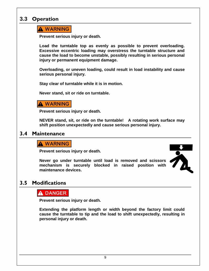
3.4 Maintenance
Prevent serious injury or death. Never go under turntable until load is removed and scissors mechanism is securely blocked in raised position with maintenance devices.
3.5 Modifications
Prevent serious injury or death.
Extending the platform length or width beyond the factory limit could cause the turntable to tip and the load to shift unexpectedly, resulting in personal injury or death.
WARNING
WARNING
WARNING
DANGER

10
3.6 Labels
Top of Turntable
A – 36401586
B – 36403706

11
36401560
To protect against death or serious injury, all labels must be on turntable and must be legible. If any of these labels are missing or cannot be read, call Autoquip for replacement labels.
WARNING

12
4. INSTALLATION
4.1 Floor Mounting
When moving the turntable assembly, do not pick up the turntable assembly by the turntable PLATFORM; it is attached to the turntable base and could be damaged. Pick up the turntable from under the Base Plate ONLY.
1. Verify the mounting surface is clean before starting. 2. Place the turntable base in the installation area. Set the turntable platform aside for now. 3. The base plate of the turntable has pre-drilled holes for lagging the turntable securely to the floor or
lift. Mark the holes, drill, and install with anchors. Verify that the surface that the turntable will be mounted on is of sufficient strength to support the loads.
The turntable base MUST be lagged securely to the floor or sufficient structure, or attached to a lift platform (when applicable) before operating the turntable. An unsecured base could become unstable and cause the load to shift unexpectedly resulting in serious personal injury or death.
4. Install the turntable platform to the turntable base plate as shown in Figure 1.
4.2 Lift Mounting – Operating Above Floor Level
When moving the turntable assembly, do not pick up the turntable assembly by the turntable PLATFORM; it is attached to the turntable base and could be damaged. Pick up the turntable from under the Base Plate ONLY.
1. Verify the mounting surface is clean before starting. 2. Center the turntable base on the lift platform. Remove the turntable center axle bolt and set the
turntable platform aside for now. NOTE: When removing the center axle bolt, note the position of the wasters for future re-assembly.
3. The base plate of the turntable has pre-drilled holes for attaching the turntable base securely to the
lift platform. Mark the turntable base mounting holes, drill, and attach with Class 2 ( or higher) hardware. The turntable base must be welded or bolted to the lift platform, if desired (See Figure 2).
NOTICE
DANGER
NOTICE
13
The turntable base MUST be lagged securely to the floor or sufficient structure, or attached to a lift platform (when applicable) before operating the turntable. An unsecured base could become unstable and cause the load to shift unexpectedly resulting in serious personal injury or death.
4. Install the turntable platform to the turntable base as shown in Figure 1.
4.3 Lift Mounting – Operating Above and Below Floor Level
When moving the turntable assembly, do not pick up the turntable assembly by the turntable PLATFORM; it is attached to the turntable base and could be damaged. Pick up the turntable from under the Base Plate ONLY.
1. Verify the mounting surface is clean before starting. 2. Center the turntable base on the lift platform. Set the turntable platform aside for now. 3. The base plate of the turntable has pre-drilled holes for attaching the turntable securely to the lift
platform. Mark the holes, drill, and attach with Class 2 (or higher) hardware. The turntable base may be welded to the lift platform, if desired (See Figure 2).
The turntable base MUST be bolted or welded securely to a lift platform before operating the turntable. An unsecured base could become unstable and cause the load to shift unexpectedly resulting in serious personal injury or death.
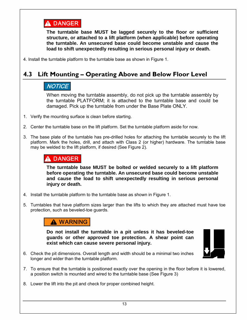
4. Install the turntable platform to the turntable base as shown in Figure 1. 5. Turntables that have platform sizes larger than the lifts to which they are attached must have toe
protection, such as beveled-toe guards.
Do not install the turntable in a pit unless it has beveled-toe guards or other approved toe protection. A shear point can exist which can cause severe personal injury.
6. Check the pit dimensions. Overall length and width should be a minimal two inches
longer and wider than the turntable platform. 7. To ensure that the turntable is positioned exactly over the opening in the floor before it is lowered,
a position switch is mounted and wired to the turntable base (See Figure 3)
8. Lower the lift into the pit and check for proper combined height.
DANGER
NOTICE
DANGER
WARNING
14
9. Position and adjust the platform in the pit making sure there is proper clearance (1” minimum around the edges from the platform to the pit angle).
10. Make the permanent electrical connections and operate the lift through a few cycles, ensuring that
the lift will not lower if the turntable platform is not in the proper position.
4.4 Clean Up 1. Clean up any debris from the area. A clean installation makes a good impression and creates a
much safer environment! 2. Touch-up paint may be purchased from Autoquip for repair of damaged paint surfaces.
All warning and information decals should be in place as outlined in the “Label Identification” section. If decals are missing or damaged, they should be replaced with new ones. Contact Autoquip for replacements.
WARNING

15
Figure 1

16
Figure 2

17
Figure 3
18
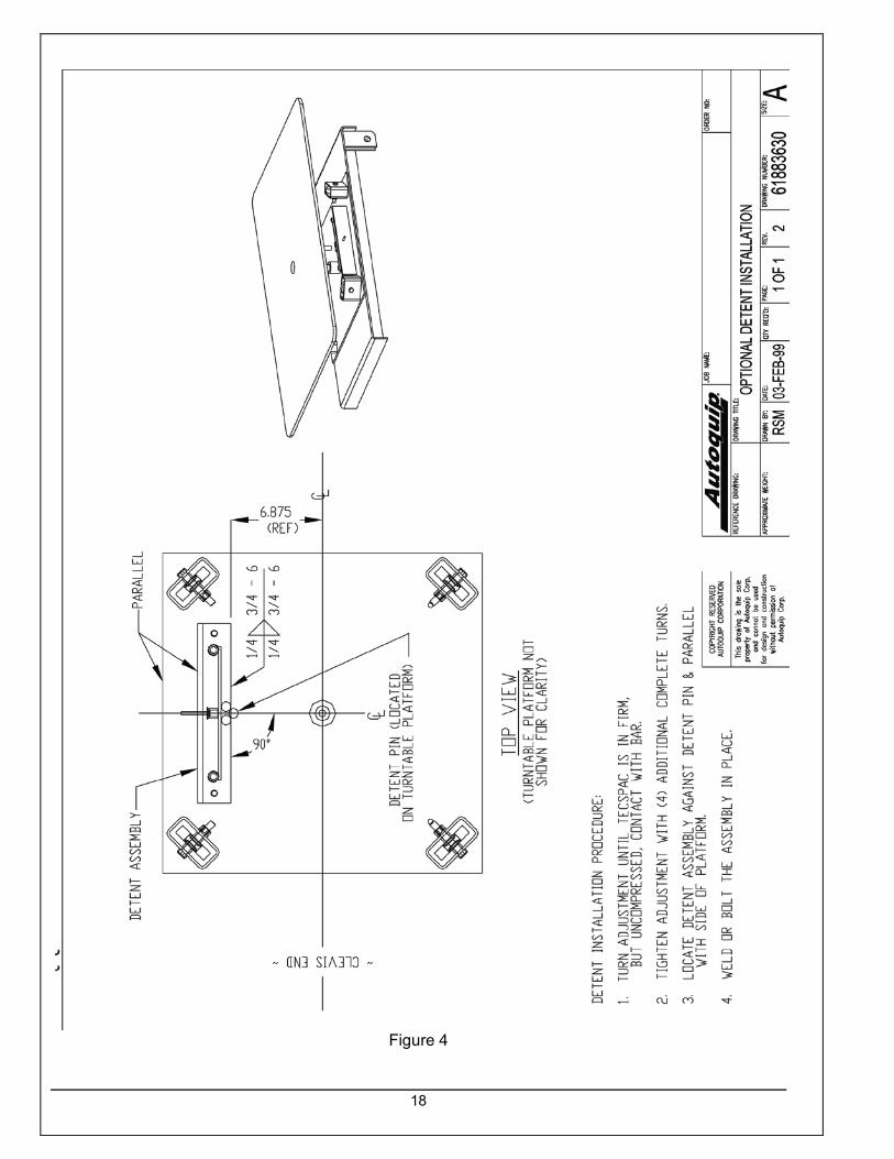
Figure 4

19
5. OPERATION
5.1 Operate Safely 1. Turntables have maximum capacities that vary depending on the model (See “Specifications”
section). Applying loads that exceed the rated capacity of the turntable may result in excessive wear and damage to the turntable as well as possible personal injury.
2. Always place the load as close as possible to the center of the turntable platform. Standard
turntables are designed to operate optimally with the center of gravity of the load within 10 inches of the center pin of the turntable.
3. The standard turntable is not designed to withstand high-point loads (pallet jacks or carts wheeled
onto the platform, conveyed loads rolling onto the platform, etc.) on the outside edge of the turntable platform. High-point loads will tip the platform to one inch or more. If the application involves edge loading, please contact the Autoquip Service Department to discuss possible solutions to prevent excessive platform tipping.
The turntable base MUST be lagged securely to the floor or sufficient structure, or attached to a lift platform (when applicable) before operating the turntable. An unsecured base could become unstable and cause the load to shift unexpectedly resulting in serious personal injury or death.
Load the turntable top as evenly as possible to prevent overloading. Excessive eccentric loading may overstress the turntable structure and cause the load to become unstable, possibly resulting in serious personal injury or permanent equipment damage.
NEVER stand, sit, or ride on the turntable! A rotating work surface may shift position unexpectedly and cause serious personal injury.
5.2 Forces Required to Operate Manual Turntable An evenly loaded 48” x 48” manual turntable has the following approximate starting and sustaining force requirements to rotate the loads shown by holding on to one of the platform corners:
Load Capacity (lbs) Starting Force (lbs) Sustaining Force (lbs) 1000 15 10 2000 20 15 3000 26 20 4000 32 26 5000 40 32 6000 48 40
These forces increase if the actual platform size is smaller than 48 x 48” or if the turntable is loaded unevenly
DANGER
WARNING
WARNING

20
6. MAINTENANCE
6.1 Routine Maintenance
6.1.1 Every Month Or 100 Hours Of Operation
NEVER go under a raised lift platform until load is removed and lift is securely blocked in raised position with maintenance devices. Lock-out/tag-out power source.
1. Check any unusual noise when it occurs. Determine the source and correct as necessary. 2. Check the hardware at all rollers, if not in place, and/or secure, replace or repair immediately. 3. Check all rollers and bearings for signs of wear. Replace as necessary.
WARNING

21

22
7. TROUBLESHOOTING
Prevent serious injury or death. Disconnect and/or lock out electrical supply to power unit prior to any maintenance being performed.
WARNING
PROBLEM POSSIBLE CAUSE AND SOLUTION Turntable is difficult to rotate There may be roller damage. Check the turntable base rollers
for proper alignment and possible bearing damage. Replace as necessary. The load is not evenly distributed on t he platform. Make sure that the center of gravity of the load is within 10” of the center of the turntable.
One or more roller tubes are not sitting vertically on the base plate. Make sure that each roller tube is perpendicular to the base plate (it could have been bent slightly during shipping/handling). Call the factory for base replacement. The thrust washers are not installed properly. See Figure 5 in the Installation Section to ensure that the center pin thrust washers have been installed properly. Missing washers will cause the platform to “dish” in the center when bolted in place. The center pin-retaining bolt has been over tightened. The retaining bolt should be backed off and retightened using no more than 80 ft. lbs of torque. If the turntable was provided with detents, the detent bar may be set too tight. There is an adjustment screw to lessen the stopping pressure against the detent pins.
Turntable is making a popping noise.
One or more roller tubes are misaligned with respect to the center pin. Each tube should be perpendicular to the center pin, or the platform will roll across the roller instead of rolling over it. Perpendicularity can be checked using a large square. Call the factory for base replacement.

23
8. PARTS PART NUMBER DESCRIPTION 52605060 Roller with Bearing 35106120 Bolt and Washer Kit for SR4 Turntable