INSTALLATION, OPERATION, AND MAINTENANCE...
116
Please record the following data for file reference Tag Number(s): _____________________________________ Model Number: _____________________________________ Serial Number: _____________________________________ Installation Date: ____________________________________ Installation Location: ________________________________ INSTALLATION, OPERATION, AND MAINTENANCE MANUAL EV1-Series Metering Pump 339-0091-000 ISSUED 10/2008 THIS MANUAL SUPERSEDES MANUAL OM/EV1 AND EV1 PARTS CATALOG DATED 11/2000. USE THIS MANUAL FOR SERIAL NUMBERS 2403816 AND ABOVE.
Transcript of INSTALLATION, OPERATION, AND MAINTENANCE...

Please record the following data for file reference
Tag Number(s): _____________________________________
Model Number: _____________________________________
Serial Number: _____________________________________
Installation Date: ____________________________________
Installation Location: ________________________________
INSTALLATION,OPERATION, ANDMAINTENANCEMANUAL
EV1-SeriesMetering Pump
339-0091-000ISSUED 10/2008
THIS MANUAL SUPERSEDES MANUAL OM/EV1AND EV1 PARTS CATALOG DATED 11/2000. USETHIS MANUAL FOR SERIAL NUMBERS 2403816AND ABOVE.


EV1
i
TABLE OF CONTENTS
TABLE OF CONTENTS . . . . . . . . . . . . . . . . . . . . . . . . . . . . . . . . . . . . . . . . . . . . . . . . . . . . . . . . . . . . . . . . i
MODEL/PRODUCT CODE . . . . . . . . . . . . . . . . . . . . . . . . . . . . . . . . . . . . . . . . . . . . . . . . . . . . . . . . . . . . .vi
DESCRIPTION . . . . . . . . . . . . . . . . . . . . . . . . . . . . . . . . . . . . . . . . . . . . . . . . . . . . . . . . . . . . . . . . . . . . . . 1
1.1 GENERAL INFORMATION . . . . . . . . . . . . . . . . . . . . . . . . . . . . . . . . . . . . . . . . . . . . . . . . . . . . . . 1
1.2 DRIVECASE ASSEMBLY . . . . . . . . . . . . . . . . . . . . . . . . . . . . . . . . . . . . . . . . . . . . . . . . . . . . . . . 2
1.3 LIQUID END ASSEMBLY . . . . . . . . . . . . . . . . . . . . . . . . . . . . . . . . . . . . . . . . . . . . . . . . . . . . . . . 2
1.4 PLUNGER BODY ASSEMBLY . . . . . . . . . . . . . . . . . . . . . . . . . . . . . . . . . . . . . . . . . . . . . . . . . . . 2
1.5 STROKE LENGTH ADJUSTMENT ASSEMBLY . . . . . . . . . . . . . . . . . . . . . . . . . . . . . . . . . . . . . 2
1.6 GENERAL SPECIFICATIONS . . . . . . . . . . . . . . . . . . . . . . . . . . . . . . . . . . . . . . . . . . . . . . . . . . . 2
SECTION 2 - INSTALLATION . . . . . . . . . . . . . . . . . . . . . . . . . . . . . . . . . . . . . . . . . . . . . . . . . . . . . . . . . . 3
2.1 UNPACKING . . . . . . . . . . . . . . . . . . . . . . . . . . . . . . . . . . . . . . . . . . . . . . . . . . . . . . . . . . . . . . . . . 3
2.2 STORAGE . . . . . . . . . . . . . . . . . . . . . . . . . . . . . . . . . . . . . . . . . . . . . . . . . . . . . . . . . . . . . . . . . . . 3
2.3 SAFETY PRECAUTIONS . . . . . . . . . . . . . . . . . . . . . . . . . . . . . . . . . . . . . . . . . . . . . . . . . . . . . . . 4
2.4 MOUNTING . . . . . . . . . . . . . . . . . . . . . . . . . . . . . . . . . . . . . . . . . . . . . . . . . . . . . . . . . . . . . . . . . . 4
2.5 DRIP COLLECTION . . . . . . . . . . . . . . . . . . . . . . . . . . . . . . . . . . . . . . . . . . . . . . . . . . . . . . . . . . . 4
2.6 PIPING. . . . . . . . . . . . . . . . . . . . . . . . . . . . . . . . . . . . . . . . . . . . . . . . . . . . . . . . . . . . . . . . . . . . . . 4
2.6.1 General Piping Considerations . . . . . . . . . . . . . . . . . . . . . . . . . . . . . . . . . . . . . . . . . . . . 4
2.6.2 Suction Piping Considerations . . . . . . . . . . . . . . . . . . . . . . . . . . . . . . . . . . . . . . . . . . . . 5
2.6.3 Discharge Piping Considerations . . . . . . . . . . . . . . . . . . . . . . . . . . . . . . . . . . . . . . . . . . 5
2.7 VALVES. . . . . . . . . . . . . . . . . . . . . . . . . . . . . . . . . . . . . . . . . . . . . . . . . . . . . . . . . . . . . . . . . . . . . 5
2.7.1 Back Pressure Valves . . . . . . . . . . . . . . . . . . . . . . . . . . . . . . . . . . . . . . . . . . . . . . . . . . . . 5
2.7.2 Pulsation Dampeners . . . . . . . . . . . . . . . . . . . . . . . . . . . . . . . . . . . . . . . . . . . . . . . . . . . . 6
2.7.3 Safety Valves and Priming Valves . . . . . . . . . . . . . . . . . . . . . . . . . . . . . . . . . . . . . . . . . . 6
2.7.4 Shut-off Valves. . . . . . . . . . . . . . . . . . . . . . . . . . . . . . . . . . . . . . . . . . . . . . . . . . . . . . . . . . 6
2.8 ELECTRICAL CONNECTIONS. . . . . . . . . . . . . . . . . . . . . . . . . . . . . . . . . . . . . . . . . . . . . . . . . . . 6
SECTION 3 - OPERATION . . . . . . . . . . . . . . . . . . . . . . . . . . . . . . . . . . . . . . . . . . . . . . . . . . . . . . . . . . . . . 7
3.1 RECOMMENDED LUBRICATION . . . . . . . . . . . . . . . . . . . . . . . . . . . . . . . . . . . . . . . . . . . . . . . . 7
3.2 START-UP CHECKS. . . . . . . . . . . . . . . . . . . . . . . . . . . . . . . . . . . . . . . . . . . . . . . . . . . . . . . . . . . 7
3.3 NPSH . . . . . . . . . . . . . . . . . . . . . . . . . . . . . . . . . . . . . . . . . . . . . . . . . . . . . . . . . . . . . . . . . . . . . . . 7
3.4 BACK PRESSURE . . . . . . . . . . . . . . . . . . . . . . . . . . . . . . . . . . . . . . . . . . . . . . . . . . . . . . . . . . . . 7

EV1
ii
3.5 START-UP . . . . . . . . . . . . . . . . . . . . . . . . . . . . . . . . . . . . . . . . . . . . . . . . . . . . . . . . . . . . . . . . . . . 7
3.6 FLOW RATE ADJUSTMENT . . . . . . . . . . . . . . . . . . . . . . . . . . . . . . . . . . . . . . . . . . . . . . . . . . . . 8
3.7 CALIBRATION . . . . . . . . . . . . . . . . . . . . . . . . . . . . . . . . . . . . . . . . . . . . . . . . . . . . . . . . . . . . . . . 8
3.8 HYDRAULIC PRIMING . . . . . . . . . . . . . . . . . . . . . . . . . . . . . . . . . . . . . . . . . . . . . . . . . . . . . . . . . 8
3.9 RELIEF VALVE SETTING. . . . . . . . . . . . . . . . . . . . . . . . . . . . . . . . . . . . . . . . . . . . . . . . . . . . . . . 8
3.10 TROUBLESHOOTING. . . . . . . . . . . . . . . . . . . . . . . . . . . . . . . . . . . . . . . . . . . . . . . . . . . . . . . . . 9
3.11 TOOLS & WORKING FACILITY . . . . . . . . . . . . . . . . . . . . . . . . . . . . . . . . . . . . . . . . . . . . . . . . . 9
SECTION 4 - MAINTENANCE . . . . . . . . . . . . . . . . . . . . . . . . . . . . . . . . . . . . . . . . . . . . . . . . . . . . . . . . . 11
4.1 ROUTINE MAINTENANCE . . . . . . . . . . . . . . . . . . . . . . . . . . . . . . . . . . . . . . . . . . . . . . . . . . . . . 11
4.2 SPARE PARTS . . . . . . . . . . . . . . . . . . . . . . . . . . . . . . . . . . . . . . . . . . . . . . . . . . . . . . . . . . . . . . 11
4.3 DRIVE MOTOR (FIGURE 3) . . . . . . . . . . . . . . . . . . . . . . . . . . . . . . . . . . . . . . . . . . . . . . . . . . . . 11
4.4 CHECK VALVES. . . . . . . . . . . . . . . . . . . . . . . . . . . . . . . . . . . . . . . . . . . . . . . . . . . . . . . . . . . . . 12
4.5 LIQUID END ASSSEMBLY . . . . . . . . . . . . . . . . . . . . . . . . . . . . . . . . . . . . . . . . . . . . . . . . . . . . . 14
4.6 PLUNGER BODY ASSSEMBLY . . . . . . . . . . . . . . . . . . . . . . . . . . . . . . . . . . . . . . . . . . . . . . . . . 15
4.7 STROKE LENGTH ADJUSTMENT ASSSEMBLY . . . . . . . . . . . . . . . . . . . . . . . . . . . . . . . . . . . 19
4.8 ELECTRONIC ACTUATOR ALIGNMENT PROCEDURE . . . . . . . . . . . . . . . . . . . . . . . . . . . . . 21
4.9 MOTOR ADAPTER/ECCENTRIC SHAFT ASSEMBLY . . . . . . . . . . . . . . . . . . . . . . . . . . . . . . . 23
4.10 DRIVE CASE ASSSEMBLY . . . . . . . . . . . . . . . . . . . . . . . . . . . . . . . . . . . . . . . . . . . . . . . . . . . 24
4.11 MULTIPLEX. . . . . . . . . . . . . . . . . . . . . . . . . . . . . . . . . . . . . . . . . . . . . . . . . . . . . . . . . . . . . . . . 25
4.12 LEAK DETECTION (OPTIONAL) . . . . . . . . . . . . . . . . . . . . . . . . . . . . . . . . . . . . . . . . . . . . . . . 26
4.12.1 Introduction . . . . . . . . . . . . . . . . . . . . . . . . . . . . . . . . . . . . . . . . . . . . . . . . . . . . . . . . . 26
4.12.2 Specifications. . . . . . . . . . . . . . . . . . . . . . . . . . . . . . . . . . . . . . . . . . . . . . . . . . . . . . . . 27
4.12.3 Pressure Switch . . . . . . . . . . . . . . . . . . . . . . . . . . . . . . . . . . . . . . . . . . . . . . . . . . . . . . 27
4.12.4 Wiring . . . . . . . . . . . . . . . . . . . . . . . . . . . . . . . . . . . . . . . . . . . . . . . . . . . . . . . . . . . . . . 30
4.12.5 Operation . . . . . . . . . . . . . . . . . . . . . . . . . . . . . . . . . . . . . . . . . . . . . . . . . . . . . . . . . . . 30
4.12.6 Start Up . . . . . . . . . . . . . . . . . . . . . . . . . . . . . . . . . . . . . . . . . . . . . . . . . . . . . . . . . . . . . 31
4.12.7 Conversion . . . . . . . . . . . . . . . . . . . . . . . . . . . . . . . . . . . . . . . . . . . . . . . . . . . . . . . . . . 31
4.12.8 Calibration . . . . . . . . . . . . . . . . . . . . . . . . . . . . . . . . . . . . . . . . . . . . . . . . . . . . . . . . . . 33
4.13 EVP PULSE-LESS OPTION . . . . . . . . . . . . . . . . . . . . . . . . . . . . . . . . . . . . . . . . . . . . . . . . . . . 35
4.13.1 Introduction . . . . . . . . . . . . . . . . . . . . . . . . . . . . . . . . . . . . . . . . . . . . . . . . . . . . . . . . . 35
4.13.2 Installation . . . . . . . . . . . . . . . . . . . . . . . . . . . . . . . . . . . . . . . . . . . . . . . . . . . . . . . . . . 35
4.13.3 Operation . . . . . . . . . . . . . . . . . . . . . . . . . . . . . . . . . . . . . . . . . . . . . . . . . . . . . . . . . . . 35

EV1
iii
4.13.4 Maintenance . . . . . . . . . . . . . . . . . . . . . . . . . . . . . . . . . . . . . . . . . . . . . . . . . . . . . . . . . 35
4.13.5 Plunger Assembly . . . . . . . . . . . . . . . . . . . . . . . . . . . . . . . . . . . . . . . . . . . . . . . . . . . . 35
4.13.6 Cam Assembly . . . . . . . . . . . . . . . . . . . . . . . . . . . . . . . . . . . . . . . . . . . . . . . . . . . . . . . 36
SECTION 5 - TROUBLESHOOTING . . . . . . . . . . . . . . . . . . . . . . . . . . . . . . . . . . . . . . . . . . . . . . . . . . . . 39
SECTION 6 - PARTS LIST . . . . . . . . . . . . . . . . . . . . . . . . . . . . . . . . . . . . . . . . . . . . . . . . . . . . . . . . . . . . 42
6.1 GENERAL . . . . . . . . . . . . . . . . . . . . . . . . . . . . . . . . . . . . . . . . . . . . . . . . . . . . . . . . . . . . . . . . . . 42
6.2 ILLUSTRATED PARTS LIST . . . . . . . . . . . . . . . . . . . . . . . . . . . . . . . . . . . . . . . . . . . . . . . . . . . 42
6.3 LIQUID END ASSEMBLY COMPONENTS, SIZE A (316SS, ALLOY 20, HAST C, PVC, & KYNAR) . . . . . . . . . . . . . . . . . . . . . . . . . . . . . . . . . . . . . . . . . . . . . . . . . . . . . . . . . . . . . . . . . . . . 45
6.4 LIQUID END ASSEMBLY, SIZE A . . . . . . . . . . . . . . . . . . . . . . . . . . . . . . . . . . . . . . . . . . . . . . . 46
6.5 METALLIC/PLASTIC REBUILD KIT, SIZE A . . . . . . . . . . . . . . . . . . . . . . . . . . . . . . . . . . . . . . . 48
6.6 METALLIC LEAK DETECTION, SIZE A (316SS, ALLOY 20, HAST C) . . . . . . . . . . . . . . . . . . 50
6.7 NON-METALLIC LEAK DETECTION, SIZE A (PVC, & KYNAR) . . . . . . . . . . . . . . . . . . . . . . . 52
6.8 PLUNGER BODY ASSEMBLY COMPONENTS, SIZE A. . . . . . . . . . . . . . . . . . . . . . . . . . . . . . 54
6.9 INTERNAL HYDRAULIC SUBASSEMBLIES, SIZE A . . . . . . . . . . . . . . . . . . . . . . . . . . . . . . . 57
6.10 PLUNGER BODY ASSEMBLIES, SIZE A . . . . . . . . . . . . . . . . . . . . . . . . . . . . . . . . . . . . . . . . 59
6.11 LIQUID END ASSEMBLY COMPONENTS, SIZE B (316SS, ALLOY 20, HAST C, PVC, & KYNAR) . . . . . . . . . . . . . . . . . . . . . . . . . . . . . . . . . . . . . . . . . . . . . . . . . . . . . . . . . . . . . . . . . . . . 63
6.12 LIQUID END ASSEMBLY, SIZE B . . . . . . . . . . . . . . . . . . . . . . . . . . . . . . . . . . . . . . . . . . . . . . 65
6.13 METALLIC/PLASTIC REBUILD KIT, SIZE B . . . . . . . . . . . . . . . . . . . . . . . . . . . . . . . . . . . . . . 67
6.14 LIQUID END ASSEMBLY COMPONENTS, SIZE C (316SS, ALLOY 20, HAST C, PVC, & KYNAR) . . . . . . . . . . . . . . . . . . . . . . . . . . . . . . . . . . . . . . . . . . . . . . . . . . . . . . . . . . . . . . . . . . . . 71
6.15 LIQUID END ASSEMBLY, SIZE C . . . . . . . . . . . . . . . . . . . . . . . . . . . . . . . . . . . . . . . . . . . . . . 73
6.16 METALLIC/PLASTIC REBUILD KIT, SIZE C . . . . . . . . . . . . . . . . . . . . . . . . . . . . . . . . . . . . . . 75
6.17 METALLIC LEAK DETECTION, SIZE B & C (316SS, ALLOY 20, HAST C) . . . . . . . . . . . . . 78
6.18 NON-METALLIC LEAK DETECTION, SIZE B & C (PVC, & KYNAR) . . . . . . . . . . . . . . . . . . . 80
6.19 PLUNGER BODY ASSEMBLY COMPONENTS, SIZE B & C . . . . . . . . . . . . . . . . . . . . . . . . . 82
6.20 PLUNGER INTERNAL HYDRAULIC SUBASSEMBLIES, SIZE B & C . . . . . . . . . . . . . . . . . . 85
6.21 PLUNGER BODY ASSEMBLIES, SIZE B & C . . . . . . . . . . . . . . . . . . . . . . . . . . . . . . . . . . . . . 87
6.22 MANUAL STROKE ADJUSTER ASSEMBLY . . . . . . . . . . . . . . . . . . . . . . . . . . . . . . . . . . . . . 90
6.23 ELECTRONIC STROKE ADJUSTER ASSEMBLY. . . . . . . . . . . . . . . . . . . . . . . . . . . . . . . . . . 92
6.24 MOTOR ADAPTER ASSY AND ECCENTRIC SHAFT / GEAR HUB ASSY . . . . . . . . . . . . . . 96
6.25 COVERS, DRIVECASE & MULTIPLEX PUMP ACCESSORIES . . . . . . . . . . . . . . . . . . . . . . 101

EV1
iv
FIGURES
FIGURE 1. EV1 Modular Metering Pump. . . . . . . . . . . . . . . . . . . . . . . . . . . . . . . . . . . . . . . . . . . .1FIGURE 2. Typical Piping Diagram . . . . . . . . . . . . . . . . . . . . . . . . . . . . . . . . . . . . . . . . . . . . . . . .7FIGURE 3. Drive Motor . . . . . . . . . . . . . . . . . . . . . . . . . . . . . . . . . . . . . . . . . . . . . . . . . . . . . . . . .11FIGURE 4. Metallic/Plastic, Head Assembly, Size A . . . . . . . . . . . . . . . . . . . . . . . . . . . . . . . . .12FIGURE 5. Metallic Head Assembly, Size B . . . . . . . . . . . . . . . . . . . . . . . . . . . . . . . . . . . . . . . .12FIGURE 6. Plastic, Head Assembly, Size B. . . . . . . . . . . . . . . . . . . . . . . . . . . . . . . . . . . . . . . . .13FIGURE 7. Metallic Head Assembly, Size C . . . . . . . . . . . . . . . . . . . . . . . . . . . . . . . . . . . . . . . .13FIGURE 8. Plastic, Head Assembly, Size C. . . . . . . . . . . . . . . . . . . . . . . . . . . . . . . . . . . . . . . . .14FIGURE 9. Breakaway of Size C Plastic Liquid End . . . . . . . . . . . . . . . . . . . . . . . . . . . . . . . . .14FIGURE 10. Breakaway of Size A Metalic Liquid End . . . . . . . . . . . . . . . . . . . . . . . . . . . . . . . . .14FIGURE 11. Plunger Seal . . . . . . . . . . . . . . . . . . . . . . . . . . . . . . . . . . . . . . . . . . . . . . . . . . . . . . . .15FIGURE 12. Plunger Body Assembly (Size B and C). . . . . . . . . . . . . . . . . . . . . . . . . . . . . . . . . .16FIGURE 13. Replenishment Check Assembly . . . . . . . . . . . . . . . . . . . . . . . . . . . . . . . . . . . . . . .17FIGURE 14. Pressure Relief/Air Bleed Assembly (Size B and C) . . . . . . . . . . . . . . . . . . . . . . . .18FIGURE 15. Replenishment Valve Assembly (Size B and C) . . . . . . . . . . . . . . . . . . . . . . . . . . .18FIGURE 16A. Replenishment Valve Hole. . . . . . . . . . . . . . . . . . . . . . . . . . . . . . . . . . . . . . . . . . . . .18FIGURE 16B. Plunger Body Hole . . . . . . . . . . . . . . . . . . . . . . . . . . . . . . . . . . . . . . . . . . . . . . . . . . .18FIGURE 16C. Plunger with Replenishment Valve and Rear Contour Plate Installed . . . . . . . . .19FIGURE 17. Stroke Adjuster Housing . . . . . . . . . . . . . . . . . . . . . . . . . . . . . . . . . . . . . . . . . . . . . .19FIGURE 18 Manual Stroke Adjuster . . . . . . . . . . . . . . . . . . . . . . . . . . . . . . . . . . . . . . . . . . . . . . .20FIGURE 19. Stroke Adjuster Assembly. . . . . . . . . . . . . . . . . . . . . . . . . . . . . . . . . . . . . . . . . . . . .20FIGURE 20 Wiring Diagram. . . . . . . . . . . . . . . . . . . . . . . . . . . . . . . . . . . . . . . . . . . . . . . . . . . . . .21FIGURE 21. Upper PC Board . . . . . . . . . . . . . . . . . . . . . . . . . . . . . . . . . . . . . . . . . . . . . . . . . . . . .21FIGURE 22. Dip Switch Configuration . . . . . . . . . . . . . . . . . . . . . . . . . . . . . . . . . . . . . . . . . . . . .22FIGURE 23. Pump View . . . . . . . . . . . . . . . . . . . . . . . . . . . . . . . . . . . . . . . . . . . . . . . . . . . . . . . . .22FIGURE 24. Lower PC Board . . . . . . . . . . . . . . . . . . . . . . . . . . . . . . . . . . . . . . . . . . . . . . . . . . . . .23FIGURE 25. Speed/Torque Curve. . . . . . . . . . . . . . . . . . . . . . . . . . . . . . . . . . . . . . . . . . . . . . . . . .23FIGURE 26. Motor Adapter/Eccentric Shaft Assembly . . . . . . . . . . . . . . . . . . . . . . . . . . . . . . . .24FIGURE 27. Drivecase . . . . . . . . . . . . . . . . . . . . . . . . . . . . . . . . . . . . . . . . . . . . . . . . . . . . . . . . . .25FIGURE 28. Multiplex . . . . . . . . . . . . . . . . . . . . . . . . . . . . . . . . . . . . . . . . . . . . . . . . . . . . . . . . . . .26FIGURE 29. Pressure Switch . . . . . . . . . . . . . . . . . . . . . . . . . . . . . . . . . . . . . . . . . . . . . . . . . . . . .27FIGURE 30. Pressure Switch Dimensions . . . . . . . . . . . . . . . . . . . . . . . . . . . . . . . . . . . . . . . . . .29FIGURE 31. Optic Probe . . . . . . . . . . . . . . . . . . . . . . . . . . . . . . . . . . . . . . . . . . . . . . . . . . . . . . . . .30FIGURE 32. Reaction Time vs Pressure . . . . . . . . . . . . . . . . . . . . . . . . . . . . . . . . . . . . . . . . . . . .30FIGURE 33. Diaphragm Assembly. . . . . . . . . . . . . . . . . . . . . . . . . . . . . . . . . . . . . . . . . . . . . . . . .32FIGURE 34. Metallic Leak Detection . . . . . . . . . . . . . . . . . . . . . . . . . . . . . . . . . . . . . . . . . . . . . . .33FIGURE 35. Non-Metallic Leak Detection . . . . . . . . . . . . . . . . . . . . . . . . . . . . . . . . . . . . . . . . . . .34FIGURE 36. Drivecase Assembly/Pulseless Cam Assembly . . . . . . . . . . . . . . . . . . . . . . . . . . .36FIGURE 37. Pulse-less Plunger Assembly . . . . . . . . . . . . . . . . . . . . . . . . . . . . . . . . . . . . . . . . . .37FIGURE 38. EV1 Cross Sectional . . . . . . . . . . . . . . . . . . . . . . . . . . . . . . . . . . . . . . . . . . . . . . . . .38FIGURE 39. Liquid End Assembly, Size A . . . . . . . . . . . . . . . . . . . . . . . . . . . . . . . . . . . . . . . . . .44FIGURE 40. Metallic/Plastic Rebuild kit, Size A . . . . . . . . . . . . . . . . . . . . . . . . . . . . . . . . . . . . . .47FIGURE 41. Metallic Leak Detection, Size A . . . . . . . . . . . . . . . . . . . . . . . . . . . . . . . . . . . . . . . . .49FIGURE 42. Non-Metallic Leak Detection, Size A. . . . . . . . . . . . . . . . . . . . . . . . . . . . . . . . . . . . .51

EV1
v
FIGURE 43. Plunger Body Assembly, Size A . . . . . . . . . . . . . . . . . . . . . . . . . . . . . . . . . . . . . . . .53FIGURE 44. Internal Hydraulic Subassemblies, Size A . . . . . . . . . . . . . . . . . . . . . . . . . . . . . . . .56FIGURE 45. Liquid End Assembly, Size B, Metallic . . . . . . . . . . . . . . . . . . . . . . . . . . . . . . . . . . .61FIGURE 46. Liquid End Assembly, Size B, Non-Metallic . . . . . . . . . . . . . . . . . . . . . . . . . . . . . . .62FIGURE 47. Metallic/Plastic Rebuild kit, Size B . . . . . . . . . . . . . . . . . . . . . . . . . . . . . . . . . . . . . .66FIGURE 48. Liquid End Assembly, SizeC, Metallic . . . . . . . . . . . . . . . . . . . . . . . . . . . . . . . . . . .69FIGURE 49. Liquid End Assembly, Size C, Non-Metallic . . . . . . . . . . . . . . . . . . . . . . . . . . . . . . .70FIGURE 50. Metallic/Plastic Rebuild kit, Size C . . . . . . . . . . . . . . . . . . . . . . . . . . . . . . . . . . . . . .74FIGURE 51. Metallic Leak Detection, Size B & C . . . . . . . . . . . . . . . . . . . . . . . . . . . . . . . . . . . . .77FIGURE 52. Non-Metallic Leak Detection, Size B & C . . . . . . . . . . . . . . . . . . . . . . . . . . . . . . . . .79FIGURE 53. Plunger Body Assembly, Size B & C . . . . . . . . . . . . . . . . . . . . . . . . . . . . . . . . . . . .81FIGURE 54. Plunger Body Internal Hydraulic Subassemblies, Size B & C . . . . . . . . . . . . . . . .84FIGURE 55. Manual Stroke Adjuster Assembly . . . . . . . . . . . . . . . . . . . . . . . . . . . . . . . . . . . . . .89FIGURE 56. Electronic Stroke Adjuster Assembly . . . . . . . . . . . . . . . . . . . . . . . . . . . . . . . . . . .91FIGURE 57. Motor Adapter Assembly (Direct Mount) . . . . . . . . . . . . . . . . . . . . . . . . . . . . . . . . .94FIGURE 58. Eccentric Shaft / Gear Hub Assembly . . . . . . . . . . . . . . . . . . . . . . . . . . . . . . . . . . .94FIGURE 59. Motor Adapter Assembly (Flexible Coupling Mount) . . . . . . . . . . . . . . . . . . . . . . .95FIGURE 60. Covers, Drivecase & Multiplex Pump Accessories. . . . . . . . . . . . . . . . . . . . . . . . 100
EV1
vi

EV1
1
SECTION 1DESCRIPTION
1.1 GENERAL INFORMATION
The Milton Roy EV1 pump is a product designed tofill most industries' metering application needs.This has been accomplished with proven technol-ogy used in new and innovative ways. Through ourengineering program, we have optimized eachcomponent for safety, functionality, durability, andeconomy. These guidelines and the AmericanPetroleum Institutes' API 675 Standards were usedas a goal.
Fully encased check valve assemblies with cap-tured PTFE seals and internal hydraulic relief sys-tem assures safe operation. Pump performance isenhanced by eliminating the liquid end contourplate. This is accomplished by using a demandtype hydraulic system. The benefits of this design
are superior slurry and viscous handling capabili-ties, increased diaphragm life, and greater lift capa-bilities. Accuracy is improved through the use of afinely calibrated stroke adjuster, integral hydraulicrelief / air bleed system and aerospace qualityplunger seal. Through the use of a cast iron drive-case, hardened steel wear surfaces, anti-frictionbearing with high L-10 life, and gearing with AGMAservice factors, the EV1 is designed for low mainte-nance, long life operation. By using rigid standardsfor quality, workmanship, and product design, theEV1 has proven to be an economical investment.
Additionally the EV1 is based on a modular design.The metering pump has four independent assem-blies as illustrated in Figure 1.
1.2 DRIVECASE ASSEMBLY
Figure 1. EV1 Modular Metering Pump.

EV1
2
The heavy-duty construction furnishes strengthand durability. The symmetrical design permits oneor two feeds as in our duplex pumps. And multi-plexing allows as many as 12 feeds with onemotor. The drivecase accept NEMA 56C and IECmotor frames.
1.3 LIQUID END ASSEMBLY
The liquid end uses a single diaphragm design,without a process side contour plate. Positive seal-ing ball check valves create the pumping action.Check valves can be easily replaced or rebuilt inthe field. Standard wet end materials include 316stainless steel, Alloy 20, Hastelloy C, PVC, andPVDF.
1.4 PLUNGER BODY ASSEMBLY
Milton Roy provides a reciprocating plunger designthat features a 3/4 inch (19 mm) stroke length andeight interchangeable plunger sizes (See Model/Product code located prior to Section one).
A field replaceable, three-part plunger seal pro-vides the wear surface between the plungerassembly and the plunger.
A filter eliminates any contaminants from enteringthe pump’s plunger system.
Air from the pressurized plunger system is ventedthrough an externally adjustable relief valve poppetlocated at the high point of the plunger system.
A replenishment valve/replenishment check worktogether to insure excellent suction lift.
1.5 STROKE LENGTH ADJUSTMENT ASSEM-BLY
The stroke length is fully adjustable from 0% to100% in 1% increments. The adjuster is fullysealed to prevent contamination or oil leakage.Also the stroke adjuster can be easily converted toan electronic stroke adjuster.
1.6 GENERAL SPECIFICATIONS
Flow Rate:
0.08 GPH (0.30 L/H) to 220 GPH (833 L/H)
Pressure:
Up to 3500 PSIG (241 BAR)
Turn Down Ratio:
10:1 (optional 100:1)
Steady State Accuracy:
±0.5% of flow setting
Repeatability:
± 2% of full flow
Linearity:
± 1% of full flow
Maximum Temperature:
Metallic to 250 F (121 C)
Non-metallic to 150 F (66 C)
Paint:
Power Coating
° °
° °

EV1
3
SECTION 2INSTALLATION
2.1 UNPACKING
Pumps are shipped f.o.b. factory or representativewarehouse and the title passes to the customerwhen the carrier signs for receipt of the pump. Inthe event that damages occur during shipment, it isthe responsibility of the customer to notify the car-rier immediately and to file a damage claim. Care-fully examine the shipping crate upon receipt fromthe carrier to be sure there is no obvious damageto the contents. Open the crate carefully so acces-sory items fastened to the inside of the crate willnot be damaged or lost. Examine all materialinside the crate and check against packing list tobe sure that all items are accounted for and intact.
2.2 STORAGE
Short Term Storage (Less than 6 Months)
It is preferable to store the material under a shelterin its original package to protect it from adverseweather conditions. In condensing atmospheres,follow the long term storage procedure.
Long Term Storage (Longer than 6 Months)
The primary consideration in storage of pumpequipment is to prevent corrosion of external andinternal components. This corrosion is caused bynatural circulation of air as temperature of the sur-roundings change from day to night, day to day,and from season to season. It is not practical toprevent this circulation which carries water vaporand other corrosive gasses, so it is necessary toprotect internal and external surfaces from theireffects to the greatest extent possible.
When the instructions given in this section arecompleted, the equipment is to be stored in a shel-ter; protected from direct exposure to weather. Theprepared equipment should be covered with aplastic sheet or a tarpaulin, but in a manner whichwill allow air circulation and prevent capture ofmoisture. Equipment should be stored 12 inchesor more above the ground.
If equipment is to be shipped directly from MiltonRoy into long term storage, contact Milton Roy toarrange for factory preparation.
Pump Drive and Gearbox
1. Flood the gearbox compartment with a highgrade lubricating oil/rust preventative such asMobile Oil Corporation product Mobilarma 524. Fillthe compartment completely to minimize air spaceand water vapor condensation. After storage,drain this material and refill the equipment with therecommended operating lubricant for equipmentcommissioning.
2. Remove drive motors and mounting adapters,and brush all unpainted metal surfaces with multi-purpose grease (NLGI grade 2 or 3). Store theseunattached.
Pump Liquid Ends
1. Flood the front compartment of the pump hous-ing with a high grade Lubricating Oil/Rust Preven-tative such as Mobil Oil Corporation product“Mobilarma 527”. Fill the pump-housing compart-ment all the way to minimize airspace and watervapor condensation.
2. Most of the liquid ends are constructed of inher-ently corrosion resistant materials and require noapplied corrosion inhibitor. If they are NOT natu-rally resistant (test the threaded or flanged inletand outlet connections - if they have little or nomagnetic property, they are resistant) they shouldbe flush filled with a corrosion inhibiting and non-freezing liquid which is compatible with the finalpumped process chemical. Flush and fill with inhib-itors such as “Mobilarma 524” or with a commercialautomotive antifreeze coolant. The pump liquid endcontains one way check valves, so flush in a direc-tion into the suction (bottom) connection, and outthe discharge (to) connection.
3. Cap or plug all openings to capture the inhibitingfluid, and to prevent animals and insects frombuilding nests.
Pneumatic, Electrical and Electronic Equip-ment
1. Motors should be prepared in the manner pre-scribed by their manufacturer. If information is notavailable, dismount and store motors as indicatedin step 3 below.

EV1
4
2. Dismount electrical equipment (includingmotors) from the pump.
3. For all pneumatic and electrical equipment,place packets of Vapor Phase Corrosion Inhibitor(VPCI) inside of the enclosure, then place theentire enclosure, with additional packets, inside aplastic bag. Seal the bag tightly closed. ContactMilton Roy Service Department for recommendedVPCI materials.
2.3 SAFETY PRECAUTIONS
WARNINGWHEN INSTALLING, OPERATING, ANDMAINTAINING THIS EV1 PUMP, KEEPSAFETY CONSIDERATIONS FORE-MOST. USE PROPER TOOLS,PROTECTIVE CLOTHING, AND EYEPROTECTION WHEN WORKING ONTHE EQUIPMENT AND INSTALL THEEQUIPMENT WITH A VIEW TOWARDENSURING SAFE OPERATION.FOLLOW THE INSTRUCTIONS IN THISMANUAL AND TAKE ADDITIONALSAFETY MEASURES APPROPRIATETO THE LIQUID BEING PUMPED. BEEXTREMELY CAREFUL IN THEPRESENCE OF HAZARDOUSSUBSTANCES (E.G., CORROSIVES,TOXINS, SOLVENTS, ACIDS,CAUSTICS, FLAMMABLES, ETC.).
THE PERSONNEL RESPONSIBLE FORINSTALLATION, OPERATION ANDMAINTENANCE OF THIS EQUIPMENTMUST BECOME FULLY ACQUAINTEDWITH THE CONTENTS OF THIS MAN-UAL.
ANY SERVICING OF THIS EQUIPMENTMUST BE CARRIED OUT WHEN THEUNIT IS STOPPED AND ALL PRES-SURE HAS BEEN BLED FROM THE LIQ-UID END. SHUT-OFF VALVES INSUCTION AND DISCHARGE SIDES OFTHE LIQUID END SHOULD BE CLOSEDWHILE THE UNIT IS BEING SER-
VICED. ACTIONS SHOULD BE TAKENTO ELIMINATE THE POSSIBILITY OFACCIDENTAL START-UP WHILE SER-VICING IS TAKING PLACE. A NOTICESHOULD BE POSTED BY THE POWERSWITCH TO WARN THAT SERVICING ISBEING CARRIED OUT ON THE EQUIP-MENT. SWITCH OFF THE POWER SUP-PLY AS SOON AS ANY FAULT ISDETECTED DURING OPERATION(EXAMPLES: ABNORMALLY HIGHDRIVE TEMPERATURE, UNUSUALNOISE, DIAPHRAGM FAILURE).
2.4 MOUNTING
Milton Roy metering pumps are designed to oper-ate in harsh indoor and outdoor services. Areas ofservice, however, may affect motor or accessoryspecifications, unless properly selected. Therefore,Milton Roy recommends that pumps installed out-doors be protected by a shelter.
Support the pump firmly in a level position using 4,grade 5 bolts on a solid, vibration-free foundation.The pump should preferably be positioned with thebase above floor level to protect the pump fromwash downs and to provide easier access for ser-vice. Be sure to allow enough space around thepump for easy access during maintenance opera-tions and pump adjustments.
The wiring of drive motors, actuators, or variablespeed controllers should be performed by qualifiedpersonnel and should be performed in compliancewith manufacturer’s instructions and all localcodes. Consult your representative if informationis missing or any questions exist.
2.5 DRIP COLLECTION
In the event of a failure of the diaphragm or oil seal,provisions need to be made to contain the processfluid or pump oil. This is particularly importantwhen handling fluids which may be harmful to plantpersonnel.
To collect fluid in the event of a diaphragm or oilseal rupture, position a tray under the liquid endassembly.
2.6 PIPING
2.6.1 General Piping Considerations

EV1
5
Use extreme care in piping to plastic liquid endpumps with rigid pipe such as PVC. If excessivepipe stress or vibration is unavoidable, flexible con-nections are recommended.
Use piping materials that will resist corrosion by theliquid being pumped. Use care in selecting materi-als to avoid galvanic corrosion at pump liquid endconnections.
Use piping heavy enough to withstand maximumpressures. Remove burrs, sharp edges, anddebris from inside piping. Blow out all pipelinesbefore making final connections to pump.
Because vapor in the liquid end will cause inaccu-rate pump delivery, piping should be sloped upfrom pump suction check to the supply tank to pre-vent formation of vapor pockets.
When pumping suspended solids (such as slur-ries), install plugged crosses at all 90° line turns topermit line cleaning without dismantling piping.
See Figure 2 for a typical recommended pumpinstallation scheme.
2.6.2 Suction Piping Considerations
It is preferable to have the suction of the pumpflooded by locating the liquid end below the lowestlevel of the liquid in the supply tank.
To minimize the chances of a loss-of-prime condi-tion, the pump should be installed as close as pos-sible to the supply vessel.
Avoid negative suction pressure conditions (suc-tion lift), as such conditions adversely affect meter-ing accuracy. A lift of 6.6 feet (2 meters) of watercolumn is the maximum permissible suction lift.
EV1 pumps are designed to operate with processliquid supplied at or above atmospheric pressure.Although these pumps can move liquids suppliedat less than atmospheric pressure (suction lift), inthese negative pressure applications it is importantthat all connections be absolutely drip free andvacuum tight.
When pumping a liquid near its boiling point, pro-vide enough suction head to prevent the liquid from“flashing” into vapor when it enters the pump liquidend on the suction stroke.
If possible, use metal or plastic tubing for the suc-tion line because tubing has a smooth inner sur-face and can be formed into long, sweeping bendsto minimize frictional flow losses.
A strainer should be used in the suction line to pre-vent foreign particles from entering the liquid end.This and any other measures which prevent debrisfrom entering and fouling the liquid end checkvalves will give increased maintenance-free ser-vice. Check strainer frequently to prevent block-age which could lead to cavitation. Keep suctionpiping as short and straight as possible.
Piping size should be larger than the liquid endsuction fitting to prevent pump starvation.
If long suction lines are unavoidable, install a standpipe near the pump in the suction line.
Suction piping must be absolutely airtight to ensureaccurate pumping. After installation, test suctionpiping for leaks with air and soap solution.
2.6.3 Discharge Piping Considerations
Install pipe large enough to prevent excessivepressure losses on the discharge stroke of thepump. Maximum pressure at the discharge fittingon the liquid end must be kept at or below the ratedpressure (shown on the pump nameplate).
The pump will not deliver a controlled flow unlessthe discharge line pressure is 10 psi greater thanthe suction line pressure. One way to create anartificial pressure is the installation of a back pres-sure valve. (Please contact your Milton Roy repre-sentative for recommendations to increase backpressure in slurry applications).
When pumping water treatment chemicals directlyinto boiler drums, use one liquid end assembly foreach boiler drum. Discharging into a manifold hav-ing the slightest pressure difference between itsseveral discharge connections can diminish meter-ing accuracy as the outlet with the lowest pressurewill receive more liquid than the other outlets.
2.7 VALVES
2.7.1 Back Pressure Valves
All metering pumps are prone to over pumping(excessive output) at low discharge pressures. To

EV1
6
prevent this condition from occurring, it is neces-sary to maintain approximately 10 psi (0.7 bar)back pressure against the pump. This can beaccomplished through the installation of a backpressure valve in the discharge line. Typically, thevalve should be located near the pump. However,back pressure valves for large pumps with longand extremely small discharge lines may have tobe installed near the point of discharge into theprocess (to minimize siphoning tendencies).
2.7.2 Pulsation Dampeners
An accumulator, surge chamber, surge suppressor,or pulsation dampener should be used with theback pressure valve in the discharge line to absorbthe flow peaks between the pump and the backpressure valve. Without the pulsation dampenerthe valve mechanism will snap open and close withthe surge from each pump stroke. The pulsationdampener will allow the back pressure valve tooscillate about a partly-closed position, thus mini-mizing wear on the valve. Discharge line pulsationdampeners offer the further advantage of limitingthe flow and pressure variations characteristic ofthis kind of pump. Installing a properly sized pulsa-tion dampener will improve pump performance andmay reduce system costs dramatically by permit-ting the substitution of smaller piping. Please con-tact Milton Roy Company for further information onpulsation dampeners.
2.7.3 Safety Valves and Priming Valves
Motor-driven positive displacement pumps candevelop excessive discharge pressures long
before thermal overload devices interrupt the motorelectrical circuit. To prevent a blocked dischargeline from causing damage to the pump, piping, orprocess equipment, install a safety valve in thepump discharge line. This valve is designed andsized to handle system flow rates and pressuressafely while resisting corrosion by the process liq-uid.
To aid in pump start-up, it is advisable to install apriming valve on the discharge side of the liquidend.
2.7.4 Shut-off Valves
Provide shut-off valves in both suction and dis-charge lines next to the pump. Locate dischargeline shut-off valve downstream from the inlet con-nection of the safety valve. Figure 2 shows recom-mended valve locations.
2.8 ELECTRICAL CONNECTIONS
Do not forget to connect the earth terminal on themotor to the equipment earth conductor.
Ensure that the electrical supply matches the pumpmotor nameplate characteristics. Connect themotor in accordance with the instructions and con-nection diagrams on the motor (or in the motor ter-minal box).
The electrical protection installed for the motor(fuse or thermal protection) must be suitable for themotor's rated current.
EV1
7
SECTION 3OPERATION
3.1 RECOMMENDED LUBRICATION
The EV1 drivecase will hold approximately 3.3quarts of oil. When filled from empty, the quantity ofoil will differ slightly with plunger size. Fill to LevelIndicator Plug on drivecase.
Since the oil used in the EV1 metering pump isused as hydraulic, vacuum, and gear lubricant oil, itis important to use oil supplied by Milton Roy or arecommended equivalent. For recommended lubri-cants and equivalents see specification page 38.
NOTE
The EV1 pump has a highly refinedhydraulic system. It is critical oil replace-ment guidelines are followed per the rec-ommended service intervals found inmaintenance Section 4.
To drain drivecase oil, remove lower socket headset screw. Allow complete drainage, then replaceplug, using an anti-galling thread sealant. The filterassembly should be replaced as recommended inthe maintenance chart. Instructions for this proce-dure are found in Paragraph 4.6, Plunger Body.
Refill the drivecase as recommended above.
3.2 START-UP CHECKS
Make sure all isolation valves installed on the suc-tion and discharge lines are open. If the dischargeline is equipped with an injection nozzle or a back-pressure valve, open the priming valve for dis-charge (if there is no priming valve, disconnect thedischarge pipe). This allows for verification that liq-uid is present in the liquid end when the pump isinstalled in flooded suction condition. If the pumpis installed in a suction lift condition, this allows forpriming of the pump during start-up.
Make sure that pump is set at 0% capacity.
3.3 NPSH
The proper operation of a metering pump dependson many factors. Prior to the start-up of a newpump, the NPSHA (Net Positive Suction HeadAvailable) of the system must be calculated. TheNPSHR (Net Positive Suction Head Required)must be exceeded in all of the worst case condi-tions.
3.4 BACK PRESSURE
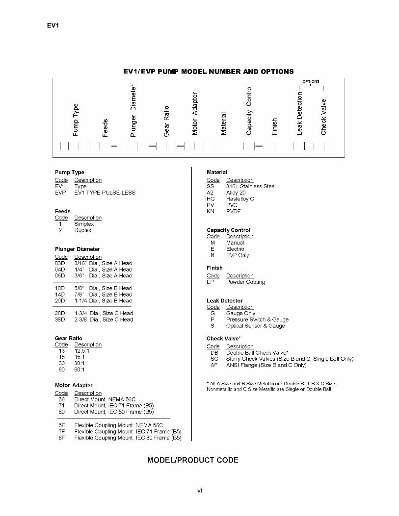
Metering pumps require at least 10-15 PSI differen-tial pressure to operate properly. The dischargepressure must exceed the suction pressure at alltimes to ensure proper check valve operation andto prevent siphoning. If the pump is not dischargingat a sufficient and consistent pressure, then a backpressure valve must be installed. See Figure 2 forthe recommended location.
3.5 START-UP
Once all the checks and procedures describedabove have been carried out, start the pump.
Conduct a visual and audio check of the pump (inparticular, listen for the presence of any “suspi-cious” noises).
Make sure that the stroke adjustment knob isunlocked.
Gradually increase the capacity until liquid can beseen flowing from the priming valve. If no primingvalve is in place, when the liquid end is primed, thedischarge check valves can be heard to be operat-Figure 2. Typical Piping Diagram.

EV1
8
ing (should hear a clicking noise caused by move-ment of check valve balls). When liquid end isprimed, stop the pump and close the priming valve.
Adjust the pump to the desired capacity.
3.6 FLOW RATE ADJUSTMENT
The EV1 flow rate is fully adjustable from 100% ofrated capacity (see name-plate for rated capacity)to 0% flow rate. However, the pump will only beaccurate from 100% to 10% of rated capacity. Flowis varied by turning stroke control knob. Turnedfully counterclockwise is 100% setting or maximumflow. The calibration of stroke length is via the ver-nier scale created by the 10 increments on thestroke adjuster knob and 10 increments on thesleeve.
NOTE
The stroke length scale is a reference ofadjuster setting, NOT flow rate. A calibra-tion curve must be developed to determineflow rate at various settings.
3.7 CALIBRATION
To determine the relationship between the strokeadjuster setting and flow rate, a calibration curvemust be developed. This is easily done by check-ing capacities at various stroke adjuster settingsand plotting points on a graph.
NOTE
The results should approach a straightline, but compressibility, tolerances, andcheck valve losses may yield slight varia-tions. Sample points that are within 3% ofthe maximum flow rate of the unit at 100%stroke setting are deemed acceptable.
3.8 HYDRAULIC PRIMING
The priming of the hydraulics is necessary when-ever the liquid end has been removed. After re-assembly, remove pressure relief valve compo-nents as mentioned in Paragraph 4.6, PlungerBody. Be sure to note the turns needed to removethe adjustment screw, or measure from the top ofthe nut to top of the tower, to remember your reliefvalve setting.
Set the stroke adjuster to approximately 30%. Forfast stroking pumps and those with the largerplunger size of 1-3/4 in and 2-3/8 in stroke adjustershould be set lower.
Start the pump motor while adding the properhydraulic oil into the plunger stem (Relief Valvearea). Run pump for several minutes to allow oil toenter the hydraulic chamber. Stop the pump andre-assemble the pressure relief valve, following theinstructions from Paragraph 4.6, Plunger Body.Return the adjustment screw to its original setting.
Start the pump and operate against zero backpressure. Slowly increase to 1/2 the rated pressureand run for several minutes to allow the hydraulicsto properly prime.
To set the pressure relief valve, follow the direc-tions in paragraph below – Relief Valve Setting.
WARNINGTHE HYDRAULIC RELIEF VALVEPROTECTS THE PUMP ONLY AND ISNOT DESIGNED TO BE USED AS ASYSTEM SAFETY RELIEF VALVE.
3.9 RELIEF VALVE SETTING
To properly set the relief valve certain system com-ponents are necessary.
An accurate liquid dampened gauge, a means ofdeveloping back pressure in excess of designedrelief valve setting, and some means of measuringflow.
If these components are not available in the sys-tem, the pump should be removed and taken backto a test area. Run the pump with little or no backpressure. Slowly increase the back pressure andcheck the pump for delivery of the rated capacity at10% over maximum pressure. If the relief valve isnot set high enough, the flow will taper off, as pres-sure is increased. Slowly increase the relief valveadjustment screw and check the flow rate. If theflow does not increase as relief valve is tightened,another problem such as starved suction or ablocked discharge may exist. Immediately shutdown the pump and find the problem. If the pumpreadily delivers the rated flow at maximum pres-sure, the relief valve may be set too high. Slowly
EV1
9
decrease the relief valve setting until the flowdecreases. Tighten the adjuster until the rated flowis delivered at 10% over the rated pressure.
THE HYDRAULIC RELIEF VALVE PRO-TECTS PUMP GEARING ONLY AND ISNOT DESIGNED TO BE USED AS ASYSTEM SAFETY RELIEF VALVE.
3.10 TROUBLESHOOTING
The EV1 is equipped with an air bleed relief sighttube. This offers a means of viewing the hydraulicoil emitted from both the air bleed valve and reliefvalve. This tube also offers an external means oftroubleshooting.
The sight tube is located under the sight glass onthe top of the drive case located close to plungerbody. If equipped, the pump may have an externalbulls eye.
During normal operation the tube should emit asmall amount of oil on every stroke. This results ina slight percolating action.
If the sight tube is dry, malfunction exists. Any ofthe following may cause this: starved suction, thehydraulics not primed, no oil in the drivecase, theoil filter is clogged or a dirty air bleed valve.
3.11 TOOLS & WORKING FACILITY
There are no special tools needed to perform rou-tine maintenance on the EV1 model pump. Thereare, however, some sub-assemblies that requirespecial fixtures and are sold only as a completeassembly. Contact Milton Roy for identification ofthese components.
For replacement of common wear components, itshould not be necessary to remove the entirepump. The EV1 pump is modular in design andshould require removal of damaged componentonly. Avoid contamination of pump componentsduring maintenance.

EV1
10
THIS PAGE INTENTIONALLY BLANK
EV1
11
SECTION 4 MAINTENANCE
4.1 ROUTINE MAINTENANCE
During normal operation of the pump, replacementof common wear items will become necessary.These are found in the Liquid End Rebuild Kit. Thekit contains recommended items that should bestocked in the customer’s inventory. The frequencyof maintenance on any pump depends on theseverity of service and total hours of operation.Table 1 reflects recommended service intervals.
4.2 SPARE PARTS
The material code, found on the pump’s nameplateand model number are required when ordering anyparts.
Rebuild kits are available for the liquid end, plungerbody, stroke adjuster, and drivecase. The kitsinclude only the wear items recommended for rou-tine maintenance.
The parts section contains cross sectional draw-ings to identify parts by item number. You mustcross reference your particular list to find MiltonRoy's part number.
When pumps of different size or material of con-struction are being serviced, use Milton Roy’s partnumbers taken from the corresponding parts list. A316SS check ball has the same item number as aceramic check ball. Milton Roy's part number, how-ever, will reflect correct construction.
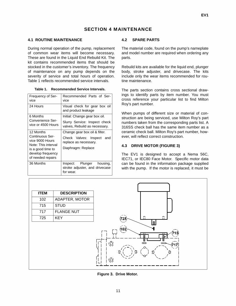
4.3 DRIVE MOTOR (FIGURE 3)
The EV1 is designed to accept a Nema 56C,IEC71, or IEC80 Face Motor. Specific motor datacan be found in the information package suppliedwith the pump. If the motor is replaced, it must be
Table 1. Recommended Service Intervals.
Frequency of Ser-vice
Recommended Parts of Ser-vice
24 Hours Visual check for gear box oiland product leakage
6 MonthsConvenience Ser-vice or 4500 Hours
Initial: Change gear box oil.
Slurry Service: Inspect checkvalves, Rebuild as necessary.
12 MonthsContinuous Ser-vice 9000 HoursNote: This interval is a good time to develop frequency of needed repairs
Change gear box oil & filter.
Check Valves: Inspect andreplace as necessary.
Diaphragm: Replace
36 Months Inspect: Plunger housing,stroke adjuster, and drivecasefor wear.
ITEM DESCRIPTION102 ADAPTER, MOTOR715 STUD717 FLANGE NUT725 KEY
Figure 3. Drive Motor.

EV1
12
identical to the original or a factory approvedequivalent.
NOTE
Motor rotation will not affect pumpperformance or wear, unless fittedfor continuous flow option. (ModelDesignation Pulse-Less).
WARNINGALWAYS DISCONNECT ELEC-TRICAL POWER FROM THEPUMP MOTOR BEFORE PER-FORMING ANY MAINT-ENANCE.FAILURE TO FOLLOW THESEINSTRUCTIONS COULD RESULTIN DEATH OR SERIOUS INJURY.
1. Before removing the drive motor, ensurethat all power is removed and locked out.
2. Remove four (4) 3/8” (9.5mm) attach-ment nuts. Evenly lift motor out. Themotor shaft is coupled to worm shaftwith a 3/16” (7.8mm) square 0.81” key.
3. To reinstall drive motor apply a liberalamount of antiseize to shaft, then place3/16” (7.8 mm) shaft key into worm shaft.Align motor shaft with worm and carefullyinsert. The motor face should meet motoradapter.
4. Evenly draw up four (4) 3/8” (9.5 mm)mounting nuts.
4.4 CHECK VALVES
The check valves are a critical part of ametering pump. Proper maintenance is im-portant to ensure accuracy. Size A, bothmetallic and non-metallic and size B metalliccheck valves are removed and replaced asan assembly. Size B non-metallic and size Cmetallic and non-metallic check valves areremoved and replaced as the following indi-vidual parts: seat, O-ring, guide, cap, seal,and ball (double ball check valve includes atransition piece). Pumps equipped with dou-ble ball check valves (See Figures 6 & 7)maintenance is similar to that of the singleball. Figure 5. Metallic Head Assembly, Size B.
Figure 4. Metallic/Plastic, Head Assembly, Size A.

EV1
13
1. Disconnect piping from union or flangedconnections nearest pump.
2. Prior to removal of check valve caps,pumping cavity must be flushed to removecontaminants.
3. Remove suction and discharge check valvecaps as shown in Figure 4. Be sure not todrop valve components as damage mayoccur.
4. Examine valve seats. The suction valveseat is located in valve cap, dischargevalve seat is located in liquid end. Seat sur-face should be free of burrs or excessivewear. If seats are in need of replacement,liquid end must be removed per Paragraph4.5.
5. On pumps with plunger diameters of 5/8 in.(15.87 mm) to 1-1/4 in. (31.7 mm), dis-charge seat is pressed into liquid end, whilesuction seat is machined into check valvecap. Both caps are identical so a new suc-tion valve seat is available by switchingsuction discharge valve caps. Before re-moval of discharge seat, liquid end must beremoved per Paragraph 4.5. If seat area iscorroded, it may be necessary to tap seatwith 5/16 in (8 mm, 24 UNF thread). Use a5/16 in (8 mm,24 screw and pry out evenly.
6. Pumps equipped with plunger diameters 1-3/4 in. (44.5 mm) and larger, have suctionseat pressed into suction valve cap, anddischarge seat is pressed into liquid end.Use a drift to remove both seats as in step5. If needed, use a 5/8 in (15.9 mm) - 18UNF tap and screw.
7. When new seats are installed, they mustbe coined. Place a check valve ball on ballseat. Using a brass drift on ball strike driftfirmly with hammer. A small chamfer isformed on seat surface.
8. Replace TFE gaskets when valve caps aredisturbed (size B & C only). Removal ofgaskets is accomplished by using a softtool. Do not scratch seal surface.
Figure 6. Plastic Head Assembly, Size B.
Figure 7. Metallic Head Assembly, Size C.
EV1
14
9. When installing a new gasket, be sure sealsurface is clean and gasket is inserted com-pletely into groove.
10. Replace check valve assemblies Figures 4 -7. Torques on valve caps are critical (size B &C only). Consult Table 2 for correct torquevalue. Size A check valve caps are tightenedto compress o-ring.
11. Reinstall piping. It is not recommended thatthreaded connections be wrapped with Teflontape, this is a common cause of check valveclogging. A TFE based sealing compound isrecommended.
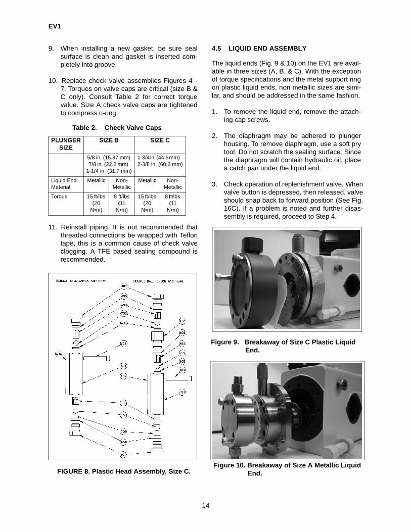
4.5 LIQUID END ASSEMBLY
The liquid ends (Fig. 9 & 10) on the EV1 are avail-able in three sizes (A, B, & C). With the exceptionof torque specifications and the metal support ringon plastic liquid ends, non metallic sizes are simi-lar, and should be addressed in the same fashion.
1. To remove the liquid end, remove the attach-ing cap screws.
2. The diaphragm may be adhered to plungerhousing. To remove diaphragm, use a soft prytool. Do not scratch the sealing surface. Sincethe diaphragm will contain hydraulic oil, placea catch pan under the liquid end.
3. Check operation of replenishment valve. Whenvalve button is depressed, then released, valveshould snap back to forward position (See Fig.16C). If a problem is noted and further disas-sembly is required, proceed to Step 4.
Figure 10. Breakaway of Size A Metallic Liquid End.
Table 2. Check Valve Caps
PLUNGER SIZE
SIZE B SIZE C
5/8 in. (15.87 mm) 7/8 in. (22.2 mm)
1-1/4 in. (31.7 mm)
1-3/4 in. (44.5 mm) 2-3/8 in. (60.3 mm)
Liquid End Material
Metallic Non-Metallic
Metallic Non-Metallic
Torque 15 ft/lbs (20
N•m)
8 ft/lbs (11
N•m)
15 ft/lbs (20
N•m)
8 ft/lbs (11
N•m)
FIGURE 8. Plastic Head Assembly, Size C.
Figure 9. Breakaway of Size C Plastic Liquid End.

EV1
15
4. A new replacement diaphragm is requiredwhenever the liquid end is removed. Refer toTable 5, Page 38 for torque specifications for adiaphragm.
5. Install the liquid end oriented so the flow arrowpoints up on the face, and insert eight (8)attaching screws. Tighten the liquid end boltsin sequence to the maximum torque ratings asindicated, Table 5, Page 38.
6. With the replacement of a diaphragm it is nec-essary to re-prime the hydraulic chamber. Theprocedure for re-priming is found in Section 3,Operation.
7. Replace the check valve assemblies, Para-graph 4.4.
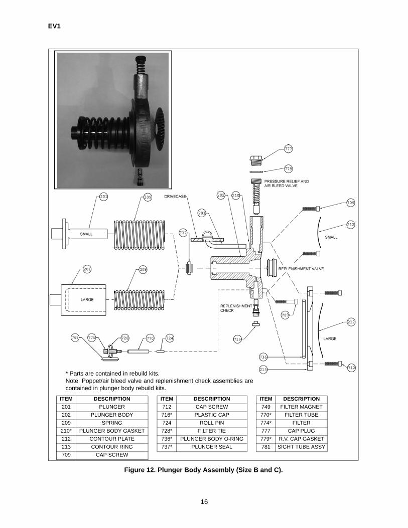
4.6 PLUNGER BODY ASSEMBLY
The function of the plunger body (Figure 12) is tocontrol the hydraulic system. This is the most intri-cate portion of the pump and should be carefullyserviced in a clean environment.
NOTE
Prior to plunger body removal, the gearbox oil must be drained and the liquid endand stroke adjuster removed. The motormust be rotated to place the plunger at thebottom, dead center (full suction stroke).The screws must be removed slowly toallow the plunger return spring to decom-press. Be sure the plunger housing ismoving forward as the attaching screwsare loosened so there is no compressionremaining on the spring.
WARNINGFAILURE TO FOLLOW THESEINSTRUCTIONS MAY RESULT IN ASUDDEN RELEASE OF THE SPRINGCOMPRESSION, LEADING TOSERIOUS INJURY.
1. To remove plunger body, attaching screwsmust be removed.
(1) For small plunger body, remove two (2) 1/4 in (6.4 mm) - 20 cap screws.
(2) For large plunger body, first remove two(2) 1/4 in (6.4 mm) - 20 cap screws thatretain diaphragm support ring, Item 213.Plunger body may now be removed byremoving eight (8) 3/8 in (9.5 mm) - 16cap screws.
2. Remove plunger housing from drivecase, tak-ing care plunger and spring do not fall free.
3. Remove filter assembly from drivecase andinspect. If replacement is necessary, filter maybe removed from magnet by cutting plastic tie.Renew tube if it is damaged or does not fitsnugly onto filter or connector.
4. Clean drivecase carefully. Magnet is designedto attract metal particles. This area will needspecial attention.
5. Carefully slide plunger and spring from plungerbore. Examine plunger for any signs of wear ordamage. Configurations differ by plungersizes. All sizes, however, are functionally sim-ilar.
• Plunger sizes 5/8 in. (15.875 mm), 7/8 in (22.2 mm), 1-1/4 in (31.7 mm) have exter-nal return springs.
• Plunger sizes 1-3/4 in (44.5 mm), 2-1/8 in (54 mm), 2-3/8 in (60.3 mm) have internal-return springs.
Figure 11. Plunger Seal.
EV1
16
ITEM DESCRIPTION ITEM DESCRIPTION ITEM DESCRIPTION201 PLUNGER 712 CAP SCREW 749 FILTER MAGNET202 PLUNGER BODY 716* PLASTIC CAP 770* FILTER TUBE209 SPRING 724 ROLL PIN 774* FILTER210* PLUNGER BODY GASKET 728* FILTER TIE 777 CAP PLUG212 CONTOUR PLATE 736* PLUNGER BODY O-RING 779* R.V. CAP GASKET213 CONTOUR RING 737* PLUNGER SEAL 781 SIGHT TUBE ASSY709 CAP SCREW
* Parts are contained in rebuild kits.Note: Poppet/air bleed valve and replenishment check assemblies arecontained in plunger body rebuild kits.
Figure 12. Plunger Body Assembly (Size B and C).

EV1
17
6. The plunger seal is a 3 piece T-type seal. Thisutilizes an elastomer T-shaped seal with 2plastic support rings (See Figure 11). If nowear is evident and plunger fits snugly intoseal, renewal is not necessary. Seal may NOTbe reused if it is removed from plunger body.
7. To remove plunger seal, both plastic retainingrings must be removed first. Using a smallangled tool, carefully pry out all three sealcomponents.
8. To replace seal, insert first plastic ring intobore. Note orientation of beveled ends. (SeeFigure 11). Plunger seals 1-1/4 in (31.7 mm),1-3/4 in (44.5 mm), 2-3/8 in (60.3 mm), plasticrings contain a machined radius. This radiusmust face center of seal.
9. Install a well lubricated seal into groove inplunger body.
10. Slide retaining ring from bore into far side ofplunger seal.
11. Install second ring into near side of plungerseal, noting position of beveled end andradius, where applicable. Be sure all seal com-ponents are aligned properly.
12. To remove replenishment check, remove pro-tection plug (item 716) and back out of plungerbody using a 1/4 Allen Wrench. Note locationin Figure 12.
13. Examine o-rings for any damage. Check ballshould move freely inside body.
14. If repair of replenishment check is necessary,entire sub-assembly should be replaced (Fig-ure 13).
15. To reinstall replenishment check, generouslylubricate o-rings and insert. Use a gentle turn-ing force until threads catch. Tighten firmly.
16. Insert protection plug, Item 716. Replace whennecessary.
17. The air bleed and pressure relief valve areremoved by backing out large slotted screwfrom stem of plunger housing. (Count numberof turns needed to remove screw and record).Note the orientation of the components asshown in Figure 14.
18. The poppet and air bleed assembly arehoused in the square body. The small airbleed ball should move freely inside the body.If no movement of the air bleed ball is evi-dence, assembly may be flushed with a sol-vent. If a defect is found, assembly is to bereplaced with a factory assembled unit.
19. The relief spring in each liquid end is specificfor each application (Under no circumstancesshould any other spring be used in this assem-bly).
20. To re-assemble pressure relief valve, insertpoppet/air bleed assembly into stem. Be sure itis centered and properly located onto seat.Insert spring and screw, making sure to returnthe screw to its original location. As noted ear-lier the final setting of the pressure relief valveis covered in Section 3, Operation. Be sure toinstall protection cap, Item 777 prior to installa-tion.
ITEM DESCRIPTION206 REPL CHECK BODY211 REPL CHECK ROLL PIN729 REPL CHECK O-RING730 REPL CHECK O-RING751 BALL
SIZE B & C
FIGURE 13. Replenishment Check Assembly.

EV1
18
21. To access replenishment valve, remove rearsupport plate, Item 212 (size B & C only). Toremove valve, tap lightly with a soft rod throughplunger bore on back side of valve (See Fig-ure 12).
22. The face of the valve should be secure to thespool via a press fit. The spool should movefreely in the valve and easily return to forwardposition via a conical spring (See Figure 15).
23. When action of valve is not smooth, replace-ment of entire assembly is necessary.
24. O-rings should not be reused. Remove old o-rings carefully. Ensure there are no sharpedges on exterior of valve body.
25. Lubricate new o-rings with hydraulic oil andcarefully install. Place plunger housing face upon firm table. Generously lubricate valve boreand set valve squarely into opening. Rotatevalve until one hole in valve body (Figure 16A)is aligned with hole in plunger body (Figure16B) and press valve into plunger housing.
ITEM DESCRIPTION501 REPL VALVE NUT502 REPL VALVE POPPET503 AIR BLEED VALVE SCREW504 REPL VALVE SPRING750 AIR BLEED BALL755 POPPET BALL778 ALIGNMENT COLLAR
ITEM DESCRIPTION203 REPL VALVE SPOOL205 REPL VALVE HEAD207 REPL VALVE HOUSING208 REPL VALVE SPRING732* REPL VALVE O-RING733* REPL VALVE 0-RING734* REPL VALVE 0-RING
* Parts are containedin rebuild kits.
NOTE:
Poppet/air bleed valve and replacement check assemblies are contained in plunger body rebuild kits.
Figure 15. Replenishment Valve Assembly (Size B & C).
FIGURE 14. Pressure Relief/Air Bleed Assem-bly (Size B & C).
Figure 16A.
Replenishment Valve Hole.
Figure 16B. Plunger Body Hole.

EV1
19
26. To ensure that replenishment valve is installedcompletely, place rear contour plate Item 212(Figure 12) onto plunger body. The plateshould fit tightly to the body without any rock-ing action (Figure 16C).
27. The plunger and return spring may now beinstalled. Lubricate bore and plunger gener-ously. Using an even rotational force on backof plunger, press plunger into bore. On 1-3/4in. (44.5 mm) plunger, be sure to install springsupport ring as shown in Figure 12.
28. Insert filter magnet assembly into drivecase.Ensure tube is securely fastened to pin, Item724 (Figure 12) and filter. The tube must notcome in contact with the eccentric or theplunger return spring.
29. Before installing the plunger body, be sure thestroke adjuster is set at 100% and the motor isrotated until the eccentric is at its lowest pointin relation to plunger contact (full suctionstroke).
30. Position gasket so all required holes arealigned. Be sure replenishment and hydraulicrelief valve holes are in proper orientation. Thelarger hole is for the hydraulic relief valve port.
31. Insert plunger body so that stem is pointing up.The two different positions available are found
when pump motor is mounted in either horizon-tal or vertical positions.
32. Evenly draw up body with attaching bolts. SeeTable 3 for proper torque settings.
33. Re-assemble liquid end as described in Para-graph 4.5.
34. Before restarting pump, make sure drivecaseis properly refilled with oil. The relief valve set-ting also must be verified. See Section 3,Operation.
4.7 STROKE LENGTH ADJUSTMENT ASSEM-BLY
The stroke length adjustment assembly is a gradu-ated plunger stop which allows the pump to have avariable stroke length at a fixed frequency. Due tothe complexity of this component, we recommenda new assembly be purchased if major rework isnecessary.
1. Prior to disassembly set the stroke adjuster at100%. This will allow the plunger spring torelax and ease the housing removal. Onpumps with vertical motors, the gear box oilmust be drained.
2. Detach the housing by removing the two (2)cap screws and retract the assembly (See Fig-ure 17). See the breakdown of the assembly inFigure 18.
3. Remove the adjuster knob with a 9/64 in (3.6mm) Allen Wrench on the set screw located atthe collar.
Table 3. Plunger Housing Bolt Size
BOLT SIZE 1/4 IN. (6.4 MM) 3/8 IN. (9.5 MM)
5/8 in. (15.87 mm)7/8 in. (22.2 mm)1-1/4 in. (31.7 mm)
100 in/lb (11 N•m)
1-3/4 in. (44.5 mm) 2-3/8 in. (60.3 mm)
40 ft/lb (54 N•m)Figure 17. Stroke Adjuster Housing.
Figure 16C. Plunger With Replenishment Valve and Rear Contour Plate Installed.

EV1
20
4. Remove the calibrated sleeve, Item 303.
5. Both the knob and sleeve utilize locating o-rings. It is not necessary to replace the o-ringsunless they are damaged.
6. The knob o-ring, Item 732, is located inside, atthe end of the bore. Remove with small angledtool. If replacement is necessary, lubricate withlight oil.
7. The sleeve o-ring, Item 735, is located on theoutside of the adjuster housing. If replacementis necessary, do not lubricate.
8. Adjust the plunger stop until there is 1-3/16 in.(30 mm) from end of screw to bottom of smallgear (Figure 19).
NOTE
Be sure that stop screw and small gear arefirmly pressed against ear of housing (SeeFigure 19).
FIGURE 19. Stroke Adjuster Assembly.
ITEM DESCRIPTION*108 STROKE ADJUSTER COVER GASKET*301 STROKE SDJUSTER HOUSING*302 PLUNGER STOP*303 STROKE ADJUSTER SLEEVE*304 STROKE ADJUSTER GEARSHAFT*305 STROKE ADJUSTER SHAFT SCREW*306 STROKE ADJUSTER KNOB*307 BEVELED GEAR WASHER*308 BEVELED PIN*309 BEVELED GEAR*326 PLUNGER STOP BUSHING702 SOCKET HEAD CAP SCREW*714 SET SCREW*718 SPRING WASHER*723 ROLL PIN*731 O-RING*732 O-RING*735 O-RING*784 SET SCREW
* Parts are contained in rebuild kits.Note: Poppet/air bleed valve and replace-ment check assemblies are contained in plunger body rebuild kits.
Figure 18. Manual Stroke Adjuster.

EV1
21
9. Insert the collar, Item 326, into housing ear.Install two (2) set screws Item 784. Doublecheck distance in Step 8 and firmly secure thetwo (2) set screws.
10. Install O-ring on outside of housing stem andpress on calibrated sleeve. Use no lubricant.Calibration marks should face top of pump.
11. Install the o-ring, Item 732, into strokeadjuster knob.
12. Place the adjusting knob on the shaft and dialin, clockwise, until the adjustment bottoms.Back out a 1/2 turn and affix with the setscrew. Be sure that the “zero” mark on knobaligns with “zero” on the calibrated sleeve.
13. Check for proper operation.
14. Install assembly using a new gasket and two(2) cap screws.
15. It is necessary to verify plunger stop adjust-ment whenever the stroke adjuster has beenremoved. To check, dial stroke adjuster to 0%.There must be NO plunger movement presentwhile the pump is operating.
16. If plunger movement is present, repeat theadjustment procedure from Step 8. Increasethe measurement from 1-3/16 in (30 mm)gradually until Step 15 is met.
4.8 ELECTRONIC ACTUATOR ALIGNMENT PROCEDURE
The operation of the stroke adjuster can be auto-mated with the installation of an electronic actua-tor.
Actuator:
Jordan Control Multiturn Actuator Model SM1010
WARNINGACTUATOR MUST NOT BE POWEREDUNLESS PUMP MOTOR ISOPERATING.
BE SURE PROPER SAFETY PRECAU-TIONS ARE TAKEN WHEN ADJUSTINGTHE JORDAN ACTUATOR.
Figure 20. Wiring Diagram.
Figure 21. Upper PC Board.
EV1
22
NOTE
The pump motor must be operating to per-form any actuator adjustments.
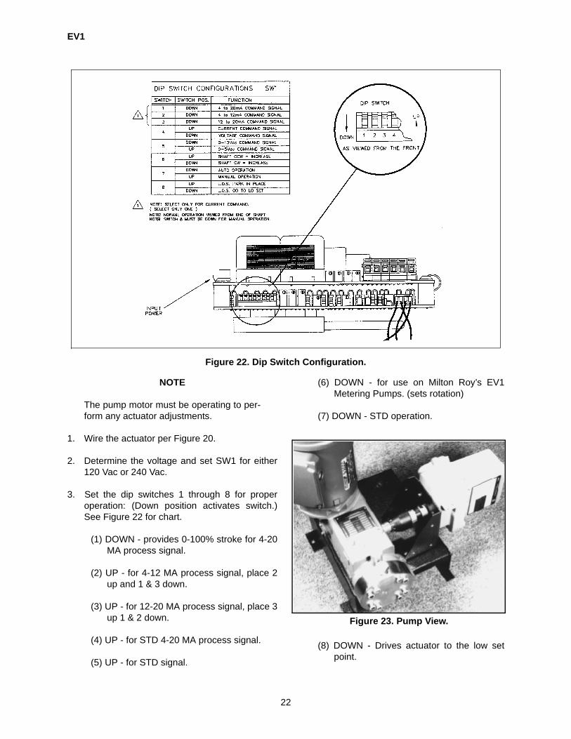
1. Wire the actuator per Figure 20.
2. Determine the voltage and set SW1 for either120 Vac or 240 Vac.
3. Set the dip switches 1 through 8 for properoperation: (Down position activates switch.)See Figure 22 for chart.
(1) DOWN - provides 0-100% stroke for 4-20MA process signal.
(2) UP - for 4-12 MA process signal, place 2up and 1 & 3 down.
(3) UP - for 12-20 MA process signal, place 3up 1 & 2 down.
(4) UP - for STD 4-20 MA process signal.
(5) UP - for STD signal.
(6) DOWN - for use on Milton Roy’s EV1Metering Pumps. (sets rotation)
(7) DOWN - STD operation.
(8) DOWN - Drives actuator to the low setpoint.
Figure 22. Dip Switch Configuration.
Figure 23. Pump View.

EV1
23
4. Leave pump side of coupling loose and actua-tor side tight.
5. Apply a 4 MA signal until LS1 LED (Red) is lit -adjust low set point to achieve this.
6. Adjust low set point until LED 1 (Yellow LED onlower board) just shuts off.
7. Tighten pump side coupling set screw.
8. Apply a 12 MA signal and adjust high set point(pot is located on lower board) so pump settingis 50%.
9. Apply a 20 MA signal and adjust LS2 so pumpsetting does not exceed 99%. LED 2 (Green)should be lit. (CCW reduces setting).
10. Adjust the high set point so LS2 LED (Red)just shuts off.
11. Set current limit pot located on lower board tofull setting by turning full clockwise. This isnoted by a slight click.
12. Set motor speed by adjusting motor speed poton lower board. Set for approximately 10 RPM(Figure 25).
4.9 MOTOR ADAPTER/ECCENTRIC SHAFT ASSEMBLY
The motor adapter serves two functions in thepump. It provides a C-Face mounting for the drivemotor and locates the worm shaft drive gear. Theadapter is fabricated in cast iron for durability. Theeccentric shaft assembly when coupled with wormshaft, provides the proper strokes per minute. Therotational motion of the worm shaft is converted toreciprocating motion through the use of a cam onthe eccentric shaft.
With the motor removed, Paragraph 4.3, it is possi-ble to remove the motor adapter. This assemblyhouses the worm shaft.
1. Remove four (4) mounting screws and lift outassembly.
2. Remove seal, item 740 and spirolox retainingring, item 745. Invert motor adapter and pressout worm shaft.
3. Remove snap ring, item 747. Support innerbearing race and press out worm shaft.
4. Press out needle bearing from inside of drivecase. Allow bearing to push out plug, item766. Multiplex units will have an oil seal, item775, instead of a plug.
5. The new needle bearing needs to be pressedinto place from inside the drive case. Use apress tool with an O. D. slightly smaller thanthe O. D. of the bearing to support the side wallof the bearing. Press in bearing until it is 3/32in. below machined surface.
Figure 24. Lower PC Board.
Figure 25. Speed/Torque Curve.

EV1
24
6. Reinstall worm shaft plug, item 776, or new oilseal, item 775.
7. Press new bearing on to worm shaft until it bot-toms on shoulder of shaft. Secure with a newsnap ring, item 747.
8. Press shaft and bearing assembly into motoradapter. Secure with a new spirolox retainer,item 745.
9. Install new oil seal, with lip side towards gearbox. Press into adapter until top of seal isbelow chamfer in adapter.
NOTE
To replace the oil seal, strike a small sharptool to perforate the oil seal near the perim-eter. Pry out the seal with a proper tool.
10. The eccentric shaft will generally require noservice for the life of the pump. When a gear
ratio change is required, consult the factory forspecial instructions. See Figure 26 for partsidentification.
11. Place gasket, item 111 on drive case andinstall motor adapter/worm gear assembly.
12. Secure with four (4) screws. Draw up evenlyand torque to approximately 50 in/lbs (6 N•m).
13. Reinstall motor - Paragraph 4.3.
4.10 DRIVE CASE ASSEMBLY
The drivecase (Figure 27) is cast iron, and is builtfor durability and precision. It may be easily disas-sembled with the exception of the eccentric shaft,hub, and gear, which are inserted into the gear boxusing special tooling. When gearing needs to bechanged, consult the factory for special instruc-tions.
ITEM DESCRIPTION102 MOTOR ADAPTER103 ECCENTRIC SHAFT104 ECCENTRIC GEARHUB*111 C-FACE MOTOR ADAPTER PINION
GASKET112 GEAR SUBASSEMBLY112A WORMSHAFT (SOLD WITH ITEM 112)113 GEAR SUBASSEMBLY (MULTIPLEX)113A WORMSHAFT (SOLD WITH ITEM 113)708 SCREW715 STUD717 FLANGE NUT720 DOWEL PIN*740 INPUT SHAFT SEAL745 SNAP RING WORM BEARING746 ECCENTRIC SHAFT SNAP RING747 SNAP RING WORM SHAFT748 ECCENTRIC BEARING SNAP RING756 ECCENTRIC SHAFT BALL763 NEEDLE BEARING STD.764 NEEDLE BEARING OPEN766 NEEDLE BRG.768 BALL BEARING769 BALL BRG.775 OIL SEAL776 DRIVE CASE PLUG* Parts are contained in rebuild kits.Note: Poppet/air bleed valve and replacement check assemblies are contained in plunger body rebuild kits.
Figure 26. Motor Adapter/Eccentric Shaft Assembly.

EV1
25
Two (2) baseplate configurations, horizontal or ver-tical, are supplied for the EV1. The design isdependent upon motor orientation.
The second feed plunger housing and strokeadjuster’s cover utilize a gasket. If a leak isdetected or an assembly removed, a new gasket isneeded. Directions for installing new componentsare found in their designated section.
Eccentric shaft retainers, item 106, are used tocenter the shaft by providing a bearing surface for3/8 in. (9.5 mm) balls. Gaskets used under theseshaft retainers are of various thicknesses and arepicked to provide the proper end play. Different col-ors have been selected for each available thick-ness. When ordering new gaskets be sure tospecify the needed colors, as originally suppliedwith the pump.
All EV1 drive cases must have a breather.
The drivecase is powder coated with a polyesterTGIC to aid in chemical resistance. If power coat
becomes chipped or corroded, it should be powdercoated to prevent damage to drivecase.
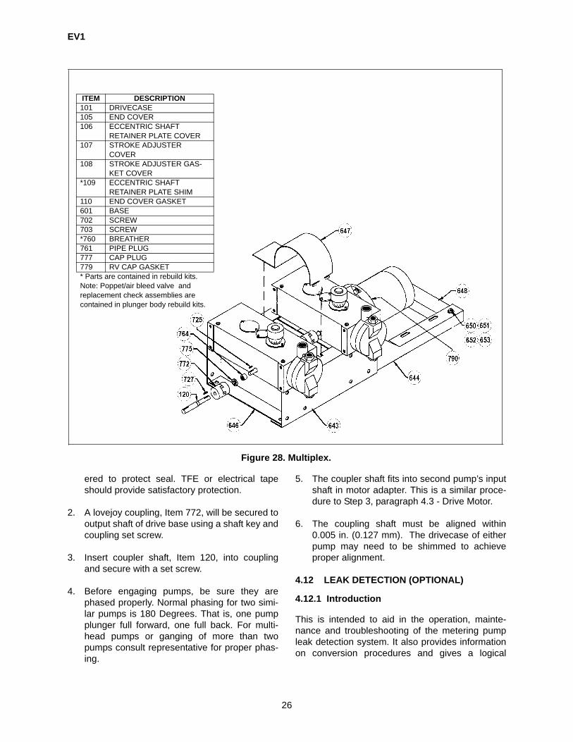
4.11 MULTIPLEX
Multiplex pumps utilize a single motor to power twoor more pumps. Since most of the required HP of amotor is not needed throughout the entire stroke, asecond pump will require only slightly more HP.Multiplexing, along with the dual feed design, offersunlimited options and unparalleled flexibility.
Multiplexing is accomplished by mounting a pumphorizontally and retrofitting a new extended wormshaft. Note breakdown in Figure 28. Instructionsare found in Paragraph 4.9 for installation of stan-dard worm shaft.
Follow Step 6 in Paragraph 4.9, motor adapter, topress in new needle bearing, item 764.
1. Oil seal, Item 775, must be pressed until flushwith face of gear case. Ensure keyway is cov-
ITEM DESCRIPTION101 DRIVECASE105 END COVER106 ECCENTRIC SHAFT
RETAINER PLATE COVER107 STROKE ADJUSTER
COVER108 STROKE ADJUSTER GAS-
KET COVER*109 ECCENTRIC SHAFT
RETAINER PLATE SHIM110 END COVER GASKET641 BASE702 SCREW703 SCREW753 SIGHT PLUG*760 BREATHER761 PIPE PLUG777 CAP PLUG779 RV CAP GASKET* Parts are contained in rebuild kits.Note: Poppet/air bleed valve and replacement check assemblies are contained in plunger body rebuild kits.
Figure 27. Drivecase.
EV1
26
ered to protect seal. TFE or electrical tapeshould provide satisfactory protection.
2. A lovejoy coupling, Item 772, will be secured tooutput shaft of drive base using a shaft key andcoupling set screw.
3. Insert coupler shaft, Item 120, into couplingand secure with a set screw.
4. Before engaging pumps, be sure they arephased properly. Normal phasing for two simi-lar pumps is 180 Degrees. That is, one pumpplunger full forward, one full back. For multi-head pumps or ganging of more than twopumps consult representative for proper phas-ing.
5. The coupler shaft fits into second pump’s inputshaft in motor adapter. This is a similar proce-dure to Step 3, paragraph 4.3 - Drive Motor.
6. The coupling shaft must be aligned within0.005 in. (0.127 mm). The drivecase of eitherpump may need to be shimmed to achieveproper alignment.
4.12 LEAK DETECTION (OPTIONAL)
4.12.1 Introduction
This is intended to aid in the operation, mainte-nance and troubleshooting of the metering pumpleak detection system. It also provides informationon conversion procedures and gives a logical
ITEM DESCRIPTION101 DRIVECASE105 END COVER106 ECCENTRIC SHAFT
RETAINER PLATE COVER107 STROKE ADJUSTER
COVER108 STROKE ADJUSTER GAS-
KET COVER*109 ECCENTRIC SHAFT
RETAINER PLATE SHIM110 END COVER GASKET601 BASE702 SCREW703 SCREW*760 BREATHER761 PIPE PLUG777 CAP PLUG779 RV CAP GASKET* Parts are contained in rebuild kits.Note: Poppet/air bleed valve and replacement check assemblies are contained in plunger body rebuild kits.
Figure 28. Multiplex.

EV1
27
course of action and diagnosis should service berequired.
SYSTEM DESCRIPTIONS
A. Gauge Type
This option offers a visual response using a pres-sure gauge to indicate a diaphragm failure. If a dia-phragm fails the vacuum between the doublediaphragm is lost and an increase in pressure willoccur.
B. Pressure Switch
This option offers an electrical interface by provid-ing an N/O or N/C relay. The switch is plumbed tothe center of the diaphragm assembly and sensesthe presence of fluid. In the event of a diaphragmfailure the relay will activate.
C. Fiber Optic
This option offers a visual and electrical interfacethrough an N/O or N/C relay. The optic probe isplumbed to the center of the diaphragm assemblyand senses the presence of fluid. In the event of adiaphragm failure the relay will activate.
All units come from the factory fully assembled,tested and mounted to the pump.
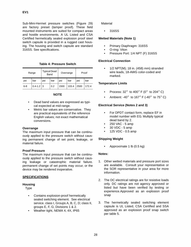
4.12.2 Specifications
A. Gauge TypeType: Dual Purpose (Vacuum/Pressure)Range: 30 In Hg - 300 PSIG
B. Pressure SwitchFurnished with specific orders: available in NEMA4 or NEMA 7
Power Supply CableMaterial: PVCLength: Six (6)Gauge: Five (5) Wire 20 Gauge
Fiber Optic CableType: Flexible Optic CableMaterial: Stainless Steel
4.12.3 Pressure Switch
C. Optic Probe (NEMA 4)SENSOR POWER BLOCK MODULESupply Voltage Construction24-250/1/50-60 Vac 24-36 Vdc
Valox thermoplastic polyes-ter housing; Lexan trans-parent cover
Supply Current Maximum 45 mA
Available EnclosuresNEMA 4: Explosion Proof
Internal SensingIndicationRed LED Activation
Weight
Approximately 1.0 lb.
External SensingIndication
Operation Temperature
Relay Interface 0 to +50 C
+32 to +122 F
RELAY INTERFACEOutput Configu-ration
Output Rating
Internal form“C” Relay (SPDT)
Max.switching power = 150W, 600 VAMax. switching voltage = 250 Vac or 30 VdcMax. switching current = 5AMin. voltage/current = 5 Vdc,0.1 A
C. Optic Probe (NEMA 4)
° °° °
Order Number6AT-EF19-M4-CIA-TTComes with SS oversizedtag, permanently attached.
Figure 29. Pressure Switch.
EV1
28
Sub-Mini-Hermet pressure switches (Figure 29)are factory preset (tamper proof). These fieldmounted instruments are suited for compact areasand hostile environments. A UL Listed and CSACertified hermetically sealed explosion proof steelswitch capsule is provided in a rugged cast hous-ing. The housing and switch capsule are standard316SS. See specifications.
NOTE
• Dead band values are expressed as typi-cal expected at mid-range.
• Metric bar values are conservative. They are practical equivalents of the reference English values; not exact mathematical conversions.
OverrangeThe maximum input pressure that can be continu-ously applied to the pressure switch without caus-ing permanent change of set point, leakage, ormaterial failure.
Proof PressureThe maximum input pressure that can be continu-ously applied to the pressure switch without caus-ing leakage or catastrophic material failure.permanent change of set points may occur, or thedevice may be rendered inoperative.
SPECIFICATIONS
Housing Type
• Contains explosion-proof hermetically sealed switching element. See electrical service. class I, Groups A, B, C, D; class II, groups E, F, G; Divisions 1 & 2.
• Weather tight, NEMA 4, 4X, IP65
Material
• 316SS
Wetted Materials (Note 1)
• Primary Diaphragm: 316SS• O-ring: Viton• Pressure Port: 1/4 NPT (F) 316SS
Electrical Connection
• 1/2 NPT(M); 18 in. (458) mm) stranded wire leads, 18-AWG color-coded and marked.
Temperature Limits
• Process: 32 to 400 F (0 to 204 C)
• Ambient: -40 to 167 F (-40 to 75 C)
Electrical Service (Notes 2 and 3)
• For DPDT contact form, replace EF in model number with EG. Multiply typical dead band by 2.
• 250 VAC - 5 amp• 30 VDC - 5 amp• 125 VDC - 0.5 amp
Shipping Weight
• Approximate 1 lb (0.5 kg)
Notes:
1. Other wetted materials and pressure port sizesare available. Consult your representative orthe SOR representative in your area for moreinformation.
2. The DC electrical ratings are for resistive loadsonly. DC ratings are not agency approved orlisted but have been verified by testing orexperience.Approved as an explosion proofsnap
3. The hermetically sealed switching elementcapsule is UL Listed, CSA Certified and SSAapproved as an explosion proof snap switchper table 5.
Table 4: Pressure Switch
Range Typical Dead Band Overrange Proof
psi bar psi bar psi bar psi bar
6-8 0.4-1.2 3 0.2 1500 103.4 2500 172.4
° ° ° °° ° ° °

EV1
29
DIMENSIONS
Linear = MMIN
Dimensions (Figure 30) are for reference only.Contact the factory for certified drawings for a par-ticular model number.
ELECTRICAL CONNECTION
Use a 1-1/8 in (29 mm) open-end wrench to holdthe hex on the electrical connection while conduitor conduit fitting is being tightened.
The electrical switch element capsule assemblycontains UL Listed and CSA Certified factory-
sealed leads. A conduit seal is not required to pre-serve explosion proof integrity. Electrical leads aremarked NC (normally Closed), NO (NormallyOpen) and C (Common). Electrical switching ele-ments are snap-action and are either SPDT orDPDT (2-SPDT) set to actuate simultaneously. SeeDiagram below.
DO NOT USE A PIPE WRENCH ORSTRAP WRENCH ON THE ROUNDBODY OR AN OPEN-END WRENCH ONTHE HEX PRESSURE PORT WHILETIGHTENING THE CONDUIT CONNEC-TION, BECAUSE THE HERMETICALLYSEALED SWITCHING ELEMENT CAP-SULE HAS BEEN PRECISELY POSI-TIONED AND LOCKED DURINGMANUFACTURE. EXCESSIVE FORCECOULD OVERCOME THE LOCK ANDCAUSE MOVEMENT WHICH WILLADVERSELY AFFECT OPERATION ORRENDER THE PRESSURE SWITCHINOPERATIVE. SHOULD MOVEMENTOCCUR, FACTORY CALIBRATIONMUST BE PERFORMED IN ORDER TORESTORE NORMAL OPERATION.
Table 5. Agency Approvals
Agency Hazardous Location Condi-tions
UL Listed Class I, Group A, B, C, & DClass II, Group E, F, & GDivision 1 & 2
CSA Certified
SAA Approved Ex s IIC T6 for Class I, Zone 1DIP Type B 80 C for Class II, Div. 1 & 2
°
Figure 30. Pressure Switch Dimensions.

EV1
30
4.12.4 Wiring
NEMA 4 Optic Probe Wiring Diagrams
Supplemental wiring diagrams issued for NEMA 7applications
The use of black and yellow results in a normallyopened contact and when tripped will close the cir-cuit.
The use of white and yellow results in a normallyclosed contact and when tripped will open the cir-cuit.
DC hookup is without regard to power supply polar-ity.
4.12.5 Operation
The Evolution Series metering pump leak detectionpackage is designed to sense and indicate a dia-phragm rupture. The standard package offers threemeans of indication.
The diaphragm assembly is a double diaphragmconfiguration in which the diaphragms are phasedtogether by evacuating all of the air between them.
'
A. Gauge Type
The first form of rupture indication is a visual read-ing of the supplied vacuum/pressure gauge. Duringnormal operation the gauge indicates a vacuum of20 inch HG to 0 psi. In the event of a diaphragmfailure this gauge will indicate a positive pressureapproximately equal to line pressure.
B. Pressure Switch
The second form of rupture indications 'is achievedthrough the use of a pressure switch. In the eventof a diaphragm failure, process pressure will act onthe pressure switch. The switch will then activateoffering electrical interface per the specific switchspecifications. The application of the pressureswitch option must be reviewed to Insure properoperation. The performance of the switch isimproved as the process pressure increases. It isrecommended a back-pressure valve be installed ifthe process pressure is less than 50 PSI. See theREACTION TIME vs. PRESSURE graph above.
C. Optic Probe
This third form of rupture Indication is achievedthrough the use of an optic probe. The probe isinserted into a TEE which is mounted directly to theliquid end. In the event of a diaphragm failure fluidwill be forced Into the TEE. The Optic probe willthen be activated. Two forms of notification arestandard with the optics package. The red LED onthe sensor body and the relay interface will bothactivate upon diaphragm failure. The optics pack-age is the quickest form of diaphragm rupturedetection available. This option is especially usefulfor low pressure applications. See the REACTIONTIME vs. PRESSURE graph above.
Wire Color ConnectionBrown (L1) Power inputBlack (N/O) Normally open relay connectionYellow (C) Relay common
White (N/C) Normally closed relay connectionBlue (L2) Power input
Figure 31. Optic Probe.
Figure 32. Reaction Time vs. Pressure.
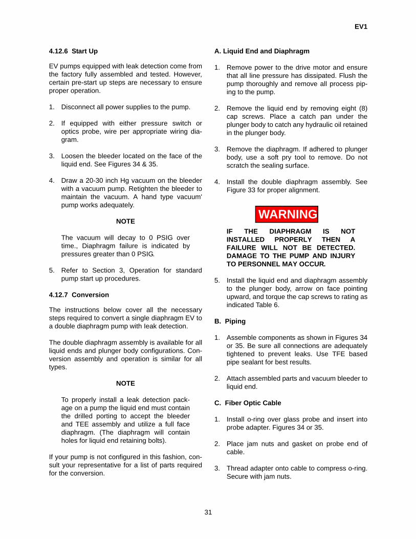
EV1
31
4.12.6 Start Up
EV pumps equipped with leak detection come fromthe factory fully assembled and tested. However,certain pre-start up steps are necessary to ensureproper operation.
1. Disconnect all power supplies to the pump.
2. If equipped with either pressure switch oroptics probe, wire per appropriate wiring dia-gram.
3. Loosen the bleeder located on the face of theliquid end. See Figures 34 & 35.
4. Draw a 20-30 inch Hg vacuum on the bleederwith a vacuum pump. Retighten the bleeder tomaintain the vacuum. A hand type vacuum'pump works adequately.
NOTE
The vacuum will decay to 0 PSIG overtime., Diaphragm failure is indicated bypressures greater than 0 PSIG.
5. Refer to Section 3, Operation for standardpump start up procedures.
4.12.7 Conversion
The instructions below cover all the necessarysteps required to convert a single diaphragm EV toa double diaphragm pump with Ieak detection.
The double diaphragm assembly is available for allliquid ends and plunger body configurations. Con-version assembly and operation is similar for alltypes.
NOTE
To properly install a leak detection pack-age on a pump the liquid end must containthe drilled porting to accept the bleederand TEE assembly and utilize a full facediaphragm. (The diaphragm will containholes for liquid end retaining bolts).
If your pump is not configured in this fashion, con-sult your representative for a list of parts requiredfor the conversion.
A. Liquid End and Diaphragm
1. Remove power to the drive motor and ensurethat all line pressure has dissipated. Flush thepump thoroughly and remove all process pip-ing to the pump.
2. Remove the liquid end by removing eight (8)cap screws. Place a catch pan under theplunger body to catch any hydraulic oil retainedin the plunger body.
3. Remove the diaphragm. If adhered to plungerbody, use a soft pry tool to remove. Do notscratch the sealing surface.
4. Install the double diaphragm assembly. SeeFigure 33 for proper alignment.
WARNINGIF THE DIAPHRAGM IS NOTINSTALLED PROPERLY THEN AFAILURE WILL NOT BE DETECTED.DAMAGE TO THE PUMP AND INJURYTO PERSONNEL MAY OCCUR.
5. Install the liquid end and diaphragm assemblyto the plunger body, arrow on face pointingupward, and torque the cap screws to rating asindicated Table 6.
B. Piping
1. Assemble components as shown in Figures 34or 35. Be sure all connections are adequatelytightened to prevent leaks. Use TFE basedpipe sealant for best results.
2. Attach assembled parts and vacuum bleeder toliquid end.
C. Fiber Optic Cable
1. Install o-ring over glass probe and insert intoprobe adapter. Figures 34 or 35.
2. Place jam nuts and gasket on probe end ofcable.
3. Thread adapter onto cable to compress o-ring.Secure with jam nuts.
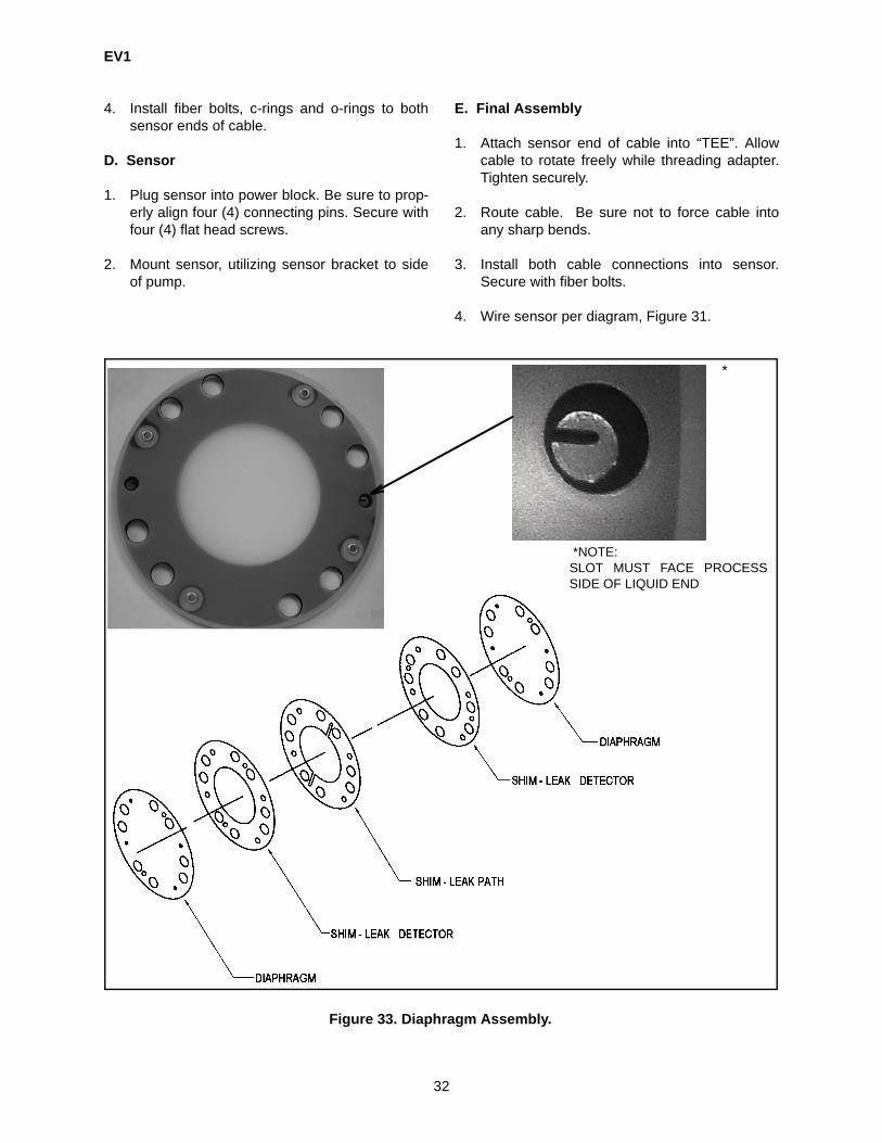
EV1
32
4. Install fiber bolts, c-rings and o-rings to bothsensor ends of cable.
D. Sensor
1. Plug sensor into power block. Be sure to prop-erly align four (4) connecting pins. Secure withfour (4) flat head screws.
2. Mount sensor, utilizing sensor bracket to sideof pump.
E. Final Assembly
1. Attach sensor end of cable into “TEE”. Allowcable to rotate freely while threading adapter.Tighten securely.
2. Route cable. Be sure not to force cable intoany sharp bends.
3. Install both cable connections into sensor.Secure with fiber bolts.
4. Wire sensor per diagram, Figure 31.
*
*NOTE:SLOT MUST FACE PROCESSSIDE OF LIQUID END
Figure 33. Diaphragm Assembly.

EV1
33
4.12.8 Calibration
The only calibration necessary for the Leak Detec-tion System is the adjustment of the sensitivity poton the optics type leak detection options.
1. Remove sensor ends of cable. Carefully' un-thread probe end from TEE.
2. Remove sensor cover by un-threading flathead screw to access sensitivity pot.
3. Energize unit with proper supply voltage.
4. While probe is exposed to air, red LED indica-tor should be lit. Adjust pot clockwise to reducesensitivity until LED is illuminated.
5. To properly adjust sensitivity and test opera-tion, immerse probe into small amount of liq-uid. When probe contacts liquid, sensor shouldlight and relay activate. if liquid is not sensedby probe, adjust pot counterclockwise toincrease sensitivity.
ITEM DESCRIPTION515 PLUG
ITEM DESCRIPTION502 NIPPLE514 PRESSURE
SWITCH
ITEM DESCRIPTION901 LIQUID END111 DIAPHRAGM506 NIPPLE505 TEE BLOCK507 VACUUM BREAKER504 GUAGE
ITEM DESCRIPTION509 ADAPTER PROBE511 CABLE510 GLASS ROD512 SENSOR513 POWER BLOCK
Figure 34. Metallic Leak Detection.

EV1
34
ITEM DESCRIPTION901 LIQUID END111 DIAPHRAGM505 TEE BLOCK507 VACUUM BREAKER504 GUAGE AND SEAL517 FACE PLATE520 BLEEDER ADAPTER519 ADAPTER SEAL518 TEE ADAPTER
ITEM DESCRIPTION509 ADAPTER
PROBE511 CABLE510 CLASS ROD512 SENSOR513 POWER
BLOCK
ITEM DESCRIPTION515 PLUG
ITEM DESCRIPTION502 NIPPLE514 PRESSURE
SWITCH
Figure 35. Non-Metallic Leak Detection.

EV1
35
6. Repeat test operation until liquid is sensed assoon as probe contacts liquid.
NOTE
Be sure to thoroughly dry probe betweentests.
To increase sensitivity - adjust pot counterclock-wise.
To decrease sensitivity - adjust pot clockwise.
4.13 EVP PULSE-LESS OPTION
4.13.1 Introduction
The EV1 metering pump fitted with the Pulse-Lesscam option provides constant flow on suction, ordischarge. This allows the EVP to handle manyapplications where other types of pumps are notwell-suited.
The Pulse-Less option is available on the EVPpump with minor modifications. A duplex pumpwith a specially machined cam, replaces theeccentric/bearing assembly and the stroke adjusterassemblies are removed. The special plungers are
equipped with hardened cam rollers for anextended service life. See Figure 37.
4.13.2 Installation
For the pump to operate In a "constant” flow man-ner, both feeds of the pump must be manifolded.The most effective operation is accomplished bysymmetrical piping connections.
The motor rotation determines the behavior of thepump. To operate in a constant suction mode themotor must be wired to rotate counter-clockwisewhen facing the input shaft. Clockwise rotation willprovide constant discharge.
4.13.3 Operation
The flow is varied by adjusting the speed of themotor (AC or DC) by means of a variable speeddrive controller. For proper operation of the pump,the stroke speed of the pumps should not go lowerthan 15 strokes per minute (19 SPM on 3/8 in.plunger).
NOTE
This limits the turndown to a maximum of10:1 for the fastest stroking pump. If the100% stroke speed is less than 138, thenthe turndown will be less. The flow curvehowever, is linear at all times.
Since the constant flow relies on each of theduplex liquid ends to provide the same flow charac-teristics, it is imperative that each feed is set upand operates identically. For example, if one reliefvalve Is relieving the totalized flow will not be con-stant. See the troubleshooting guide Section 5 ofthis manual for details on any problems encoun-tered.
4.13.4 Maintenance
For standard maintenance issues concerning theliquid end assembly, the plunger assembly (lessthe plunger Item 201), see Figure 37.
4.13.5 Plunger Assembly
1. The plunger assembly differs slightly from thestandard (Figure 37). Attached to the plunger,Item 201 is a hardened cam follower, Item 792.If excessive wear is evident, this may bereplaced by removing the locknut, Item 793.
2. The plunger guide, Item 151 is attached to theplunger, Item 201 by two screws, Item 794. Ifthe guide is worn, this may be replaced byremoving the two screws. Replace the guideand reattach the screws.
3. When the plunger body is Installed into thedrivecase, the plunger guide must be orientedin the vertical position. This will ensure that thecam roller is properly contacting the cam. Thelocknut, Item 793 should be facing the strokeadjuster covers.
CONSTANT CONSTANTSUCTION MOTOR ROTATION DISCHARGE
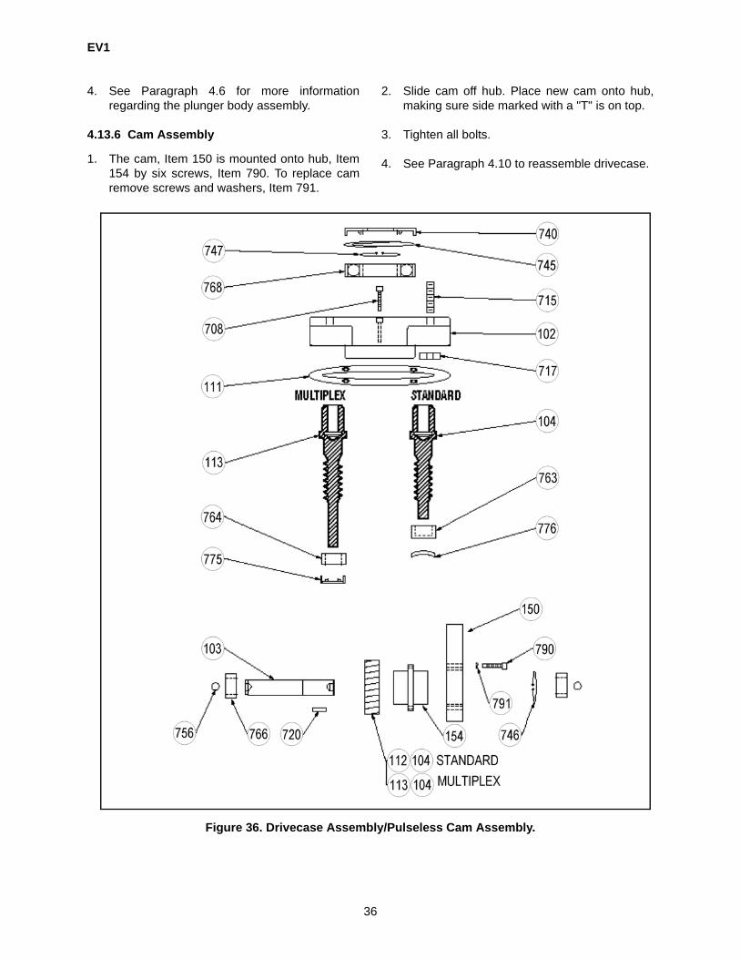
EV1
36
4. See Paragraph 4.6 for more informationregarding the plunger body assembly.
4.13.6 Cam Assembly
1. The cam, Item 150 is mounted onto hub, Item154 by six screws, Item 790. To replace camremove screws and washers, Item 791.
2. Slide cam off hub. Place new cam onto hub,making sure side marked with a "T" is on top.
3. Tighten all bolts.
4. See Paragraph 4.10 to reassemble drivecase.
Figure 36. Drivecase Assembly/Pulseless Cam Assembly.

EV1
37
Figure 37. Pulse-Less Plunger Assembly.
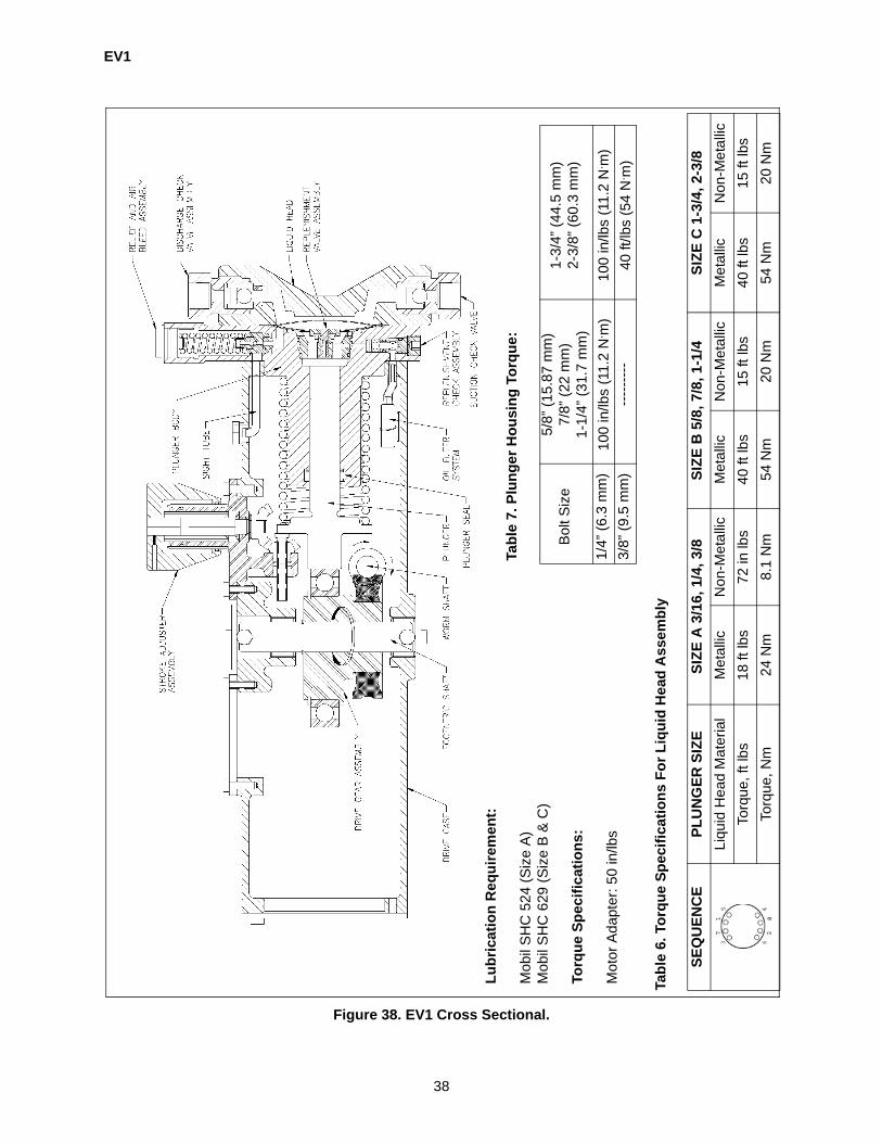
EV1
38
Figure 38. EV1 Cross Sectional.
Lubr
icat
ion
Req
uire
men
t:
Mob
il S
HC
524
(Siz
e A
)M
obil
SH
C 6
29 (S
ize
B &
C)
Torq
ue S
peci
ficat
ions
:
Mot
or A
dapt
er: 5
0 in
/lbs
Tabl
e 7.
Plu
nger
Hou
sing
Tor
que:
Bol
t Siz
e5/
8” (1
5.87
mm
)7/
8” (2
2 m
m)
1-1/
4” (3
1.7
mm
)
1-3/
4” (4
4.5
mm
)2-
3/8”
(60.
3 m
m)
1/4”
(6.3
mm
)10
0 in
/lbs
(11.
2 N
. m)
100
in/lb
s (1
1.2
N. m
)3/
8” (9
.5 m
m)
----
----
-40
ft/lb
s (5
4 N
. m)
Tabl
e 6.
Tor
que
Spec
ifica
tions
For
Liq
uid
Hea
d A
ssem
bly
SEQ
UEN
CE
PLU
NG
ER S
IZE
SIZE
A 3
/16,
1/4
, 3/8
SIZE
B 5
/8, 7
/8, 1
-1/4
SIZE
C 1
-3/4
, 2-3
/8Li
quid
Hea
d M
ater
ial
Met
allic
Non
-Met
allic
Met
allic
Non
-Met
allic
Met
allic
Non
-Met
allic
Torq
ue, f
t lbs
18 ft
lbs
72 in
lbs
40 ft
lbs
15 ft
lbs
40 ft
lbs
15 ft
lbs
Torq
ue, N
m24
Nm
8.1
Nm
54 N
m20
Nm
54 N
m20
Nm

EV1
39
SECTION 5TROUBLESHOOTING
No Flow • Motor not operating - 1. Check motor wiring 2. Check for power.• Suction or discharge valve not open completely - Ensure valves are completely
open.• Velocity too low with slurries - Decrease pipe ID.• Vapor lock in suction line or liquid end - 1. Bleed vapor out of pipe and/or pump. 2.
Check NPSH.• Line, strainer, or check valves clogged - 1. Ensure lines, fittings, and strainers are
clean. 2. Flush slurries and increase filter maintenance on precipitating products.• Hydraulics not primed - Re-prime hydraulics.• Improper action of pressure relief - Inspect and adjust relief valve.
Low Flow • Motor speed wrong - Check motor tag vs. pump tag.• Motor operating at wrong frequency - Check motor tag vs. pump tag.• Velocity too low with slurries - Decrease pipe ID.• Suction line leak - Ensure tight connections.• High velocity in suction or discharge line - 1. Increase pipe ID. 2. Calculate NPSH• Line, strainer, or check valves clogged - 1. Ensure lines, fittings, and strainers are
clean. 2. Flush slurries and increase filter maintenance on precipitating products.• Hydraulics not primed - Re-prime hydraulics.• Piston seal worn - Renew seal.• Punctured Diaphragm - 1. DISASSEMBLE PUMP 2. Replace Diaphragm.
3. Thoroughly check for gear box contamination or damage.• Insufficient NPSH (Starved Suction) - Calculate NPSH.• Gear box oil contaminated - 1. Change oil. 2. Replace filter. 3. Find possible con-
tamination path.• Improper action of pressure relief - Inspect and adjust relief valve.• Improper action of replenishment valve - Inspect, repair, or replace valve.• Improper assembly of stroke adjuster - Inspect and realign.
Erratic Flow • Erratic motor speed - 1. Check motor wiring 2. Check supply power.• Velocity too low with slurries - Decrease pipe ID.• Suction line leak - Ensure tight connections.• Pump not mounted level (Airbound) - Shim base plate.• Pressure on suction varying - Ensure stable suction conditions for accurate pump-
ing.• High velocity in suction or discharge line - 1. Increase pipe ID. 2. Calculate NPSH• Line, strainer, or check valves clogged - 1. Ensure lines, fittings, and strainers are
clean. 2. Flush slurries and increase filter maintenance on precipitating products.• Hydraulics not primed - Re-prime hydraulics.• Piston seal worn - Renew seal.• Punctured Diaphragm - 1. DISASSEMBLE PUMP 2. Replace Diaphragm.
3. Thoroughly check for gear box contamination or damage.• Insufficient NPSH (Starved Suction) - Calculate NPSH.• Insufficient differential pressure - Install back pressure valve.• Gear box oil contaminated - 1. Change oil. 2. Replace filter. 3. Find possible con-
tamination path.• Improper action of pressure relief - Inspect and adjust relief valve.• Improper action of replenishment valve - Inspect, repair, or replace valve.

EV1
40
Flow Gradually Drops
• Velocity too low with slurries - Decrease pipe ID.• Suction line leak - Ensure tight connections.• Vapor lock in suction line or liquid end - 1. Bleed vapor out of pipe and/or pump. 2.
Check NPSH.• Pump not mounted level (Airbound) - Shim base plate.• Line, strainer, or check valves clogged - 1. Ensure lines, fittings, and strainers are
clean. 2. Flush slurries and increase filter maintenance on precipitating products.• Piston seal worn - Renew seal.• Low oil level - Fill gear box and find leak path.• Gear box oil contaminated - 1. Change oil. 2. Replace filter. 3. Find possible con-
tamination path.• Hydraulics air bound - Clean or replace air bleed valve.• Improper action of replenishment valve - Inspect, repair, or replace valve.
Uncontrollable Flow
• Erratic motor speed - 1. Check motor wiring 2. Check supply power.• Velocity too low with slurries - Decrease pipe ID• Pressure on suction varying - Ensure stable suction conditions for accurate pump-
ing.• High velocity in suction or discharge line - 1. Increase pipe ID. 2. Calculate NPSH• Line, strainer, or check valves clogged - 1. Ensure lines, fittings, and strainers are
clean. 2. Flush slurries and increase filter maintenance on precipitating products.• Piston seal worn - Renew seal.• Insufficient differential pressure - Install back pressure valve.• Improper action of replenishment valve - Inspect, repair, or replace valve.• Improper assembly of stroke adjuster - Inspect and realign.
High Flow • Motor speed wrong - Check motor tag vs. pump tag.• Motor operating at wrong frequency - Check motor tag vs. pump tag.• Pressure on suction varying - Ensure stable suction conditions for accurate pump-
ing.• High velocity in suction or discharge line - 1. Increase pipe ID. 2. Calculate NPSH• Insufficient differential pressure - Install back pressure valve.
Check Valve Chatter
• Suction or discharge valve not open completely - Ensure valves are completely open.
• Pump not mounted level (Airbound) - Shim base plate.• Pressure on suction varying - Ensure stable suction conditions for accurate pump-
ing.• High velocity in suction or discharge line - 1. Increase pipe ID. 2. Calculate NPSH• Line, strainer, or check valves clogged - 1. Ensure lines, fittings, and strainers are
clean. 2. Flush slurries and increase filter maintenance on precipitating products.• Insufficient NPSH (Starved Suction) - Calculate NPSH.• Insufficient differential pressure - Install back pressure valve.
Excessive Gear Box Noise
• Motor speed wrong - Check motor tag vs. pump tag.• Punctured Diaphragm - 1. DISASSEMBLE PUMP 2. Replace Diaphragm.
3. Thoroughly check for gear box contamination or damage.• Low oil level - Fill gear box and find leak path.• Gear box oil contaminated - 1. Change oil. 2. Replace filter. 3. Find possible con-
tamination path.• Worn gearing or bearings. - 1. Replace gears or bearings. 2. Locate cause of pos-
sible damage.• Leaking gaskets on gear box - 1. Replace gaskets. 2. Look for possible damage.

EV1
41
Pipe Hammer • Suction or discharge valve not open completely - Ensure valves are completely open.
• High velocity in suction or discharge line - 1. Increase pipe ID. 2. Calculate NPSH• Insufficient NPSH (Starved Suction) - Calculate NPSH.
Motor Over-heating or Noisy
• Motor speed wrong - Check motor tag vs. pump tag.• Motor operating at wrong frequency - Check motor tag vs. pump tag.• Punctured Diaphragm - 1. DISASSEMBLE PUMP 2. Replace Diaphragm.
3. Thoroughly check for gear box contamination or damage.• Low oil level - Fill gear box and find leak path.• Gear box oil contaminated - 1. Change oil. 2. Replace filter. 3. Find possible con-
tamination path.• Worn gearing or bearings. - 1. Replace gears or bearings. 2. Locate cause of pos-
sible damage.• Leaking gaskets on gear box - 1. Replace gaskets. 2. Look for possible damage.
Oil Level Drops • Punctured Diaphragm - 1. DISASSEMBLE PUMP 2. Replace Diaphragm. 3. Thoroughly check for gear box contamination or damage.
• Leaking gaskets on gear box - 1. Replace gaskets. 2. Look for possible damage.

EV1
42
SECTION 6PARTS LIST
6.1 GENERAL
1. This section gives information regardingreplaceable components. The parts lists beginwith A size liquid ends followed with B and Csize liquid ends and ending with parts commonto all size liquid ends.
6.2 ILLUSTRATED PARTS LIST
1. Figure and Item Number Column
a) The item numbers shown in the detailedparts list correspond to the item numbersappearing on the exploded view illustra-tion. To find an unknown part number,locate the part on the illustration and notethe item number. Look for the item numberon the detailed parts list. The part numberis on the same line. A dash (-) precedesnon-illustrated item numbers.
2. Description Column
a) The name of the item is in the descriptioncolumn.
3. Part Number Column
a) The supplier’s part number is listed in thepart number column.
4. Quantity Column
a) The numbers appearing in the quantity col-umn are the total quantity of the listed partrequired in its immediate assembly.
5. Plunger Size Code Column
a) This column is used to denote plunger sizevariations among similar components(models) covered by this publication.When the symbol “03D”, “10D”, “28D” etc.is entered in this column, the part is usedonly in the model at which the symbolappears. If the column lists ALL, the part isused in all models.

EV1
43
EV1 SIZE A
(PLUNGER CODES 03D-3/16 in., 04D-1/4 in., & 06D-3/8 in.)
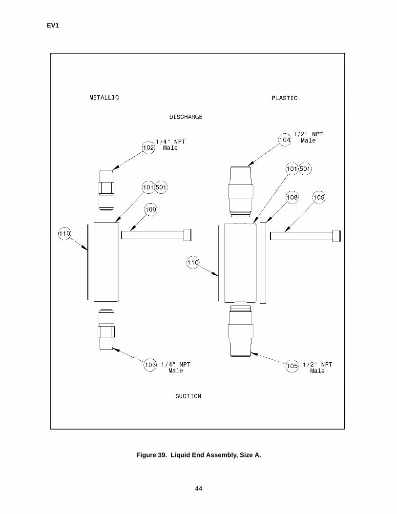
EV1
44
Figure 39. Liquid End Assembly, Size A.

EV1
45
6.3 LIQUID END ASSEMBLY COMPONENTS, SIZE A (316SS, Alloy 20, Hast C, PVC, & KYNAR) (FIGURE 39)
ITEM DESCRIPTION PARTNUMBER
QTY PLUNGER CODE
LIQUID END101 Liquid Head Size A, 316SS 6022A-SS 1 03D,04D,06D
Liquid Head Size A, Alloy 20 6022A-A2 1 03D,04D,06D
Liquid Head Size A, Hast C 6022A-HC 1 03D,04D,06D
Liquid Head Size A, PVC 22400 1 03D,04D,06D
Liquid Head Size A, Kynar 22418 1 03D,04D,06D
501 Liquid Head Size A, Leak Detection, 316SS 6022AL-SS 1 03D,04D,06D
Liquid Head Size A, Leak Detection, Alloy 20 6022AL-A2 1 03D,04D,06D
Liquid Head Size A, Leak Detection, Hast C 6022AL-HC 1 03D,04D,06D
Liquid Head Size A, Leak Detection, PVC 22417 1 03D,04D,06D
Liquid Head Size A, Leak Detection, Kynar 22419 1 03D,04D,06D
NON-METALLIC LIQUID END SUPPORT RING108 Stiffner Plate Size A 60220600 1 03D,04D,06D
DIAPHRAGM110 Diaphragm Size A, Gylon 60330200 1 03D,04D,06D
Diaphragm Assy Size A, Leak Detection, Gylon 60330400 1 03D,04D,06D
METALLIC CHECK VALVE, DISCHARGE (DOUBLE BALL ONLY)102 Metallic Check Valve Assy (316SS), Discharge 30734 1 03D,04D,06D
Metallic Check Valve Assy (CA-20), Discharge 30723 1 03D,04D,06D
Metallic Check Valve Assy (HC-22), Discharge 30736 1 03D,04D,06D
METALLIC CHECK VALVE, SUCTION (DOUBLE BALL ONLY)103 Metallic Check Valve Assy (316SS), Suction 30733 1 03D,04D,06D
Metallic Check Valve Assy (CA-20), Suction 30722 1 03D,04D,06D
Metallic Check Valve Assy (HC-22), Suction 30735 1 03D,04D,06D
PLASTIC CHECK VALVE, DISCHARGE (DOUBLE BALL ONLY)104 Plastic Check Valve Assy (PVC), Discharge 22421 1 03D,04D,06D
Plastic Check Valve Assy (Kynar), Discharge 22423 1 03D,04D,06D
PLASTIC CHECK VALVE, SUCTION (DOUBLE BALL ONLY)105 Plastic Check Valve Assy (PVC), Suction 22420 1 03D,04D,06D
Plastic Check Valve Assy (Kynar), Suction 22422 1 03D,04D,06D
LIQUID END BOLT109 Liquid Head Bolt (Metallic) 90223508HT 8 03D,04D,06D
Liquid Head Bolt (Plastic) 41491 8 03D,04D,06D
- Items not shown.
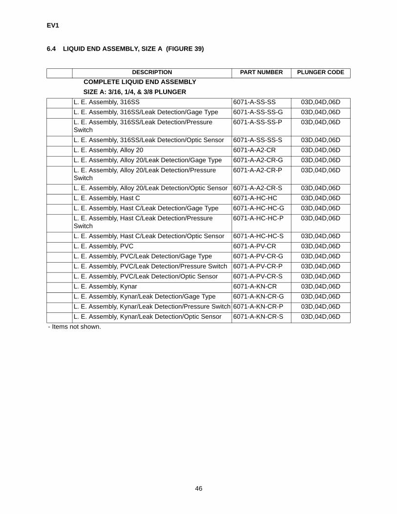
EV1
46
6.4 LIQUID END ASSEMBLY, SIZE A (FIGURE 39)
DESCRIPTION PART NUMBER PLUNGER CODECOMPLETE LIQUID END ASSEMBLYSIZE A: 3/16, 1/4, & 3/8 PLUNGER
L. E. Assembly, 316SS 6071-A-SS-SS 03D,04D,06DL. E. Assembly, 316SS/Leak Detection/Gage Type 6071-A-SS-SS-G 03D,04D,06DL. E. Assembly, 316SS/Leak Detection/Pressure Switch
6071-A-SS-SS-P 03D,04D,06D
L. E. Assembly, 316SS/Leak Detection/Optic Sensor 6071-A-SS-SS-S 03D,04D,06DL. E. Assembly, Alloy 20 6071-A-A2-CR 03D,04D,06DL. E. Assembly, Alloy 20/Leak Detection/Gage Type 6071-A-A2-CR-G 03D,04D,06DL. E. Assembly, Alloy 20/Leak Detection/Pressure Switch
6071-A-A2-CR-P 03D,04D,06D
L. E. Assembly, Alloy 20/Leak Detection/Optic Sensor 6071-A-A2-CR-S 03D,04D,06DL. E. Assembly, Hast C 6071-A-HC-HC 03D,04D,06DL. E. Assembly, Hast C/Leak Detection/Gage Type 6071-A-HC-HC-G 03D,04D,06DL. E. Assembly, Hast C/Leak Detection/Pressure Switch
6071-A-HC-HC-P 03D,04D,06D
L. E. Assembly, Hast C/Leak Detection/Optic Sensor 6071-A-HC-HC-S 03D,04D,06DL. E. Assembly, PVC 6071-A-PV-CR 03D,04D,06DL. E. Assembly, PVC/Leak Detection/Gage Type 6071-A-PV-CR-G 03D,04D,06DL. E. Assembly, PVC/Leak Detection/Pressure Switch 6071-A-PV-CR-P 03D,04D,06DL. E. Assembly, PVC/Leak Detection/Optic Sensor 6071-A-PV-CR-S 03D,04D,06DL. E. Assembly, Kynar 6071-A-KN-CR 03D,04D,06DL. E. Assembly, Kynar/Leak Detection/Gage Type 6071-A-KN-CR-G 03D,04D,06DL. E. Assembly, Kynar/Leak Detection/Pressure Switch 6071-A-KN-CR-P 03D,04D,06DL. E. Assembly, Kynar/Leak Detection/Optic Sensor 6071-A-KN-CR-S 03D,04D,06D
- Items not shown.
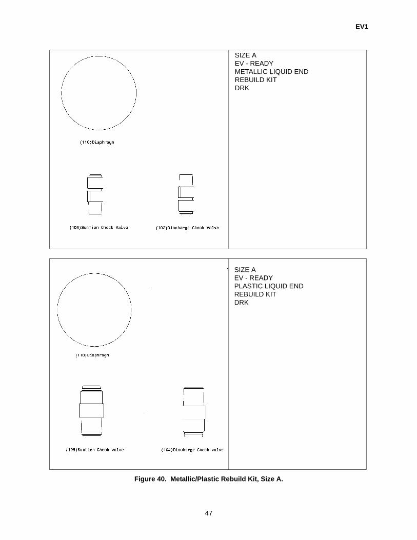
EV1
47
Figure 40. Metallic/Plastic Rebuild Kit, Size A.
SIZE A EV - READYMETALLIC LIQUID ENDREBUILD KITDRK
SIZE A EV - READYPLASTIC LIQUID ENDREBUILD KITDRK
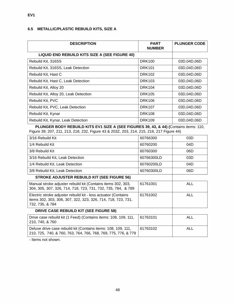
EV1
48
6.5 METALLIC/PLASTIC REBUILD KITS, SIZE A
DESCRIPTION PARTNUMBER
PLUNGER CODE
LIQUID END REBUILD KITS SIZE A (SEE FIGURE 40)Rebuild Kit, 316SS DRK100 03D,04D,06D
Rebuild Kit, 316SS, Leak Detection DRK101 03D,04D,06D
Rebuild Kit, Hast C DRK102 03D,04D,06D
Rebuild Kit, Hast C, Leak Detection DRK103 03D,04D,06D
Rebuild Kit, Alloy 20 DRK104 03D,04D,06D
Rebuild Kit, Alloy 20, Leak Detection DRK105 03D,04D,06D
Rebuild Kit, PVC DRK106 03D,04D,06D
Rebuild Kit, PVC, Leak Detection DRK107 03D,04D,06D
Rebuild Kit, Kynar DRK108 03D,04D,06D
Rebuild Kit, Kynar, Leak Detection DRK109 03D,04D,06D
PLUNGER BODY REBUILD KITS EV1 SIZE A (SEE FIGURES 39, 43, & 44) (Contains items: 110, Figure 39; 207, 211, 213, 218, 232, Figure 43 & 203Z, 203, 214, 215, 216, 217 Figure 44)
3/16 Rebuild Kit 60766300 03D
1/4 Rebuild Kit 60760200 04D
3/8 Rebuild Kit 60760300 06D
3/16 Rebuild Kit, Leak Detection 60766300LD 03D
1/4 Rebuild Kit, Leak Detection 60760200LD 04D
3/8 Rebuild Kit, Leak Detection 60760300LD 06D
STROKE ADJUSTER REBUILD KIT (SEE FIGURE 56)Manual stroke adjuster rebuild kit (Contains items 302, 303, 304, 305, 307, 326, 714, 718, 723, 731, 732, 735, 784, & 789
61761001 ALL
Electric stroke adjuster rebuild kit - less actuator (Contains items 302, 303, 306, 307, 322, 323, 326, 714, 718, 723, 731, 732, 735, & 784
61761002 ALL
DRIVE CASE REBUILD KIT (SEE FIGURE 58)Drive case rebuild kit (1 Feed) (Contains items: 108, 109, 111, 210, 740, & 760
61763101 ALL
Deluxe drive case rebuild kit (Contains items: 108, 109, 111, 210, 725, 740, & 760, 763, 764, 766, 768, 769, 775, 776, & 779
61763102 ALL
- Items not shown.

EV1
49
Figure 41. Metallic Leak Detection, Size A.
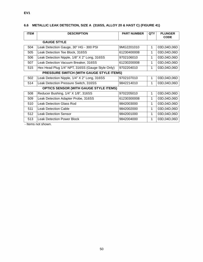
EV1
50
6.6 METALLIC LEAK DETECTION, SIZE A (316SS, ALLOY 20 & HAST C) (FIGURE 41)
ITEM DESCRIPTION PART NUMBER QTY PLUNGER CODE
GAUGE STYLE504 Leak Detection Gauge, 30” HG - 300 PSI 9MG2201010 1 03D,04D,06D505 Leak Detection Tee Block, 316SS 61230400008 1 03D,04D,06D506 Leak Detection Nipple, 1/8” X 2” Long, 316SS 9702106010 1 03D,04D,06D507 Leak Detection Vacuum Breaker, 316SS 61230200008 1 03D,04D,06D515 Hex Head Plug 1/4” NPT, 316SS (Gauge Style Only) 9702204010 1 03D,04D,06D
PRESSURE SWITCH (WITH GAUGE STYLE ITEMS)502 Leak Detection Nipple, 1/4” X 2” Long, 316SS 9702107010 1 03D,04D,06D514 Leak Detection Pressure Switch, 316SS 9842214010 1 03D,04D,06D
OPTICS SENSOR (WITH GAUGE STYLE ITEMS)508 Reducer Bushing, 1/4” X 1/8”, 316SS 9702205010 1 03D,04D,06D509 Leak Detection Adapter Probe, 316SS 61230300008 1 03D,04D,06D510 Leak Detection Glass Rod 9842003000 1 03D,04D,06D511 Leak Detection Cable 9842002000 1 03D,04D,06D512 Leak Detection Sensor 9842001000 1 03D,04D,06D513 Leak Detection Power Block 9842004000 1 03D,04D,06D
- Items not shown.

EV1
51
Figure 42. Non-Metallic Leak Detection, Size A.

EV1
52
6.7 NON-METALLIC LEAK DETECTION, SIZE A (PVC & KYNAR)(FIGURE 42)
ITEM DESCRIPTION PART NUMBER QTY PLUNGER CODE
GAUGE STYLE504 Leak Detection Gauge, 30 HG - 300 PSI 9MG2201010 1 03D,04D,06D505 Leak Detection Tee Block, 316SS 61230400008 1 03D,04D,06D507 Leak Detection Vacuum Breaker, 316SS 61230200008 1 03D,04D,06D515 Hex Head Plug 1/4” NPT, 316SS (Gauge Style Only) 9702102010 1 03D,04D,06D517 Leak Detection Face Plate Size A, SS 60220600 1 03D,04D,06D518 Leak Detection Tee Adapter, 316SS 61232000008 1 03D,04D,06D519 Leak Detection Adapter Seal, Teflon 61435200 1 03D,04D,06D520 Leak Detection Bleeder Adapter, 316SS 61232100008 1 03D,04D,06D
PRESSURE SWITCH (WITH GAUGE STYLE ITEMS)502 Leak Detection Nipple, 1/4” X 2” Long, 316SS 9702107010 1 03D,04D,06D514 Leak Detection Pressure Switch, 316SS 9842214010 1 03D,04D,06D
OPTICS SENSOR (WITH GAUGE STYLE ITEMS)508 Leak Detection Adapter Probe, 316SS 9702205010 1 03D,04D,06D509 Leak Detection Gauge, 61230300008 1 03D,04D,06D510 Leak Detection Glass Rod 9842003000 1 03D,04D,06D511 Leak Detection Cable 9842002000 1 03D,04D,06D512 Leak Detection Sensor 9842001000 1 03D,04D,06D513 Leak Detection Power Block 9842004000 1 03D,04D,06D
- Items not shown.

EV1
53
Figure 43. Plunger Body Assembly, Size A.
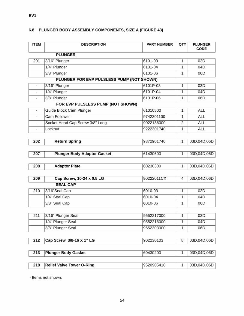
EV1
54
6.8 PLUNGER BODY ASSEMBLY COMPONENTS, SIZE A (FIGURE 43)
ITEM DESCRIPTION PART NUMBER QTY PLUNGER CODE
PLUNGER201 3/16” Plunger 6101-03 1 03D
1/4” Plunger 6101-04 1 04D3/8” Plunger 6101-06 1 06D
PLUNGER FOR EVP PULSLESS PUMP (NOT SHOWN)- 3/16” Plunger 6101P-03 1 03D- 1/4” Plunger 6101P-04 1 04D- 3/8” Plunger 6101P-06 1 06D
FOR EVP PULSLESS PUMP (NOT SHOWN)- Guide Block Cam Plunger 61010500 1 ALL- Cam Follower 9742301100 1 ALL- Socket Head Cap Screw 3/8” Long 9022136000 2 ALL- Locknut 9222301740 1 ALL
202 Return Spring 9372901740 1 03D,04D,06D
207 Plunger Body Adaptor Gasket 61430600 1 03D,04D,06D
208 Adaptor Plate 60230300 1 03D,04D,06D
209 Cap Screw, 10-24 x 0.5 LG 90222011CX 4 03D,04D,06DSEAL CAP
210 3/16”Seal Cap 6010-03 1 03D1/4” Seal Cap 6010-04 1 04D3/8” Seal Cap 6010-06 1 06D
211 3/16” Plunger Seal 9552217000 1 03D1/4” Plunger Seal 9552216000 1 04D3/8” Plunger Seal 9552303000 1 06D
212 Cap Screw, 3/8-16 X 1” LG 902230103 8 03D,04D,06D
213 Plunger Body Gasket 60430200 1 03D,04D,06D
218 Relief Valve Tower O-Ring 9520905410 1 03D,04D,06D
- Items not shown.
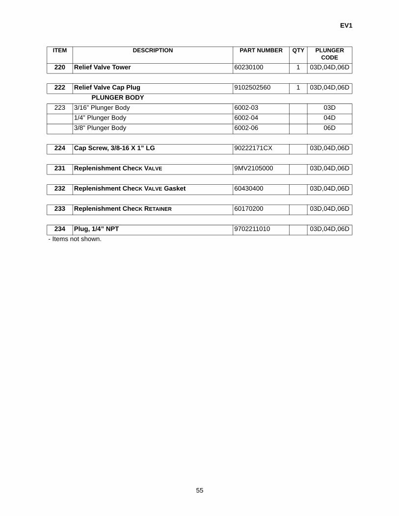
EV1
55
220 Relief Valve Tower 60230100 1 03D,04D,06D
222 Relief Valve Cap Plug 9102502560 1 03D,04D,06DPLUNGER BODY
223 3/16” Plunger Body 6002-03 03D1/4” Plunger Body 6002-04 04D3/8” Plunger Body 6002-06 06D
224 Cap Screw, 3/8-16 X 1” LG 90222171CX 03D,04D,06D
231 Replenishment CheCK VALVE 9MV2105000 03D,04D,06D
232 Replenishment CheCK VALVE Gasket 60430400 03D,04D,06D
233 Replenishment CheCK RETAINER 60170200 03D,04D,06D
234 Plug, 1/4” NPT 9702211010 03D,04D,06D
ITEM DESCRIPTION PART NUMBER QTY PLUNGER CODE
- Items not shown.
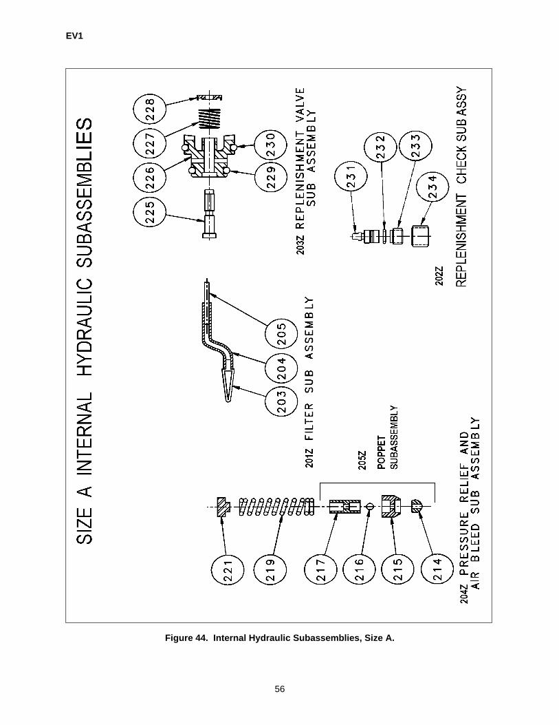
EV1
56
Figure 44. Internal Hydraulic Subassemblies, Size A.

EV1
57
6.9 INTERNAL HYDRAULIC SUBASSEMBLIES, SIZE A (FIGURE 44)
ITEM DESCRIPTION PART NUMBER QTY PLUNGER CODE
FILTER SUBASSEMBLY201Z Filter Subassembly Contains Items: 203, 204, 205 60660100 1 03D,04D,06D203 Filter These Parts are Included in
the Above Subassembly03D,04D,06D
204 Tubing, 3/16” Dia. 03D,04D,06D205 Roll Pin 3/16” Dia X 1-1/4” LG 03D,04D,06D
REPLENISHMENT CHECK SUBASSEMBLY202Z Replenishment Valve Subassembly Contains Items:
231, 232, 233, 23422607 1 03D,04D,06D
231 Check Valve These Parts are Included in the Above Subassembly
03D,04D,06D232 Check Valve Gasket 03D,04D,06D233 Check Retainer 03D,04D,06D234 Plug, 1/4” NPT 03D,04D,06D
REPLENISHMENT VALVE SUBASSEMBLY203Z Replenishment Valve Subassembly Contains Items:
225, 226, 227, 228, 229, 23060752000 1 03D,04D,06D
225 Valve Spool These Parts are Included in the Above Subassembly
03D,04D,06D226 Replenishment Valve Housing 03D,04D,06D227 Replenishment Valve Spring 03D,04D,06D228 Replenishment Valve Head 03D,04D,06D229 Replenishment Valve O-Ring #12 03D,04D,06D230 Replenishment Valve O-Ring #15 03D,04D,06D
PRESSURE RELIEF AND AIR BLEED SUBASSEMBLY204Z Pressure Relief and Air Bleed Assembly Contains
Items: 214, 215, 216, 217, 219, & 221These Parts are Included in the Subassembly Ordered by Spring Number
03D,04D,06D
214 Poppet Ball 03D,04D,06D215 poppet Body 03D,04D,06D216 Air Bleed Ball 03D,04D,06D217 Air Bleed Cap 03D,04D,06D219 Relief Valve Spring 03D,04D,06D
250 PSI Spring (P/N 9372301740) 60750100 1 03D,04D,06D251-900 PSI Spring (P/N 9372302740) 60750101 1 03D,04D,06D901-1300 PSI Spring (P/N 9372303740) 60750102 1 03D,04D,06D1301-1800 PSI Spring (P/N 9372304740) 60750103 1 03D,04D,06D1801-2300 PSI Spring (P/N 9372305740) 60750104 1 03D,04D,06D2301-3500 PSI Spring (P/N 9372306740) 60750105 1 03D,04D,06D
221 Relief Valve Adjusting Nut These Parts are Included in the Subassembly Ordered by Spring Number
03D,04D,06D
- Items not shown.

EV1
58
POPPET SUBASSEMBLY205Z Poppet Subassembly Contains Items: 214, 215, 216, &
217 listed above60751000 1 03D,04D,06D
ITEM DESCRIPTION PART NUMBER QTY PLUNGER CODE
- Items not shown.

EV1
59
6.10 PLUNGER BODY ASSEMBLY, SIZE A (FIGURE 43)
ITEM DESCRIPTION PART NUMBER PLUNGER CODE* Complete Plunger Body Assembly Contains 5 Subassemblies (Figure 44) and All Plunger Body Assembly Components (Figure 43).3/16 Size A 6173-A-03-ES 03D1/4 Size A 6173-A-04-ES 04D3/8 Size A 6173-A-06-ES 06D3/16 Size A, EVP Pulseless Pump 6173-A-03P-ES 03D1/4 Size A, EVP Pulseless Pump 6173-A-04P-ES 04D3/8 Size A, EVP Pulseless Pump 6173-A-06P-ES 06D
RELIEF VALVE SPRING219 250 PSI Spring 9372301740 03D,04D,06D
251-900 PSI Spring 9372302740 03D,04D,06D901-1300 PSI Spring 9372303740 03D,04D,06D1301-1800 PSI Spring 9372304740 03D,04D,06D1801-2300 PSI Spring 9372305740 03D,04D,06D2301-3500 PSI Spring 9372306740 03D,04D,06D
* WHEN ORDERING PLUNGER BODY ASSEMBLY, ORDER RELIEF VALVE SPRING ALSO. SPRING RANGES ARE RELIEF SET PRESSURE.- Items not shown.

EV1
60
EV1 SIZE B
(PLUNGER CODES 10D-5/8 in., 14D-7/8 in., & 20D-1 1/4 in.)

EV1
61
Figure 45. Liquid End Assembly, Size B, Metallic.
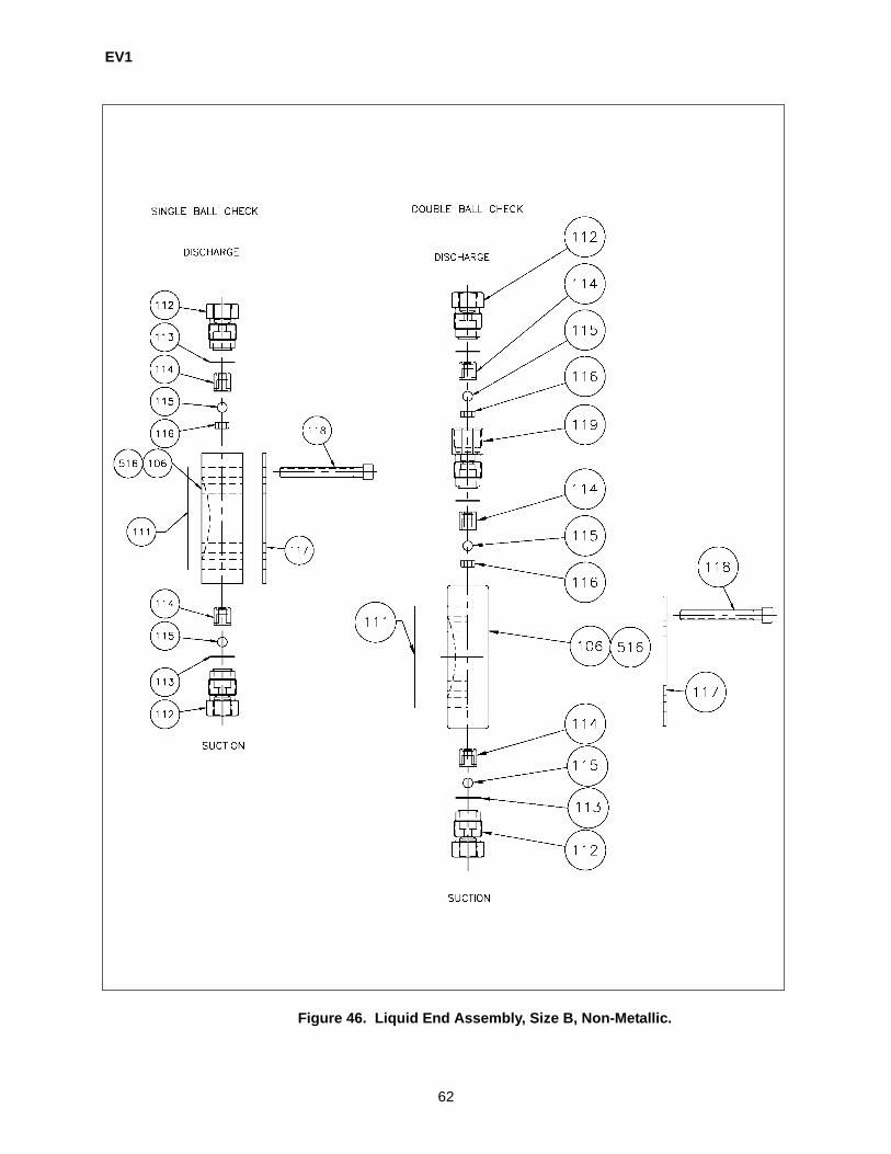
EV1
62
Figure 46. Liquid End Assembly, Size B, Non-Metallic.

EV1
63
6.11 LIQUID END ASSEMBLY COMPONENTS, SIZE B (316SS, Alloy 20, Hast C, PVC, & KYNAR) (FIGURE 45 & 46)
ITEM DESCRIPTION PARTNUMBER
QTY QTY DOUBLE
BALL
PLUNGER CODE
LIQUID END106 Liquid Head Size B, 316SS 21898 1 10D,14D,20D
Liquid Head Size B, Alloy 20 21900 1 10D,14D,20DLiquid Head Size B, Hast C 21937 1 10D,14D,20DLiquid Head Size B, PVC 21939 1 10D,14D,20DLiquid Head Size B, Kynar 21941 1 10D,14D,20D
516 Liquid Head Size B, Leak Detection, 316SS 21899 1 10D,14D,20DLiquid Head Size B, Leak Detection, Alloy 20 21936 1 10D,14D,20DLiquid Head Size B, Leak Detection, Hast C 21938 1 10D,14D,20DLiquid Head Size B, Leak Detection, PVC 21940 1 10D,14D,20DLiquid Head Size B, Leak Detection, Kynar 21942 1 10D,14D,20D
DIAPHRAGM111 Diaphragm Size B, Gylon 21999 1 10D,14D,20D
Diaphragm Assy Size B, Leak Detection, Gylon 61332400 1 10D,14D,20DCHECK VALVE SEAL
113 Check valve Seal, Size B, TFE 61431200 2 10D,14D,20DMETALLIC CHECK VALVE, DISCHARGE (DOUBLE BALL ONLY)
120 Metallic Check Valve (316SS), Discharge 22425 1 10D,14D,20DMetallic Check Valve (CA-20), Discharge 22429 1 10D,14D,20DMetallic Check Valve (HC-22), Discharge 22427 1 10D,14D,20D
METALLIC CHECK VALVE, DISCHARGE (SINGLE BALL ONLY)122 SLURRY CK VALVE (316SS), DISCHARGE 22431 1 10D,14D,20D
METALLIC CHECK VALVE, SUCTION (DOUBLE BALL ONLY)121 Metallic Check Valve (316SS), Suction 22424 2 10D,14D,20D
Metallic Check Valve (CA-20), Suction 22428 2 10D,14D,20DMetallic Check Valve (HC-22), Suction 22426 1 10D,14D,20D
METALLIC CHECK VALVE, SUCTION (SINGLE BALL ONLY)123 SLURRY CK VALVE (316SS), SUCTION 22430 1 10D,14D,20D
NON-METALIC LIQUID END SUPPORT RING117 Face Plate, Size B 61221200 1 10D,14D,20D
Leak Detection Face Plate, Size B 61224901 1 10D,14D,20DLIQUID END BOLT
118 Liquid Head Bolt (Metallic) 90223031C4 8 10D,14D,20DLiquid Head Bolt (Plastic) 90223031C4 8 10D,14D,20D
- Items not shown.

EV1
64
PLASTIC CHECK VALVE COMPONENTS (SINGLE OR DOUBLE BALL)PLASTIC CHECK VALVE CAP
112 Check Valve Cap Size B, PVC 6140PB-PV 2 2 10D,14D,20DCheck Valve Cap Size B, Kynar 6140PB-KN 2 2 10D,14D,20D
113 Check valve Seal, Size B, TFE 61431200 2 3 10D,14D,20DPLASTIC CHECK VALVE GUIDE
114 Ball Guide Size B, PVC 6139PB-PV 2 3 10D,14D,20DBall Guide Size B, Kynar 6139PB-KN 2 3 10D,14D,20D
CHECK VALVE BALL, 3/8 OD115 Check Valve Ball Size B, 316SS 4070014112 2 3 10D,14D,20D
Check Valve Ball Size B, Ceramic 4070015111 2 3 10D,14D,20DCheck Valve Ball Size B, Hast C 4070014116 2 3 10D,14D,20D
PLASTIC CHECK VALVE SEAT116 Check Valve Seat Size B, PVC 6137PB-PV 2 3 10D,14D,20D
Check Valve Seat Size B, Kynar 6137PB-KN 2 3 10D,14D,20DPLASTIC CHECK VALVE DOUBLE BALL BODY
119 Double Ball Body Size B, PVC 6141PB-PV N/A 1 10D,14D,20DDouble Ball Body Size B, Kynar 6141PB-KN N/A 1 10D,14D,20D
ITEM DESCRIPTION PARTNUMBER
QTY QTY DOUBLE
BALL
PLUNGER CODE

EV1
65
6.12 LIQUID END ASSEMBLY, SIZE B (FIGURE 45 & 46)
DESCRIPTION PART NUMBER PLUNGER CODECOMPLETE LIQUID END ASSEMBLYSIZE B: 5/8, 7/8, 1-1/4 PLUNGER
L. E. Assembly, 316SS 6171-B-SS-SS 10D,14D,20DL. E. Assembly, 316SS/Leak Detection/Gage Type 6171-B-SS-SS-G 10D,14D,20DL. E. Assembly, 316SS/Leak Detection/Pressure Switch 6171-B-SS-SS-P 10D,14D,20DL. E. Assembly, 316SS/Leak Detection/Optic Sensor 6171-B-SS-SS-S 10D,14D,20DL. E. Assembly, Alloy 20 6171-B-A2-CR 10D,14D,20DL. E. Assembly, Alloy 20/Leak Detection/Gage Type 6171-B-A2-CR-G 10D,14D,20DL. E. Assembly, Alloy 20/Leak Detection/Pressure Switch
6171-B-A2-CR-P 10D,14D,20D
L. E. Assembly, Alloy 20/Leak Detection/Optic Sensor 6171-B-A2-CR-S 10D,14D,20DL. E. Assembly, Hast C 6171-B-HC-HC 10D,14D,20DL. E. Assembly, Hast C/Leak Detection/Gage Type 6171-B-HC-HC-G 10D,14D,20DL. E. Assembly, Hast C/Leak Detection/Pressure Switch 6171-B-HC-HC-P 10D,14D,20DL. E. Assembly, Hast C/Leak Detection/Optic Sensor 6171-B-HC-HC-S 10D,14D,20DL. E. Assembly, PVC 6171-B-PV-CR 10D,14D,20DL. E. Assembly, PVC/Leak Detection/Gage Type 6171-B-PV-CR-G 10D,14D,20DL. E. Assembly, PVC/Leak Detection/Pressure Switch 6171-B-PV-CR-P 10D,14D,20DL. E. Assembly, PVC/Leak Detection/Optic Sensor 6171-B-PV-CR-S 10D,14D,20DL. E. Assembly, Kynar 6171-B-KN-CR 10D,14D,20DL. E. Assembly, Kynar/Leak Detection/Gage Type 6171-B-KN-CR-G 10D,14D,20DL. E. Assembly, Kynar/Leak Detection/Pressure Switch 6171-B-KN-CR-P 10D,14D,20DL. E. Assembly, Kynar/Leak Detection/Optic Sensor 6171-B-KN-CR-S 10D,14D,20DL. E. Assembly, 316SS, SLURRY 6171-B-SS-TC-SC 10D,14D,20D
- Items not shown.

EV1
66
Figure 47. Metallic/Plastic Rebuild Kit, Size B.
SIZE B EV - READYMETALLIC LIQUID ENDREBUILD KITDRK
SIZE B EV - READYPLASTIC LIQUID ENDREBUILD KITDRK

EV1
67
6.13 METALLIC/PLASTIC REBUILD KITS, SIZE B (FIGURE 47)
DESCRIPTION PARTNUMBER
PLUNGER CODE
LIQUID END REBUILD KITS SIZE B (SEE FIGURE 47)Rebuild Kit, 316SS DRK110 10D,14D,20D
Rebuild Kit, 316SS, Leak Detection DRK111 10D,14D,20D
Rebuild Kit, Hast C DRK112 10D,14D,20D
Rebuild Kit, Hast C, Leak Detection DRK113 10D,14D,20D
Rebuild Kit, Alloy 20 DRK114 10D,14D,20D
Rebuild Kit, Alloy 20, Leak Detection DRK115 10D,14D,20D
Rebuild Kit, Slurry DRK116 10D,14D,20D
Rebuild Kit, Slurry, Leak Detection DRK117 10D,14D,20D
Rebuild Kit, PVC DRK118 10D,14D,20D
Rebuild Kit, PVC, Leak Detection DRK119 10D,14D,20D
Rebuild Kit, Kynar DRK120 10D,14D,20D
Rebuild Kit, Kynar, Leak Detection DRK121 10D,14D,20D
PLUNGER BODY REBUILD KITS EV1 SIZE B (SEE FIGURE 47)(SEE FIGURES 45, 46, 53, & 54) (Contains items: 111, Figure 45 & 46; 210, 709, 737, 777, 779, Figure 53 & 201Z, 202Z, 203Z, 204Z, 205Z Figure 54)
5/8 Rebuild Kit 61760010 10D
7/8 Rebuild Kit 61760700 14D
1-1/4 Rebuild Kit 61760120 20D
5/8 Rebuild Kit, Leak Detection 61760010LD 10D
7/8 Rebuild Kit, Leak Detection 61760700LD 14D
1-1/4 Rebuild Kit, Leak Detection 61760120LD 20D
STROKE ADJUSTER REBUILD KIT (SEE FIGURE 56)Manual stroke adjuster rebuild kit (Contains items 302, 303, 304, 305, 307, 326, 714, 718, 723, 731, 732, 735, & 784
61761001 ALL
Electric stroke adjuster rebuild kit - less actuator (Contains items 302, 303, 306, 307, 322, 323, 326, 714, 718, 723, 731, 732, 735, & 784
61761002 ALL
DRIVE CASE REBUILD KIT (SEE FIGURE 58)Drive case rebuild kit (1 Feed) (Contains items: 108, 109, 111, 210, 740, & 760
61763101 ALL
Deluxe drive case rebuild kit (Contains items: 108, 109, 111, 210, 725, 740, & 760, 763, 764, 766, 768, 769, 775, 776, & 779
61763102 ALL
- Items not shown.

EV1
68
EV1 SIZE C
(PLUNGER CODES 28D-1-3/4 in., 38D-2 3/8 in.)

EV1
69
Figure 48. Liquid End Assembly, Size C, Metallic.
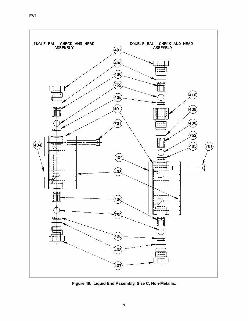
EV1
70
Figure 49. Liquid End Assembly, Size C, Non-Metallic.
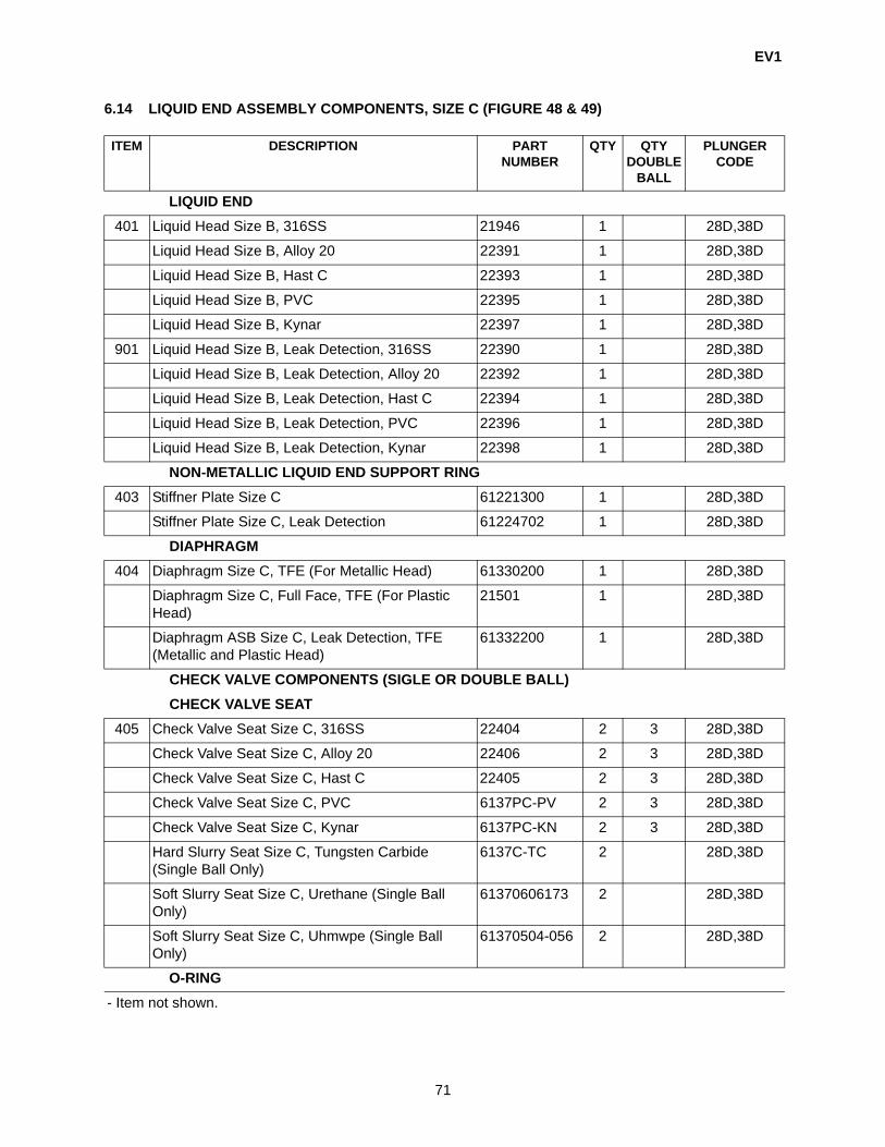
EV1
71
6.14 LIQUID END ASSEMBLY COMPONENTS, SIZE C (FIGURE 48 & 49)
ITEM DESCRIPTION PARTNUMBER
QTY QTYDOUBLE
BALL
PLUNGER CODE
LIQUID END401 Liquid Head Size B, 316SS 21946 1 28D,38D
Liquid Head Size B, Alloy 20 22391 1 28D,38D
Liquid Head Size B, Hast C 22393 1 28D,38D
Liquid Head Size B, PVC 22395 1 28D,38D
Liquid Head Size B, Kynar 22397 1 28D,38D
901 Liquid Head Size B, Leak Detection, 316SS 22390 1 28D,38D
Liquid Head Size B, Leak Detection, Alloy 20 22392 1 28D,38D
Liquid Head Size B, Leak Detection, Hast C 22394 1 28D,38D
Liquid Head Size B, Leak Detection, PVC 22396 1 28D,38D
Liquid Head Size B, Leak Detection, Kynar 22398 1 28D,38D
NON-METALLIC LIQUID END SUPPORT RING403 Stiffner Plate Size C 61221300 1 28D,38D
Stiffner Plate Size C, Leak Detection 61224702 1 28D,38D
DIAPHRAGM404 Diaphragm Size C, TFE (For Metallic Head) 61330200 1 28D,38D
Diaphragm Size C, Full Face, TFE (For Plastic Head)
21501 1 28D,38D
Diaphragm ASB Size C, Leak Detection, TFE (Metallic and Plastic Head)
61332200 1 28D,38D
CHECK VALVE COMPONENTS (SIGLE OR DOUBLE BALL)CHECK VALVE SEAT
405 Check Valve Seat Size C, 316SS 22404 2 3 28D,38D
Check Valve Seat Size C, Alloy 20 22406 2 3 28D,38D
Check Valve Seat Size C, Hast C 22405 2 3 28D,38D
Check Valve Seat Size C, PVC 6137PC-PV 2 3 28D,38D
Check Valve Seat Size C, Kynar 6137PC-KN 2 3 28D,38D
Hard Slurry Seat Size C, Tungsten Carbide (Single Ball Only)
6137C-TC 2 28D,38D
Soft Slurry Seat Size C, Urethane (Single Ball Only)
61370606173 2 28D,38D
Soft Slurry Seat Size C, Uhmwpe (Single Ball Only)
61370504-056 2 28D,38D
O-RING- Item not shown.

EV1
72
402 O-Ring, TFE Encapsulated Viton (For Metallic Head Only)
41486 2 3 28D,38D
CHECK VALVE GUIDE406 Ball Guide Size C, 316SS 6139C-SS 2 3 28D,38D
Ball Guide Size C, Alloy 20 6139C-A2 2 3 28D,38D
Ball Guide Size C, Hast C 6139C-HC 2 3 28D,38D
Ball Guide Size C, PVC 6139PC-PV 2 3 28D,38D
Ball Guide Size C, Kynar 6139PC-KN 2 3 28D,38D
Slurry Guide Size C Hast C (Single Ball Only) 61390706019 2 28D,38D
CHECK VALVE CAP407 Check Valve Cap, Size C, 316SS 6140C-SS 2 2 28D,38D
Check Valve Cap, Size C, Alloy 20 6140C-A2 2 2 28D,38D
Check Valve Cap, Size C, Hast C 6140C-HC 2 2 28D,38D
Check Valve Cap, Size C, PVC 6140PC-PV 2 2 28D,38D
Check Valve Cap, Size C, Kynar 6140PC-KN 2 2 28D,38D
CHECK VALVE SEAL408 Check Valve Seal, TFE, Metallic Head 61430800 2 3 28D,38D
Check Valve Seal, TFE, Non-Metallic Head 61431300 2 3 28D,38D
DOUBLE BALL TRANSISTION PIECE410 Check Valve Cap, Size C, 316SS 22576 N/A 1 28D,38D
Check Valve Cap, Size C, Alloy 20 22577 N/A 1 28D,38D
Check Valve Cap, Size C, Hast C 22578 N/A 1 28D,38D
Check Valve Cap, Size C, PVC 6141PC-PV N/A 1 28D,38D
Check Valve Cap, Size C, Kynar 6141PC-KN N/A 1 28D,38D
LIQUID HEAD BOLT701 Liquid Head Bolt, Cast Metallic Head 90224011CX 8 8 28D,38D
Liquid Head Bolt, Non-Metallic Head 90224231C4 8 28D,38D
CHECK VALVE BALLCheck Valve Ball Size C, 316SS 4070014192 2 3 28D,38D
Check Valve Ball Size C, Ceramic 4070015191 2 3 28D,38D
Check Valve Ball Size C, Hast c 4070014196 2 3 28D,38D
Check Valve Ball Size C, Tungsten Carbide Ball) 9692508-TC 2 28D,38D
ITEM DESCRIPTION PARTNUMBER
QTY QTYDOUBLE
BALL
PLUNGER CODE
- Item not shown.

EV1
73
6.15 LIQUID END ASSEMBLY, SIZE C (FIGURE 48 & 49)
DESCRIPTION PART NUMBER PLUNGER CODECOMPLETE LIQUID END ASSEMBLYSIZE C: 1-3/4, 2-3/8 PLUNGER
L. E. Assembly, 316SS 6171-C-SS-SS 03D,04D,06DL. E. Assembly, 316SS/Leak Detection/Gage Type 6171-C-SS-SS-G 03D,04D,06DL. E. Assembly, 316SS/Leak Detection/Pressure Switch 6171-C-SS-SS-P 03D,04D,06DL. E. Assembly, 316SS/Leak Detection/Optic Sensor 6171-C-SS-SS-S 03D,04D,06DL. E. Assembly, Alloy 20 6171-C-A2-CR 03D,04D,06DL. E. Assembly, Alloy 20/Leak Detection/Gage Type 6171-C-A2-CR-G 03D,04D,06DL. E. Assembly, Alloy 20/Leak Detection/Pressure Switch 6171-C-A2-CR-P 03D,04D,06DL. E. Assembly, Alloy 20/Leak Detection/Optic Sensor 6171-C-A2-CR-S 03D,04D,06DL. E. Assembly, Hast C 6171-C-HC-HC 03D,04D,06DL. E. Assembly, Hast C/Leak Detection/Gage Type 6171-C-HC-HC-G 03D,04D,06DL. E. Assembly, Hast C/Leak Detection/Pressure Switch 6171-C-HC-HC-P 03D,04D,06DL. E. Assembly, Hast C/Leak Detection/Optic Sensor 6171-C-HC-HC-S 03D,04D,06DL. E. Assembly, PVC 6171-C-PV-CR 03D,04D,06DL. E. Assembly, PVC/Leak Detection/Gage Type 6171-C-PV-CR-G 03D,04D,06DL. E. Assembly, PVC/Leak Detection/Pressure Switch 6171-C-PV-CR-P 03D,04D,06DL. E. Assembly, PVC/Leak Detection/Optic Sensor 6171-C-PV-CR-S 03D,04D,06DL. E. Assembly, Kynar 6171-C-KN-CR 03D,04D,06DL. E. Assembly, Kynar/Leak Detection/Gage Type 6171-C-KN-CR-G 03D,04D,06DL. E. Assembly, Kynar/Leak Detection/Pressure Switch 6171-C-KN-CR-P 03D,04D,06DL. E. Assembly, Kynar/Leak Detection/Optic Sensor 6171-C-KN-CR-S 03D,04D,06DL. E. Assembly,316SS, Slurry 6171-C-SS-TC-SC 03D,04D,06D
- Items not shown.

EV1
74
Figure 50. Metallic/Plastic Rebuild Kit, Size C.
SIZE C EV - READYMETALLIC LIQUID ENDREBUILD KITDRK
SIZE C EV - READYPLASTIC LIQUID ENDREBUILD KITDRK
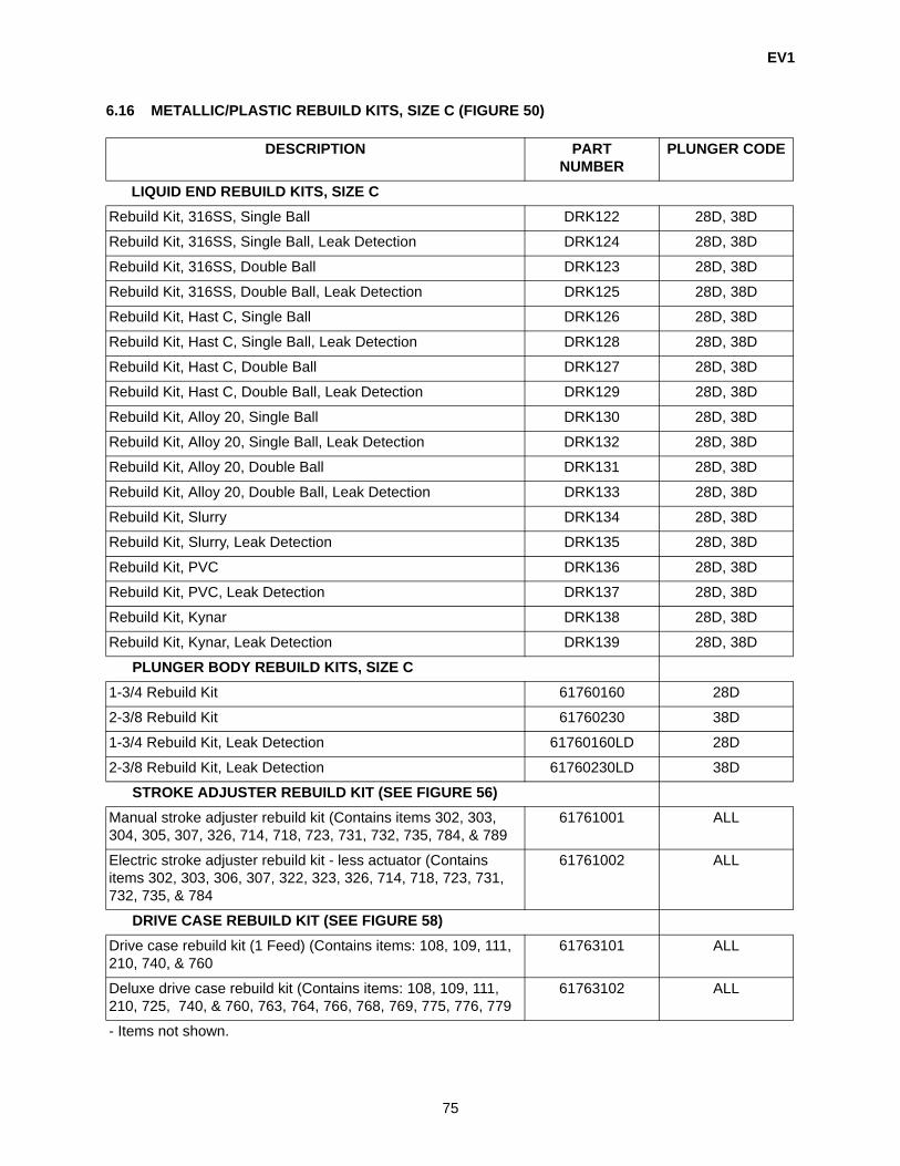
EV1
75
6.16 METALLIC/PLASTIC REBUILD KITS, SIZE C (FIGURE 50)
DESCRIPTION PARTNUMBER
PLUNGER CODE
LIQUID END REBUILD KITS, SIZE CRebuild Kit, 316SS, Single Ball DRK122 28D, 38D
Rebuild Kit, 316SS, Single Ball, Leak Detection DRK124 28D, 38D
Rebuild Kit, 316SS, Double Ball DRK123 28D, 38D
Rebuild Kit, 316SS, Double Ball, Leak Detection DRK125 28D, 38D
Rebuild Kit, Hast C, Single Ball DRK126 28D, 38D
Rebuild Kit, Hast C, Single Ball, Leak Detection DRK128 28D, 38D
Rebuild Kit, Hast C, Double Ball DRK127 28D, 38D
Rebuild Kit, Hast C, Double Ball, Leak Detection DRK129 28D, 38D
Rebuild Kit, Alloy 20, Single Ball DRK130 28D, 38D
Rebuild Kit, Alloy 20, Single Ball, Leak Detection DRK132 28D, 38D
Rebuild Kit, Alloy 20, Double Ball DRK131 28D, 38D
Rebuild Kit, Alloy 20, Double Ball, Leak Detection DRK133 28D, 38D
Rebuild Kit, Slurry DRK134 28D, 38D
Rebuild Kit, Slurry, Leak Detection DRK135 28D, 38D
Rebuild Kit, PVC DRK136 28D, 38D
Rebuild Kit, PVC, Leak Detection DRK137 28D, 38D
Rebuild Kit, Kynar DRK138 28D, 38D
Rebuild Kit, Kynar, Leak Detection DRK139 28D, 38D
PLUNGER BODY REBUILD KITS, SIZE C1-3/4 Rebuild Kit 61760160 28D
2-3/8 Rebuild Kit 61760230 38D
1-3/4 Rebuild Kit, Leak Detection 61760160LD 28D
2-3/8 Rebuild Kit, Leak Detection 61760230LD 38D
STROKE ADJUSTER REBUILD KIT (SEE FIGURE 56)Manual stroke adjuster rebuild kit (Contains items 302, 303, 304, 305, 307, 326, 714, 718, 723, 731, 732, 735, 784, & 789
61761001 ALL
Electric stroke adjuster rebuild kit - less actuator (Contains items 302, 303, 306, 307, 322, 323, 326, 714, 718, 723, 731, 732, 735, & 784
61761002 ALL
DRIVE CASE REBUILD KIT (SEE FIGURE 58)Drive case rebuild kit (1 Feed) (Contains items: 108, 109, 111, 210, 740, & 760
61763101 ALL
Deluxe drive case rebuild kit (Contains items: 108, 109, 111, 210, 725, 740, & 760, 763, 764, 766, 768, 769, 775, 776, 779
61763102 ALL
- Items not shown.

EV1
76
EV1 SIZE B AND C
(PLUNGER CODES 10D-5/8 in., 14D-7/8 in., & 20D-1 1/4 in.)(PLUNGER CODES 28D-1-3/4 in., 38D-2 3/8 in.)

EV1
77
Figure 51. Metallic Leak Detection, Size B and C.

EV1
78
6.17 METALLIC LEAK DETECTION, SIZE B & C (316SS, ALLOY 20 & HAST C) (FIGURE 51)
ITEM DESCRIPTION PART NUMBER QTY PLUNGER CODE
GAUGE STYLE504 Leak Detection Gauge, 30” HG - 300 PSI 9MG2201010 1 10D,14D,20D505 Leak Detection Tee Block, 316SS 61230400008 1 10D,14D,20D506 Leak Detection Nipple, 1/8” X 2” Long, 316SS 9702106010 1 10D,14D,20D507 Leak Detection Vacuum Breaker, 316SS 61230200008 1 10D,14D,20D515 Hex Head Plug 1/4” NPT, 316SS (Gauge Style Only) 9702204010 1 10D,14D,20D
PRESSURE SWITCH (WITH GAUGE STYLE ITEMS)502 Leak Detection Nipple, 1/4” X 2” Long, 316SS 9702107010 1 10D,14D,20D514 Leak Detection Pressure Switch, 316SS 9842214010 1 10D,14D,20D
OPTICS SENSOR (WITH GAUGE STYLE ITEMS)508 Reducer Bushing, 1/4” X 1/8”, 316SS 9702205010 1 10D,14D,20D509 Leak Detection Adapter Probe, 316SS 61230300008 1 10D,14D,20D510 Leak Detection Glass Rod 9842003000 1 10D,14D,20D511 Leak Detection Cable 9842002000 1 10D,14D,20D512 Leak Detection Sensor 9842001000 1 10D,14D,20D513 Leak Detection Power Block 9842004000 1 10D,14D,20D
- Items not shown.

EV1
79
Figure 52. Non-Metallic Leak Detection, Size B and C.
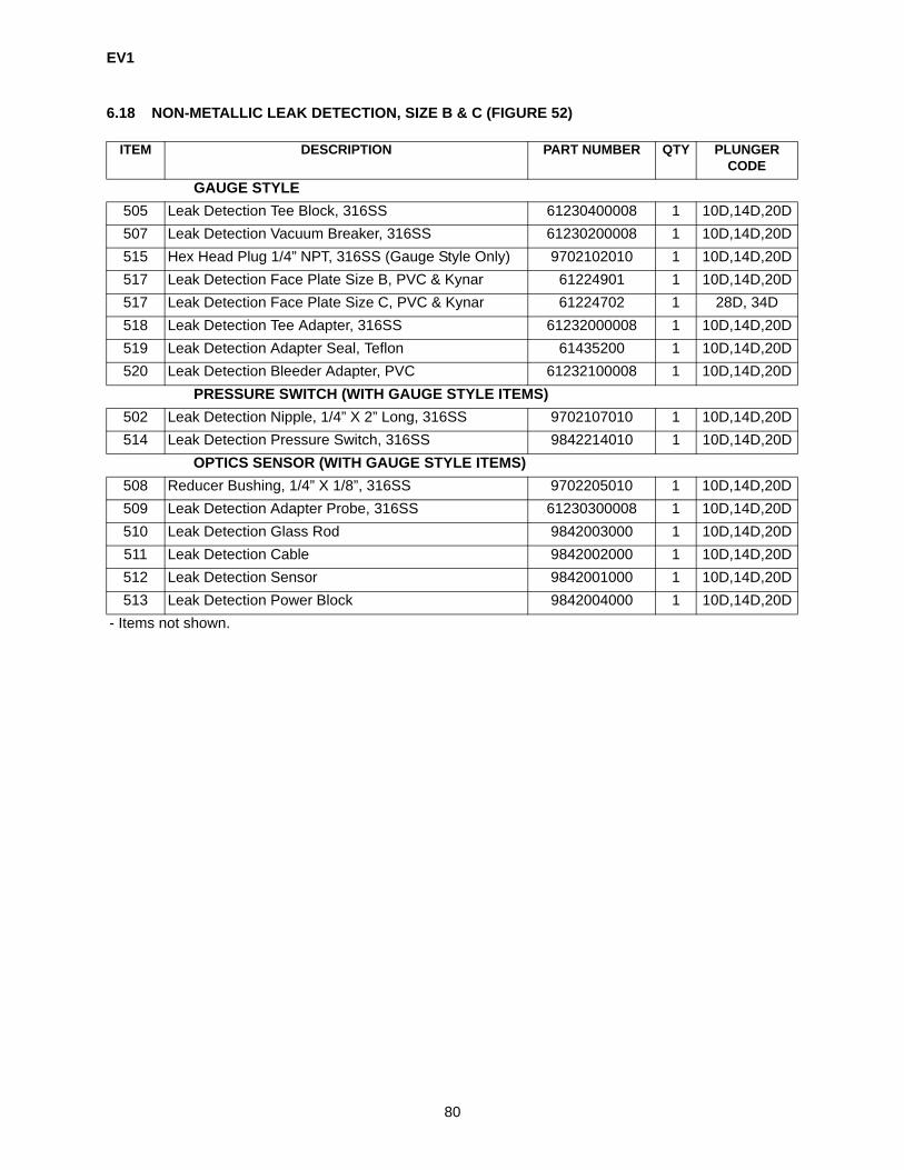
EV1
80
6.18 NON-METALLIC LEAK DETECTION, SIZE B & C (FIGURE 52)
ITEM DESCRIPTION PART NUMBER QTY PLUNGER CODE
GAUGE STYLE505 Leak Detection Tee Block, 316SS 61230400008 1 10D,14D,20D507 Leak Detection Vacuum Breaker, 316SS 61230200008 1 10D,14D,20D515 Hex Head Plug 1/4” NPT, 316SS (Gauge Style Only) 9702102010 1 10D,14D,20D517 Leak Detection Face Plate Size B, PVC & Kynar 61224901 1 10D,14D,20D517 Leak Detection Face Plate Size C, PVC & Kynar 61224702 1 28D, 34D518 Leak Detection Tee Adapter, 316SS 61232000008 1 10D,14D,20D519 Leak Detection Adapter Seal, Teflon 61435200 1 10D,14D,20D520 Leak Detection Bleeder Adapter, PVC 61232100008 1 10D,14D,20D
PRESSURE SWITCH (WITH GAUGE STYLE ITEMS)502 Leak Detection Nipple, 1/4” X 2” Long, 316SS 9702107010 1 10D,14D,20D514 Leak Detection Pressure Switch, 316SS 9842214010 1 10D,14D,20D
OPTICS SENSOR (WITH GAUGE STYLE ITEMS)508 Reducer Bushing, 1/4” X 1/8”, 316SS 9702205010 1 10D,14D,20D509 Leak Detection Adapter Probe, 316SS 61230300008 1 10D,14D,20D510 Leak Detection Glass Rod 9842003000 1 10D,14D,20D511 Leak Detection Cable 9842002000 1 10D,14D,20D512 Leak Detection Sensor 9842001000 1 10D,14D,20D513 Leak Detection Power Block 9842004000 1 10D,14D,20D
- Items not shown.
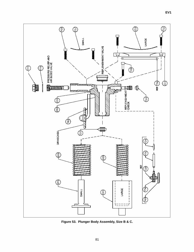
EV1
81
Figure 53. Plunger Body Assembly, Size B & C.

EV1
82
6.19 PLUNGER BODY ASSEMBLY, SIZE B & C (FIGURE 53)
ITEM DESCRIPTION PART NUMBER QTY PLUNGER CODE
PLUNGER201 5/8” Plunger 6101-10 1 10D
7/8” Plunger 6101-14 1 14D1-1/4” Plunger 6101-20 1 20D1-3/4” Plunger 6101-28 1 28D2-3/8 Plunger 6101-38 1 38D
PLUNGER FOR EVP PULSLESS PUMP (NOT SHOWN)- 5/8” Plunger Cam Style 6101P-10 1 10D- 7/8” Plunger Cam Style 6101P-14 1 14D- 1-1/4” Plunger Cam Style 6101P-20 1 20D
1-3/4” Plunger Cam Style 6101P-28 1 28D2-3/8 Plunger Cam Style 6101P-38 1 38D
FOR EVP PULSLESS PUMP (NOT SHOWN)- Guide Block Cam Plunger 61010500 1 ALL- Cam Follower 9742301100 1 ALL- Socket Head Cap Screw 3/8” Long 9022136000 1 ALL- Locknut 9222301740 1 ALL
PLUNGER BODY202 5/8” Plunger Body 21943 1 10D
7/8” Plunger Body 21944 1 14D1-1/4” Plunger Body 21945 1 20D1-3/4” Plunger Body 6102-28-N 1 28D2-3/8 Plunger Body 6102-38-N 1 38D
CONTOUR PLATE RING213 Contour Plate Ring 22399 1 28D, 38D
Contour Plate Ring, Leak Detection 6122190LN 1 28D, 38DSPRING
209 Plunger Return Spring 61420300 1 10D,14D,20D, Plunger Return Spring 61420400 1 28DPlunger Return Spring 61420500 1 38D
210 Plunger Body Gasket 61430600 1 ALLCONTOUR PLATE
212 Contour Plate, Size B 61220312 1 10D,14D,20DContour Plate, Size C 61220800 1 28D, 38D
709 Cap Screw, 1/4” - 20” X 1-1/2” Long 90222A61CX 2 10D,14D,20D712 Cap Screw, 1/4” - 20” X 5/8” Long 90222741CX 2 28D, 38D
- Items not shown.

EV1
83
716 Plastic Cap 9102401000 1 28D, 38D736 Plunger Body O-Ring 9520234410 1 28D, 38D
PLUNGER BODY SEAL737 5/8” Plunger Seal 9552502000 1 10D
7/8” Plunger Seal 9552601000 1 14D1-1/4” Plunger Seal 9552702000 1 20D1-3/4” Plunger Seal 9552901000 1 28D2-3/8 Plunger Seal 9553002000 1 38D
777 Cap Plug 9102501560 1 ALL779 Relief Valve Cap Gasket 9562501000 1 ALL
STANDARD SIGHT TUBE ASSEMBLY781 Vertical A Feed 61890900 1 ALL
Vertical B Feed 61890901 1 ALL
ITEM DESCRIPTION PART NUMBER QTY PLUNGER CODE
- Items not shown.

EV1
84
Figure 54. Plunger Body Internal Hydraulic SubAssemblies, Size B & C.
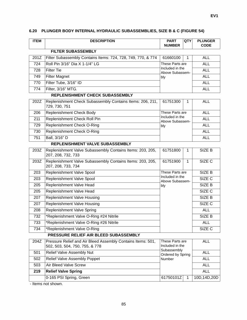
EV1
85
6.20 PLUNGER BODY INTERNAL HYDRAULIC SUBASSEMBLIES, SIZE B & C (FIGURE 54)
ITEM DESCRIPTION PART NUMBER
QTY PLUNGER CODE
FILTER SUBASSEMBLY201Z Filter Subassembly Contains Items: 724, 728, 749, 770, & 774 61660100 1 ALL724 Roll Pin 3/16” Dia X 1-1/4” LG These Parts are
Included in the Above Subassem-bly
ALL728 Filter Tie ALL749 Filter Magnet ALL770 Filter Tube, 3/16” ID ALL774 Filter, 3/16” MTG. ALL
REPLENISHMENT CHECK SUBASSEMBLY202Z Replenishment Check Subassembly Contains Items: 206, 211,
729, 730, 75161751300 1 ALL
206 Replenishment Check Body These Parts are Included in the Above Subassem-bly
ALL211 Replenishment Check Roll Pin ALL729 Replenishment Check O-Ring ALL730 Replenishment Check O-Ring ALL751 Ball, 3/16” D ALL
REPLENISHMENT VALVE SUBASSEMBLY203Z Replenishment Valve Subassembly Contains Items: 203, 205,
207, 208, 732, 73361751800 1 SIZE B
203Z Replenishment Valve Subassembly Contains Items: 203, 205, 207, 208, 733, 734
61751900 1 SIZE C
203 Replenishment Valve Spool These Parts are Included in the Above Subassem-bly
SIZE B203 Replenishment Valve Spool SIZE C205 Replenishment Valve Head SIZE B205 Replenishment Valve Head SIZE C207 Replenishment Valve Housing SIZE B207 Replenishment Valve Housing SIZE C208 Replenishment Valve Spring ALL732 *Replenishment Valve O-Ring #24 Nitrile SIZE B733 *Replenishment Valve O-Ring #26 Nitrile ALL734 *Replenishment Valve O-Ring SIZE C
PRESSURE RELIEF AIR BLEED SUBASSEMBLY204Z Pressure Relief and Air Bleed Assembly Contains Items: 501,
502, 503, 504, 750, 755, & 778These Parts are Included in the Subassembly Ordered by Spring Number
ALL
501 Relief Valve Assembly Nut ALL502 Relief Valve Assembly Poppet ALL503 Air Bleed Valve Screw ALL219 Relief Valve Spring ALL
0-165 PSI Spring, Green 61750101Z 1 10D,14D,20D- Items not shown.

EV1
86
166-330 PSI Spring, Orange 61750201Z 1 10D,14D,20D331-790 PSI Spring, Blue 61750401Z 1 10D,14D,20D791-1694 PSI Spring, Gold 61750301Z 1 10D,14D,20D1695-2000 PSI Spring, Red 61750501Z 1 10D,14D,20D530-740 PSI Spring, Orange 61750201Z 1 10D,14D,20D150-220 PSI Spring, Green 61750101Z 1 28D, 38D330-470 PSI Spring, Orange 61750201Z 1 28D
750 Air Bleed Ball, 7/64” OD These Parts are Included in the Subassembly Ordered by Spring Number
ALL755 Poppet Ball, 5/16” OD ALL778 Alignment Collar ALL
POPPET SUBASSEMBLY205Z Poppet Subassembly Contains Items: 502,503, 750, 755, & 778
listed above61751600 1 ALL
ITEM DESCRIPTION PART NUMBER
QTY PLUNGER CODE
- Items not shown.

EV1
87
6.21 PLUNGER BODY ASSEMBLY, SIZE B & C (FIGURE 53)
ITEM DESCRIPTION PART NUMBER
PLUNGER CODE
* Complete Plunger Body Assembly Contains Items: 201Z, 202Z, 203Z, 204Z, 205Z, 201, 202, 209, 210, 212, 213, 709, 712, 716, 736, 737, 777, 779, & 781
5/8” Plunger 6173-B-10-EN 10D7/8” Plunger 6173-B-14-EN 14D1-1/4” Plunger 6173-B-20-EN 20D1-3/4” Plunger 6173-C-28-EN 28D2-3/8 Plunger 6173-C-38-EN 38D5/8” Plunger, EVP Pulseless Pump 6173-B-10P-EN 10D7/8” Plunger, EVP Pulseless Pump 6173-B-14P-EN 14D1-1/4” Plunger, EVP Pulseless Pump 6173-B-20P-EN 20D1-3/4” Plunger, EVP Pulseless Pump 6173-C-28P-EN 28D2-3/8 Plunger, EVP Pulseless Pump 6173-C-38P-EN 38D
RELIEF VALVE SPRING245 165 PSI Spring 9372003000 10D,14D,20D
166-330 PSI Spring 9372006000 10D,14D,20D331-790 PSI Spring 9372004000 10D,14D,20D791-1694 PSI Spring 9372002000 10D,14D,20D1695-2000 PSI Spring 9372008000 10D,14D,20D0-165 PSI Spring 9372003000 28D166-330 PSI Spring 9372006000 28D0-150 PSI Spring 9372003000 38D
* WHEN ORDERING PLUNGER BODY ASSEMBLY, ORDER RELIEF VALVE SPRING ALSO. SPRING RANGES ARE RELIEF SET PRESSURE.- Items not shown.

EV1
88
PARTS COMMON TO ALL SIZE LIQUID ENDS

EV1
89
Figure 55. Manual Stroke Adjuster Assembly.

EV1
90
6.22 MANUAL STROKE ADJUSTER ASSEMBLY (FIGURE 55)
ITEM DESCRIPTION PART NUMBER QTY PLUNGER CODE
108 Stroke Adjuster Cover Gasket 61430100 1
301 Stroke Adjuster Housing 61070700 1
302 Plunger Stop 61120500 1
303 Stroke Adjuster Sleeve 61120200 1
304 Stroke Adjuster Gear Shaft 61150200 1
305 Stroke Adjuster Shaft Screw 61150300 1
306 Stroke Adjuster Knob 61340101 1
307 Beveled Gear Washer 61430500 1
308 Beveled Pinion 61880300 1
309 Beveled Gear 61880400 1
326 Plunger Stop Bushing 61120700 1
702 Socket Head Cap Screw, 10” - 24” X 7/16” Long 90122061C4 1
714 Set Screw, 8” - 32” X 1/4” Long 90322481CX 1
718 Spring Washer, 11/16 Dia. Curved 9362301030 1
723 Roll Pin, 1/16” X 5/8” 943212374E 1
731 O-Ring, 70 Duro Buna-n 9520012410 1
732 O-Ring, # 24 Nitrile 9520024410 1
735 O-Ring, # 120 70 Duro Buna 9520120410 1
784 Set Screw, 8” - 32” X 1/4” Long Cone Point 90322801C0 2
STROKE ADJUSTER ASSEMBLY300Z Complete Manual Stroke Adjuster Assembly, Contains
Items: 108, 301-309, 326, 702, 714, 718, 723, 731, 732, 735, & 784
6179MN02A 1
- Items not shown.

EV1
91
Figure 56. Electronic Stroke Adjuster Assembly.

EV1
92
6.23 ELECTRONIC STROKE ADJUSTER ASSEMBLY (FIGURE 56)
ITEM DESCRIPTION PART NUMBER QTY PLUNGER CODE
108 Stroke Adjuster Cover Gasket 61430100 1
301 Stroke Adjuster Housing 61070700 1
302 Plunger Stop 61120500 1
303 Stroke Adjuster Sleeve 61120200 1
306 Stroke Adjuster Knob 61340101 1
307 Beveled Gear Washer 61430500 1
308 Beveled Pinion 61880300 1
309 Beveled Gear 61880400 1
322 Gear Shaft, Electric Stroke 61150700
323 Screw shaft, Electric Stroke 61150800
326 Plunger Stop Bushing 61120700 1
702 Screw, 10” - 24” X 3/8” Long 90122061C4 1
714 Set Screw, 8” - 32” X 1/4” Long 90322481CX 1
718 Spring Washer, 11/16 Dia. Curved 9362301030 1
723 Roll Pin, 1/8” X 5/8” 943212374E 1
731 O-Ring, 70 Duro Buna-n 9520012410 1
732 O-Ring, # 24 Nitrile 9520024410 1
735 O-Ring, # 120 70 Duro Buna 9520120410 1
784 Set Screw, 8” - 32” X 1/4” Long Cone Point 90322801C0 2
789 Stroke Adjuster Knob Seal 9MT2201000 1
ACTUATOR ASSEMBLY320 Actuator Bracket 61080900 1
321 Bracket, Horizontal Motor 61081400 1
324 Coupling Guard, 304SS 61870600 1
601 Base Electric Stroke 61062400 1
771 Actuator Coupling 9M42202000 1
781 Screw, 1/4” - 20” X 5/8” Long 90122011CE 4
782 Screw, 3/8” - 16” X 1/2” Long 90223021CX 4
785 Hex Head Cap Screw, 1/4” - 20” X 0.62” Long 90122011CE 4
786 Hex Nut 1/4” - 20” 91922031CE 4
787 Lock Washer 1/4” 935221411E 8
301Z Electric Stroke Adjuster Assembly - Less Actuator, Contains Items: 108, 301, 302, 303, 306, 307, 308, 309, 322, 323, 326, 702, 714, 718, 723, 731, 732, 735, 784, & 789
6179EL02A 1
DuramaticTM Actuator Contains Items: 302, 303, 306, 307, 322, 323, 326, 714, 718, 723, 731, 732, 735, 784
9MA2007000 1
- Items not shown.
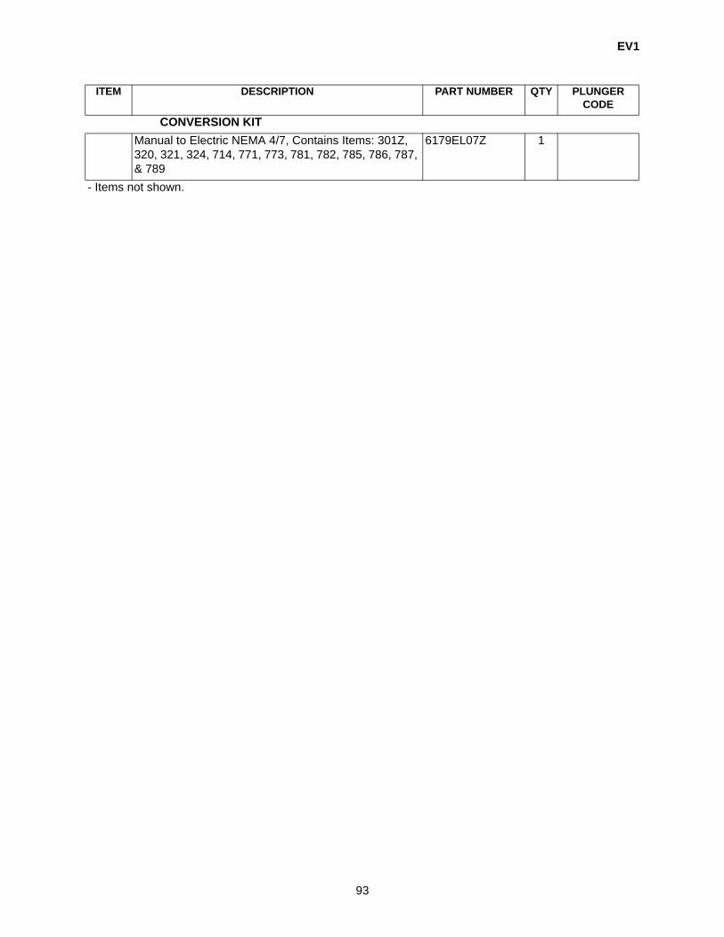
EV1
93
CONVERSION KITManual to Electric NEMA 4/7, Contains Items: 301Z, 320, 321, 324, 714, 771, 773, 781, 782, 785, 786, 787, & 789
6179EL07Z 1
ITEM DESCRIPTION PART NUMBER QTY PLUNGER CODE
- Items not shown.

EV1
94
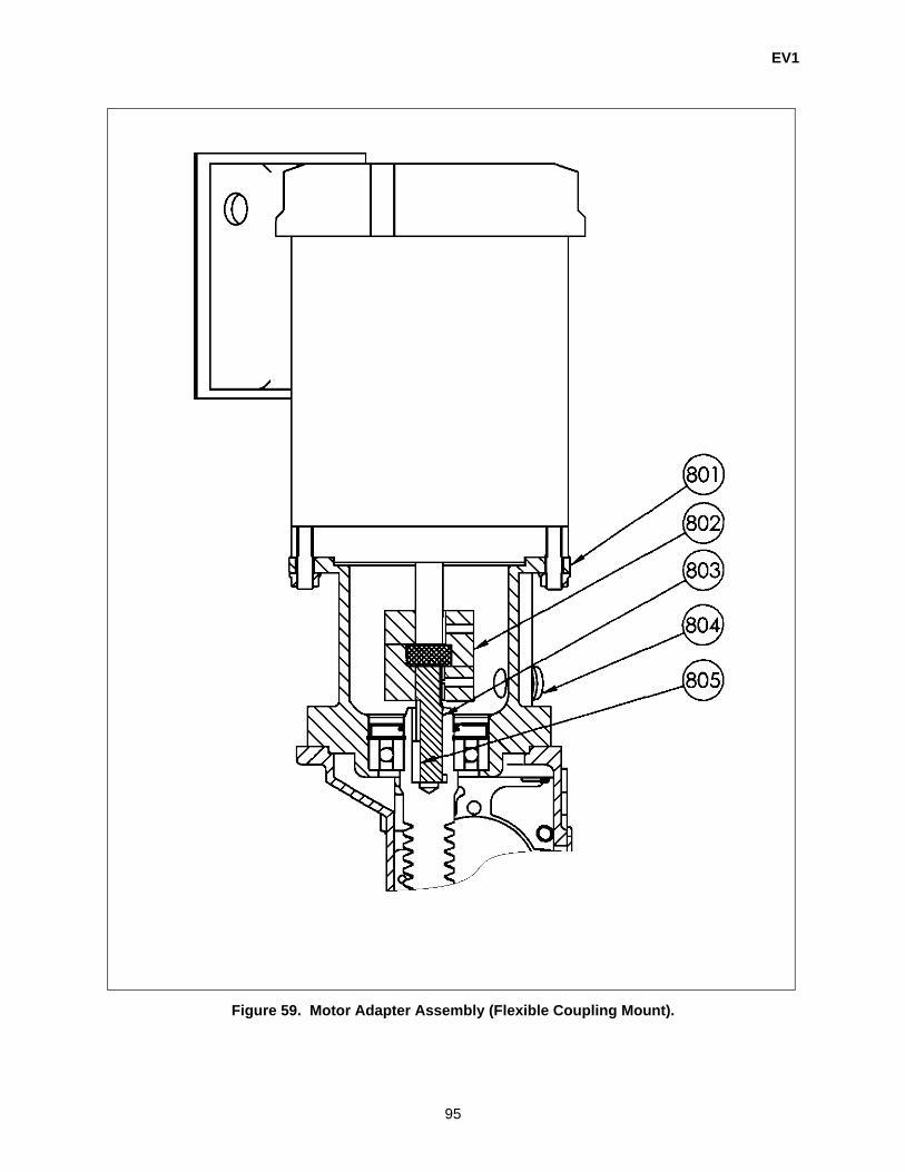
EV1
95
Figure 59. Motor Adapter Assembly (Flexible Coupling Mount).
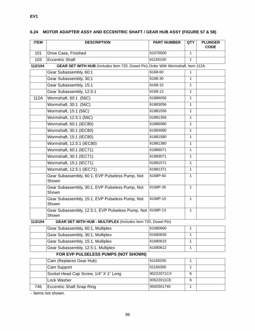
EV1
96
6.24 MOTOR ADAPTER ASSY AND ECCENTRIC SHAFT / GEAR HUB ASSY (FIGURE 57 & 58)
ITEM DESCRIPTION PART NUMBER QTY PLUNGER CODE
101 Drive Case, Finished 61070500 1
103 Eccentric Shaft 61150100 1
112/104 GEAR SET WITH HUB (Includes Item 720, Dowel Pin) Order With Wormshaft, Item 112A
Gear Subassembly, 60:1 6168-60 1
Gear Subassembly, 30;1 6168-30 1
Gear Subassembly, 15:1 6168-15 1
Gear Subassembly, 12.5:1 6168-13 1
112A Wormshaft, 60:1 (56C) 61886056 1
Wormshaft, 30:1 (56C) 61883056 1
Wormshaft, 15:1 (56C) 61881556 1
Wormshaft, 12.5:1 (56C) 61881356 1
Wormshaft, 60:1 (IEC80) 61886080 1
Wormshaft, 30:1 (IEC80) 61883080 1
Wormshaft, 15:1 (IEC80) 61881580 1
Wormshaft, 12.5:1 (IEC80) 61881380 1
Wormshaft, 60:1 (IEC71) 61886071 1
Wormshaft, 30:1 (IEC71) 61883071 1
Wormshaft, 15:1 (IEC71) 61881571 1
Wormshaft, 12.5:1 (IEC71) 61881371 1
Gear Subassembly, 60:1, EVP Pulseless Pump, Not Shown
6168P-60 1
Gear Subassembly, 30;1, EVP Pulseless Pump, Not Shown
6168P-30 1
Gear Subassembly, 15:1, EVP Pulseless Pump, Not Shown
6168P-15 1
Gear Subassembly, 12.5:1, EVP Pulseless Pump, Not Shown
6168P-13 1
113/104 GEAR SET WITH HUB - MULTIPLEX (Includes Item 720, Dowel Pin)
Gear Subassembly, 60:1, Multiplex 61680660 1
Gear Subassembly, 30;1, Multiplex 61680630 1
Gear Subassembly, 15:1, Multiplex 61680615 1
Gear Subassembly, 12.5:1, Multiplex 61680612 1
FOR EVP PULSELESS PUMPS (NOT SHOWN)Cam (Replaces Gear Hub) 61160200 1
Cam Support 61160300 1
Socket Head Cap Screw, 1/4” X 1” Long 90222071CX 6
Lock Washer 93522011CE 6
746 Eccentric Shaft Snap Ring 9592501740 1
- Items not shown.

EV1
97
748 Eccentric Bearing Snap 9593102740 1
756 Eccentric Shaf Ballt 96923011H0 2
766 Needle Bearing 9742517000 2
769 Ball Bearing 9743102000 1
MOTOR ADAPTER ASSEMBLY (Direct Mount)102 Motor Adapter, Direct Mount, NEMA 56C 610856 1
Motor Adapter, Direct Mount, IEC 71 Frame (B5) 610871 1
Motor Adapter, Direct Mount, IEC 80 Frame (B5) 610880 1
111 C-Face Motor Adapter Pinion Gasket 61432100 1
708 Screw, 10” - 24” X 1-1/4” Long 90222151CX 4
715 Stud, 3/8” - 16” X 1-1/2” Long 9092301070 1
717 Flanged Nut 3/8” - 16” 92323011C4 1
740 Input Shaft Seal 9552701000 1
745 Snap Ring Worm Bearing 9582201740 1
747 Snap Ring Worm Shaft 9592702740 1
763 Needle Bearing Standard 9742401000 1
764 Needle Bearing Open 9742414000 1
768 Ball Bearing/MRC 306 9742708000 1
775 Oil Seal 9MT2504000 1
776 Drivecase Plug 9702501000 1
MOTOR ADAPTER ASSEMBLY (Flexible Coupling Mount)(Figure 59)
801 Motor Adapter, Flexible Coupling Mount, NEMA 56C 22536 1
Motor Adapter, Flexible Coupling Mount, IEC 71 Frame (B5)
22540 1
Motor Adapter, Flexible Coupling Mount, IEC 80 Frame (B5)
22543 1
802 Coupling, 5/8 Bore, Lovejoy, NEMA 56C 41000 1
Coupling, 14 mm bore, Lovejoy 41001 1
Coupling, 19 mm bore, Lovejoy 42000 1
803 Worm Adapter Shaft, NEMA 56C 22539 1
Worm Adapter Shaft, IEC 71 22542 1
Worm Adapter Shaft, IEC 80 22544 1
805 Key, 3/16 X 3/16 X 1”, NEMA 56C 2110024406 1
Key, 5 MM X 1”, IEC 71 4042001011 1
Key, 6 MM X 1”, IEC 80 22541 1
804 Plug 9102501560 1
- Retrofit Kit: 56C Direct Mount to 56C Flexible Cou-pling Mount
22575 1
ITEM DESCRIPTION PART NUMBER QTY PLUNGER CODE
- Items not shown.
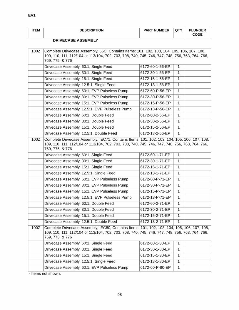
EV1
98
DRIVECASE ASSEMBLY
100Z Complete Drivecase Assembly, 56C, Contains Items: 101, 102, 103, 104, 105, 106, 107, 108, 109, 110, 111, 112/104 or 113/104, 702, 703, 708, 740, 745, 746, 747, 748, 756, 763, 764, 766, 769, 775, & 776Drivecase Assembly, 60:1, Single Feed 6172-60-1-56-EP 1Drivecase Assembly, 30:1, Single Feed 6172-30-1-56-EP 1Drivecase Assembly, 15:1, Single Feed 6172-15-1-56-EP 1Drivecase Assembly, 12.5:1, Single Feed 6172-13-1-56-EP 1Drivecase Assembly, 60:1, EVP Pulseless Pump 6172-60-P-56-EP 1Drivecase Assembly, 30:1, EVP Pulseless Pump 6172-30-P-56-EP 1Drivecase Assembly, 15:1, EVP Pulseless Pump 6172-15-P-56-EP 1Drivecase Assembly, 12.5:1, EVP Pulseless Pump 6172-13-P-56-EP 1Drivecase Assembly, 60:1, Double Feed 6172-60-2-56-EP 1Drivecase Assembly, 30:1, Double Feed 6172-30-2-56-EP 1Drivecase Assembly, 15:1, Double Feed 6172-15-2-56-EP 1Drivecase Assembly, 12.5:1, Double Feed 6172-13-2-56-EP 1
100Z Complete Drivecase Assembly, IEC71, Contains Items: 101, 102, 103, 104, 105, 106, 107, 108, 109, 110, 111, 112/104 or 113/104, 702, 703, 708, 740, 745, 746, 747, 748, 756, 763, 764, 766, 769, 775, & 776Drivecase Assembly, 60:1, Single Feed 6172-60-1-71-EP 1Drivecase Assembly, 30:1, Single Feed 6172-30-1-71-EP 1Drivecase Assembly, 15:1, Single Feed 6172-15-1-71-EP 1Drivecase Assembly, 12.5:1, Single Feed 6172-13-1-71-EP 1Drivecase Assembly, 60:1, EVP Pulseless Pump 6172-60-P-71-EP 1Drivecase Assembly, 30:1, EVP Pulseless Pump 6172-30-P-71-EP 1Drivecase Assembly, 15:1, EVP Pulseless Pump 6172-15-P-71-EP 1Drivecase Assembly, 12.5:1, EVP Pulseless Pump 6172-13-P-71-EP 1Drivecase Assembly, 60:1, Double Feed 6172-60-2-71-EP 1Drivecase Assembly, 30:1, Double Feed 6172-30-2-71-EP 1Drivecase Assembly, 15:1, Double Feed 6172-15-2-71-EP 1Drivecase Assembly, 12.5:1, Double Feed 6172-13-2-71-EP 1
100Z Complete Drivecase Assembly, IEC80, Contains Items: 101, 102, 103, 104, 105, 106, 107, 108, 109, 110, 111, 112/104 or 113/104, 702, 703, 708, 740, 745, 746, 747, 748, 756, 763, 764, 766, 769, 775, & 776Drivecase Assembly, 60:1, Single Feed 6172-60-1-80-EP 1Drivecase Assembly, 30:1, Single Feed 6172-30-1-80-EP 1Drivecase Assembly, 15:1, Single Feed 6172-15-1-80-EP 1Drivecase Assembly, 12.5:1, Single Feed 6172-13-1-80-EP 1Drivecase Assembly, 60:1, EVP Pulseless Pump 6172-60-P-80-EP 1
ITEM DESCRIPTION PART NUMBER QTY PLUNGER CODE
- Items not shown.

EV1
99
Drivecase Assembly, 30:1, EVP Pulseless Pump 6172-30-P-80-EP 1Drivecase Assembly, 15:1, EVP Pulseless Pump 6172-15-P-80-EP 1Drivecase Assembly, 12.5:1, EVP Pulseless Pump 6172-13-P-80-EP 1Drivecase Assembly, 60:1, Double Feed 6172-60-2-80-EP 1Drivecase Assembly, 30:1, Double Feed 6172-30-2-80-EP 1Drivecase Assembly, 15:1, Double Feed 6172-15-2-80-EP 1Drivecase Assembly, 12.5:1, Double Feed 6172-13-2-80-EP 1
ITEM DESCRIPTION PART NUMBER QTY PLUNGER CODE
- Items not shown.

EV1
100
Figure 60. Covers, Drivecase & Multiplex Pump Accessories.

EV1
101
6.25 COVERS, DRIVECASE & MULTIPLEX PUMP ACCESSORIES (FIGURE 60)
ITEM DESCRIPTION PART NUMBER QTY PLUNGER CODE
101 Drive Case 61070500 1
105 End Cover (1 Feed) 61190100 1
106 Eccentric Shaft Retainer Plate Cover 61190200 2
107 Stroke Adjuster Cover (1 Feed) 61190300 1
108 Stroke Adjuster Gasket Cover 61430100 2
109 Eccentric Shaft Retainer Plate Shim 61430200 2
110 End Cover Gasket (1Feed) 61430300 1
641 Base Top Mount 61063500 1
702 Screw, 10” - 24” X 3/8” Long 90122061C4 8
703 Screw, 3/8” - 16” X 1/2” Long 90223021CX 8
715 Stud, 3/8” - 16” X 1-1/2” Long 9092301070 4
717 Flanged Nut 3/8” X 16” 92323011C4 4
725 Key 1/8” X 13/16” Long 9452109020 1
753 Sight Plug 9702362000 2
760 Breather 6075A-06 1
761 Pipe Plug 3/8” 970230402E 4
777 Cap Plug 9102501560 1
779 Relief Valve Cap Gasket 9562501000 1
790 C-Face Motor Gasket 61430400 1
- Nipple, 3/8 NPT X 2 970226402H 1
- Pipe Cap 970226302H 1
- 3/8 NPT Steel Elbow 970226202H 1
MULTIPLEX PUMP ACCESSORIES
643 Multiplex Side Rail 2 Unit 61061902 2
Multiplex Side Rail 3 Unit 61061903 2
Multiplex Side Rail 4 Unit 61061904 2
Multiplex Side Rail 5 Unit 61061905 2
644 Base Motor Mount Multiplex 61062000 1
646 Cross Member - End Cap Tall 61062600 2 + 3 Unit = 14 + 5 Unit = 2
647* Coupling Guard - Multiplex 61870700 2 Unit = 13 Unit = 24 Unit = 35 Unit = 4
648 Cross Member - End Cap Short 61062300 1
650 Hex Bolt, 3/8” - 16” x 3/4” Long 901230102P 4 Per Drive-case / 6 Per
Base
651 Hex Nut, 3/8” X 16” 91923021CE 6 Per Base
- Items not shown.

EV1
102
652 Lockwasher Spring, 3/8” 93523071CE 4 Per Drive-case / 6 Per
Base
653 Flat Washer, 3/8” 934230502E 10 Per Base
120 Multiplex - Spacer Shaft 61150900 Same as 647
725 Key, 1/8” X 13/16” Long 9452109020 Same as 647 X 2
727 Multiplex - Spacer Shaft Key 9452215020 Same as 647
764 needle Bearing Open 9742414000 Same as 647
772 Multiplex - Spacer Coupling 0.50” 9M42501100 Same as 647
775 Oil Seal 9MT2504000 Same as 647
800 Oil, Size A (Mobil SHC 524) 20040 4 QTS 03D, 04D, 06D
800 Oil, Size B & C (Mobil SHC 629) 4070324030 4 QTS 10D, 14D, 20D, 28D,
38D- Foot Mount Motor Coupling 0.62” 9M42501000 Same as 647
- Spacer Shaft 61150500 Same as 647
- Screw, 5/16” - 18” X 2” Long 90123391CE 4
- Hex Jam Nut, 5/16” - 18” 91923011CE 4
- Washer 934230211E 8
- Lockwasher 93523021CE 4
ITEM DESCRIPTION PART NUMBER QTY PLUNGER CODE
- Items not shown.

EV1 PUMP FACTSPAGE 1 OF 2
Effective 10/08Supersedes ALL
EV1Minimum Temperature - 20°F (Below 40°F use synthetic oil)Maximum Temperature Metallic 250°F (Above 100°F use synthetic oil)
Non-Metallic 150°F (Above 100°F see Tech Tip TU096-09)
Size Plunger Diameter STD ModifiedMaximum Suction Pressure A 3/16", 1/4", 3/8" 150 PSIG N/A
B 5/8", 7/8", 1-1/4" 150 PSIG 400 PSIGC 1-3/4", 2-3/8" 50 PSIG 200 PSIG
Higher suction pressures available. Consult Factory.For maximum discharge pressure, consult Durameter sizing program or selection guide .
Lubrication Capacity 3.3 quartsSize A - 3/16, 1/4, 3/8 Plunger Dia. - Mobil SHC 524Size B & C - 5/8 to 2-3/8 Plunger Dia. - Mobil SHC 629
Flow Range .08 GPH @ 3500 PSI to 110 GPH @ 150 PSI SIMPLEX (220 GPH DUPLEX)
Stroke Length .75"
Shipping Weight One (1) Feed 100-110 lbs. with 1/3 HP Motor (varies with plunger/liquid end size)Two (2) Feeds 115-125 lbs. with 1/3 HP Motor (varies with plunger/liquid end size)
Pump Dimensions Size Plunger Size Check Connection SizeA 3/16",1/4",3/8" 1/4" NPT (M) - Metallic Head
1/2" NPT (M) - Plastic HeadB 5/8", 7/8", 1-1/4" 3/8" NPT (F)C 1-3/4", 2-3/8" 3/8" NPT (F)
Motor Frame NEMA 56C TEFC, IEC 71 OR IEC 80, Chemical Duty or Explosion Proof
Materials of Construction
Drivecase Cast Iron - Powder Coated (Polyester TGIC)Baseplate Carbon Steel - Powder Coated (Polyester TGIC)
Wetted Material 316SS Alloy 20 Hast1 C PVC Kynar Slurry CVLiquid Head 316SS Alloy 20 Hast C PVC Kynar 316SSCheck Valve Ball 316SS Alloy 20 Hast C Al-Cer Al-Cer TCCheck Valve Cap 316SS Alloy 20 Hast C PVC Kynar 316SSBall Guide 316SS Alloy 20 Hast C PVC Kynar 316SSCheck Valve Seat Size A 316SS Alloy 20 Hast C PTFE PTFE N/ACheck Valve Seat Size B, C 316SS Alloy 20 Hast C PVC Kynar C-2/TCDiaphragm & Check Valve Gasket PTFE PTFE PTFE PTFE PTFE PTFE1 Registered trademark for Haynes International
103

EV1 PUMP FACTSPAGE 2 OF 2
Effective 10/08Supersedes ALL
Application Limitations:
NPSHR is 10 PSIA as calculated using NPSH worksheet or NPSH Tab in Durameter Sizing Program.
NPSH calculations are for Newtonian fluids only. Consult Factory for non-Newtonian fluids.
Type: Hydraulically balanced single or double diaphragm.Single or double ball check, lost motion drive.
Uses: Viscous Service (NPSH Calculation Required) Odorous / Toxic ServiceHazardous / Carcinogen Service Accurate Chemical Injection
Typical Markets: Chemical Process RefineryPulp and Paper Food and BeveragePharmaceutical Waste Water TreatmentPower Generation MiningWater Treatment ManufacturingOil Exploration / Transmission / Recovery Gas Exploration / Transmission / Recovery
Options: Slurry or Double Ball Check ValvesHorizontal Motor Mount
EVP™ Pulse-less, Linear Flow Metering Multiplexing (up to12 feeds with 1 motor)
Special Metallics and Non-Metallics Two (2) feeds from one (1) drivecase
Features: Cartridge Design Parts Interchangeability AccuracyDependability Ease of Maintenance C-Face Motor MountDurability Mounting Flexibility No Process Side Contour PlateDual Feed Capability Cost Effective Many Options Available
EV1
Diaphragm Rupture Leak Detection SystemsElectronic Stroke Control in Nema 4 or 7
104


THIS PAGE INTENTIONALLY BLANK

Milton Roy201 Ivyland RoadIvyland, PA 18974-0577Phone: (215) 441-0800FAX: 215-441-8620www.miltonroy.comE-mail: [email protected]