Installation, Operation, and Maintenance Information · Installation, Operation, and Maintenance...
16
Installation, Operation, and Maintenance Information Air-Cooled Condensers Table of Contents General Safety Information...................................................................................................................................................................... 2 Inspection ................................................................................................................................................................................................. 2 Installation .......................................................................................................................................................................................... 2 – 6 Rigging and Assembly ........................................................................................................................................................................... 2 Unit Location .......................................................................................................................................................................................... 3 Piping Recommendations ................................................................................................................................................................ 4 – 6 Discharge Lines ..................................................................................................................................................................... 4 – 5 Liquid Lines .................................................................................................................................................................................. 5 Multiple Condensers .................................................................................................................................................................... 6 Routing of Piping .......................................................................................................................................................................... 6 Head Pressure Control Options and Charge Calculations ........................................................................................................... 6 – 11 Flooded Condenser Head Pressure Control Option ......................................................................................................................... 6 – 7 Refrigeration Charge Calculation ..................................................................................................................................................... 7 – 8 Splitting Controls .................................................................................................................................................................................... 8 Fan Cycling Control Option ............................................................................................................................................................ 9 – 10 Fan Speed Control Option ................................................................................................................................................................... 10 Flooded Condenser Option with Fan Cycling ............................................................................................................................... 10 – 11 Wiring Diagrams ............................................................................................................................................................................. 11 – 12 Start-Up Procedure ................................................................................................................................................................................ 12 Maintenance............................................................................................................................................................................................ 13 Replacement Parts ................................................................................................................................................................................. 14 Service Record ....................................................................................................................................................................................... 15 www.htpgusa.com Part # 08499024
Transcript of Installation, Operation, and Maintenance Information · Installation, Operation, and Maintenance...
Installation, Operation, and Maintenance Information
Air-Cooled Condensers
Table of Contents General Safety Information ...................................................................................................................................................................... 2 Inspection ................................................................................................................................................................................................. 2 Installation .......................................................................................................................................................................................... 2 – 6
Rigging and Assembly ........................................................................................................................................................................... 2 Unit Location .......................................................................................................................................................................................... 3 Piping Recommendations ................................................................................................................................................................ 4 – 6
Discharge Lines ..................................................................................................................................................................... 4 – 5 Liquid Lines .................................................................................................................................................................................. 5 Multiple Condensers .................................................................................................................................................................... 6 Routing of Piping .......................................................................................................................................................................... 6
Head Pressure Control Options and Charge Calculations ........................................................................................................... 6 – 11Flooded Condenser Head Pressure Control Option ......................................................................................................................... 6 – 7 Refrigeration Charge Calculation ..................................................................................................................................................... 7 – 8 Splitting Controls .................................................................................................................................................................................... 8 Fan Cycling Control Option ............................................................................................................................................................ 9 – 10Fan Speed Control Option ................................................................................................................................................................... 10 Flooded Condenser Option with Fan Cycling ............................................................................................................................... 10 – 11
Wiring Diagrams ............................................................................................................................................................................. 11 – 12Start-Up Procedure ................................................................................................................................................................................ 12 Maintenance ............................................................................................................................................................................................ 13 Replacement Parts ................................................................................................................................................................................. 14 Service Record ....................................................................................................................................................................................... 15
www.htpgusa.com
Part # 08499024
2
GENERAL SAFETY INFORMATION 1. Installation and maintenance are to be performed only by qualified personnel who are familiar with this type of equipment. 2. Make sure that all field wiring conforms to the requirements of the equipment and all applicable national and local codes. 3. Avoid contact with sharp edges and coil surfaces. They are potential injury hazards. 4. All power sources must be disconnected prior to any servicing or maintenance of this unit. After disconnecting power, allow 5 minutes for capacitor discharge before servicing motors. 5. Refrigerant recovery devices must be used during installation and service of this equipment. It is illegal for some refrigerants to be released into the atmosphere.
INSPECTION
Check all items against the bill of lading to make sure all crates or cartons have been received. If there is any damage, report it immediately to the carrier and file a claim. Make sure the voltage on the unit nameplate agrees with the power supply available.
INSTALLATION
Rigging and Assembly
Leave the units in the carton or on the skid until they are as close as possible to the installation location. Never lift any of the units
by the headers, return bends, or electrical boxes. All condensers are provided with lifting points located in the top of each leg
channel and bottom of each leg, above and below the side panel. The actual method of rigging depends on the equipment
available, the size of the unit, and where the unit is to be located. It is up to the installer to decide the best way to handle each
unit. A spreader bar should always be used and should be at least as long as the distance between the lifting points.
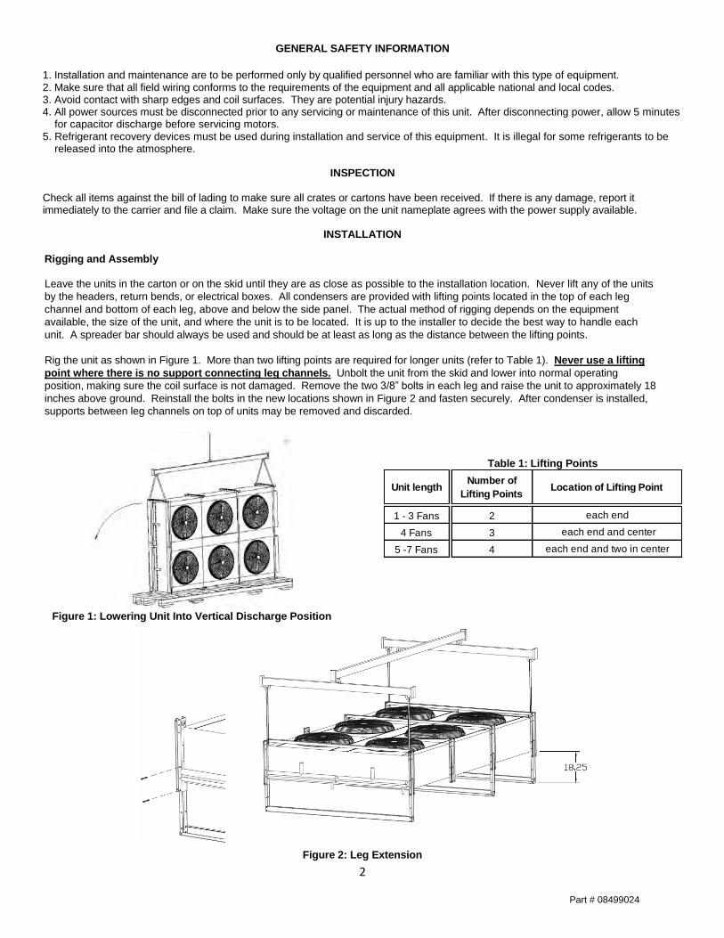
Rig the unit as shown in Figure 1. More than two lifting points are required for longer units (refer to Table 1). Never use a lifting
point where there is no support connecting leg channels. Unbolt the unit from the skid and lower into normal operating
position, making sure the coil surface is not damaged. Remove the two 3/8” bolts in each leg and raise the unit to approximately 18
inches above ground. Reinstall the bolts in the new locations shown in Figure 2 and fasten securely. After condenser is installed,
supports between leg channels on top of units may be removed and discarded.
Figure 1: Lowering Unit Into Vertical Discharge Position
Table 1: Lifting Points
Figure 2: Leg Extension
Unit lengthNumber of
Lifting PointsLocation of Lifting Point
1 - 3 Fans 2 each end
4 Fans 3 each end and center
5 -7 Fans 4 each end and two in center
Part # 08499024
3
Unit Location
General
These units are designed for outdoor applications. All units must be installed level for proper drainage of liquid refrigerant and
oil. When units are installed on a roof, they must be mounted on support beams that span load walls. Ground mounted units
should be installed on concrete pads. When selecting a location for an air-cooled condenser, be sure to allocate space for
maintenance and service work.
Space Requirements
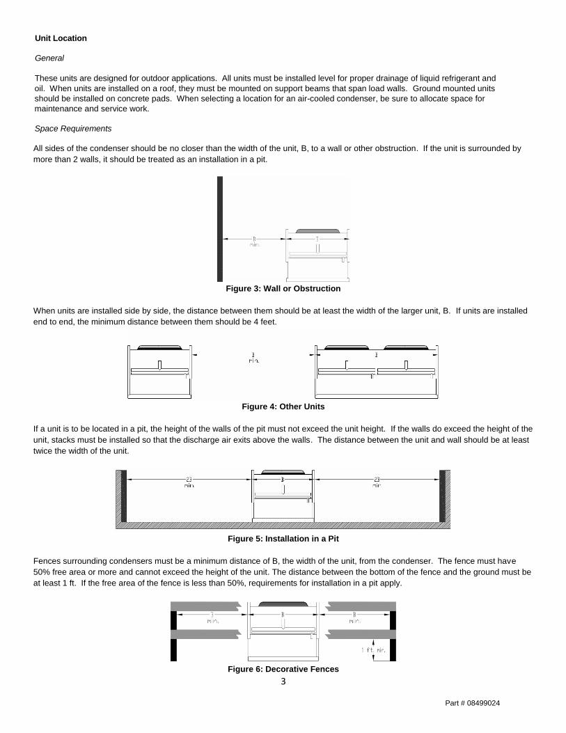
All sides of the condenser should be no closer than the width of the unit, B, to a wall or other obstruction. If the unit is surrounded by
more than 2 walls, it should be treated as an installation in a pit.
Figure 3: Wall or Obstruction
When units are installed side by side, the distance between them should be at least the width of the larger unit, B. If units are installed
end to end, the minimum distance between them should be 4 feet.
Figure 4: Other Units
If a unit is to be located in a pit, the height of the walls of the pit must not exceed the unit height. If the walls do exceed the height of the
unit, stacks must be installed so that the discharge air exits above the walls. The distance between the unit and wall should be at least
twice the width of the unit.
Figure 5: Installation in a Pit
Fences surrounding condensers must be a minimum distance of B, the width of the unit, from the condenser. The fence must have
50% free area or more and cannot exceed the height of the unit. The distance between the bottom of the fence and the ground must be
at least 1 ft. If the free area of the fence is less than 50%, requirements for installation in a pit apply.
Figure 6: Decorative Fences
Part # 08499024
4
PIPING RECOMMENDATIONS
The following are general guidelines for routing and sizing lines to air-cooled condensers. For further information please
consult the ASHRAE Handbook or other accepted piping handbooks.
Discharge Lines
Consider the following three issues when designing and sizing discharge lines.
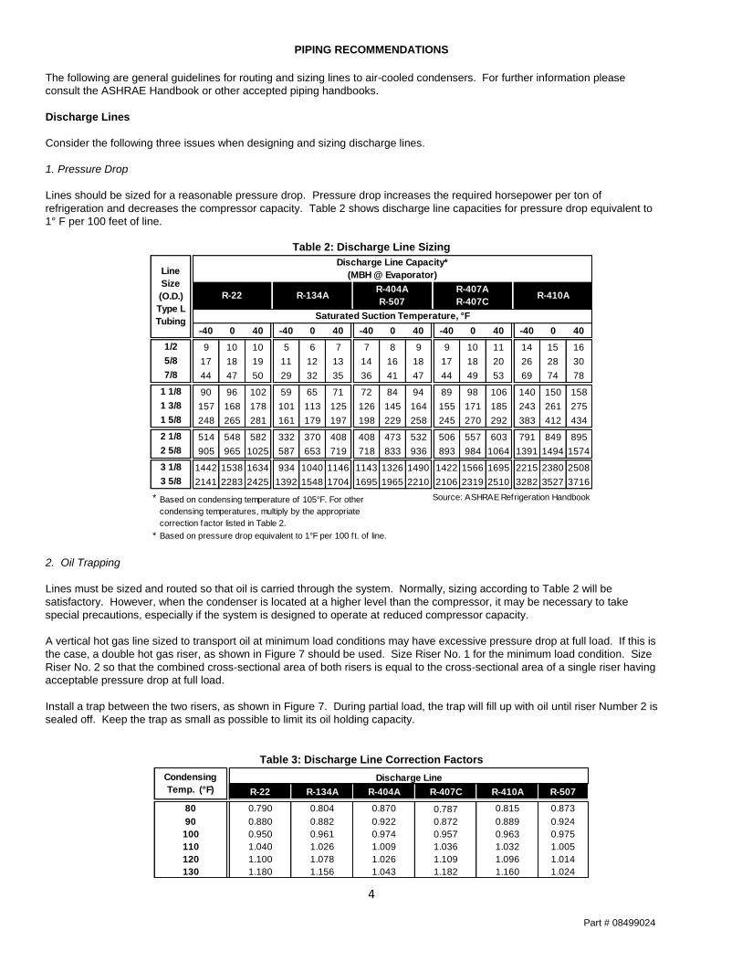
1. Pressure Drop
Lines should be sized for a reasonable pressure drop. Pressure drop increases the required horsepower per ton of
refrigeration and decreases the compressor capacity. Table 2 shows discharge line capacities for pressure drop equivalent to
1° F per 100 feet of line.
Table 2: Discharge Line Sizing
2. Oil Trapping
Lines must be sized and routed so that oil is carried through the system. Normally, sizing according to Table 2 will be
satisfactory. However, when the condenser is located at a higher level than the compressor, it may be necessary to take
special precautions, especially if the system is designed to operate at reduced compressor capacity.
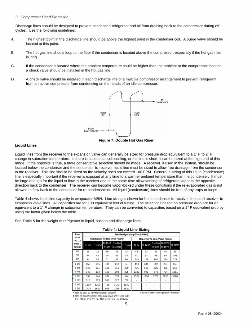
A vertical hot gas line sized to transport oil at minimum load conditions may have excessive pressure drop at full load. If this is
the case, a double hot gas riser, as shown in Figure 7 should be used. Size Riser No. 1 for the minimum load condition. Size
Riser No. 2 so that the combined cross-sectional area of both risers is equal to the cross-sectional area of a single riser having
acceptable pressure drop at full load.
Install a trap between the two risers, as shown in Figure 7. During partial load, the trap will fill up with oil until riser Number 2 is
sealed off. Keep the trap as small as possible to limit its oil holding capacity.
Table 3: Discharge Line Correction Factors
-40 0 40 -40 0 40 -40 0 40 -40 0 40 -40 0 40
9 10 10 5 6 7 7 8 9 9 10 11 14 15 16
17 18 19 11 12 13 14 16 18 17 18 20 26 28 30
44 47 50 29 32 35 36 41 47 44 49 53 69 74 78
90 96 102 59 65 71 72 84 94 89 98 106 140 150 158
157 168 178 101 113 125 126 145 164 155 171 185 243 261 275
248 265 281 161 179 197 198 229 258 245 270 292 383 412 434
514 548 582 332 370 408 408 473 532 506 557 603 791 849 895
905 965 1025 587 653 719 718 833 936 893 984 1064 1391 1494 1574
1442 1538 1634 934 1040 1146 1143 1326 1490 1422 1566 1695 2215 2380 2508
2141 2283 2425 1392 1548 1704 1695 1965 2210 2106 2319 2510 3282 3527 3716
* Source: ASHRAE Refrigeration Handbook
* Based on pressure drop equivalent to 1°F per 100 ft. of line.
Based on condensing temperature of 105°F. For other
condensing temperatures, multiply by the appropriate
correction factor listed in Table 2.
1 5/8
1 3/8
1 1/8
7/8
5/8
1/2
R-134A
3 1/8
3 5/8
R-407A
R-407CR-22
Saturated Suction Temperature, °F
R-404A
R-507R-410A
2 5/8
2 1/8
Line
Size
(O.D.)
Type L
Tubing
Discharge Line Capacity*
(MBH @ Evaporator)
R-22 R-134A R-404A R-407C R-410A R-507
80 0.790 0.804 0.870 0.787 0.815 0.873
90 0.880 0.882 0.922 0.872 0.889 0.924
100 0.950 0.961 0.974 0.957 0.963 0.975
110 1.040 1.026 1.009 1.036 1.032 1.005
120 1.100 1.078 1.026 1.109 1.096 1.014
130 1.180 1.156 1.043 1.182 1.160 1.024
Discharge LineCondensing
Temp. (°F)
Part # 08499024
5
3. Compressor Head Protection
Discharge lines should be designed to prevent condensed refrigerant and oil from draining back to the compressor during off
cycles. Use the following guidelines:
A. The highest point in the discharge line should be above the highest point in the condenser coil. A purge valve should be
located at this point.
B. The hot gas line should loop to the floor if the condenser is located above the compressor, especially if the hot gas riser
is long.
C. If the condenser is located where the ambient temperature could be higher than the ambient at the compressor location,
a check valve should be installed in the hot gas line.
D. A check valve should be installed in each discharge line of a multiple compressor arrangement to prevent refrigerant
from an active compressor from condensing on the heads of an idle compressor.
Figure 7: Double Hot Gas Riser
Liquid Lines
Liquid lines from the receiver to the expansion valve can generally be sized for pressure drop equivalent to a 1° F to 2° F
change in saturation temperature. If there is substantial sub cooling, or the line is short, it can be sized at the high end of this
range. If the opposite is true, a more conservative selection should be made. A receiver, if used in the system, should be
located below the condenser and the condenser-to-receiver liquid line must be sized to allow free drainage from the condenser
to the receiver. This line should be sized so the velocity does not exceed 100 FPM. Generous sizing of this liquid (condensate)
line is especially important if the receiver is exposed at any time to a warmer ambient temperature than the condenser. It must
be large enough for the liquid to flow to the receiver and at the same time allow venting of refrigerant vapor in the opposite
direction back to the condenser. The receiver can become vapor-locked under these conditions if the re-evaporated gas is not
allowed to flow back to the condenser for re-condensation. All liquid (condensate) lines should be free of any traps or loops.
Table 4 shows liquid line capacity in evaporator MBH. Line sizing is shown for both condenser-to-receiver lines and receiver-to-
expansion valve lines. All capacities are for 100 equivalent feet of tubing. The selections based on pressure drop are for an
equivalent to a 1° F change in saturation temperature. They can be converted to capacities based on a 2° F equivalent drop by
using the factor given below the table.
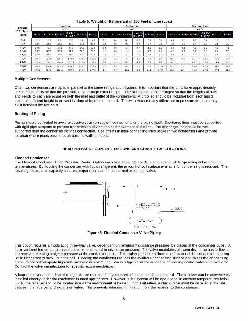
See Table 5 for the weight of refrigerant in liquid, suction and discharge lines.
Table 4: Liquid Line Sizing
R-404A R-407A R-404A R-407A
R-507 R-407C R-507 R-407C
28 26 16 25 24 43 33 31 46 55
44 41 25 41 38 80 63 58 85 103
94 85 52 83 80 218 168 152 224 271
158 145 88 142 137 444 341 307 224 550
242 221 135 216 209 776 600 535 455 956
342 313 190 306 295 1230 943 846 794 1511
595 544 331 533 514 2556 1956 1752 1256 3128
918 839 510 822 792 - - - - -
1310 1200 728 1172 1130 - - - - -
1774 1620 985 1586 1529 - - - - -
* Based on 100 FPM refrigerant velocity. Source: ASHRAE Refrigeration Handbook
†
R-410A R-22 R-134A R-410A
Condenser To Receiver Piping* Receiver To Exp. Valve Piping†
Net Refrigerating Effect (MBH)
Based on refrigerant pressure drop of 1°F per 100
feet of line. For 2°F per 100 feet of line, multiply by
Line
Size
(O.D.)
Type L
Tubing
1/2
5/8
7/8
1 1/8
1 3/8
1 5/8
2 1/8
2 5/8
3 1/8
3 5/8
R-22 R-134A
Part # 08499024
6
Table 5: Weight of Refrigerant in 100 Feet of Line (Lbs.)
Multiple Condensers
Often two condensers are piped in parallel to the same refrigeration system. It is important that the units have approximately
the same capacity so that the pressure drop through each is equal. The piping should be arranged so that the lengths of runs
and bends to each are equal on both the inlet and outlet of the condensers. A drop leg should be included from each liquid
outlet of sufficient height to prevent backup of liquid into one coil. This will overcome any difference in pressure drop that may
exist between the two coils.
Routing of Piping
Piping should be routed to avoid excessive strain on system components or the piping itself. Discharge lines must be supported
with rigid pipe supports to prevent transmission of vibration and movement of the line. The discharge line should be well
supported near the condenser hot gas connection. Use offsets in inter-connecting lines between two condensers and provide
isolation where pipes pass through building walls or floors.
HEAD PRESSURE CONTROL OPTIONS AND CHARGE CALCULATIONS
Flooded Condenser
The Flooded Condenser Head Pressure Control Option maintains adequate condensing pressure while operating in low ambient temperatures. By flooding the condenser with liquid refrigerant, the amount of coil surface available for condensing is reduced. The resulting reduction in capacity ensures proper operation of the thermal expansion valve.
Figure 8: Flooded Condenser Valve Piping
This option requires a modulating three-way valve, dependent on refrigerant discharge pressure, be placed at the condenser outlet. A fall in ambient temperature causes a corresponding fall in discharge pressure. The valve modulates allowing discharge gas to flow to the receiver, creating a higher pressure at the condenser outlet. This higher pressure reduces the flow out of the condenser, causing liquid refrigerant to back up in the coil. Flooding the condenser reduces the available condensing surface and raises the condensing pressure so that adequate high-side pressure is maintained. Various types and combinations of flooding control valves are available. Contact the valve manufacturer for specific recommendations. A larger receiver and additional refrigerant are required for systems with flooded condenser control. The receiver can be conveniently installed directly under the condenser in most applications. However, if the system will be operational in ambient temperatures below 55° F, the receiver should be located in a warm environment or heated. In this situation, a check valve must be installed in the line between the receiver and expansion valve. This prevents refrigerant migration from the receiver to the condenser.
Part # 08499024
7
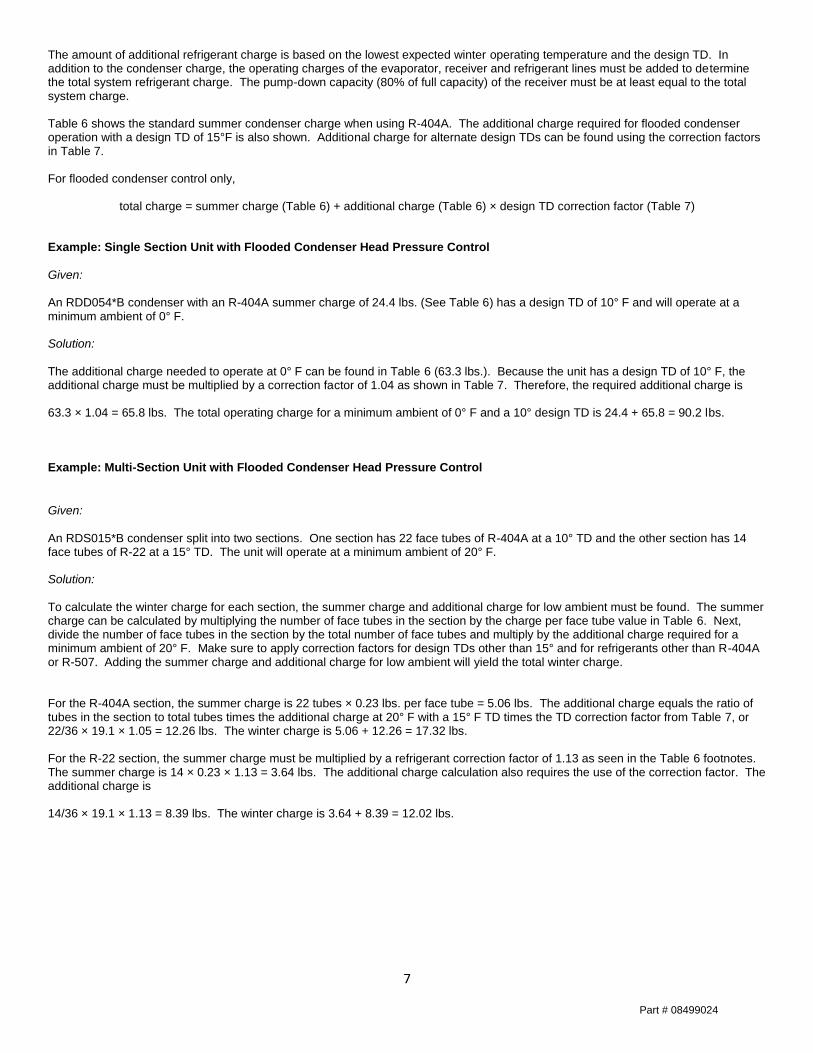
The amount of additional refrigerant charge is based on the lowest expected winter operating temperature and the design TD. In addition to the condenser charge, the operating charges of the evaporator, receiver and refrigerant lines must be added to determine the total system refrigerant charge. The pump-down capacity (80% of full capacity) of the receiver must be at least equal to the total system charge. Table 6 shows the standard summer condenser charge when using R-404A. The additional charge required for flooded condenser operation with a design TD of 15°F is also shown. Additional charge for alternate design TDs can be found using the correction factors in Table 7. For flooded condenser control only,
total charge = summer charge (Table 6) + additional charge (Table 6) × design TD correction factor (Table 7) Example: Single Section Unit with Flooded Condenser Head Pressure Control
Given: An RDD054*B condenser with an R-404A summer charge of 24.4 lbs. (See Table 6) has a design TD of 10° F and will operate at a minimum ambient of 0° F. Solution: The additional charge needed to operate at 0° F can be found in Table 6 (63.3 lbs.). Because the unit has a design TD of 10° F, the additional charge must be multiplied by a correction factor of 1.04 as shown in Table 7. Therefore, the required additional charge is 63.3 × 1.04 = 65.8 lbs. The total operating charge for a minimum ambient of 0° F and a 10° design TD is 24.4 + 65.8 = 90.2 lbs. Example: Multi-Section Unit with Flooded Condenser Head Pressure Control
Given: An RDS015*B condenser split into two sections. One section has 22 face tubes of R-404A at a 10° TD and the other section has 14 face tubes of R-22 at a 15° TD. The unit will operate at a minimum ambient of 20° F. Solution: To calculate the winter charge for each section, the summer charge and additional charge for low ambient must be found. The summer charge can be calculated by multiplying the number of face tubes in the section by the charge per face tube value in Table 6. Next, divide the number of face tubes in the section by the total number of face tubes and multiply by the additional charge required for a minimum ambient of 20° F. Make sure to apply correction factors for design TDs other than 15° and for refrigerants other than R-404A or R-507. Adding the summer charge and additional charge for low ambient will yield the total winter charge. For the R-404A section, the summer charge is 22 tubes × 0.23 lbs. per face tube = 5.06 lbs. The additional charge equals the ratio of tubes in the section to total tubes times the additional charge at 20° F with a 15° F TD times the TD correction factor from Table 7, or 22/36 × 19.1 × 1.05 = 12.26 lbs. The winter charge is 5.06 + 12.26 = 17.32 lbs. For the R-22 section, the summer charge must be multiplied by a refrigerant correction factor of 1.13 as seen in the Table 6 footnotes. The summer charge is 14 × 0.23 × 1.13 = 3.64 lbs. The additional charge calculation also requires the use of the correction factor. The additional charge is 14/36 × 19.1 × 1.13 = 8.39 lbs. The winter charge is 3.64 + 8.39 = 12.02 lbs.
Part # 08499024
8
Table 6: Additional Refrigerant Charge for Flooded Condensers
Table 7: Low Ambient Design TD Correction Factors
Splitting Controls
Condenser splitting controls assist in maintaining head pressure while minimizing the amount of refrigerant required for the system. A single condenser is split into two parallel circuits, allowing half of the condenser to be removed from the refrigerant circuit during low ambient operation. This is achieved by installing a three way solenoid valve at the condenser inlet, regulated by either a temperature sensing controller or pressure switch. Additional controls are required for the Splitting Control Option on double wide units to shut off the fan motors on the unused portion of the coil.
1140 850 550 VSEC 60 40 20 0 -20
009 010, 012 008 014 0.11 4.1 5.9 8.3 9.6 10.5 11.2
013 013, 014 010 017 0.17 6.1 9.1 12.7 14.5 15.8 16.9
014 018 011 021 0.23 8.1 12.0 16.0 18.3 20.7 21.8
015, 019 016, 023 017 026 0.23 8.1 11.8 16.6 19.1 20.9 22.4
020, 028 017, 027 020 029 0.34 12.2 18.2 25.3 29.0 31.7 33.8
036 031 022 038 0.45 16.2 24.0 31.9 36.6 41.3 43.7
041 039 028 044 0.51 18.3 27.3 38.0 43.5 47.5 50.7
050 049 032 051 0.68 24.3 36.0 47.9 54.9 62.0 65.5
053 051 037 054 0.68 24.4 36.5 50.7 58.1 63.3 67.6
065 058 043 066 0.90 32.4 48.0 63.8 73.2 82.7 87.4
077 069 050 080 1.41 50.9 80.3 111.0 126.9 138.2 147.4
081 077 052 083 1.93 69.6 93.2 135.8 159.1 175.8 189.1
096 092 062 098 2.32 83.5 111.8 163.0 190.9 211.0 226.9
124 114 071 127 2.71 97.4 130.5 190.1 222.7 246.1 264.7
047 048 043 034 0.23 16.2 23.7 33.2 38.3 41.9 44.8
054 052 040 048 0.34 24.4 36.5 50.7 58.1 63.3 67.6
066 059 044 055 0.45 32.4 48.0 63.8 73.2 82.7 87.4
080 082 076 056 0.51 36.6 96.3 133.2 152.3 165.9 176.9
099 101 091 064 0.68 48.6 72.0 95.8 109.7 124.0 131.0
108 109 103 074 0.68 48.8 72.9 101.3 116.1 126.7 135.2
132 134 118 086 0.90 64.8 96.0 127.7 146.3 165.4 174.7
154 156 138 100 1.41 101.7 160.6 222.0 253.8 276.5 294.9
162 163 155 104 1.93 139.2 186.4 271.6 318.2 351.6 378.2
193 195 183 124 2.32 167.0 223.7 325.9 381.8 421.9 453.8
247 250 228 142 2.71 194.8 261.0 380.2 445.5 492.2 529.5
* For R-22, multiply by 1.13.* For R-134A, multiply by 1.15.
* For R-410A, multiply by 1.02.
* For R-407A or R-407C, multiply by 1.09.
72
† Based on 90° F condensing temperature.
SINGLE FAN-WIDTH UNITS MINIMUM AMBIENT TEMPERATURE (° F)
36
DOUBLE FAN-WIDTH UNITS
Unit Size
Numbe
r of
Face
Tubes
R-404A & R-507*
Additional Charge Required for Low Ambient
Temperatures, 15° F Design TD†
Charge Per
Face Tube
(Lbs.)
Total Summer
Charge (Lbs.)
Motor Speed (RPM)
30 25 20 15 10
0.00 0.40 0.76 1.00 1.24
0.73 0.84 0.92 1.00 1.09
0.86 0.92 0.95 1.00 1.05
0.91 0.94 0.97 1.00 1.04
0.93 0.96 0.98 1.00 1.02
20
0
-20
60
40
Minimum Ambient
Temperature (°F)
Design T.D.
Part # 08499024
9
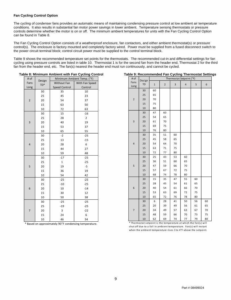
Fan Cycling Control Option
The cycling of condenser fans provides an automatic means of maintaining condensing pressure control at low ambient air temperature conditions. It also results in substantial fan motor power savings in lower ambient. Temperature sensing thermostats or pressure controls determine whether the motor is on or off. The minimum ambient temperatures for units with the Fan Cycling Control Option can be found in Table 8. The Fan Cycling Control Option consists of a weatherproof enclosure, fan contactors, and either ambient thermostat(s) or pressure control(s). The enclosure is factory mounted and completely factory wired. Power must be supplied from a fused disconnect switch to the power circuit terminal block; control circuit power must be supplied to the control terminal block. Table 9 shows the recommended temperature set points for the thermostats. The recommended cut-in and differential settings for fan cycling using pressure controls are listed in table 10. Thermostat 1 is for the second fan from the header end, Thermostat 2 for the third fan from the header end, etc. The fan(s) nearest the header end must run continuously, and cannot be cycled.
Table 8: Minimum Ambient with Fan Cycling Control
Table 9: Recommended Fan Cycling Thermostat Settings
Without Fan
Speed Control
With Fan Speed
Control
30 35 10
25 45 23
20 54 37
15 63 50
10 72 63
30 15 -16
25 28 2
20 40 19
15 53 37
10 65 55
30 -2 -25
25 13 -15
20 28 6
15 44 27
10 59 48
30 -17 -25
25 1 -25
20 19 -5
15 36 19
10 54 42
30 -25 -25
25 -10 -25
20 10 -14
15 30 12
10 50 38
30 -25 -25
25 -19 -25
20 3 -22
15 24 6
10 46 34
* Based on approximately 90°F condensing temperature.
4
5
6
7
Minimum Ambient Temp. (°F)Design
TD*
# of
Fans
Long
2
3
1 2 3 4 5 6
30 60
25 65
20 70
15 75
10 80
30 47 60
25 54 65
20 61 70
15 69 75
10 76 80
30 35 51 60
25 45 58 65
20 54 64 70
15 63 71 75
10 72 77 80
30 25 43 53 60
25 36 51 60 65
20 47 59 66 70
15 57 67 72 75
10 68 74 78 80
30 15 35 47 55 60
25 28 45 54 61 65
20 40 54 61 66 70
15 53 63 69 72 75
10 65 72 76 78 80
30 6 28 41 50 56 60
25 20 39 49 56 61 65
20 34 49 57 63 67 70
15 48 59 66 70 73 75
10 62 69 74 77 79 80
5
6
7
* Thermostat setpoint i s the temperature at which the fan(s ) wi l l
shut off due to a fa l l in ambient temperature. Fan(s ) wi l l restart
when the ambient temperature ri ses 3 to 4°F above the setpoint.
# of
Fans
Long
Design
TD
Thermostat Setpoint (°F)
2
3
4
Part # 08499024
10
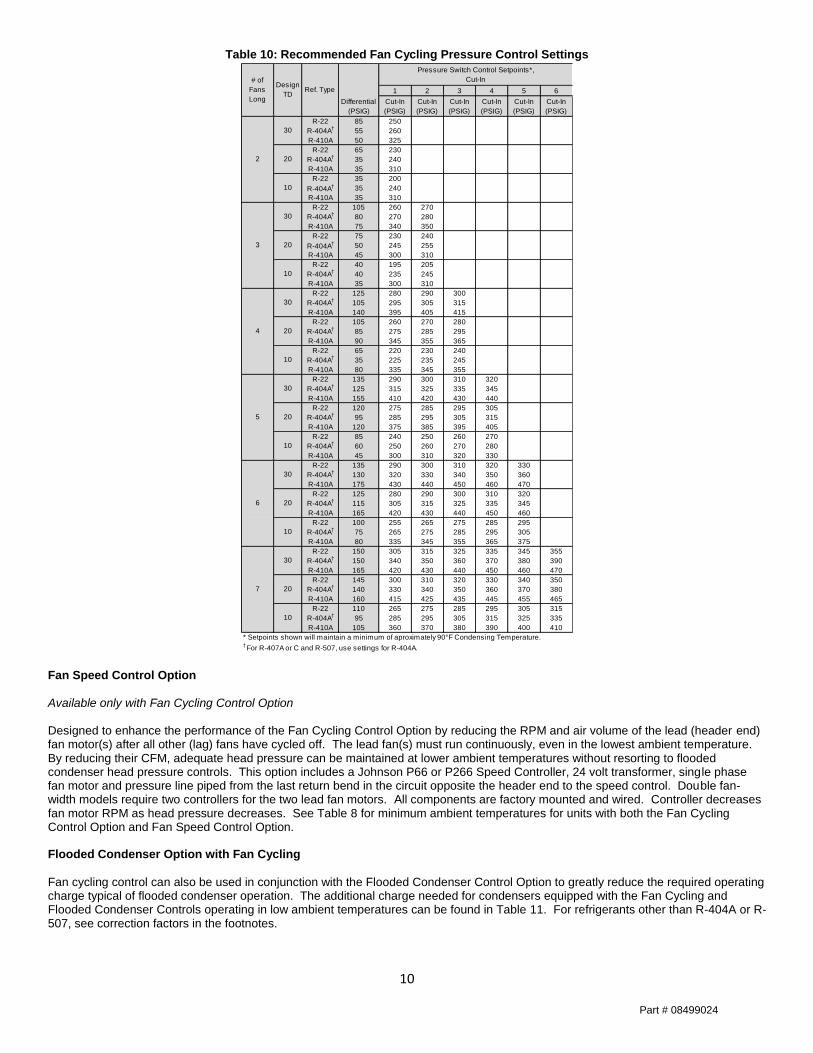
Table 10: Recommended Fan Cycling Pressure Control Settings
Fan Speed Control Option
Available only with Fan Cycling Control Option Designed to enhance the performance of the Fan Cycling Control Option by reducing the RPM and air volume of the lead (header end) fan motor(s) after all other (lag) fans have cycled off. The lead fan(s) must run continuously, even in the lowest ambient temperature. By reducing their CFM, adequate head pressure can be maintained at lower ambient temperatures without resorting to flooded condenser head pressure controls. This option includes a Johnson P66 or P266 Speed Controller, 24 volt transformer, single phase fan motor and pressure line piped from the last return bend in the circuit opposite the header end to the speed control. Double fan-width models require two controllers for the two lead fan motors. All components are factory mounted and wired. Controller decreases fan motor RPM as head pressure decreases. See Table 8 for minimum ambient temperatures for units with both the Fan Cycling Control Option and Fan Speed Control Option. Flooded Condenser Option with Fan Cycling
Fan cycling control can also be used in conjunction with the Flooded Condenser Control Option to greatly reduce the required operating charge typical of flooded condenser operation. The additional charge needed for condensers equipped with the Fan Cycling and Flooded Condenser Controls operating in low ambient temperatures can be found in Table 11. For refrigerants other than R-404A or R-507, see correction factors in the footnotes.
1 2 3 4 5 6
Differential
(PSIG)
Cut-In
(PSIG)
Cut-In
(PSIG)
Cut-In
(PSIG)
Cut-In
(PSIG)
Cut-In
(PSIG)
Cut-In
(PSIG)
R-22 85 250
R-404A†
55 260
R-410A 50 325
R-22 65 230
R-404A†
35 240
R-410A 35 310
R-22 35 200
R-404A† 35 240
R-410A 35 310
R-22 105 260 270
R-404A†
80 270 280
R-410A 75 340 350
R-22 75 230 240
R-404A† 50 245 255
R-410A 45 300 310
R-22 40 195 205
R-404A†
40 235 245
R-410A 35 300 310
R-22 125 280 290 300
R-404A†
105 295 305 315
R-410A 140 395 405 415
R-22 105 260 270 280
R-404A†
85 275 285 295
R-410A 90 345 355 365
R-22 65 220 230 240
R-404A†
35 225 235 245
R-410A 80 335 345 355
R-22 135 290 300 310 320
R-404A†
125 315 325 335 345
R-410A 155 410 420 430 440
R-22 120 275 285 295 305
R-404A†
95 285 295 305 315
R-410A 120 375 385 395 405
R-22 85 240 250 260 270
R-404A†
60 250 260 270 280
R-410A 45 300 310 320 330
R-22 135 290 300 310 320 330
R-404A†
130 320 330 340 350 360
R-410A 175 430 440 450 460 470
R-22 125 280 290 300 310 320
R-404A†
115 305 315 325 335 345
R-410A 165 420 430 440 450 460
R-22 100 255 265 275 285 295
R-404A†
75 265 275 285 295 305
R-410A 80 335 345 355 365 375
R-22 150 305 315 325 335 345 355
R-404A†
150 340 350 360 370 380 390
R-410A 165 420 430 440 450 460 470
R-22 145 300 310 320 330 340 350
R-404A†
140 330 340 350 360 370 380
R-410A 160 415 425 435 445 455 465
R-22 110 265 275 285 295 305 315
R-404A†
95 285 295 305 315 325 335
R-410A 105 360 370 380 390 400 410
* Setpoints shown will maintain a minimum of aproximately 90°F Condensing Temperature.† For R-407A or C and R-507, use settings for R-404A.
Ref. Type
# of
Fans
Long
Design
TD
Pressure Switch Control Setpoints*,
Cut-In
6
30
20
10
2
30
20
10
30
20
10
3
7
30
20
10
4
30
20
10
5
30
20
10
Part # 08499024
11
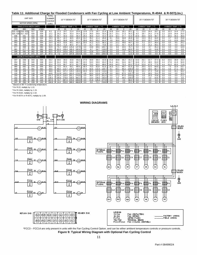
Table 11: Additional Charge for Flooded Condensers with Fan Cycling at Low Ambient Temperatures, R-404A & R-507(Lbs.)
WIRING DIAGRAMS
*FCC3 – FCC14 are only present in units with the Fan Cycling Control Option, and can be either ambient temperature controls or pressure controls.
Figure 9: Typical Wiring Diagram with Optional Fan Cycling Control
1140 850 550 VSEC 40 20 0 -20 40 20 0 -20 40 20 0 -20 40 20 0 -20 40 20 0 -20
015, 019 016, 023 017 026 8.1 17.3 19.7 21.4 22.8 13.9 17.5 19.7 21.4 10.9 15.4 18.1 20.1 7.1 13.0 16.4 18.7 3.0 10.3 14.4 17.2
020, 028 017, 027 020 029 12.2 26.2 29.7 32.3 34.4 21.0 26.5 29.9 32.5 15.7 23.1 27.3 30.3 8.3 18.7 24.2 27.9 2.2 13.9 20.9 25.4
036 031 022 038 16.2 35.7 40.3 43.6 46.4 29.4 36.6 41.0 44.3 22.0 32.1 37.7 41.6 10.5 26.5 33.9 38.7 2.2 20.5 30.2 36.0
041 039 028 044 18.3 35.7 42.2 46.5 49.9 24.2 35.2 41.4 45.8 8.1 25.6 34.8 40.8 0.0 13.3 26.3 34.5 0.0 3.7 16.5 26.8
050 049 032 051 24.3 48.0 56.8 62.6 67.1 28.8 46.3 55.2 64.4 4.6 30.0 45.1 54.0 0.0 10.0 29.7 43.4 0.0 0.3 13.5 29.3
053 051 037 054 24.4 43.3 53.6 60.1 65.0 20.0 41.2 51.5 58.3 0.0 22.2 39.6 49.7 0.0 5.1 23.7 38.4 0.0 0.0 9.5 25.1
065 058 043 066 32.4 56.4 71.6 80.5 87.1 0.4 31.7 60.5 73.8 0.0 14.1 43.7 61.8 0.0 0.0 15.2 38.2 0.0 0.0 0.0 16.1
077 069 050 080 50.9 75.7 108.0 125.6 137.9 0.0 19.8 68.6 100.7 0.0 8.6 43.5 76.7 0.0 0.0 9.7 35.4 0.0 0.0 0.0 10.5
081 077 052 083 69.6 83.3 139.4 165.3 182.6 0.0 6.7 54.7 118.0 0.0 0.0 24.8 69.5 0.0 0.0 0.0 16.8 0.0 0.0 0.0 0.0
096 092 062 098 83.5 37.4 143.6 185.2 210.0 0.0 10.8 72.7 138.5 0.0 0.0 2.2 34.1 0.0 0.0 0.0 0.0 0.0 0.0 0.0 0.0
124 114 071 127 97.4 7.2 127.0 197.8 233.4 0.0 0.0 35.5 108.4 0.0 0.0 0.0 12.0 0.0 0.0 0.0 0.0 0.0 0.0 0.0 0.0
047 048 043 034 16.2 34.6 39.3 42.8 45.6 27.9 34.9 39.4 42.8 21.8 30.8 36.2 40.2 14.3 26.1 32.7 37.4 6.0 20.6 28.9 34.4
054 052 040 048 24.4 52.4 59.5 64.6 68.7 42.0 53.0 59.9 65.0 31.4 46.1 54.6 60.7 16.6 37.4 48.5 55.9 4.4 27.8 41.9 50.9
066 059 044 055 32.4 71.5 80.7 87.3 92.7 58.8 73.2 82.0 88.6 44.0 64.3 75.3 83.2 21.0 52.9 67.9 77.5 4.4 41.0 60.4 71.9
080 082 076 056 36.6 71.5 84.4 93.1 99.9 48.4 70.3 82.8 91.6 16.3 51.1 69.7 81.6 0.0 26.5 52.5 68.9 0.0 7.5 32.9 53.7
099 101 091 064 48.6 96.0 113.7 125.2 134.3 57.6 92.6 110.4 128.7 9.1 60.1 90.2 108.0 0.0 19.9 59.5 86.7 0.0 0.6 27.1 58.7
108 109 103 074 48.8 86.6 107.2 120.2 130.0 40.0 82.3 102.9 116.6 0.0 44.4 79.1 99.5 0.0 10.1 47.4 76.8 0.0 0.0 19.1 50.2
132 134 118 086 64.8 112.8 143.1 161.0 174.2 0.8 63.4 121.0 147.6 0.0 28.3 87.5 123.7 0.0 0.0 30.5 76.4 0.0 0.0 0.0 32.2
154 156 138 100 101.7 151.4 216.0 251.1 275.9 0.0 39.5 137.2 201.4 0.0 17.2 87.0 153.5 0.0 0.0 19.3 70.8 0.0 0.0 0.0 21.1
162 163 155 104 139.2 166.6 278.8 330.6 365.2 0.0 13.4 109.3 235.9 0.0 0.0 49.5 139.0 0.0 0.0 0.0 33.6 0.0 0.0 0.0 0.0
193 195 183 124 167.0 74.7 287.3 370.3 420.0 0.0 21.6 145.4 277.0 0.0 0.0 4.5 68.2 0.0 0.0 0.0 0.0 0.0 0.0 0.0 0.0
247 250 228 142 194.8 14.4 253.9 395.5 466.8 0.0 0.0 71.1 216.8 0.0 0.0 0.0 24.1 0.0 0.0 0.0 0.0 0.0 0.0 0.0 0.0† Based on 90° F condensing temperature.
* For R-22, multiply by 1.13.
* For R-134A, multiply by 1.15.
* For R-410A, multiply by 1.02.
* For R-407A or R-407C, multiply by 1.09.
DOUBLE FAN-WIDTH UNITS
30° F DESIGN TD†
MOTOR SPEED (RPM)
SINGLE FAN-WIDTH UNITS AMBIENT TEMP. (° F) AMBIENT TEMP. (° F) AMBIENT TEMP. (° F) AMBIENT TEMP. (° F) AMBIENT TEMP. (° F)
UNIT SIZE
TOTAL
SUMMER
CHARGE
(LBS.)
10° F DESIGN TD† 15° F DESIGN TD† 20° F DESIGN TD† 25° F DESIGN TD†
Part # 08499024
12
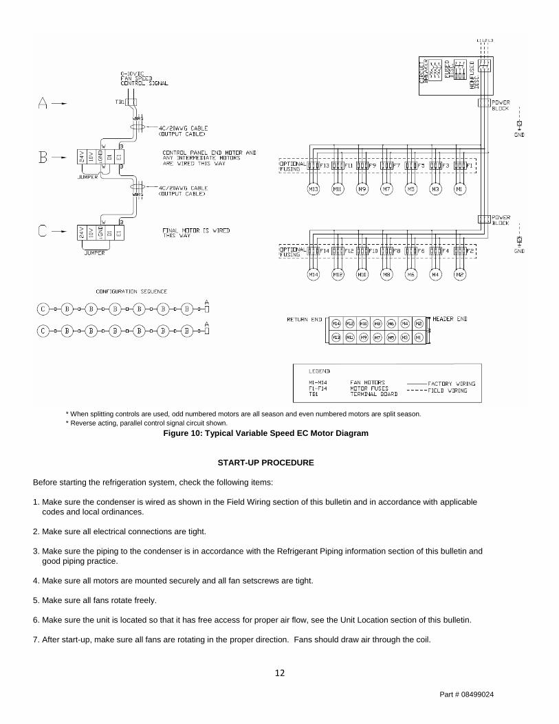
* When splitting controls are used, odd numbered motors are all season and even numbered motors are split season.
* Reverse acting, parallel control signal circuit shown.
Figure 10: Typical Variable Speed EC Motor Diagram
START-UP PROCEDURE
Before starting the refrigeration system, check the following items:
1. Make sure the condenser is wired as shown in the Field Wiring section of this bulletin and in accordance with applicable
codes and local ordinances.
2. Make sure all electrical connections are tight.
3. Make sure the piping to the condenser is in accordance with the Refrigerant Piping information section of this bulletin and
good piping practice.
4. Make sure all motors are mounted securely and all fan setscrews are tight.
5. Make sure all fans rotate freely.
6. Make sure the unit is located so that it has free access for proper air flow, see the Unit Location section of this bulletin.
7. After start-up, make sure all fans are rotating in the proper direction. Fans should draw air through the coil.
Part # 08499024
13
MAINTENANCE
General
Air-Cooled Condensers require very little maintenance. Keeping the coil surface clean and free of debris is important for
extended life, peak performance, and corrosion resistance. It is also important to periodically check all electrical connections to
make sure they are secure. All motors have permanently sealed ball bearings which do not require any maintenance.
Condenser coils should be cleaned every three months in coastal or industrial environments and every six months in all other
environments. We recommend applying clean water from a garden hose with a spray wand to the outlet side of the coil, after
using a soft-bristle brush or vaccuum cleaner to remove dirt or other fibrous material.The use of high velocity water or
compressed air could bend the coil surface, resulting in a decrease in performance. If a cleaning agent is used, make sure it is
non-acidic or non-caustic. If the coil is coated, make sure the cleaner is compatible with the coating.
"Flip-Top" Units
Cleaning the coil or servicing the fans or motors is easier on units provided with hinged "flip-top" fan panels because they can
be raised by removing five bolts with self-retained nuts. The panels are hinged and provided with pivoting rods that hold them
securely in the upright position. With the panels raised, the coil can be cleaned by washing it down from the top. Also, access
to the fans and motors is greatly improved.
Part # 08499024
14
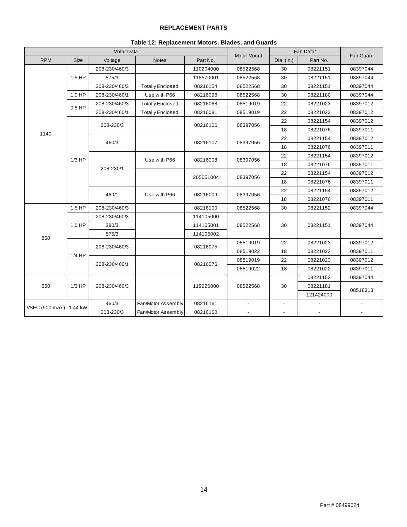
REPLACEMENT PARTS
Table 12: Replacement Motors, Blades, and Guards
RPM Size Voltage Notes Part No. Dia. (in.) Part No.
208-230/460/3 110204000 08522568 30 08221151 08397044
575/3 118570001 08522568 30 08221151 08397044
208-230/460/3 Totally Enclosed 08216154 08522568 30 08221151 08397044
1.0 HP 208-230/460/1 Use with P66 08216098 08522568 30 08221180 08397044
208-230/460/3 Totally Enclosed 08216068 08519019 22 08221023 08397012
208-230/460/1 Totally Enclosed 08216081 08519019 22 08221023 08397012
22 08221154 08397012
18 08221076 08397011
22 08221154 08397012
18 08221076 08397011
22 08221154 08397012
18 08221076 08397011
22 08221154 08397012
18 08221076 08397011
22 08221154 08397012
18 08221076 08397011
1.5 HP 208-230/460/3 08216100 08522568 30 08221152 08397044
208-230/460/3 114105000
380/3 114105001
575/3 114105002
08519019 22 08221023 08397012
08519022 18 08221022 08397011
08519019 22 08221023 08397012
08519022 18 08221022 08397011
08221152 08397044
08221181
121424000
460/3 Fan/Motor Assembly 08216161 - - - -
208-230/3 Fan/Motor Assembly 08216160 - - - -
08522568
08518318208-230/460/31/3 HP550 119226000 08522568 30
Motor DataMotor Mount Fan Guard
Fan Data*
VSEC (900 max.) 1.44 kW
1/4 HP
1140
850
1.0 HP
1/3 HP
0.5 HP
1.5 HP
208-230/3 08216106 08397056
460/3 08216107 08397056
08221151 0839704430
208-230/1
460/1 Use with P66 08216009 08397056
Use with P66 08216008 08397056
205051004 08397056
208-230/460/3
208-230/460/1
08216075
08216076
Part # 08499024
15
Date Maintenance Performed Components Required
Service Record
Part # 08499024
16
NOTES
www.htpgusa.com
Part # 08499024