INSTALLATION - OPERATING & MAINTENANCE …webmanuals.lennoxeurope.com/out of...
34
INSTALLATION - OPERATING & MAINTENANCE MANUAL Air Handling units English/10-2005
Transcript of INSTALLATION - OPERATING & MAINTENANCE …webmanuals.lennoxeurope.com/out of...

INSTALLATION - OPERATING & MAINTENANCE MANUAL
Air Handling units
English/10-2005


– Installation/Operating/Maintenance manual – 1005 – English - 1 -
INDEX 1.1 SHIPPING ............................................................................................................................ 2 1.2 OFF LOADING ..................................................................................................................... 2 1.3 SHORT DELIVERY / DEFECTS ......................................................................................... 3 1.4 INSTALLATION.................................................................................................................... 4 1.5 ASSEMBLY .......................................................................................................................... 4 1.6 SETTING UP OF COMPONENTS
1.6.1 Dampers..................................................................................................................... 5 1.6.2 Filters.......................................................................................................................... 5 1.6.3 Heat exchanger coils ................................................................................................. 5 1.6.4 Humidifiers ................................................................................................................. 7 1.6.5 Supply and return fan assembly ................................................................................ 7 1.6.6 Roof canopy ............................................................................................................... 8
1.7 DRIVE 1.7.1 Belts tension............................................................................................................... 8 1.7.2 Change of pulley ........................................................................................................ 8
1.8 MAINTENANCE 1.8.1 Once in a week .......................................................................................................... 9 1.8.2 Once in a month......................................................................................................... 9 1.8.3 Once in six months..................................................................................................... 9 1.8.4 Once in a year (preferably at the start of season) ..................................................... 9 1.8.5 Filters......................................................................................................................... 10 1.8.6 Heat exchanger coils ............................................................................................... 10 1.8.7 Supply and return fan assembly ............................................................................... 10 1.8.8 Cleaning of double skin panel................................................................................... 11
2 SAFETY
2.1 TERMINOLOGY.................................................................................................................. 12 2.2 OPERATION SAFETY ........................................................................................................ 12 2.3 USE OF THE UNIT IN CONFORMITY TO GENERAL PROVISIONS ............................... 12 2.4 STAFF TRAINING............................................................................................................... 13 2.5 USE OF THE UNIT ............................................................................................................. 13 2.6 BEHAVIOUR IN CASE OF DAMAGE ................................................................................. 13 2.7 MEASURES TAKEN BY MANUFACTURER...................................................................... 14 2.8 PREVENTION MEASURES ARE TO TAKEN BY INSTALLER OR THE PERSON
IN CHARGE OF INSTALLING CONTROL AND STURT-UP DEVICES............................. 15 2.9 RECOMMENDED SAFETY PRACTISES
2.9.1 Personnel safety accessories ................................................................................... 15 2.9.2 The hidden danger .................................................................................................... 16 2.9.3 Start up check list...................................................................................................... 17 2.9.4 After 2 weeks operation ............................................................................................ 19 2.9.5 Warning signs ........................................................................................................... 19 2.9.6 Routine maintenance ................................................................................................ 19
3 TROUBLESHOOTING
3.1 PROCEDURE FOR TROUBLESHOOTING ....................................................................... 20 3.2 SAFETY PRECAUTION...................................................................................................... 20 3.3 MASTER TROUBLESHOOTING CHART........................................................................... 20 3.4 SYSTEM CHECK LIST ....................................................................................................... 21 3.5 ADDITIONAL INFORMATION (FAN MANUFACTURER’S ANALYSIS) ............................ 23 3.6 CONCLUSION .................................................................................................................... 24 APPENDIX .................................................................................................................................... 25

– Installation/Operating/Maintenance manual – 1005 – English - 2 -
1. INSTALLATION, OPERATION AND MAINTENANCE MANUAL
1.1. SHIPPING Units are normally shipped Ex-Works. They are inspected prior to despatch for goods condition and carefully loaded in containers with no crating/boxing. Hence, in case of transit damage, the forwarder must be informed immediately. All claims must be directed to the forwarding/insurance agents and LENNOX take no responsibil-ity. When units are shipped FOB port, they are either containerised or crated and delivered FOB to forwarders. Immediately upon receipt on site, inspection should be made and any damages must be reported by telex to LENNOX as well as to the forwarding/insuring agents within 24 hrs of receipt.
1.2. OFF LOADING Special care must be taken to ensure that units are off-loaded from the containers. Rough handling can result in damage to aluminium frame work and double skin panels. It is possible to lift the sections by slings or by forklift.
Slings, preferable nylon, must be place around the struc-tural base frame as shown in fig 1.2-1.
Before lifting the section, It must be ensured that the slings are properly located so they don't slide from their slot ( see fig 1.2-2 and fig 1.2-3).
If everything is all right, then the section can
be elevated and taken away ( see fig 1.2-4 ). In the case in which is utilised a lifting tube, it must be inserted into the spe-cific hole as shown in fig 1.2-5.
fig 1.2-1
fig 1.2-2
fig 1.2-3
fig 1.2-4

– Installation/Operating/Maintenance manual – 1005 – English - 3 -
Then the sling, which is equipped with a particular loop, must be connected to the tube as shown in fig 1.2-6 and fig 1.2-7.
After that, the section can be lifted ( see fig 1.2-8 and fig 1.2-9 ).
It is necessary
to utilise slings opportunely sized on the ground of the section weight. The larger and heavier units should be lifted using a forklift with sufficiently long extended forks to prevent damaging the underside of the unit. It is strongly recommended that offloading and installation operation are carried out by specialists with neces-sary equipment and proper tools. LENNOX cannot accept responsibility for any damage sustained during off-loading and installation.
1.3. SHORT DELIVERY/DEFECTS All items must be checked against purchase order, LENNOX drawing and the packing list for correctness and any claims for non compliance or short supply or any manufacturing defects must be reported to LENNOX by telex within three days of receipt.
1.4. INSTALLATION
fig 1.2-5
fig 1.2-6
fig 1.2-7
fig 1.2-8
fig 1.2-9

– Installation/Operating/Maintenance manual – 1005 – English - 4 -
Prior to installation, it must be ensured that adequate access exists for connecting all supplies, disposal of condensate/overflows, inspection, maintenance and for replacement of renewal parts such as filters, belts, bearings etc. Installation of units must be in accordance with good engineering practise. Structural base for the units must be level and rigid. Further it must be ensured that the base is high enough from the floor to allow the installation of condensate drain with necessary trap for easy flow as show in fig 1.4-1. It is suggested to take advice for locating the suspension points for ceiling hung units.
1.5. ASSEMBLY Units are normally designed to make best use of containers ( shipping ) volume in two or more sections de-pending on the design of units. However all the sections are externally marked and their sequence of assem-bly can be easily identified from the enclosed drawings. Once all the sections are located, they can be easily aligned and locked together.
First of all, between the sides of the sections that shall be connected, it must be inserted a continuous foam gasket for airtight seal as illustrated in fig 1.5-1. Push the sections towards one another, making sure that they are lined up with one another. Consequently the sections are locked together by bolts located in factory pre-drilled assembly holes ( see fig 1.5-2 and fig 1.5-3) into the corner brackets on the inside of the frame. Make sure that they are firmly in position. Necessary stainless steel bolts and foam gaskets are supplied in a bag, normally located within the respective section.
fig 1.4-1
fig 1.5-1
fig 1.5-2
fig 1.5-3
– Installation/Operating/Maintenance manual – 1005 – English - 5 -
It must be noted that, during installation and assembly, there is a possibility of misalignment if individual sec-tions are not carefully handled. Do not use excessive force to align because it may deform the aluminium structural framework. In the case it is not possible to access the inside of the casing, the connection can be made either by opening an inspection door or by removing a wall panel. While LENNOX take no responsibility for consequences due to mishandling etc, will try to assist to ensure that units are properly installed. In case services of factory personnel are required for assembly the same can be provided at extra cost.
1.6. SETTING UP OF COMPONENTS Duct connection: when duct flanges are connected to damper frames, it must be ensured that the fixing bolts are of correct length and do not obstruct the movement of damper lever/linkages.
1.6..1. DAMPERS All dampers must be checked for free movement prior to proceeding further. 1) Manually operated dampers can be adjusted to obtain the required airflow, by loosening the bakelite knob
and then turning the control lever. Bakelite knob must be tightened after setting up at the desired location on locking quadrant.
2) Motorised dampers are supplied with the linkage rod for connection to the actuator. It must be ensured
that the actuator motors ( not supplied by LENNOX ) are rigidly fixed to the structural framework of the unit and not to the double skinned panels. Care must be taken to ensure that the actuator does not at-tempt to push the damper beyond fully open or fully closed positions.
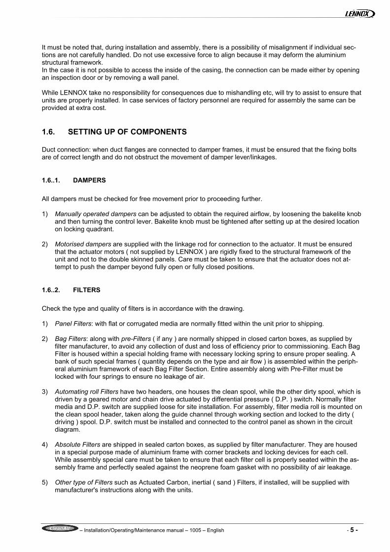
1.6..2. FILTERS Check the type and quality of filters is in accordance with the drawing. 1) Panel Filters: with flat or corrugated media are normally fitted within the unit prior to shipping. 2) Bag Filters: along with pre-Filters ( if any ) are normally shipped in closed carton boxes, as supplied by
filter manufacturer, to avoid any collection of dust and loss of efficiency prior to commissioning. Each Bag Filter is housed within a special holding frame with necessary locking spring to ensure proper sealing. A bank of such special frames ( quantity depends on the type and air flow ) is assembled within the periph-eral aluminium framework of each Bag Filter Section. Entire assembly along with Pre-Filter must be locked with four springs to ensure no leakage of air.
3) Automating roll Filters have two headers, one houses the clean spool, while the other dirty spool, which is
driven by a geared motor and chain drive actuated by differential pressure ( D.P. ) switch. Normally filter media and D.P. switch are supplied loose for site installation. For assembly, filter media roll is mounted on the clean spool header, taken along the guide channel through working section and locked to the dirty ( driving ) spool. D.P. switch must be installed and connected to the control panel as shown in the circuit diagram.
4) Absolute Filters are shipped in sealed carton boxes, as supplied by filter manufacturer. They are housed
in a special purpose made of aluminium frame with corner brackets and locking devices for each cell. While assembly special care must be taken to ensure that each filter cell is properly seated within the as-sembly frame and perfectly sealed against the neoprene foam gasket with no possibility of air leakage.
5) Other type of Filters such as Actuated Carbon, inertial ( sand ) Filters, if installed, will be supplied with
manufacturer's instructions along with the units.
– Installation/Operating/Maintenance manual – 1005 – English - 6 -
1.6..3. HEAT EXCHANGER COILS All coils are leak tested and checked prior to assembly. Fins are checked for proper condition prior to ship-ping. However during handling and installation they might be slightly bent and hence they must be checked and combed out if necessary. Do not remove plastic protective covers from the header connections until the system is ready for hook up. System layout should take into consideration of possible coil withdrawal. All con-necting pipework must be properly insulated. 1) Water Coils: system design, pipe connections and valve arrangement must be in accordance with good
engineering practice. Flow and return connections are clearly identified on the unit panels and pipe work must be connected accordingly, preferably through flexible couplings to avoid transmission of any vibra-tion from the piping to coil. Excessive tightening torque might damage the coils. Pipework must be sup-ported independently to the coil and/or the unit.
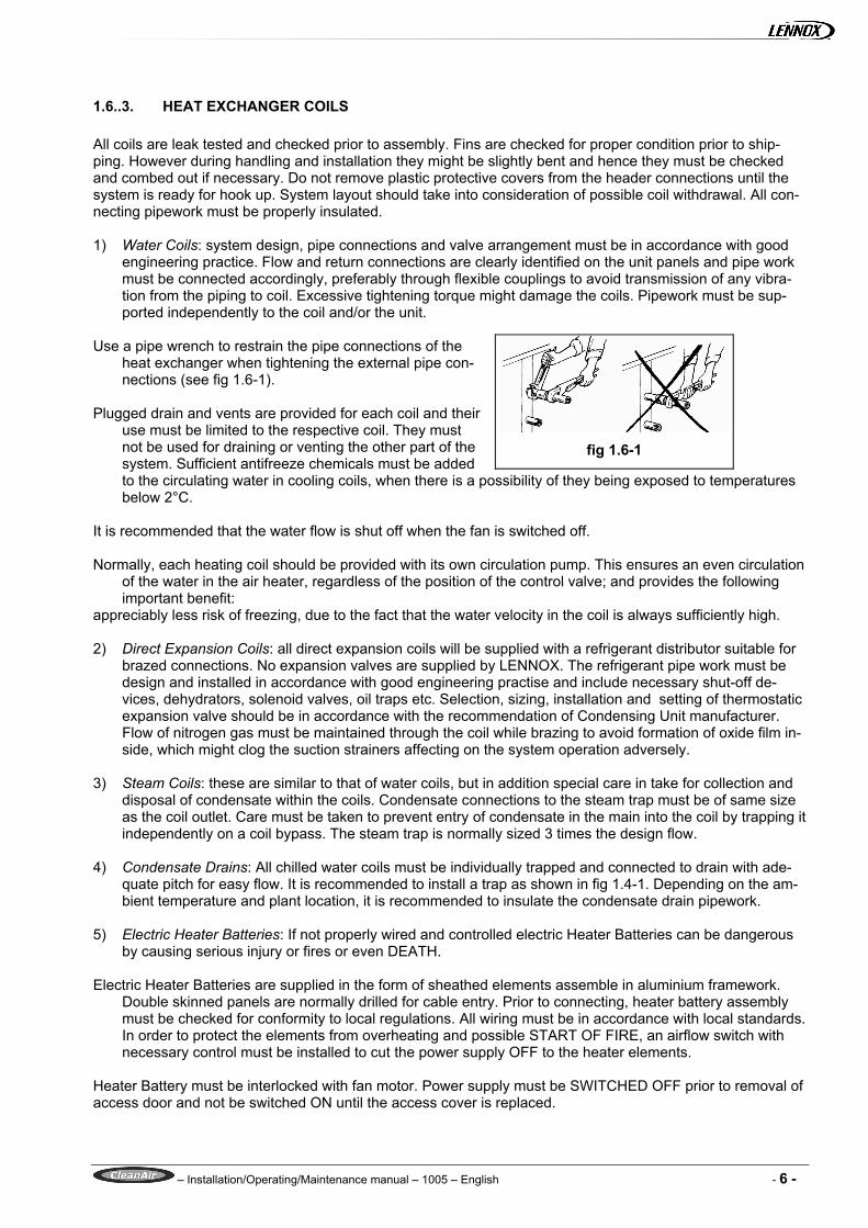
Use a pipe wrench to restrain the pipe connections of the
heat exchanger when tightening the external pipe con-nections (see fig 1.6-1).
Plugged drain and vents are provided for each coil and their
use must be limited to the respective coil. They must not be used for draining or venting the other part of the system. Sufficient antifreeze chemicals must be added to the circulating water in cooling coils, when there is a possibility of they being exposed to temperatures below 2°C.
It is recommended that the water flow is shut off when the fan is switched off. Normally, each heating coil should be provided with its own circulation pump. This ensures an even circulation
of the water in the air heater, regardless of the position of the control valve; and provides the following important benefit:
appreciably less risk of freezing, due to the fact that the water velocity in the coil is always sufficiently high. 2) Direct Expansion Coils: all direct expansion coils will be supplied with a refrigerant distributor suitable for
brazed connections. No expansion valves are supplied by LENNOX. The refrigerant pipe work must be design and installed in accordance with good engineering practise and include necessary shut-off de-vices, dehydrators, solenoid valves, oil traps etc. Selection, sizing, installation and setting of thermostatic expansion valve should be in accordance with the recommendation of Condensing Unit manufacturer. Flow of nitrogen gas must be maintained through the coil while brazing to avoid formation of oxide film in-side, which might clog the suction strainers affecting on the system operation adversely.
3) Steam Coils: these are similar to that of water coils, but in addition special care in take for collection and
disposal of condensate within the coils. Condensate connections to the steam trap must be of same size as the coil outlet. Care must be taken to prevent entry of condensate in the main into the coil by trapping it independently on a coil bypass. The steam trap is normally sized 3 times the design flow.
4) Condensate Drains: All chilled water coils must be individually trapped and connected to drain with ade-
quate pitch for easy flow. It is recommended to install a trap as shown in fig 1.4-1. Depending on the am-bient temperature and plant location, it is recommended to insulate the condensate drain pipework.
5) Electric Heater Batteries: If not properly wired and controlled electric Heater Batteries can be dangerous
by causing serious injury or fires or even DEATH. Electric Heater Batteries are supplied in the form of sheathed elements assemble in aluminium framework.
Double skinned panels are normally drilled for cable entry. Prior to connecting, heater battery assembly must be checked for conformity to local regulations. All wiring must be in accordance with local standards. In order to protect the elements from overheating and possible START OF FIRE, an airflow switch with necessary control must be installed to cut the power supply OFF to the heater elements.
Heater Battery must be interlocked with fan motor. Power supply must be SWITCHED OFF prior to removal of access door and not be switched ON until the access cover is replaced.
fig 1.6-1

– Installation/Operating/Maintenance manual – 1005 – English - 7 -
1.6..4. HUMIDIFIERS Check the type of humidifier and ensure that the necessary Water/Steam/Electric power supplies are available for connection. 1) Electric Pan Humidifier contains an electric resistance or a bank of resistance in the form of sheathed
elements, normally suitable for 3 phase power supply. All wiring must be carried out in accordance with local standards with necessary controls. Connect water supply with shut-off valves. Ensure that overflow is connected to the drainage with a necessary trap.
Important Check and clean if necessary the terminal screws etc, to ensure that there is no short circuiting between the
resistance and the cover plate or the humidifier body. 2) Steam ( Pan ) Humidifier must be connected to the steam supply with shut-off valves, inlet strainer, sole-
noid valve etc. Condesate drain must be complete with a trap. 3) Steam ( Injection ) Humidifier is normally supplied with inlet strainer, modulating valve, condensate trap,
steam injection manifold with condensate collector and discharge pipe. Ensure that the supply steam pressure is maintained within the limits marked on the modulating valve assembly and connected with a shut-off valve.
4) Air Washer is a closed circuit humidification system complete with water sump, inlet strainer, centrifugal
pump assembly, isolating valves, water distribution system made of nylon tubes and self cleaning adjust-able nozzles. Feed/Make-up water supply must be connected to the float valve with a shut-off valve. Overflow and drain connection must be complete with a trap. A common drain line may be used for over-flow and drain connections, provided a shut-off valve is installed to isolate the drain connection. Connect power supply to the pump motor in accordance with local standards with necessary controls. Check the pump impeller for free rotation.
5) Electronic Steam Humidifiers are packaged type and manufactured by others. Please refer to manufac-
turer instructions for details on installation and maintenance. 6) Eliminators: There is a remote possibility of eliminator blades being displaced from their position during
the transit/installation. In case of such occurrence, they must be set in position, which is a simple opera-tion. Further it must be ensured that no foreign matter obstruct the airflow through the eliminator.
1.6..5. SUPPLY AND RETURN FAN ASSEMBLIES Anti-vibration mounts, on which fan & motor assembly is suspended, are locked prior to shipping to avoid damage during transit ( see fig 1.6-1 ). Once the unit is in position and fan outlet is connected to ductwork, A.V. Mounts must be released. Check the type and voltage of motor. If information is made available, cable entry holes through the double skinned panels can be factory drilled. However it is a sim-ply operation to carry out the same on site, but ensure that no holes drilled and no connections are made through access door. It is recommended to use flexible armoured conduit between the panel and motor terminal box. All conduiting/wiring must be carried out in accordance with local standards. Check the type of start ( direct on line/star delta ) meets with the local electrical regulations. Provide starter/controls/overload protecting devices/interlocks as required. Manufacturer instruction, which are supplied along with the motor, must be carefully studied and followed. Duct work must be connected and insulated in accordance with good engineering practise. Depending on specified noise levels, attenuators are to be selected and installed as per the recommendations of acoustic specialists. It is recommended to protect all lining and attenuation materials with smooth perforated metallic sheets to avoid migration of fibres into occupied areas/blockage and subsequent replacement of filters fre-quently. Belt driven fans must be checked as illustrated in Chapter 3.4.
fig 1.6-2
– Installation/Operating/Maintenance manual – 1005 – English - 8 -
1.6..6. ROOF CANOPY Normally roof canopy is supplied loose to avoid damage during transit for assembly and installation on site. When units are supplied with bottom inlet and/or discharge, it must be ensured that proper flashing is carried out around base frame to avoid possible ingress of water.
1.7. DRIVE
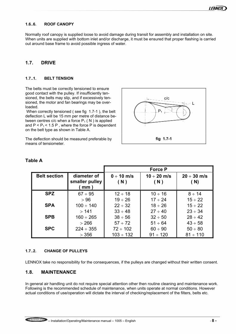
1.7..1. BELT TENSION The belts must be correctly tensioned to ensure good contact with the pulley. If insufficiently ten-sioned, the belts may slip, and if excessively ten-sioned, the motor and fan bearings may be over-loaded. When correctly tensioned ( see fig 1.7-1 ), the belt deflection L will be 15 mm per metre of distance be-tween centres c/c when a force P1 ( N ) is applied and P < P1 < 1.5 P , where the force P is dependent on the belt type as shown in Table A. The deflection should be measured preferable by means of tensiometer.
Table A
Force P Belt section diameter of
smaller pulley( mm )
0 ÷ 10 m/s ( N )
10 ÷ 20 m/s ( N )
20 ÷ 30 m/s ( N)
SPZ 67 ÷ 95 > 96
12 ÷ 18 19 ÷ 26
10 ÷ 16 17 ÷ 24
8 ÷ 14 15 ÷ 22
SPA 100 ÷ 140 > 141
22 ÷ 32 33 ÷ 48
18 ÷ 26 27 ÷ 40
15 ÷ 22 23 ÷ 34
SPB 160 ÷ 265 > 266
38 ÷ 56 57 ÷ 72
32 ÷ 50 51 ÷ 64
28 ÷ 42 43 ÷ 58
SPC 224 ÷ 355 > 356
72 ÷ 102 103 ÷ 132
60 ÷ 90 91 ÷ 120
50 ÷ 80 81 ÷ 110
1.7..2. CHANGE OF PULLEYS LENNOX take no responsibility for the consequences, if the pulleys are changed without their written consent.
1.8. MAINTENANCE In general air handling unit do not require special attention other then routine cleaning and maintenance work. Following is the recommended schedule of maintenance, when units operate at normal conditions. However actual conditions of use/operation will dictate the interval of checking/replacement of the filters, belts etc.
c/c
P1
L
fig 1.7-1

– Installation/Operating/Maintenance manual – 1005 – English - 9 -
1.8..1. ONCE IN A WEEK • Check filter condition at weekly intervals. Clean, wash or renew/replace if necessary.
1.8..2. ONCE IN A MONTH • Check fan belt tension and adjust if necessary. • Check the condition of spray nozzles and float valve in air washer. • Check the condition of drain for free flow. • Check the condition of resistance in electric Pan Humidifier. • Check the condition of access door hinges and lubricate if necessary.
1.8..3. ONCE IN SIX MONTHS • Check the fan motor running current. • Check function controls and their effect on A.H. Unit components. • Check fan and motor bearings. • Check electric heater battery elements. • Add water and flush condensate drain pan, trap and drain line. • Check circulating pump and motor in air washer. • Check the condition of inlet strainers. • Check the condition of chilled/hot water. • Add chemicals if necessary.
1.8..4. ONCE IN A YEAR ( PREFERABLY AT THE START OF SEASON ) • Check the operation of dampers. • Check the filter frame for proper sealing. • Replace synthetic media in panel filters. • Check the access doors for easy operation and proper locking. • Check the controls and operation of Roll Filters. • Check the coils and fin condition. Wash with water spray, if necessary. • Check the condition of all insulating, regulating valves etc in the system. • Vent the water coils. • Check motor and fan bearing lubrication. • Replace belts. • Check all wiring, controls, isolating devices, terminal connections etc.
– Installation/Operating/Maintenance manual – 1005 – English - 10 -
While attending to the above maintenance schedules, following must be noted.
1.8..5. FILTERS It is important to check the condition of filters once a week. When the pressure drop across the filter exceed the maximum pressure drop given in LENNOX drawing, the filter must be attended immediately. Dirty filters reduces the air flow and hence the capacity. Do not operate the system without filters. In case the media is synthetic or metallic, they can be cleaned or washed. However it is recommended to replace synthetic media once in every year and metallic media once in every two years. Other filters such as Throw Away Panels, Bag, Absolute, Roll Filters must be replaced with new cells of identical media and efficiency.
1.8..6. HEAT EXCHANGER COILS It is recommended to drain the water when the system is shut down. In case required coils can be withdrawn as follows: • Disconnect the coil from the water connection. • Remove the side ( Doubled Skin ) panel. • Remove the bolts by which coil frame is fixed to the unit frame. • Withdraw the coils. coil can be reinstalled by the following the above procedure in reverse.
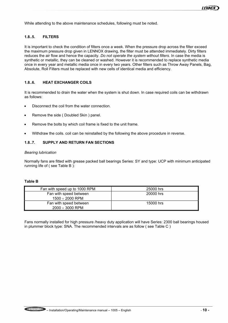
1.8..7. SUPPLY AND RETURN FAN SECTIONS Bearing lubrication Normally fans are fitted with grease packed ball bearings Series: SY and type: UCP with minimum anticipated running life of ( see Table B ):
Table B
Fan with speed up to 1000 RPM 25000 hrs Fan with speed between
1500 ÷ 2000 RPM 20000 hrs
Fan with speed between 2000 ÷ 3000 RPM
15000 hrs
Fans normally installed for high pressure /heavy duty application will have Series: 2300 ball bearings housed in plummer block type: SNA. The recommended intervals are as follow ( see Table C )

– Installation/Operating/Maintenance manual – 1005 – English - 11 -
Table C
BEARING FAN SPEED ( RPM ) HOUSING 500 1000 1500 2000 2500 3000 SNA 607 25 25 18 17 13 10 SNA 608 25 25 18 15 12 9 SNA 609 25 25 18 14 11 8 SNA 610 25 21 16 12 8 5 SNA 611 25 18 15 11 7 3 SNA 612 25 17 13 9 4 - SNA 613 25 17 12 8 2 - SNA 615 25 15 10 5 1 - SNA 616 25 13 8 2 - - SNA 617 25 12 6 1 - -
(hrs x 1000) Impeller removal For some reason, if it is required to take the impeller out for cleaning, following procedure is recommended: Forward Curved Fan • Loosen motor mounting bolts and remove the motor. • Remove belts and bearings. • Loosen the fan fixing screw and withdraw the shaft. • Unbolt the flexible connection on fan discharge. • Turn the fan assembly by 90. • Take out the impeller from the fan discharge opening. Handle carefully while cleaning, to avoid any dam-
age to blades. Backward Curved Fan • Loosen motor mounting bolts and remove the motor. • Remove belts and bearings. • Unbolt and remove the flange of bearing supporting ring frame. • Remove the aluminium inlet cone. • Withdraw the impeller along with the shaft. • Inlet cones and impellers are made of aluminium. They must be handled carefully.
1.8..8. CLEANING OF DOUBLED SKIN PANELS All panels are double skinned and they can be easily detached from the framework by removing screw with simple hand tools. They can be cleaned or washed. However it must be ensured that they are completely dry prior to refixing. Do not drop any heavy weights or sharp edge tools etc. It might damage the plasticised finish or puncture the aluminium panels. NOTE If any further information is required, please contact LENNOX, who will be very pleased to assist.
– Installation/Operating/Maintenance manual – 1005 – English - 12 -
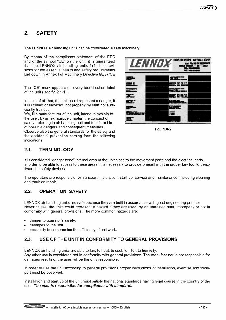
2. SAFETY The LENNOX air handling units can be considered a safe machinery. By means of the compliance statement of the EEC and of the symbol “CE” on the unit, it is guaranteed that the LENNOX air handling units fulfil the provi-sions for the essential health and safety requirements laid down in Annex I of Machinery Directive 98/37/CE . The “CE” mark appears on every identification label of the unit ( see fig 2.1-1 ). In spite of all that, the unit could represent a danger, if it is utilised or serviced not properly by staff not suffi-ciently trained. We, like manufacturer of the unit, intend to explain to the user, by an exhaustive chapter, the concept of safety referring to air handling unit and to inform him of possible dangers and consequent measures. Observe also the general standards for the safety and the accidents’ prevention coming from the following indications!
2.1. TERMINOLOGY It is considered “danger zone” internal area of the unit close to the movement parts and the electrical parts. In order to be able to access to these areas, it is necessary to provide oneself with the proper key tool to deac-tivate the safety devices. The operators are responsible for transport, installation, start up, service and maintenance, including cleaning and troubles repair.
2.2. OPERATION SAFETY LENNOX air handling units are safe because they are built in accordance with good engineering practise. Nevertheless, the units could represent a hazard if they are used, by an untrained staff, improperly or not in conformity with general provisions. The more common hazards are: • danger to operator’s safety. • damages to the unit. • possibility to compromise the efficiency of unit work.
2.3. USE OF THE UNIT IN CONFORMITY TO GENERAL PROVISIONS LENNOX air handling units are able to fan, to heat, to cool, to filter, to humidify. Any other use is considered not in conformity with general provisions. The manufacturer is not responsible for damages resulting; the user will be the only responsible. In order to use the unit according to general provisions proper instructions of installation, exercise and trans-port must be observed. Installation and start up of the unit must satisfy the national standards having legal course in the country of the user. The user is responsible for compliance with standards.
fig. 1.8-2

– Installation/Operating/Maintenance manual – 1005 – English - 13 -
Besides, it must be avoided any type of work that may compromise safety. Arbitrary transformations of the unit by user or operator are not allowed and exclude the warranty of the manu-facturer for the damages to things and persons. MEASURES OF THE USER/OPERATOR, OBSERVATION OF THE SIGNPOSTS (WARNINGS) Signposts are placed on the unit, showing: 1) prohibition to repair or adjust during motion ( fig 2.4-1 ) 2) obligation to turn off the power before opening the access door ( fig 2.4-2 ) 3) warning of coming into contact with electrical parts ( fig 2.4-3 ) This signpost and the other warnings regarding the unit must be absolutely ob-served.
2.4. STAFF TRAINING The unit can be started up and serviced (routine maintenance + corrective main-tenance) only by authorised and trained staff. This staff must be informed about
possible hazards regarding: • electrical connections • piping connections • ducting connections • start up These operations can be executed only by trained persons. People who, on behalf of the user, attend to control and to the extraordinary/ordinary main-tenance of the unit.
It is necessary to establish and to respect the responsibilities for control and maintenance to guaranty safety, without confusing competencies.
2.5. STAFF TRAINING The unit can be started up only by means of proper safety devices. The installer is obliged to install the unit according to installation plans and conditions. Only authorised persons must operate on the unit. The staff in charge is obliged to signal immediately to the user any changes that may compromise safety. For this reason it is necessary to inspect for eventual anomalies or damages at least once a week. The user or operator never must dismount and deactivate safety devices; if these would be removed for extra maintenance, at the end of operations they must be reinstalled. For all operations of extra maintenance, the power source must be locked out.
2.6. BEHAVIOUR IN CASE OF DAMAGES If it is necessary to make maintenance, the fan must be switch off, isolated and allowed to rundown.
DON’T REPAIR OR ADJUST DURING THE MOVEMENT
fig 2.3-1
TURN OFF THE POWER BEFORE OPENING
fig 2.3-2
fig 2.4-3

– Installation/Operating/Maintenance manual – 1005 – English - 14 -
2.7. MEASURES TAKEN BY MANUFACTURER: Essential Health & Safety requirements laid down in annexe I of EEC MACHINERY DIRECTIVE 98/37/EC
Applicable points of EEC MACHINERY DIRECTIVE
Measures taken: Ref. to harmonised pro-cedure
1.1.4 Lighting Inspection zone in order to provide maintenance and start-up provided with lighting
UNI EN 292
1.1.5 Design of a unit in order to handling
Design of a multi-section unit with basement for lifting by forklift or rope; locking of vibration isolators during transport
UNI EN 292
1.3.2 Risk of breakage during functioning
Operation conditions stated on the as-built drawing; frequency of mainte-nance listed in the instruction hand-book
UNI EN 292
1.3.3 Risk due to surfaces and projection of objects
Casing tested till 400 mm of pressure, fan dimensioning within operation lim-its, mesh for no ducted fan and warn-ings described in the maintenance and operation handbook
UNI EN 292
1.3.4 Risk due to surfaces, edges and corners
Sharp corner of extruded aluminium profiles rounded off to 6mm ray
UNI EN 292
1.3.7 Prevention measures against moving elements 1.3.8 Estimated prevention measures against moving ele-ments 1..41.1 General requirements 1.4.2.1 Fixed protection
Access door open able with a special tool ; written warning fitted on the ac-cess door. Optional measures are to be required during commercial agreement and stated on the as-built drawing
UNI EN 292
1.5.1 Risk due to electric power Wiring diagrams inside motor terminal box. (see also paragraph 2.9)
UNI EN 292 CEI EN 60204-1
1.5.6 Risk of fire Fire-retardant polyurethane or mineral wool panels type sandwich
UNI EN 292
1.5.7 Risk of explosion Should any risk of explosive atmos-phere, supply of electric motor and explosion-proof fan occur
UNI EN 292
1.5.8 Risk due to noise Noise level stated on the as-built drawing data sheet. Should not such noise meet given conditions, both required for machine room and other room, measures will be taken as follows: - additional insulation into section - silencer on the supply fan section
UNI EN 292
1.5.9 Risk of vibration Fans and motors mounted on base-ment isolated by vibration isolators and flexible connections on fans
UNI EN 292
1.5.14 Risk of being imprisoned inside the unit
Access door provided with hinges which allow opening from the inside
UNI EN 292
1.6.1 Maintenance of the unit See Installation, Use and Mainte-nance handbook
UNI EN 292
1.6.4 Workman corrective main-tenance
Design according to SOP 003; see chapter “Safety” in the handbook for a safety maintenance
UNI EN 292
1.7.0 Warning device Written warning in proximity to electri- UNI EN 292
– Installation/Operating/Maintenance manual – 1005 – English - 15 -
cal and rotating parts 1.7.2 Warning about further risks Written warnings near pipe connec-
tions UNI EN 292
1.7.3 Marking Marking on metal name plate dis-played on the outside the fan section access door. Operation conditions and overall di-mensions stated on the as-built draw-ing.
UNI EN 292
1.7.4 Information for use Installation, Use and Maintenance handbook, As-built drawings and pos-sible attached schemes form an inte-gral part of ‘Information for use’.
UNI EN 292
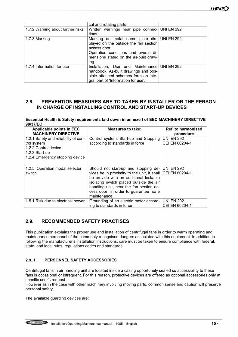
2.8. PREVENTION MEASURES ARE TO TAKEN BY INSTALLER OR THE PERSON IN CHARGE OF INSTALLING CONTROL AND START-UP DEVICES
Essential Health & Safety requirements laid down in annexe I of EEC MACHINERY DIRECTIVE 98/37/EC
Applicable points in EEC MACHINERY DIRECTIVE
Measures to take: Ref. to harmonised procedure
1.2.1 Safety and reliability of con-trol system 1.2.2 Control device 1.2.3 Start-up 1.2.4 Emergency stopping device
Control system, Start-up and Stopping according to standards in force
UNI EN 292 CEI EN 60204-1
1.2.5 Operation modal selector switch
Should not start-up and stopping de-vices be in proximity to the unit, it shall be provide with an additional lockable isolating switch placed outside the air handling unit, near the fan section ac-cess door in order to guarantee safe maintenance.
UNI EN 292 CEI EN 60204-1
1.5.1 Risk due to electrical power Grounding of an electric motor accord-ing to standards in force
UNI EN 292 CEI EN 60204-1
2.9. RECOMMENDED SAFETY PRACTISES This publication explains the proper use and installation of centrifugal fans in order to warm operating and maintenance personnel of the commonly recognised dangers associated with this equipment. In addition to following the manufacturer's installation instructions, care must be taken to ensure compliance with federal, state and local rules, regulations codes and standards.
2.9..1. PERSONNEL SAFETY ACCESSORIES Centrifugal fans in air handling unit are located inside a casing opportunely sealed so accessibility to these fans is occasional or infrequent. For this reason, protective devices are offered as optional accessories only at specific user's request. However as in the case with other machinery involving moving parts, common sense and caution will preserve personal safety. The available guarding devices are:

– Installation/Operating/Maintenance manual – 1005 – English - 16 -
1) Lockout switches and suitable warnings. In such cases, maintenance personnel should engage the lock-out switch before undertaking any maintenance or repairs.
2) Inlet and outlet guards. Centrifugal fans are usually con-
nected directly to ductwork which will prevent the contact with the internal moving parts. In case there is an exposed inlet or outlet which could represent a danger, It can be in-stalled a suitable guard as the one represented in fig 2.10-1.
3) Drive guards. A typical centrifugal fan drive guard may
vary with the arrangement. Safety guards shall be used when drive systems are accessible to personnel ( see fig 2.10-2).In restricted areas, omission of the back cover may be acceptable.
2.9..2. THE HIDDEN DANGER In addition to the dangers of rotating machinery, fans present another potential danger by virtue of their ability to draw in loose material. Solid ob-jects passing through a fan represent potentially dangerous projectiles. Solid objects can cause fan failure by physically damaging the impeller blades. Whatever there is the possibility of solid objects being drawn into a remote intake, the intake shall be guarded at all this times. In the event the guard is removed for any reason, the fan must be disconnected and locked out. Where fans are installed over an occupied area, safety guards should be provided to prevent dropped objects from entering this area during installation and maintenance. Access doors to a fan or duct system should not be opened with the fan in operation or coasting to a stop. Power shall be locked out prior to access into a fan or ductwork. Even when locked out electrically, fans may cause injury or damage if the impeller is subject to "wind milling". The impeller should be secured to physically restrict rotational movement. On the downstream (or pressure) side of the system, realising the door with the system in operation may re-sult in an explosive opening. On the upstream (or suction) side the inflow may be sufficient to draw in tools and clothing, etc, and create a danger. The access door in air handling unit is always locked out by a special lock and to open the door it is necessary a key so it is impossible to open it by chance.
fig 2.9-1: inlet or outlet guard on centrifugal fan
fig 2.9-2: drive guard- centrifugal fan
fig 2.9-3: special purpose intake screen
– Installation/Operating/Maintenance manual – 1005 – English - 17 -
The stroboscopic effect of certain lights in combination with certain fan speeds may cause a rotating assembly to appear stopped.
2.9..3. START UP CHECK LIST Before putting any fan into operation the manufacturers' instructions must be followed. In addition, the follow-ing check list must be completed. • There is possibility of collection of debris such as duct/insulation materials, tapes etc used during installa-
tion of the system. Hence it must be ensured that all the sections of the unit are thoroughly cleaned. In case units are supplied with peraluman panels, polythene protective film must be peeled off and it must be ensured that no traces of film is left loose within the unit.
• Ensure all panels, if removed during installation, are in position. • Ensure all electrical wiring in carried out to local standards and all components are provided with safety,
protecting and isolating devices. • Remove all filters including panel filters: install low efficiency filters such as gauze bags or a set of throw
away type filters. • Ensure all dampers are opened. • Check water/steam/refrigerant coil connection for any leaks. Ensure that all the air in the system and coil
is vented out. Check coil face free from debris. • Add water in the condensate drain pan to prime the trap and ensure free flow of water into the drain. • Ensure that minimum water levels are maintained in electrical Pan Humidifier/Air Washers. Fan start up 1) Screw out security nuts of antivibration mounts. 2) Lock out the primary and secondary power sources. 3) A complete inspection shall be made of all the ductwork and the interior of the fan. Make certain there is
no foreign material which can be drawn into or blown through the fan or ductwork. Eyes should be pro-tected against undetected foreign material through the use of safety goggles or other appropriate means.
4) Make sure the foundation or mounting arrangement and the duct connection are adequately designed in accordance with recognised acceptable engineering practises and with the fan manufacturer's recom-mendations.
5) Check and tighten all hold-down (securing) bolts. 6) Check the fan assembly and bearings for proper grounding to prevent static electricity discharge. 7) Spin the impeller to determine whether it rotates freely and is not grossly out of balance. 8) Inspect impeller for proper rotation for the fan design. 9) Check all set screws and tighten, if necessary. 10) Check belt drive or coupling alignment; use recommended belt tension. 11) Check the belt drive for proper sheave selection and make sure they are not reversed ( excessive
speeds could develop ). 12) Properly secure all safety guards. 13) Secure all access door to the fan and ductwork. 14) Momentarily energise the fan to check the direction of rotation. 15) Switch on the electrical supply and allow the fan to reach full speed. Check carefully for:
a) Excessive vibration b) Unusual noise c) Proper belt alignment d) Proper lubrication
– Installation/Operating/Maintenance manual – 1005 – English - 18 -
e) Proper amperage and voltage values If any problem is indicated, SWITCH OFF IMMEDIATELY. Lock out the electrical supply, secure the fan impeller if there is a potential for windmilling ( impeller turning due to a draft through the system ).Check carefully for the cause of the trouble and correct as necessary. Even if the fan appears to be operating satisfactory, shut down after a brief period and recheck items 5) through 12) as the initial start up may have loosened the bolts and set screws. • After ensuring that there are no leaks between joints of section and system is clean, stop the fan. Dispose
off low efficiency filters. Install Panel/Bag/Absolute filters, as supplied. • Restart the fan. In case of a stand-by fan and motor are supplied, ensure that no short circuiting of air oc-
curs. • In case fan is connected to a stand by motor for automatic change over, do not touch the terminal of
stand by motor, even though motor is idle. Ensure that belts are removed and the power is isolated. • Adjust dampers position to obtain the rated air volume. • In case fans are supplied with variable pitch pulley ( up to 7.5 kW ), adjust the same to the desired posi-
tion. • Ensure that the air volume are within the specified limits. • Check the motor current and ensure the same is within the rated ( name plate ) data. • Check ON-OFF temperature across coils and adjust water/steam flows accordingly. Check the function-
ing of controls. • Check the functioning of humidifier by adjusting the humidistat control. • Check the operation of heater batteries by adjusting thermostat. Check the functioning of controls such as
air flow switch, fan interlock, over heat protection etc. • Check the pressure drop across the filters and ensure that the same is within the limits. The fan has been put into operation but, during the first eight hours of running, it should be periodically ob-served and checked for excessive vibration and noise. At this time checks should also be made of motor input current and motor and bearing temperatures to ensure that they do not exceed manufacturer's recommenda-tions. After eight hours of satisfactory operation, the fan should be shut down to check the following items and ad-just, if necessary ( lock-out power ). 1) All set screws and hold-down bolts 2) Drive coupling alignment 3) Belt drive alignment 4) Bearing housing temperature 5) Belt drive tension After twenty-four hours of satisfactory operation the fan should be shut down ( locked out ) and the drive belt tension should be readjusted to recommended tension.

– Installation/Operating/Maintenance manual – 1005 – English - 19 -
2.9..4. AFTER 2 WEEKS OPERATION After start up and initial operation of approximately 2 weeks, it is recommended to have the following checks. • Bearings temperature immediately after stoppage. This is not to exceed 70°C; Lubricate if necessary. • Belt tension. • Pulley alignment. • Motor running current. • Filter condition. • Condensate and drain to see flow. • Operation of controls.
WARNING SIGNS A preventive maintenance program is an important aspect of an effective safety program. Investigate any changes to the fan. Refer to Chapter 3 “troubleshooting”, for a more detailed explanation of investigating pro-cedures. Consult your manufacturer or other qualified consultant with question concerning changes observed during periodic inspections. 1) Excessive vibration: if excessive vibration is observed stop the fan until the cause is corrected. Check for
material build-up on impeller. Generally this will show up as material flaking off the fan impeller and caus-ing an imbalance which may lead to fatigue failure of the impeller.
2) Noise: changes to the sound level may indicate troubleshooting is needed. 3) High motor temperatures: check that cooling air to the motor has not been deviated or blocked by dirty
guards or similar obstacles. Check the input amperage. An increase in amperage may indicate that some major changes has been made in the system.
4) High bearing temperatures: this condition is usually caused by improper lubrication; this can be either
"over", "under" or "unsuitable" lubrication. In any case if the cause of the trouble is not easily seen, experi-enced personnel must examine the equipment before it is put back in operation.
2.9.6. ROUTINE MAINTENANCE Maintenance should be performed by experienced and trained personnel. Do not attempt maintenance unless the electrical supply has been locked out or tagged out and the impeller has been secured. a) Under normal circumstances, handling clean air, the system should require cleaning only about once a
year. However, the fan and the system should be checked at regular intervals to detect any unusual ac-cumulation.
b) The fan impeller should be especially checked for build-up of material or dirt which may cause an imbal-
ance with resulting undue wear on bearings and belt drives. A regular maintenance program should be es-tablished as needed to prevent material build up.
Periodic inspection of the rotating assembly must be made to detect any indication of weakening of the rotor because of corrosion, erosion, or metal fatigue.

– Installation/Operating/Maintenance manual – 1005 – English - 20 -
3. TROUBLESHOOTING A preventive maintenance program is an important aspect of an effective safety program. It is fundamental to keep any part of the system controlled in order to point out promptly any changes to the right working. In any case it is suitable to consult the manufacturer or other qualified consultant with ques-tion concerning changes observed during periodic inspections.
3.1. PROCEDURE FOR TROUBLESHOOTING 1) Look in the "Master Troubleshooting Chart" for an index tag which corresponds to with the apparent
problem. 2) Check each of the probable causes listed. 3) If the cause of the trouble is not found proceed through the "System Checklist". 4) If the problem has still not be solved, it is now advisable to contact the representative of fan manufac-
turer. He should be given the results of the "System Checklist" and some "additional information" which are particularly interesting for the manufacturer.
5) The fan manufacturer or his representative will analyse the information submitted (as outlined on page 31 ).With this information and, if necessary, an on-site inspection he should be able to explain why the system is not achieving its design performance and may recommend changes in the system or the fan installation which will overcome the problem.
3.2. SAFETY PRECAUTION Before checking the fan and system it will be necessary to shut down the fan. During inspection the fan must be electrically isolated and all disconnect switches and others controls locked in the "OFF" position. Where this in location remote from the fan, prominent "DO NOT START" signs should also be in place.
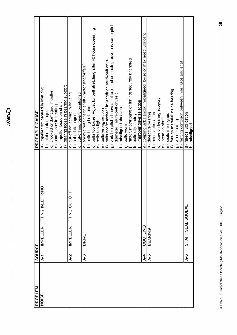
3.3. MASTER TROUBLESHOOTING CHART See Appendix SYSTEM CHECKLIST Poor system performance may arise from a number of causes including: • improper installation or assembly of the fan • damage in handling or transit • system design error • deterioration of the system • faulty controls • poor fan selection • a combination of several factor A systematic check of items listed should identify the problem or problems and allow suitable corrective action to be taken.
– Installation/Operating/Maintenance manual – 1005 – English - 21 -
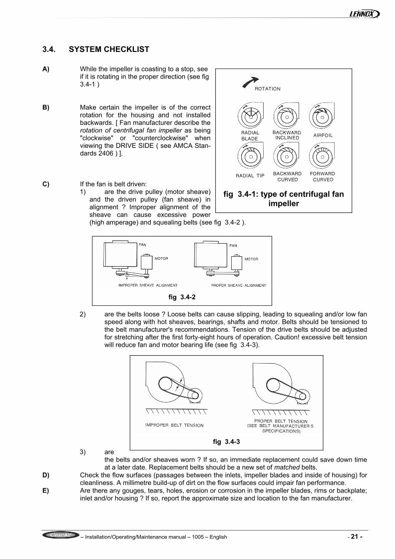
3.4. SYSTEM CHECKLIST A) While the impeller is coasting to a stop, see
if it is rotating in the proper direction (see fig 3.4-1 )
B) Make certain the impeller is of the correct
rotation for the housing and not installed backwards. [ Fan manufacturer describe the rotation of centrifugal fan impeller as being "clockwise" or "counterclockwise" when viewing the DRIVE SIDE ( see AMCA Stan-dards 2406 ) ].
C) If the fan is belt driven:
1) are the drive pulley (motor sheave) and the driven pulley (fan sheave) in alignment ? Improper alignment of the sheave can cause excessive power (high amperage) and squealing belts (see fig 3.4-2 ).
2) are the belts loose ? Loose belts can cause slipping, leading to squealing and/or low fan speed along with hot sheaves, bearings, shafts and motor. Belts should be tensioned to the belt manufacturer's recommendations. Tension of the drive belts should be adjusted for stretching after the first forty-eight hours of operation. Caution! excessive belt tension will reduce fan and motor bearing life (see fig 3.4-3).
3) are the belts and/or sheaves worn ? If so, an immediate replacement could save down time at a later date. Replacement belts should be a new set of matched belts.
D) Check the flow surfaces (passages between the inlets, impeller blades and inside of housing) for cleanliness. A millimetre build-up of dirt on the flow surfaces could impair fan performance.
E) Are there any gouges, tears, holes, erosion or corrosion in the impeller blades, rims or backplate; inlet and/or housing ? If so, report the approximate size and location to the fan manufacturer.
fig 3.4-1: type of centrifugal fan
impeller
fig 3.4-2
fig 3.4-3

– Installation/Operating/Maintenance manual – 1005 – English - 22 -
F) Is any foreign matter trapped in the impeller, housing or ductwork (loose insulation, papers, ice, etc) ? If so, remove.
G) Are coils, heaters, filters, ducts, etc dirt laden ? If so, clean or replace. Remove any non-essential obstruction to flow in elbows, shutters, transformations, dampers, bird-screens, etc.
H) Have all the parts supplied with the fan been installed ? I) Are there any obstruction to flow near the fan inlets ? Objects such as pipes, ductwork, columns,
belt guards, belt drives, etc could adversely affect the output of the fan. J) Are the fan outlet connections correctly designed and installed ? Duct takeoffs, or obstructions in
the fan outlet could adversely affect the output of the fan. K) See fig 3.4-4 for typical inlet-impeller relationships. A few simple measurements as indicated on
fig 3.4-4 can tell the manufacturer if a problem exists in this area (several measurement should be taken around the entire inlet circumference).
D) Are turning vanes installed in elbows close to the fan inlet or discharge ? E) If the fan is equipped with variable inlet vane or inlet damper control, check the operation as fol-
lows: 1) Do not rely on the control arm position alone for locating the position of the vane/damper
blades without first checking visually to see that the vane/damper position agrees with the position of the control arm.
2) If the unit is double width fan equipped with variable inlet vanes or damper control, both inlet vanes/dampers must be synchronised (the inlet vanes/dampers must be in the same relative position with respect to the impeller on both inlets). If the inlet vanes/dampers are not synchronised, there will be an unbalance flow between inlets resulting in deficient air performance, unbalance thrust on bearing and/or a surge condition in the fan.
3) Make certain that variable inlet vanes are of the proper rotation with respect to the impel-ler. As the vanes close, they should cause the entering air to spin in the same direction as the impeller.
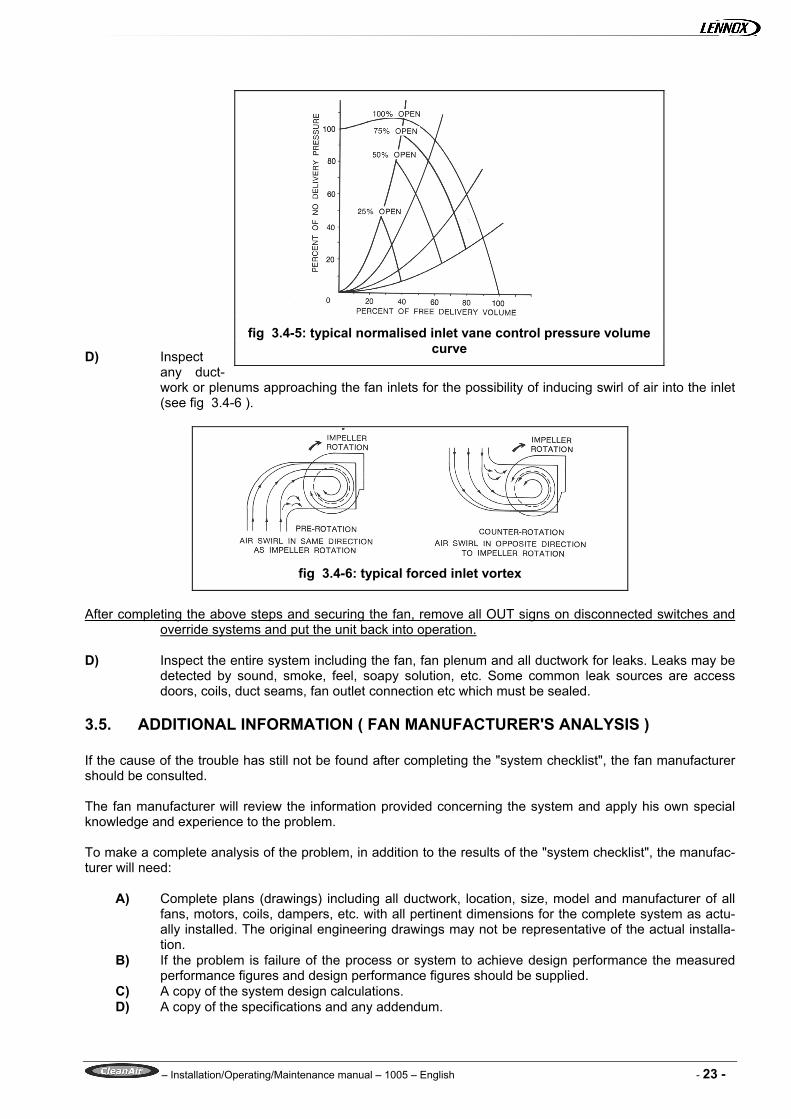
4) Are the inlet vanes/dampers correctly positioned for the designed operating conditions ? If not, the desired pressure-volume of the fan will not be realised (see fig 3.4-5).
fig 3.4-4: typical inlet-impeller relationships
– Installation/Operating/Maintenance manual – 1005 – English - 23 -
D) Inspect
any duct-work or plenums approaching the fan inlets for the possibility of inducing swirl of air into the inlet (see fig 3.4-6 ).
After completing the above steps and securing the fan, remove all OUT signs on disconnected switches and
override systems and put the unit back into operation. D) Inspect the entire system including the fan, fan plenum and all ductwork for leaks. Leaks may be
detected by sound, smoke, feel, soapy solution, etc. Some common leak sources are access doors, coils, duct seams, fan outlet connection etc which must be sealed.
3.5. ADDITIONAL INFORMATION ( FAN MANUFACTURER'S ANALYSIS ) If the cause of the trouble has still not be found after completing the "system checklist", the fan manufacturer should be consulted. The fan manufacturer will review the information provided concerning the system and apply his own special knowledge and experience to the problem. To make a complete analysis of the problem, in addition to the results of the "system checklist", the manufac-turer will need:
A) Complete plans (drawings) including all ductwork, location, size, model and manufacturer of all fans, motors, coils, dampers, etc. with all pertinent dimensions for the complete system as actu-ally installed. The original engineering drawings may not be representative of the actual installa-tion.
B) If the problem is failure of the process or system to achieve design performance the measured performance figures and design performance figures should be supplied.
C) A copy of the system design calculations. D) A copy of the specifications and any addendum.
fig 3.4-5: typical normalised inlet vane control pressure volume
curve
fig 3.4-6: typical forced inlet vortex

– Installation/Operating/Maintenance manual – 1005 – English - 24 -
E) If a separate air performance test has been conducted on the installed fan, a statement of meas-ured fan performance along with a copy of the test data, the type of test and instrumentation, and the location of the flow rate pressure determination should be supplied.
A statement of fan performance should contain:
1) fan total pressure rise or fan static pressure 2) flow rate 3) power (amperage) 4) fan speed 5) gas density
Among other actions he will:
1) Access the probable accuracy of the field performance measurements. 2) Check whether the fan selection is correct for the application. 3) Examine the system drawings (plans) in order to individualise any eventual change in the system
performance curve in respect to the system design calculations or the original fan selection. 4) Make the appropriate corrections.
3.6. CONCLUSION By intelligent application of the procedures outlined in this manual it should be possible to find the cause of performance problem in any air moving system. Identification of problem associated directly with the fan may require the assistance of the fan manufacturer. Recognition of the cause of the trouble will usually be a major step towards curing it. Corrective measures may include alterations to the system, modification to the fan outlet or inlet connections, adjustments to the fan etc. in many cases an increase in the fan speed may be decided upon but it is extremely important that the fan shall not be operated above its catalogued maximum speed or the maximum speed recommended by the manufacturer. The information obtained through the checklists in this manual should also help in allocating responsibility for the necessary corrective action. In most cases, if the troubleshooting procedure has been followed carefully and impartially it will be apparent whether the system has been built and installed in accordance with the de-sign drawings, whether the fan was properly selected, or the fan is not performing up it its published ratings.
CLE
AN
AIR
– In
stal
latio
n/O
pera
ting/
Mai
nten
ance
man
ual –
100
5 –
Eng
lish
- 25
-
PRO
BLE
M
SOU
RC
E PR
OB
AB
LE C
AU
SE
NO
ISE
A
-1
IMP
ELL
ER
HIT
TIN
G IN
LET
RIN
G
a) i
mpe
ller n
ot c
entre
d in
inle
t rin
g b)
inl
et ri
ng d
amag
ed
c) c
rook
ed o
r dam
aged
impe
ller
d) s
haft
loos
e in
bea
ring
e) i
mpe
ller l
oose
on
shaf
t f)
bear
ing
loos
e in
bea
ring
supp
ort
A
-2
IMP
ELL
ER
HIT
TIN
G C
UT
OFF
a)
cut
-off
not s
ecur
e in
hou
sing
b)
cut
-off
dam
aged
c)
cut
-off
impr
oper
ly p
ositi
oned
A-3
D
RIV
E
a) s
heav
e no
t tig
ht o
n sh
aft (
mot
or a
nd/o
r fan
) b)
bel
ts h
ittin
g be
lt tu
be
c) b
elts
too
loos
e. A
djus
t for
bel
t stre
tchi
ng a
fter 4
8 ho
urs
oper
atin
g d)
bel
ts to
o tig
ht
e) b
elts
wro
ng s
ectio
n f)
belts
not
"mat
ched
" in
leng
th o
n m
ulti-
belt
driv
e g)
var
iabl
e pi
tch
shea
ves
not a
djus
ted
so e
ach
groo
ve h
as s
ame
pitc
h di
amet
er (
mul
ti-be
lt dr
ives
) h)
mis
alig
ned
shea
ves
i)
belts
wor
n j)
mot
or, m
otor
bas
e or
fan
not s
ecur
ely
anch
ored
k)
bel
ts o
ily o
r dirt
y l)
impr
oper
driv
e se
lect
ion
A
-4
CO
UP
LIN
G
a) c
oupl
ing
unba
lanc
ed, m
isal
igne
d, lo
ose
or m
ay n
eed
lubr
ican
t
A-5
B
EA
RIN
G
a) d
efec
tive
bear
ing
b) n
eeds
lubr
icat
ion
c) l
oose
on
bear
ing
supp
ort
d) l
oose
on
shaf
t e)
sea
ls m
isal
igne
d f)
fore
ign
mat
eria
l ins
ide
bear
ing
g) w
orn
bear
ing
h) f
retti
ng c
orro
sion
bet
wee
n in
ner r
ace
and
shaf
A-6
S
HA
FT S
EA
L S
QU
EA
L a)
nee
ds lu
bric
atio
n b)
mis
alig
ned

CLE
AN
AIR
– In
stal
latio
n/O
pera
ting/
Mai
nten
ance
man
ual –
100
5 –
Eng
lish
- 26
-
PR
OB
LEM
SO
UR
CE
PRO
BA
BLE
CA
USE
N
OIS
E
A-7
IM
PE
LLE
R
a) l
oose
on
shaf
t b)
def
ectiv
e im
pelle
r. D
o no
t run
the
fan.
Con
tact
man
ufac
ture
r c)
unb
alan
ce
d) c
oatin
g lo
ose
e) w
orn
as re
sult
of a
bras
ive
or c
orro
sive
mat
eria
l mov
ing
thro
ugh
flo
w p
assa
ges
A
-8
HO
US
ING
a)
for
eign
mat
eria
l in
hous
ing
b) c
ut-o
ff or
oth
er p
art l
oose
( ra
ttlin
g du
ring
oper
atio
n )
A
-9
ELE
CTR
ICA
L a)
lea
d-in
cab
le n
ot s
ecur
e b)
AC
hum
in m
otor
or r
elay
c)
sta
rting
rela
y ch
atte
r d)
noi
sy m
otor
bea
rings
e)
sin
gle
phas
ing
a 3
phas
e m
otor
A-1
0 S
HA
FT
a) b
ent
b) u
nder
size
d. M
ay c
ause
noi
se a
t im
pelle
r, be
arin
g or
she
ave.
c)
if m
ore
than
two
bear
ings
are
on
shaf
t, th
ey m
ust b
e pr
oper
ly a
ligne
d.
A
-11
HIG
H A
IR V
ELO
CIT
Y
a) d
uct w
ork
too
smal
l for
app
licat
ion
b) f
an s
elec
tion
too
smal
l for
app
licat
ion
c) r
egis
ter o
r gril
les
too
smal
l for
app
licat
ion
d) h
eatin
g or
coo
ling
coils
with
insu
ffici
ent f
ace
area
for a
pplic
atio
n
A-1
2 O
BS
TRU
CTI
ON
IN H
IGH
VE
LOC
ITY
GA
S
STR
EA
M M
AY
CA
US
E R
ATT
LE, O
R P
UR
E T
ON
E
WH
ISTL
E
a) d
ampe
rs
b) r
egis
ters
c)
gril
les
d) s
harp
elb
ows
e) s
udde
n ex
pans
ion
in d
uct w
ork
f) su
dden
con
tract
ion
in d
uct w
ork
g) t
urni
ng v
anes
A-1
3 P
ULS
ATI
ON
OR
SU
RG
E
a) r
estri
cted
sys
tem
cau
ses
to o
pera
te a
t poo
r poi
nt o
f rat
ing
b) f
an to
o la
rge
for a
pplic
atio
n c)
duc
ts v
ibra
te a
t sam
e fre
quen
cy a
s fa
n pu
lsat
ion
A
-14
GA
S V
ELO
CIT
Y T
HR
OU
GH
CR
AC
KS
, HO
LES
OR
P
AS
T O
BS
TRU
CTI
ON
S
a) l
eaks
in d
uct w
ork
b) f
ins
on c
oils
c)
reg
iste
r or g
rille
s

CLE
AN
AIR
– In
stal
latio
n/O
pera
ting/
Mai
nten
ance
man
ual –
100
5 –
Eng
lish
- 27
-
PR
OB
LEM
SO
UR
CE
PRO
BA
BLE
CA
USE
N
OIS
E
A-1
5 R
ATT
LES
AN
D/O
R R
UM
BLE
S
a) v
ibra
ting
duct
wor
k b)
vib
ratin
g ca
bine
t par
ts
c) v
ibra
ting
parts
not
isol
ated
from
bui
ldin
g IN
SU
FFIC
IEN
T A
IR
FLO
W
B-1
FA
N
a) f
orw
ard
curv
ed im
pelle
r ins
talle
d ba
ckw
ards
b)
fan
runn
ing
back
war
ds
c) c
ut-o
ff m
issi
ng o
r im
prop
erly
inst
alle
d d)
im
pelle
r not
cen
tred
with
inle
t col
lar(
s)
e) f
an s
peed
too
slow
B-2
D
UC
T S
YS
TEM
a)
act
ual s
yste
m is
mor
e re
stric
tive
(mor
e re
sist
ance
to fl
ow )
than
ex-
pect
ed
b) d
ampe
rs c
lose
d c)
reg
iste
rs c
lose
d d)
lea
ks in
sup
ply
duct
s e)
ins
ulat
ing
duct
line
r loo
se
B
-3
FILT
ER
S
a) d
irty
or c
logg
ed
B
-4
CO
ILS
a)
dirt
y or
clo
gged
B-5
R
EC
IRC
ULA
TIO
N
a) i
nter
nal c
abin
et le
aks
in b
ulkh
ead
sepa
ratin
g fa
n ou
tlet (
pre
ssur
e zo
ne
) fro
m fa
n in
lets
( su
ctio
n zo
ne )
b) l
eaks
aro
und
fan
outle
t at c
onne
ctio
n th
roug
h ca
bine
t bul
khea
d
B-6
O
BS
TRU
CTE
D F
AN
INLE
TS
a) e
lbow
s, c
abin
et w
alls
or o
ther
obs
truct
ions
rest
rict a
ir flo
w. I
nlet
ob-
stru
ctio
ns c
ause
mor
e re
stric
tive
syst
ems
but d
o no
t cau
se in
crea
sed
nega
tive
pres
sure
read
ings
nea
r the
fan
inle
t(s).F
an s
peed
may
be
in-
crea
sed
to c
ount
erac
t the
effe
ct o
f res
trict
ed fa
n in
let(s
)
B-7
N
O S
TRA
IGH
T D
UC
T A
T FA
N O
UTL
ET
a) f
ans
whi
ch a
re n
orm
ally
use
d in
duc
t sys
tem
are
test
ed w
ith a
leng
th o
f st
raig
ht d
uct a
t the
fan
outle
t. If
ther
e is
no
stra
ight
duc
t at t
he fa
n ou
t-le
t, de
crea
sed
perfo
rman
ce w
ill re
sult.
If it
is n
ot p
ract
ical
to in
stal
l a
stra
ight
sec
tion
of d
uct a
t the
fan
outle
t, th
e fa
n sp
eed
may
be
in-
crea
sed
to o
verc
ome
this
pre
ssur
e lo
ss.
B
-8
OB
STR
UC
TIO
NS
IN H
IGH
VE
LOC
ITY
AIR
S
TRE
AM
a)
obs
truct
ion
near
fan
outle
t b)
sha
rp e
lbow
s ne
ar fa
n ou
tlet
c) i
mpr
oper
ly d
esig
ned
turn
ing
vane
s d)
pro
ject
ions
, dam
pers
or o
ther
obs
truct
ion
in p
art o
f sys
tem
whe
re a
ir ve
loci
ty is
hig
h

CLE
AN
AIR
– In
stal
latio
n/O
pera
ting/
Mai
nten
ance
man
ual –
100
5 –
Eng
lish
- 28
-
PR
OB
LEM
SO
UR
CE
PRO
BA
BLE
CA
USE
TO
O M
UC
H A
IR F
LOW
C
-1
SYST
EM
a) o
vers
ized
duc
t wor
k b)
acc
ess
door
ope
n c)
reg
iste
rs o
r gril
les
not i
nsta
lled
d) d
ampe
rs s
et to
by-
pass
coi
ls
e) f
ilter
(s) n
ot in
pla
ce
C
-2
FAN
a)
bac
kwar
d in
clin
ed im
pelle
r ins
talle
d ba
ckw
ards
( po
wer
will
be
high
) b)
fan
spe
ed to
o fa
st
STA
TIC
PR
ES
SU
RE
W
RO
NG
D
-1
SY
STE
M, F
AN
OR
INTE
RP
RE
TATI
ON
OF
ME
AS
UR
EM
EN
TS
gene
ral d
iscu
ssio
n:
The
velo
city
pre
ssur
e at
any
poi
nt o
f mea
sure
men
t is
a fu
nctio
n of
the
ve-
loci
ty o
f the
air
or g
as a
nd it
s de
nsity
. Th
e st
atic
pre
ssur
e at
a p
oint
of m
easu
rem
ent i
n th
e sy
stem
is a
func
tion
of s
yste
m d
esig
n ( r
esis
tanc
e to
flow
), a
ir de
nsity
and
the
amou
nt o
f air
flow
ing
thro
ugh
the
syst
em.
The
stat
ic p
ress
ure
mea
sure
d in
a "l
oose
" or o
vers
ized
sys
tem
will
be
less
than
the
stat
ic p
ress
ure
in a
"tig
ht" o
r und
ersi
zed
syst
em fo
r the
sa
me
flow
rate
. In
mos
t sys
tem
s, p
ress
ure
mea
sure
men
ts a
re in
dica
tors
of h
ow th
e in
-st
alla
tion
is o
pera
ting.
The
se m
easu
rem
ents
are
the
resu
lt of
air
flow
and
su
ch a
re u
sefu
l ind
icat
ors
in d
efin
ing
syst
ems
char
acte
ristic
s.
Fiel
d st
atic
pre
ssur
e m
easu
rem
ents
rare
ly c
orre
spon
d w
ith la
bora
tory
st
atic
pre
ssur
e m
easu
rem
ents
unl
ess
the
fan
inle
t and
fan
outle
t con
di-
tions
of t
he in
stal
latio
n ar
e ex
actly
the
sam
e as
inle
t and
out
let c
ondi
tions
in
the
labo
rato
ry.
Als
o se
e D
-2 th
roug
h D
-6, E
-2, F
-1, a
nd G
-1, f
or s
peci
fic c
ases
. st
atic
pre
ssur
e lo
w,
flow
rate
hig
h D
-2
SYST
EM
a) s
yste
m h
as le
ss re
sist
ance
to fl
ow th
an e
xpec
ted.
Thi
s is
a c
omm
on
occu
rren
ce. F
an s
peed
may
be
redu
ced
to o
btai
n de
sire
d flo
w ra
te.
This
will
redu
ce p
ower
( op
erat
ing
cost
).
D
-3
GA
S D
EN
SIT
Y
a) p
ress
ure
will
be
less
with
hig
h te
mpe
ratu
re g
ases
or h
igh
altit
udes
D-4
FA
N
a) B
ackw
ard
incl
ined
impe
ller i
nsta
lled
back
war
ds. P
ower
will
be
high
b)
fan
spe
ed to
o hi
gh
CLE
AN
AIR
– In
stal
latio
n/O
pera
ting/
Mai
nten
ance
man
ual –
100
5 –
Eng
lish
- 29
-
PR
OB
LEM
SO
UR
CE
PRO
BA
BLE
CA
USE
st
atic
pre
ssur
e lo
w,
flow
rate
low
D
-5
SYST
EM
a) f
an in
let a
nd/o
r out
let c
ondi
tions
not
sam
e as
test
ed. S
ee g
ener
al d
is-
cuss
ion
( D-1
).
Als
o se
e B
-1 th
roug
h B
-8.
stat
ic p
ress
ure
high
, flo
w ra
te lo
w
D-6
SY
STEM
a)
obs
truct
ion
in s
yste
m
b) d
irty
filte
rs
c) d
irty
coils
d)
sys
tem
too
rest
ricte
d A
lso
see
B-1
thro
ugh
B-8
. P
OW
ER
HIG
H
E-1
FAN
a)
bac
kwar
d in
clin
ed im
pelle
r ins
talle
d ba
ckw
ards
b)
fan
spe
ed to
o hi
gh
E-
2 SY
STEM
a)
ove
rsiz
ed d
uct w
ork
b) f
ace
and
by-p
ass
dam
pers
orie
nted
so
coil
dam
pers
are
ope
n at
the
sam
e tim
e by
-pas
s da
mpe
rs a
re o
pen
c) f
ilter
(s) l
eft o
ut
d) a
cces
s do
or o
pen
E-
3 G
AS
DE
NS
ITY
a)
cal
cula
ted
hors
e po
wer
requ
irem
ents
bas
ed o
n lig
ht g
as (
e.g.
hig
h te
mpe
ratu
re )
but a
ctua
l gas
is h
eavy
( e.
g. c
old
star
t up
)
E-4
FAN
SE
LEC
TIO
N
a) f
an n
ot o
pera
ting
at e
ffici
ent p
oint
of r
atin
g. F
an s
ize
or ty
pe m
ay n
ot
be b
est f
or a
pplic
atio
n FA
N D
OE
S N
OT
OP
ER
ATE
F-
1 E
LEC
TRIC
AL
OR
ME
CH
AN
ICA
L M
echa
nica
l and
ele
ctric
al p
robl
ems
are
usua
lly s
traig
htfo
rwar
d an
d ar
e no
rmal
ly a
naly
sed
in a
rout
ine
man
ner b
y se
rvic
e pe
rson
nel.
In th
is c
ate-
gory
are
suc
h ite
m a
s:
a) b
low
n fu
ses
b) b
roke
n be
lts
c) l
oose
pul
leys
d)
ele
ctric
ity tu
rned
off
e) i
mpe
ller t
ouch
ing
scro
ll f)
wro
ng v
olta
ge
g) m
otor
too
smal
l and
ove
rload
pro
tect
or h
as b
roke
n ci
rcui
t

CLE
AN
AIR
– In
stal
latio
n/O
pera
ting/
Mai
nten
ance
man
ual –
100
5 –
Eng
lish
- 30
-
PR
OB
LEM
SO
UR
CE
PRO
BA
BLE
CA
USE
P
RE
MA
TUR
E F
AIL
UR
E
G-1
BE
LTS,
BEA
RIN
GS,
SH
EAVE
S,
IMP
ELL
ER
, HU
BS
, ETC
. ge
nera
l dis
cuss
ion:
E
ach
fan
com
pone
nt is
des
igne
d to
ope
rate
sat
isfa
ctor
y fo
r a re
ason
-ab
le li
fe ti
me.
Fan
inte
nded
for h
eavy
dut
y se
rvic
e ar
e m
ade
espe
cial
ly
for t
hat t
ype
of s
ervi
ce. F
or e
xam
ple,
Cla
ss I
fans
are
inte
nded
for o
p-er
atio
n be
low
cer
tain
lim
its o
f pre
ssur
e an
d ou
tlet v
eloc
ity. C
lass
II fa
ns
are
desi
gned
for h
ighe
r ope
ratin
g lim
its (
see
AM
CA
sta
ndar
ds 2
408
).Not
all
com
pone
nts
are
limite
d by
the
sam
e fa
ctor
s, e
.g. l
imiti
ng fa
c-to
rs m
ay b
e po
wer
, rou
nd p
er m
inut
es, t
empe
ratu
re, i
mpe
ller t
ip s
peed
, to
rque
, cor
rosi
ve a
tmos
pher
es, e
xpec
ted
life,
etc
. A
lso
see
A-3
, A-5
, A-6
.
G-2
C
OU
PLI
NG
S
see
item
A-4
G-3
S
HA
FT
also
see
A-1
0

CLEANAIR-IOM-1005-E
www.lennoxeurope.com
Due to Lennox's ongoing commitment to quality, Specifi cations, Ratings and Dimensions subject to change without notice and without incurring liability.Improper installation, adjustment, alteration, service or maintenance can cause property damage or personal injury. Installation and service must be performed by a qualifi ed installer and servicing agency.
LENNOX BENELUX N.V./S.A.www.lennoxbelgium.com
LENNOX JANKA a.s.www.janka.cz
LENNOX FRANCEwww.lennoxfrance.com
LENNOX DEUTSCHLAND GmbHwww.lennoxdeutschland.com
LENNOX IRELANDwww.lennoxireland.com
LENNOX BENELUX B.V.www.lennoxnederland.com
LENNOX POLSKA Sp. z o. o.www.lennoxpolska.com
LENNOX PORTUGAL Lda.www.lennoxportugal.com
LENNOX DISTRIBUTION MOSCOWwww.lennoxrussia.com
LENNOX SLOVENSKO s.r.o.www.lennoxdistribution.com
LENNOX REFAC S.A.www.lennoxspain.com
LENNOX DISTRIBUTION KIEVwww.lennoxrussia.com
LENNOX UKwww.lennoxuk.com
LENNOX DISTRIBUTIONwww.lennoxdistribution.com
BELGIUM,LUXEMBOURG :
CZECH REPUBLIC :
FRANCE :
GERMANY :
IRELAND :
NETHERLANDS :
POLAND :
PORTUGAL :
RUSSIA :
SLOVAKIA :
SPAIN :
UKRAINE :
UNITED KINGDOM :
OTHER COUNTRIES :