INSTALLATION & OPERATING INSTRUCTIONS - … · INSTALLATION & OPERATING INSTRUCTIONS IMPORTANT: ......
20
Specialists in fireplace design and manufacture KEMLAN CELESTIAL 900 INSTALLATION & OPERATING INSTRUCTIONS IMPORTANT: INSTALLER, PLEASE LEAVE THESE INSTRUCTIONS WITH THE UNIT ON COMPLETION. 10 YEAR FIREBOX WARRANTY The firebox is covered by a 10 year warranty. Other parts are covered by a one year limited warranty. Head Office – 13 French Avenue, Brendale, Queensland 4500 Telephone – PH: (07) 3490 5500 Facsimile – FAX: (07) 3490 5520 Website: - www.kemlan.com.au Business hours: - Monday to Thursday 7:30am-4:00pm. Friday 7:30am-2:00pm Email: - [email protected] 18/12/2017 ver. 15 1
Transcript of INSTALLATION & OPERATING INSTRUCTIONS - … · INSTALLATION & OPERATING INSTRUCTIONS IMPORTANT: ......

Specialists in fireplace design and manufacture
KEMLAN CELESTIAL 900INSTALLATION & OPERATING INSTRUCTIONS
IMPORTANT:
INSTALLER, PLEASE LEAVE THESE INSTRUCTIONS WITH THE UNIT ON COMPLETION.
10 YEAR FIREBOX WARRANTY
The firebox is covered by a 10 year warranty.
Other parts are covered by a one year limited warranty.
Head Office – 13 French Avenue, Brendale, Queensland 4500
Telephone – PH: (07) 3490 5500
Facsimile – FAX: (07) 3490 5520
Website: - www.kemlan.com.au
Business hours: - Monday to Thursday 7:30am-4:00pm. Friday 7:30am-2:00pm
Email: - [email protected]
18/12/2017 ver. 151

E
A
G
F
C
CELESTIAL 900 WITH HEAT DUCTING BOX FOR METAL FRAME
B
H
I
CELESTIAL 900 WITH METAL CASING FOR MASONRY/ HEBEL
A B
I
G
F
D
K
E
H
DIMENSIONS
DESC. MODEL A B C D E F G H I J K L M
CELESTIAL 900 WALL INSERT 463 495 669 700 1056 252 548 202 528 - 558 776 268
L M
18/12/2017 ver. 15 2

18/12/2017
ver. 15
3
25
50
50
200
MINIMUM CLEARANCES FOR THE CELESTIAL 900 SOLID
FUEL APPLIANCE INSTALLED WITH METAL
FRAMING AND DEFAULT FLUE KIT
MINIMUM CLEARANCES:
COMBUSTIBLE WALL GYPROCK
HEBEL 75
STEEL FRAME FIBRE CEMENT SHEETING
COMBUSTIBLE WALL
513
50
725*
(REFER TO CLAUSE,
NEXT PAGE)
1180
FIBRE CEMENT
SHEETING
STEEL FRAME
STEEL FRAME
STEEL FRAME
STEEL FRAME

MINIMUM CLEARANCES FOR THE CELESTIAL 900 SOLID
FUEL APPLIANCE INSTALLED WITH METAL
FRAMING AND DEFAULT FLUE KIT
300 300
MINIMUM CLEARANCES:
*As per Clause 3.3.2 of AS/NZS 2918:2001 for floor protector
construction requirements. This measurement only applies when
unit is 200mm above floor. (refer hearth measurement drawing if
unit is higher than 200mm from floor.)
** This is the minimum allowable distance to any combustible
material behind and to the side of the unit.
Glass viewing area- 728mm wide x 268mm high
Flue pipe- ø150mm – top exit
Shipping weight- 185 kg
All dimensions shown are approximate. Check all dimensions
accurately before installation. Before installing refer to the
installation instructions.
In line with our policy of continuous improvement, we reserve the
right to alter specifications without notice.
CONSTRUCTION:
6 mm heavy duty steel firebox – fully welded
25mm thick firebrick lined floor, back and sides
19mm ceramic baffle plates
NOTE:
The floor protector consists of a 18mm thick Bellis Board or similar
material which has a thermal resistance of 0.1m² k/W, per 9mm thick
sheet
PERFORMANCE:
Heating capacity – 220-320m2 (23-33 squares)
Average peak heat output – 12.7kW
Average Particulate emission - 0.6g/kg
Average efficiency – 60%
Heating capacity of this appliance is given as a guide only and may
vary depending on the climate zone and type of dwelling (floor plan
and degree of
insulation). Consult your local authorised distributor to determine
realistic expectations for your home.
Heat output and fuel consumption of this appliance is dependent on
the moisture content, size, loading geometry and the type of
hardwood used.
The appliance complies to the safety standards
AS/NZS 2918. When in use some parts may become hot. A suitable
fireguard is recommended where the very young, elderly or infirm are
concerned.
200
18/12/2017 ver. 15 4
- SIDE OF FIREBOX TO COMBUSTIBLE MATERIAL
- BOTTOM OF FIREBOX TO FLOOR

HEARTH MEASUREMENT
CELESTIAL 900
UNIT
B
A
A. UNIT HEIGHT ABOVE FLOOR 200 300 400 500 600 700
B.HEARTH DIMENSION FORWARD OF
UNIT725 715 665 594 492 335
18/12/2017 ver. 15 5

HEARTH REQUIREMENTS FOR
INSTALLATION ONTO A RAISED HEARTH
CELESTIAL 900
UNIT
X
Y
* NOTE: IF Y IS LESS THAN 200mm THEN REFER TO HEARTH MEASUREMENT ON PREVIOUS PAGE
X. MIN. DEPTH MEASUREMENT (mm) 300
Y. MIN. HEIGHT INCREASE (mm) 200*
18/12/2017 ver. 15 6

BAFFLE PLATE INSTALLATION
1. REMOVE MIDDLE AIR TUBE BY PUSHING
UP AND REMOVING FROM FRONT AND
REAR BRACKETS.
2. PLACE ALL 4 BAFFLE PLATES ABOVE AIR TUBES
BOTH SIDES CLOSEST TO THE FIRE BOX WALL
AS SHOWN ( 2 LEFT AND 2 RIGHT)
3. PLACE BAFFLE PLATES AS FAR BACK AS
POSSIBLE, 222 MM FROM FRONT TO BACK.
222
4. BAFFLE PLATE SIDE OF 222 MM SHOULD EXTEND
FROM SIDE TO SIDE,
6. SLIDE THE BAFFLE PLATES ATOP THE OTHER
2 BAFFLE PLATES INTO THE MIDDLE POSITION
AS SHOWN. LEAVE GAP OF 1-2 MM IN
BETWEEN PLATES. THE GAPS SHOULD BE
ROUGHLY IN THE MIDDLE OF THE AIR
TUBES. UNIT IS NOW READY FOR USE.
5. RE- PLACE MIDDLE AIR TUBE BACK INTO
POSITION
( NB. MAKE SURE OPEN END OF AIR TUBE IS
PLACED INTO REAR OPENING. CLOSED END
TOWARDS DOOR. FAILURE TO INSTALL AIR
TUBES CORRECTLY WILL VOID WARRANTY.)
18/12/2017 ver. 157
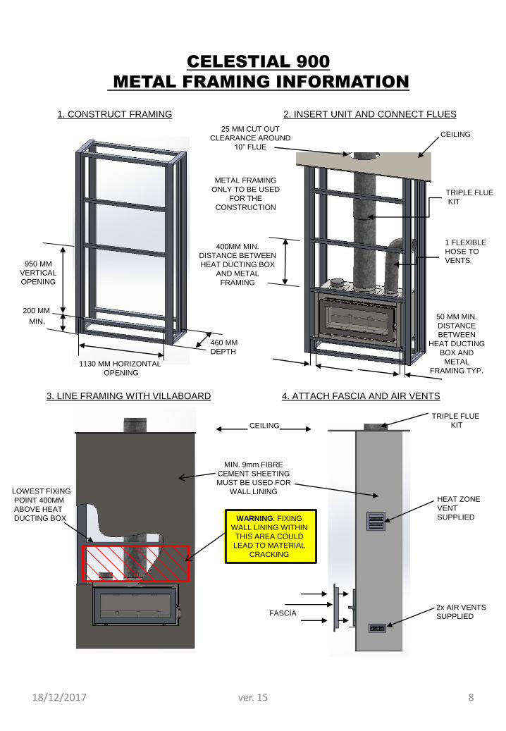
2x AIR VENTS
SUPPLIED
MIN. 9mm FIBRE
CEMENT SHEETING
MUST BE USED FOR
WALL LINING
200 MM
MIN.
TRIPLE FLUE
KIT
1130 MM HORIZONTAL
OPENING
CELESTIAL 900
METAL FRAMING INFORMATION
950 MM
VERTICAL
OPENING
1. CONSTRUCT FRAMING 2. INSERT UNIT AND CONNECT FLUES
3. LINE FRAMING WITH VILLABOARD 4. ATTACH FASCIA AND AIR VENTS
FASCIA
1 FLEXIBLE
HOSE TO
VENTS
METAL FRAMING
ONLY TO BE USED
FOR THE
CONSTRUCTION
460 MM
DEPTH
25 MM CUT OUT
CLEARANCE AROUND
10” FLUE
CEILING
CEILING
TRIPLE FLUE
KIT
50 MM MIN.
DISTANCE
BETWEEN
HEAT DUCTING
BOX AND
METAL
FRAMING TYP.
HEAT ZONE
VENT
SUPPLIED
400MM MIN.
DISTANCE BETWEEN
HEAT DUCTING BOX
AND METAL
FRAMING
LOWEST FIXING
POINT 400MM
ABOVE HEAT
DUCTING BOX WARNING: FIXING
WALL LINING WITHIN
THIS AREA COULD
LEAD TO MATERIAL
CRACKING
18/12/2017 ver. 15 8

CELESTIAL 900 MASONRY
BLOCK CONSTRUCTION
C
DETAIL C
100MM
FLAT TRIM
LINTEL
HEBEL BLOCKS HEAT DUCTINGBOX
STD.
FASCIA
18/12/2017 ver. 159
25mm min. air gap
Register plate with vented upstands
Minimum 600mm below ceiling.
Insul wool (supplied by installer) can
be placed on top of register plate
1 row of Hebel or brick to be used above
register plate before timber frame work is used
Ceiling
Triple skin flue system
(10”, 8” and 6”)
Stainless steel flue pipe.
All flue pipes must be
connected with pop rivets
supplied by installer
Rear of unit to
Hebel Block – 25mm min.
Hebel Block –
min. thickness – 75mm
25mm min. clearance between
10” flue and framing
6” Flue
Inlet air vents into chase
Rear timber stud wall
(combustible wall)
25mm min. air gap
Outlet air vents from chase
DETAIL A
All 8”-10” assembled flues must
have the crimps pointing upwards
crimped
plain
All 6” assembled flues must have
the crimps pointing downwards
crimped
plain
DETAIL B
B
A
Flue system to be installed
to suit AS/NZS 2918.2001
9mm Fibre
cement sheet

1180 M
IN
1080 M
IN
200 M
IN
800 M
IN T
O C
OM
BU
ST
IBLE
MA
TE
RIA
L
1000 M
IN
FLASHING
25 MM MIN
CLEARANCE25 MM MIN
CLEARANCE
BETWEEN 10” FLUE AND
FRAMING
25 MM MIN
CLEARANCE
BETWEEN BACK OF
UNIT AND FIBRE
CEMENT WALL /
BRICKS
METAL
CONSTRUCTION
MIN. 9mm FIBRE
CEMENT
SHEETING
FASCIA
FASCIA
VILLABOARD
HEAT DUCTING
BOX
18 MM BELLIS BOARD
OR EQUIVALENT
FOR WOODEN
FLOORS
725 670
DETAIL A
A
METAL FRAMING
OR REFRACTORY
10”
8”
6”
IF COWL IS LESS THAN 3000 MM
TO RIDGE LINE, COWL TO BE
600 MM ABOVE RIDGE
CELESTIAL 900
INFORMATION FOR TYPICAL
METAL FRAME
A
DOOR
SIDE VIEW
MANTLE
CEILING
METAL
FRAME
FIRE
BOX
(REFER HEARTH
MEASUREMENT
DRAWING IF UNIT IS
HIGHER THAN 200 MM FROM FLOOR.)
18/12/2017 ver. 15 10

CELESTIAL 900 INFORMATION
25 MM MIN CLEARANCE
AROUND 10” FLUE
DETAIL B
SUPPORT OUTER FLUE
WITH ANGLE BRACKET
SUPPLIED
ROOF FLASHING
SUPPLIED BYCONTRACTOR
ALL CASING FLUE PIPES
MUST BE CONNECTED
VIA POP RIVETS SUPPLIED
BY INSTALLER
STAINLESS STEEL
FLUE PIPE. ALL FLUE
PIPES MUST BE
CONNECTED WITH
POP RIVETS
SUPPLIED BY
INSTALLER
STAINLESS STEEL DOUBLE
CONE COWL
DISTANCE ABOVE ROOF LINE
OR 600 MINIMUM ABOVE
RIDGE IF PENETRATION IS 3
METRES OR CLOSER TO
RIDGE
POP RIVET OR SCREW
BRACKETS TO THE OUTSIDE
OF THE OUTER CASING
SHORT TUBE FROM THE
COWL FITS INTO FLUE PIPE.
ALL FLUES SHOULD BE
TRIMMED LEVEL
B
A
DETAIL A
6” FLUE
8” FLUE
10” FLUE
FLEXIBLE
HOSE FOR
HEAT ZONE
VENT
FRONT VIEW
DETAIL c
ALL 8”-10” ASSEMBLED FLUES
MUST HAVE THE CRIMPS
POINTING UPWARDS
ALL 6” ASSEMBLED FLUES
MUST HAVE THE CRIMPS
POINTING DOWNWARDS
CRIMPED
PLAIN
DETAIL DDETAIL C
CRIMPED
PLAIN
RUN A BEAD OF SILICONE DOWN
THE VERTICAL SEAM OF THE OUTER
CASING TO THE FLASHING
C-D
18/12/2017 ver. 1511

3000 OR LESS
INSTALLATION INSTRUCTIONSMINIMUM HEIGHT OF FLUE SYSTEM EXIT
INSTALLATION TO COMPLY WITH AS/NZS 2918
INCREASE FROM 1000 MIN
UNTIL CLEAR WITHIN 3000 OF
TOP OF FLUE
3000
ANY NEARBY
STRUCTURE
3000MORE THAN 3000
600 MIN 3000
1000 MIN IF CLEAR WITHIN
3000 OF TOP OF FLUE
INCREASE AS NECESSARY UNTIL
NOTHING WITHIN 3000 OF FLUE TOP
600 MIN
3000 OR LESS
18/12/2017 ver. 15 12
ABOUT CURING
Your stove has been painted with the highest quality silicone stove paint and has special break-in
procedures to cure it with heat and make it hard.
VENTILATE WELL
Ventilate the house during the first three times the stove is used. The paint on the stove will give off smoke
heavy with carbon dioxide and has an odor. Without adequate ventilation, concentrations of smoke could
irritate, or be upsetting, so open doors and windows and use a fan if necessary. After these initial burns the
paint will be cured and there should be no more smoke.
DON’T TOUCH DURING CURING
Don’t touch the surface. It will be soft and gummy during this paint curing phase. Once cured, it will not be
soft again.
CURE WITH 3 FIRES
Most stoves cure with 3 burns. The first two (2) should be 250°F for 20 minutes, or about half a normal fire.
Let the stove cool down between burns. The last fire should be 500°F to 700°F for at least 45 minutes. The
point being, cure slowly without a hot fire.
Stoves with cooler surface temperature and those that have been painted with another colour before, will
take longer to cure.
Curing can usually be observed by the effect of the paint turning flat as the heat radiates out from hotter
parts of the stove.
So remember...
•Ventilate well
•Do not touch during curing
•Cure with 3 fires
•Call your dealer for any questions
18/12/2017 ver. 15 13
INSTRUCTIONS FOR OPERATING YOUR
KEMLAN SLOW COMBUSTION WOOD
BURNING HEATER
1. Open the air inlet fully by sliding the air inlet control to high.
2. Crumple at least three double pages of newspaper into loose balls and place them into the centre of the
firebox.
Cross lay at least 15 to 20 pieces of kindling on top of the paper – if pine is used, the size should vary from
the thickness of a pencil to that of a knife handle – if hardwood is used split it even smaller.
3. Light the paper and close the door.
Once the kindling is well alight, add a few pieces of slightly larger hardwood, split to approximately 25mm x
50mm (2” x 1”).
4. Close the door and leave the air inlet control on high. When the hardwood is well alight (usually 5
to10minutes) and coals are starting to form, larger pieces of hardwood may be added – five or six pieces the
equivalent of 50mm x 50mm (2” x 2”) is ideal.
The object is to create a fiercely burning fire of reasonable small hardwood, which will quickly produce a
good bed of glowing coals on the floor of the firebox. This will take from 20 to 40 minutes depending on the
quality of the firewood.
5 Larger pieces of hardwood may now be added. Half fill the firebox and leave the air inlet control on high until
the wood is well alight then close the control approximately a third of its travel.
Usually about one hour after lighting, the air inlet control can be further shut down to achieve the desired
heat output.
When adding new firewood it is desirable to fully open the air inlet for approximately 10 to 15 minutes until
the new pieces are burning well, then it may be returned to its desired setting.
6. To set the fire for overnight burn – two-thirds fill the firebox with hardwood and fully open the air inlet.
Once the fire is burning well, the air inlet control should be shut down approximately three-quarters of its
travel. Setting the air inlet control may be varied to suit your particular requirements and the quality and size
of your firewood.
Remember wet or green wood may cause a dramatic reduction in the heat output of your heater (refer to
“Operating Hints” for more details).
7. Have the flue inspected at least once every 12 months as it may require cleaning.
8. Clean out excess ash from the floor of the firebox when required. Do not remove all the ash and in particular
leave any pieces of charcoal in the heater as they are good fuel.
9. If the glass door in your heater becomes dirty, your firewood is either green, wet or both. You may be
closing the air inlet down too soon after lighting or after adding new firewood.
To clean the glass, simply use some of the white ash in the firebox. Apply it with a damp cloth in a circular
motion. Remove residue with a clean cloth or paper. Do not clean the glass when the heater is operating.
10. To clean the painted surface, simply dust with a soft duster and wipe over with a damp cotton cloth. Only
clean when the heater is cool.
IMPORTANT:
UNDER NO CIRCUMSTANCES SHOULD ANY SOLVENTS SUCH AS METHYLATED SPIRITS, PETROL, MINERAL
TURPENTINE ETC BE ALLOWED TO COME IN CONTACT WITH THE PAINTED SURFACE OF THE HEATER AS
DAMAGE TO THE FINISH WILL RESULT. IF AN ACCIDENT DOES OCCUR, SPRAY CAN PAINT IS AVAILABLE FROM
YOUR NEAREST KEMLAN DEALER.
18/12/2017 ver. 1514

18/12/2017 ver. 1515

OPERATING HINTSTo get the best from your Kemlan heater it is essential that you use good firewood, and use it correctly Many people do not understand the
principle of using a wood burning appliance and we suggest that it will be worth your while to study the following extract from a well known
American publication.
PRINCIPLES OF COMBUSTION: HOW WOOD BURNS
Technically, wood does not burn. What burns is the volatiles and charcoal that are created. That is why wood will not catch on fire
immediately when you put a match to it; it has to first undergo the chemical changes that create the volatiles, and a match does not create
enough heat to activate the process. As kindling and paper evaporate the moisture in the wood, the wood absorbs heat. At a certain point,
gases are given off and when these volatiles reach 480 degrees F, or the “Flash point”, as it is called, they will burst into flame if sufficient
oxygen is present. The volatiles give off more heat than does charcoal, which is why a fire with flames (which burn the volatiles) produces
more heat than one that is all charcoal.
Since the volatiles are gases and since heat rises, taking the gases with it, it is very easy to create a situation in which most of the volatiles go
up the chimney almost as soon as they are produced. This is what happens with a roaring fire and, to a lesser extent, with an open fire. One of
the reasons (but only one) that a freestanding wood stove produces more heat than an open fire is that the volatiles are contained within the
firebox and are not so quickly dissipated up the chimney. A stove that is baffled is merely one that has interior construction design to keep the
volatiles in the firebox longer; the longer they are in the firebox, the more completely they burn. The more completely they burn, the more heat
is produced. It’s that simple.
Since the flames burn the volatiles and produce heat, the ideal situation is the longest possible flame path. As soon as wood burners
understand this, they tried to devise ways of making the flame path longer than in an ordinary open fire. Even though the role of oxygen in
combustion was not under- stood in Ben Franklin’s time, Franklin did realize the importance of more completely burned volatiles. His solution
was to try to invent a downdraft stove
– one that sent the volatiles back down through the fire – but he never succeeded in getting it to work. A downdraft goes against the nature of
volatiles, which is to rise. In more recent times, there have been some successful downdraft – or partial downdraft – stoves created and some
of the fireplace stoves and units utilise this principle. Ideally, it would be best if the volatiles could be redirected down through the fire several
times, until they were al- most totally consumed. This would not only make the maximum use of the heat potential of the wood; it would reduce
creosote build-up to almost zero. Perhaps someday an ingenious inventor will design a unit that does this; so far no has been able to.
MOISTURE AND COMBUSTION
As we have seen, dry wood ignites faster and burns better – with higher heat production – than wet or green wood. The difference between
the amount of heat produced by dry wood and green wood is so great that a dry softwood of good grade will produce more heat than green
hardwood. Green white ash, for instance, is not as good a fuel as dry tamarack.
The reason for the superiority of dry wood is easy to understand. Heat cannot be produced until moisture has been driven off. Since even so-
called seasoned dry wood contains approximately 20 percent moisture, it takes time for any fire to begin producing useable heat. Wet wood,
which can have a moisture content of over 100 percent (due to the way moisture is measured), will take that much longer to produce heat.
Meanwhile, the fire will produce smoke and creosote and very little heat. This was brought sharply to my attention when I installed my first
wood heater. To my surprise and delight, I found it comfortably heated eight rooms, where I had expected to heat only two or three. After
some time, when I had someone helping me run the fire, I suddenly noticed that the house was chilly. We added more wood and adjusted the
draft controls, but nothing we did seemed to help. It finally occurred to me to check the woodpile. My friend had been getting green wood from
a stack that was drying, instead of from the dry-wood stack. The difference the green wood made was so dramatic I will never forget it.
HOW TO TEST WOOD FOR DRYNESS
There are two easy ways for even a novice to spot dry wood. Dry wood tends to “check”. Look at the log ends and you will see cracks radiating
from the centre of the log. If the logs have been split, the cracks will be harder to find because wood tends to split along the cracks.
Another test for dry wood is the sound it makes when two logs are banged against each other. Green wood will make sort of a dull thud; dry
wood makes a nice crisp, sharp sound. Once you have heard the two, you will remember the difference.
FROM THE ABOVE EXTRACT SEVERAL FACTS BECOME APPARENT:
1. It is vital that your firewood be dry and seasoned.
2. A good hot fire of kindling and smaller pieces of fuel must be established before adding larger logs.
3. The larger logs should be well alight before slowing down the combustion by adjusting the air intake.
4. A hot bed of coals needs to be maintained to ensure continued combustion in the firebox.
5. When new timber is added to the firebox the air control should be opened until the fuel is well alight before damping it down again. This will
take from 10 to 20 minutes.
6. When setting the controls for overnight burn you will need to experiment with the settings to suit your particular type of fuel. Very dense
hardwood requires more air to combust and over damping will result in charring and smoking causing the glass in the door to become dirty.
The same will apply with fuel which is not fully seasoned or is not dry enough. Kemlan have followed a policy since 1969 of checking on all
complaints about poor performance of their heaters and apart from a few instances of incorrect installation (mostly insufficient flue length) all
problems have been directly related to incorrect operation and/or poor fuel. We know you will experience many years of satisfaction from your
heater if you follow the above advice.
18/12/2017 ver. 15 16

18/12/2017 ver. 15 17
WARRANTY
1. Kemlan wood heaters carry a warranty on the 6mm firebox for a period of ten (10) years.
2. This warranty also covers other components of the heater for a period of one (1) year. These
components include the baffle plate, handle assembly, secondary air tubes and fan.
3. Kemlan’s warranty covers the wood heaters against defects in materials and manufacture.
4. THIS WARRANTY DOES NOT COVER –
4.1 Failure to comply with manufacturer’s operation instructions.
4.2 Normal wear and tear or damage caused by incorrect installation.
4.3 Any form of rust and/or corrosion to the painted finish of the heater.
4.4 Damage to the glass in the door, if the damage is caused by impact or misuse.
4.5 The cost of collection and delivery of the wood heater and/or parts.
4.6 Damage caused by water ingress.
4.7 Cost of removal of defective heater or re-installation of replacement heater.
4.8 Failure to use fireplace components supplied by Kemlan Industries Pty Ltd.
4.9 Cost of inspection for damaged heater.
5. CLAIMS –
5.1 (I) Kemlan will provide a full replacement of the heater in the first five years after installation.
(ii) Replacement in the subsequent five years (i.e. sixth to tenth year after installation will be on the
following basis.
Owner will pay fifty percent of the current retail price, if the claim is made in the sixth year – tenth year
after purchase.
5.2 Replacement of heater subject to all conditions in section four of warranty.
5.3 Should any defects occur, contact the Kemlan distributor from whom you purchased the heater.
5.4 Under this warranty the defective parts will be repaired or replaced, free of charge.
6. The fireplace installation must comply with the relevant local statutes, ordinances, regulations and by-
laws.
PLEASE COMPLETE AND RETAIN THIS SECTION FOR YOUR
RECORDSPurchased from: .......................................................................................................
Address: ....................................................................................................................
Date of Purchase: ......................................................................................................

18/12/2017 ver. 15
NOTES
18

18/12/2017 ver. 15 19

18/12/2017 ver. 15 20