INSTALLATION, OPERATING AND SERVICE INSTRUCTIONS …s3.supplyhouse.com/product_files/Burnham -...
47
8142711R24-7/99 Price - $3.00 INSTALLATION, OPERATING AND SERVICE INSTRUCTIONS FOR V7 SERIES OIL FIRED BOILER KNOCKDOWN & PACKAGED HEATING UNITS The ULC label or listed marking on a product is the only evidence provided by Underwriters' Laboratories of Canada to identify products which have been produced under the listing and follow-up service. These instructions have been reviewed by ULC and found suitable for use in the installation of ULC labeled V-7 Series Boilers. As an ENERGY STAR ® Partner, Burnham Corporation has determined that the V73WR (0.60 GPH), V74WR (0.80 GPH), V75WR (0.90 GPH), and V76WR (1.15 GPH) meet the ENERGY STAR ® guidelines for Energy efficiency established by the United States Environmental Protection Agency (EPA). For service or repairs to boiler, call your heating contractor. When seeking information on boiler, provide Boiler Model Number and Serial Number as shown on Rating Label. Boiler Model Number Boiler Serial Number Installation Date _V7 ____-____ 6_ _ _ _ _ _ _ Heating Contractor Phone Number Address
Transcript of INSTALLATION, OPERATING AND SERVICE INSTRUCTIONS …s3.supplyhouse.com/product_files/Burnham -...

18142711R24-7/99
Price - $3.00
INSTALLATION,OPERATING AND SERVICE
INSTRUCTIONS FORV7 SERIES OIL FIRED BOILERKNOCKDOWN & PACKAGED
HEATING UNITS
The ULC label or listedmarking on a product is theonly evidence provided byUnderwriters' Laboratories ofCanada to identify productswhich have been producedunder the listing and follow-upservice.
These instructions have beenreviewed by ULC and foundsuitable for use in theinstallation of ULC labeledV-7 Series Boilers.
As anENERGYSTAR® Partner,Burnham Corporationhas determined that theV73WR (0.60 GPH),V74WR (0.80 GPH),V75WR (0.90 GPH),and V76WR (1.15 GPH)meet the ENERGY STAR®
guidelines for Energyefficiency established by theUnited States EnvironmentalProtection Agency (EPA).
For service or repairs to boiler, call your heating contractor. When seeking information on boiler, provideBoiler Model Number and Serial Number as shown on Rating Label.
Boiler Model Number Boiler Serial Number Installation Date
_V7 ____-____ 6_ _ _ _ _ _ _ Heating Contractor Phone Number
Address

2
IMPORTANT INFORMATION - PLEASE READ THIS PAGE CAREFULLY1. THIS BOILER HAS LIMITED WARRANTIES, COPIES OF WHICH ARE PRINTED ON THE BACK COVER OF THIS
MANUAL.2. THIS BOILER IS SUITABLE FOR INSTALLATION ON COMBUSTIBLE FLOORING. BOILER CANNOT BE IN-
STALLED ON CARPETING.3. ALL BOILERS MUST BE INSTALLED IN ACCORDANCE WITH NATIONAL, STATE AND LOCAL PLUMBING,
HEATING AND ELECTRICAL CODES AND THE REGULATIONS OF THE SERVING UTILITIES WHICH MAYDIFFER FROM THIS MANUAL. AUTHORITIES HAVING JURISDICTION SHOULD BE CONSULTED BEFOREINSTALLATIONS ARE MADE.IN ALL CASES, REFERENCE SHOULD BE MADE TO THE FOLLOWING STANDARDS:
USA BOILERSA. Current Edition of American National Standard ANSI/NFPA 31, “Installation of Oil Burning Equipment”, for clearances between boiler, vent connector and
combustible material.B. Current Edition of American National Standard ANSI/NFPA 211, “Chimneys, Fireplaces, Vents, and Solid Fuel Burning Appliances”, For Chimney require-
ments, type of venting material and clearances between vent connector pipe and combustible materials.C. Current Edition of American Society of Mechanical Engineers ASME CSD-1, “Controls and Safety Devices for Automatically Fired Boilers”, for assembly and
operations of controls and safety devices.CANADA BOILERS
A. Current Edition of Canadian Standards Association CSA B139, “Installation Code for Oil Burning Equipment”, for recommended Installation Practices.
4. ALL HEATING SYSTEMS SHOULD BE DESIGNED BY COMPETENT CONTRACTORS AND ONLY PERSONSKNOWLEDGEABLE IN THE LAYOUT AND INSTALLATION OF HYDRONIC HEATING SYSTEMS SHOULDATTEMPT INSTALLATION OF ANY BOILER.
5. THE BOILER MUST BE CONNECTED TO AN APPROVED CHIMNEY IN GOOD CONDITION. SERIOUS PROPERTYDAMAGE COULD RESULT IF THE BOILER IS CONNECTED TO A DIRTY OR INADEQUATE CHIMNEY. THEINTERIOR OF THE CHIMNEY FLUE MUST BE INSPECTED AND CLEANED BEFORE THE START OF THE HEAT-ING SEASON AND SHOULD BE INSPECTED PERIODICALLY THROUGHOUT THE HEATING SEASON FOR ANYOBSTRUCTIONS. A CLEAN AND UNOBSTRUCTED CHIMNEY FLUE IS NECESSARY TO ALLOW NOXIOUSFUMES THAT COULD CAUSE INJURY OR LOSS OF LIFE TO VENT SAFELY AND WILL CONTRIBUTE TOWARDMAINTAINING THE BOILER’S EFFICIENCY.
6. READ THE LITERATURE ENCLOSED BY THE MANUFACTURER WITH THE VARIOUS ACCESSORY DEVICES.THESE ACCESSORY DEVICES MUST BE INSTALLED AND USED ACCORDING TO THE RECOMMENDATIONSOF THE MANUFACTURER.
7. IT IS THE RESPONSIBILITY OF THE INSTALLING CONTRACTOR TO SEE THAT ALL CONTROLS ARE COR-RECTLY INSTALLED AND ARE OPERATING PROPERLY WHEN THE INSTALLATION IS COMPLETED.
8. FOR OPTIMUM PERFORMANCE AND SERVICEABILITY FROM THIS BOILER ADHERE TO THE FOLLOWINGRECOMMENDATIONS:
A. DO NOT TAMPER WITH THE BOILER OR CONTROLS. Retain your contractor or a competent serviceman to assure that the boiler is properly adjusted andmaintained.
B. Clean flueways at least once a year - preferably at the end of the heating season to remove soot and scale. Inside of firebox should also be cleaned at the sametime.
C. Have oil burner and controls checked at least once a year or as may be necessitated.
WARNING
High water temperatures increase the risk of burns or scalding injury. Install an automatic tempering(mixing) valve at the tankless heater outlet to avoid excessively hot water at the fixtures.
WARNING
All boilers equipped with burner swing door have a potential hazard which can cause severe propertydamage, personal injury or loss of life if ignored. Before opening swing door, turn off service switch toboiler to prevent accidental firing of burner outside the combustion chamber. Be sure to tighten swing doorfastener completely when service is completed.
WARNING
This boiler is designed to burn No. 2 fuel oil only. Do not use gasoline, crankcase drainings, or any oilcontaining gasoline. Never burn garbage or paper in this boiler. Do not convert to any solid fuel (i.e.wood, coal) or gaseous fuel (i.e. natural gas, LP/propane). All flammable debris, rags, paper, wood scraps,etc., should be kept clear of the boiler at all times. Keep the boiler area clean and free of fire hazards.

3
TABLE OF CONTENTSI. General Information ............................. 3
II. Knockdown Boiler Assembly ............... 7III. Installation Instructions ...................... 12
IV. Operating Instructions ........................ 21V. Boiler Cleaning .................................. 29
VI. Repair Parts ........................................ 31Burner Specifications ......................... 46
SECTION I: GENERAL INFORMATION
Figure 1A: V72 thru V79 Water Boiler Without Tankless Heater (WB)
TABLE 1: DIMENSIONAL DATA (SEE FIGURES 1A THRU 1E)
IMPORTANT
Before starting to install this oil boiler, read these instructions carefully. Keep instructions in legible condition andposted near oil boiler for reference by owner and service technician.
BoilerModel
No.
DimensionsMinimum
Chimney Size
Water Content -Gallons
Heat TransferSurface Area -
Sq. Ft.Approximate
Shipping Weight(LB.)
"A" "B" "C"SteamBoiler
WaterBoiler
Steam Boiler
V72 11-3/8" 6-3/8" 5" 8" x 8" x 15' ---- 10.6 ---- 381
V713 16" 8-3/4" 6" 8" x 8" x 15' ---- 13.5 ---- 524
V73 15-3/8" 8-3/8" 6" 8" x 8" x 15' 10.8 13.2 13.8 478
V714 20" 10-3/4" 6" 8" x 8" x 15' ---- 15.9 ---- 580
V74 19-3/8" 10-3/8" 6" 8" x 8" x 15' 13.5 15.9 19.7 575
V75 23-3/8" 12-3/8" 7" 8" x 8" x 15' 16.1 18.5 25.6 674
V76 27-3/8" 14-3/8" 7" 8" x 8" x 15' 18.6 21 31.4 773
V77 31-3/8" 16-3/8" 8" 8" x 12" x 15' 21.2 23.6 37.3 872
V78 35-3/8" 18-3/8" 8" 8" x 12" x 15' 23.8 26.2 43.1 971
V79 39-3/8" 20-3/8" 8" 8" x 12" x 15' 26.4 28.8 49.0 1070
NOTE: 1. Maximum Working Pressure 15 PSI (Steam) and 30 PSI (Water)2. The V72, V713 and V714 Boilers are available as packaged water boilers only3. The V713 and V714 are not ULC listed Models

4
Figure 1B: V73 thru V79 Water Boiler with Tankless Heater (WBT)
Figure 1C: V73 thru V79 Steam Boiler with or without Tankless Heater ("SBT" or "SB")

5Figure 1E: V713 and V714 Packaged Water Boiler with Tankless Heater (WBT)
Figure 1D: V713 and V714 Packaged Water Boiler Less Tankless Heater (WB)
Βυρνηαµ
Burnham
6
TABLE 2: Minimum Installation Clearances ToCombustible Materials (Inches)
A. INSPECT SHIPMENT carefully for any signs ofdamage.
1. ALL EQUIPMENT is carefully manufactured,inspected and packed. Our responsibility ceasesupon delivery of crated boiler to the carrier in goodcondition.
2. ANY CLAIMS for damage or shortage in shipmentmust be filed immediately against the carrier by theconsignee. No claims for variances from, orshortage in orders, will be allowed by themanufacturer unless presented within sixty (60)days after receipt of goods.
B. LOCATE BOILER in front of final position beforeremoving crate. See Figures 1A thru 1E.
1. LOCATE so that smoke pipe connection tochimney will be short and direct. BOILER ISSUITABLE FOR INSTALLATION ONCOMBUSTIBLE FLOOR. Boiler cannot beinstalled on carpeting.
2. FOR BASEMENT INSTALLATION, provide asolid base, such as concrete, if floor is not level, orif water may be encountered on floor around boiler.
3. PROVIDE SERVICE CLEARANCE of at least 24”on right side of boiler for removal of rear tanklessheater. Provide at least 24” clearance from frontjacket panel for servicing and removal of fronttankless heater (increase to 30" for #A54 heater).Provide at least 24" clearance from right side ofboiler or top of boiler for cleaning flueways. Boilerflueways may be cleaned either from the top orfrom the side.
4. For minimum clearances to combustible materials.See Table 2.
C. PROVIDE AIR SUPPLY AND VENTILATION toaccommodate proper combustion. If natural ventilationis inadequate, provide a screened opening or duct fromthe boiler room to the outside. The opening or ductmust be sized so the boiler input will not exceed 4,000BTUH/Sq. In. of free area. If other air consumingappliances are near the boiler, the air inlet should belarger. Consult respective manufacturers.
BoilerA
AboveB
Front
CChimney
ConnectorD
RearE
Sides
V7 6 24 18 6 6
NOTE 1: Listed clearances comply with AmericanNational Standard ANSI/NFPA 31, Installation of OilBurning Equipment.
NOTE 2: V7 Series boilers can be installed in roomswith clearances from combustible material as listedabove. Listed clearances cannot be reduced foralcove or closet installations.
NOTE 3: For reduced clearances to combustiblematerial, protection must be provided as described inthe above ANSI/NFPA 31 standard.

7
SECTION II: KNOCKDOWN BOILER ASSEMBLY
A. REMOVAL OF BARE BOILER FROM SKID
1. Boiler is secured to base with 4 bolts, 2 on front and2 on rear, see Figure 2. Remove all bolts.
2. Tilt boiler to right and to rear. Using right rear legas pivot, rotate boiler 90° in a clockwise direction,and lower left side of boiler to floor. Tilt boiler andremove crate skid.
Note: If Boiler is Packaged Go To Section III
Figure 2
B. MOVE BOILER TO PERMANENT POSITION bysliding or walking.
C. TEST BOILER FOR LEAKS before installingcontrols, trim, and jacket, and before connecting toheating system.
1. Loosen nuts on tie rods until only finger tight.
2. Install pressure gauge (at least 30 P.S.I. capacity), ahose to the city water and a valve in the supplytapping. Plug remainder of tappings.
3. Fill boiler with water and apply a pressure of atleast 10 pounds but no more than 30 pounds gaugepressure.
4. Examine Boiler carefully inside and outside forleaks or damage due to shipment or handling.
D. DRAIN WATER FROM BOILER. Remove gauge,valve and plugs from those tappings to be used. Leaveother tappings plugged or bushed according to Figure4.
E. INSPECT JOINTS BETWEEN SECTIONS. All jointsare factory sealed. If there are any spaces due toshipment or handling, seal them with boiler putty.
F. INSPECT FLUE COVER PLATES for tightness. Ifloose, retighten mounting hardware. If flue plate orsealing insulation is damaged repair or replace asneeded.
G. INSTALL AND SECURE CANOPY with cerafeltgasket and hardware provided to ensure gas tight seal— see Figure 3.
1. Cut two (2) strips 13 ¾” lg. from the roll of cerafeltgasket insulation. Place one (1) strip across the topof the front section and the other across the rear
section as shown in Fig. 3. Place gaskets so as notto allow any flueway blockage.
2. Cut the remainder of the roll into two (2) equalpieces. Place each piece along the sides, allowingthe ends to overlap the front and rear pieces.
Do not allow any flueway blockage.
3. Position canopy body within the retaining barwhich borders the flueway openings on top of thebare boiler block assembly.
IMPORTANT: Jacket support bracket must befacing left side of boiler — see Figure 3.
4. Secure canopy to boiler with two (2) 1/4" - 20 x 3"lg. carriage bolts, 1/4" flat washers and 1/4" - 20wing nuts provided.
H. INSTALL the following steam or water trim thatwould be concealed or inaccessible after flush jacket isinstalled, see Figure 4 for boiler tapping locations andusage.
1. STEAM BOILER — Top tappings:
a. Tapping "L" — Install 2" plug in rear sectiontop supply tapping on boiler sizes V73 thruV75.
b. Tapping “M” — Install ¾” coupling and ¾” x8” long nipple into ¾” tapping located next tofront section top supply tapping — all boilersizes.
2. WATER BOILER — Top tappings:
a. Tapping “L” — Install 2” plug in rear sectiontop supply tapping on boiler sizes V73 thruV79.
Figure 3

8
Figure 4: Boiler Tapping Locations and Usage (Knockdown Boilers Only)
PU R P O SE O F TA PP IN G S
Tapp ingLoca tion
S ize S team B o ile r W a te r B o ile r
Non -Hea ter w /Hea te r Non -Hea ter F ron t Hea te r R ear Hea ter
A ¾ "PA 4 04A P res su retro l (P robe LW CO )
P lugg ed (F lo at LW CO )L 81 48A
Op era tin g C on trolL81 24 C
Op era tin g C on trolF lush Plu g
B ¼ " P re ss ure /Va cu um G aug e Tem p era tu re/P re ss ure G aug e
C ¾ "P ro be LW C O Std.
P lugg ed (F lo at LW CO )F lush Plu g
C-C ¾ " F lush Plu g F lush Plu g F lush Plu g
D ½ "W ater Gau ge G las s (P robe LW CO )
W ater G aug e G lass , P re ss uretrol, a nd LW CO (Flo at)F lush Plu g
F ¾ " -- -- -L4 006 A Op era tin g
C on trol-- -- - Dis re gard
L81 24 COp era tin g C on trol
G 1½ " B us he d to ¾ " for Drainc oc k (O pt iona l Re tu rn ) R eturn
H 1½ " R eturn B us he d to ¾ " for Drainc oc k (O pt iona l Re tu rn )
J 1½ " S u rfac e B low off - Plu gge d F lush Plu g
K 2" Fron t Su pply (3 th ru 9 Se ction ) Fron t Su pply (3 th ru 9 Se ction )
L 2"P lug ged , Opt ion al S e co nd Su pply (3 th ru 5 Se ction )
R eq uire d S e co nd Su pply (6 th ru 9 Se ction )Plu gge d (3 th ru 9 Se ction )
M ¾ " S afety Valv e Re lie f Valv e
P ¾ " Au xilia ry Tapp ing - Plu gge dA ux . Ta pp in g -
Plu gge dDis re gard
A ux . Ta pp in g -Plu gge d
R ¾ " Au xilia ry Tapp ing - Plu gge d Au xilia ry Tapp ing - Plu gge d

9
Figure 5: Knockdown Boiler Jacket Assembly
b. Tapping “M” —Install ¾” x 8” long nipple into¾” tapping located next to front section topsupply tapping — all boiler sizes.
I. INSTALL FLUSH JACKET (See Figure 5).
1. Remove burner swing door mounting plate. Loosenthe bottom bolt three full turns. Remove (5)remaining 5/16” bolts securing mounting plate toboiler sections.
Lift up and remove plate.
2. Install rear jacket panel. Align two dimpled holeson jacket panel with the cast iron lugs. Secure withtwo #10 x 3/8” long self tapping screws.
3. JACKET FRONT PANEL
a. Install black plastic collar extension to jacketfront panels with 7-13/16" dia. heater opening.Engage two (2) retaining tabs over raw edge ofopening. Provide support behind the panel withone hand while applying pressure on collar tosnap each tab over edge of opening until alleight (8) tabs are securing collar.
b. Install front jacket panel. Locate two 3/16”diameter holes on front panel approximately 16”up from the bottom of the panel and 4½” infrom each side. Align these holes with thesimilarly located cast iron lugs on the frontsection. Secure with two #10 x 3/8” long self-tapping screws.
4. Install jacket left side panel. Fold panel atperforation keeping insulation inward. Align left
side panel mounting holes with the front and rearpanel holes. Secure with #8 x ½” long sheet metalscrews.
5. Install jacket top panel. Place jacket top panel onboiler and secure to front, rear and left side panelswith #8 x ½” long sheet metal screws.
6. Install jacket lower right side panel. Align rightside panel mounting holes with front and rear panelholes. Secure with #8 x ½” long sheet metal screws.
7. Install jacket upper right side access panel. Usingthe thumb holes, hold access panel 1” above lowerright side panel. Engage flanges on access panelwith surrounding panels and lower into positionuntil access panel is resting flush with top paneland bottom flange is properly locked into positionwith lower right side panel.
8. Attach the data labels shipped in the instructionenvelope as follows: (see Figure 5).
a. Place the Rating Label (serialized)approximately 1/4" below the top edge and3-1/2" from the right edge of the jacket frontpanel as shown. Mark outline of label on jacketwith a pencil. Remove paper backing fromlabel, realign label with pencil marks and applylabel to jacket by using backing paper to rubacross face of label.
b. Locate the Combination Label (P/N 8142756)on the front right corner of top panel,approximately 3/8" from each edge as shown.Mark the location and apply label in the same

10
manner as rating label.
c. On steam boilers, install the Lowest PermissibleWater Level Plate, Form No. 1204 (shipped inSteam Trim Carton), on the jacket right sidepanel. Align the two holes in the plate with thetwo 1/8” dia. holes located near the front edge,in line with the lower sight glass tapping, andsecure with #8 x ½” lg. sheet metal screws.
J. INSTALL OIL BURNER (See Figure 6).
1. Check target wall and cerafelt blanket incombustion chamber. If any damage or movementoccurred during shipment, repair or replace asneeded.
2. Check the burner mounting plate and swing doorinsulation pieces for damage and adhesion. Ifdamaged, replace insulation. If loose, re-attach withRTV 732 or 736 silicone caulk.
3. Engage bottom slot on burner mounting plate withmatching bolt in bottom tapping of front section.Align mounting holes and fasten the mountingplate to the boiler sections with (5) five 5/16” boltsand washers removed in step 8a. Fully tighten allbolts.
4. Place burner flange gasket on burner swing doorand thread two 5/16” x ½” long bolts into verticalset of holes approximately three full turns.
5. Insert oil burner air tube into the opening of theburner swing door. Align keyhole slot with verticalset of bolts, engage hex head of bolts and rotate
burner to the left. Install two remaining 5/16” x ½”long bolts in horizontal sets of holes. Level burnerand fully tighten all bolts.
K. INSTALL STEAM BOILER TRIM AND CONTROLS(See Figures 1C & 4).
1. Thread the combination pressure/vacuum gaugeinto the ¼” tapping. Tighten with wrench appliedto the square shank of the gauge. Do not applypressure to the gauge case — this might destroy thecalibration of the gauge.
2. Thread 1½” x ¾” bushing and a ¾” drain cock intothe 1½” tapping located in the lower right corner ofthe front casting. Tighten with wrench.
NOTE: Lower rear section tapping “H” is used forstandard condensate return on steam boilers.
3. Thread safety relief valve, as shown in Figure 1C,into 3/4" coupling and 3/4” x 8” nipple previouslyinstalled in step H. Tighten with wrench.
NOTE: Pipe discharge as shown in Figure 8.
4. Install probe type LWCO if so equipped. Threadprobe into ¾” tapping located on the front sectiondirectly above the protectorelay on the oil burner.Read the manufacturer’s instructions packed withthe probe LWCO for proper pipe dope application.DO NOT use Teflon tape on probe threads. Use ofteflon can render the probe LWCO inoperational.Slip the LWCO control over the probe and clamp inplace. Connect the wire(s) between the probe andcontrol per the manufacturer’s instructions. Install
Figure 6
11
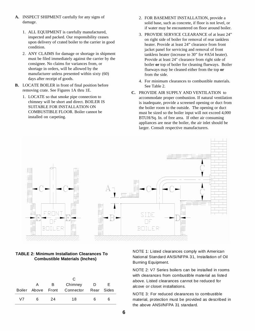
the sight glass using the two ½” tappings to theright of the probe LWCO.
5. Install float-type Low Water Cutoff, if so equipped.See Figure below.a. Install nipples and unions in Tappings D.b. Mount hardware to low water cutoff body. Install
assembly.c. Install water gage glass on low water cutoff
assembly's tee fittings.
6. Install Limit Control.a. Probe LWCO: Install Limit in Tapping A using
¾ NPT x 2" nipple, ¾ NPT elbow, ¾ NPT x ¼NPT bushing, and syphon. See Figure belowright.
b. Float LWCO: Remove ¼ NPT plug from top ofLow Water Cutoff. Install Syphon and Limit intothis tapping. See Figure below.
7. On units equipped with a tankless heater, install theaquastat controller well in the ¾” tapping in tanklessheater plate. Slip the bulb of the aquastat into the welland secure the control in place with the set screw.
8. Connect the field wiring to the pressure limit, theLWCO, the burner J-box, and from the aquastatcontrol (if equipped with tankless heater) to the oilburner primary control's "T-T" terminals. Make thewiring connections as shown in Figures 17 thru 20.
L. INSTALL WATER TRIM AND CONTROLS(See Figures 1B and 4).
1. Thread ½” pipe plugs into gauge glass tappings inthe upper right side of front section.
2. Thread ¾” pipe plug in probe low water cut offtapping (just left of gauge glass tappings).
3. Thread combination pressure/temperature gauge into¼” tapping. Tighten with wrench applied to thesquare shank of the gauge. Do not apply pressure tothe gauge case - this might destroy the calibration ofthe gauge.
4. Screw drain valve into 1½” tapping in lower rearsection using 1½” x ¾” bushing (note - lower frontsection tapping “G” (see Figure 4) is used forstandard return on water boilers).
5. If CIRCULATOR (not supplied with boiler) is to bemounted directly to 1½" boiler return tapping "G",use the piping arrangements outlined in steps a. thrue. as follows:
a. Thread 1½” x 3” long nipple and 1½” x 90°elbow into the return tapping and tighten with apipe wrench.
b. Thread 1½” NPT x 15” long pipe nipple into the90° elbow and tighten with a pipe wrench.
c. Thread one of the circulator flange onto the pipenipple and tighten with a pipe wrench. Positionflange so that the bolt slots are perpendicular tothe boiler front.
d. Place a flange gasket in the flange groove on thecirculator and mount the circulator on the flangeinstalled in step 3. Note that this is the returnpiping and the flow arrow on the circulator shouldpoint down �. Fasten circulator with 7/16” nutsand bolts.
e. Bolt second circulator flange and gasket to thecirculator with 7/16” nuts and bolts.
6. Install pressure relief valve, as shown in Figure 1B,onto ¾” x 8” nipple previously installed in Step H.Tighten with wrench.
NOTE: Pipe discharge as shown in Figure 9.
7. On units without a tankless heater, install the controlwell into the ¾” tapping located on the front of theboiler in the upper left corner. Tighten the well andinsert the control’s bulb into the well. Secure thecontrol with set screw on the control.
8. On units with a tankless heater, install the controlwell in the ¾” tapping on the tankless heater plate.Tighten the well and insert the control’s bulb into thewell. Secure the control with set screw on the control.
9. Connect the field wiring from the circulator to thecontrol and from the control to the burner J-Box.Make the wiring connections as shown on Figures 21and 22.
NOTE: Proceed to Installation Instructions SectionIII, step E, to continue.
Float-type Low Water Cutoff Installation Limit Installation for Probe LWCO EquippedBoilers

12
SECTION III: INSTALLATION INSTRUCTIONSA. REMOVE CRATE — (Packaged Boilers)
1. Remove all fasteners at crate skid.2. Lift outside container and remove all other inside
protective spacers and bracing. Remove draftregulator box and miscellaneous trim bagcontaining safety/relief valve, and pipe fittings.
B. REMOVAL OF BOILER FROM SKID
Fig. 71. Boiler is secured to base with 4 bolts, 2 on left side
and 2 on right side, see Figure 7. Remove all bolts.2. Tilt boiler to right and to rear. Using right rear leg
as pivot, rotate boiler 90° in a clockwise direction,and lower left side of boiler to floor. Tilt boiler andremove crate skid. Care should be exercised toprevent damage to jacket or burner.
C. MOVE BOILER TO PERMANENT POSITION bysliding or walking.
D. INSPECT COMBUSTION TARGET WALL ANDCOMBUSTION CHAMBER LINER
1. OPEN FLAME OBSERVATION DOOR AND/ORBURNER SWING DOOR on front of boiler. Useflashlight to inspect target wall secured to rearsection with silastic sealant. Inspect ceramic fiberblanket secured to floor of boiler with water glassadhesive. If either is damaged they must bereplaced.
E. CONNECT SUPPLY AND RETURN PIPING TOHEATING SYSTEM.
CLEARANCES — Steam and hot water pipes shallhave clearances of at least ½” from all combustibleconstruction.
1. With STEAM HEATING, see Figure 8. Consult I =B = R Installation and Piping Guide No. 200.
2. With Forced Circulation HOT WATER HEATING,see Figure 9. Consult I = B = R Installation andPiping Guide No. 200.
3. Packaged boilers. Install Safety Valve in TappingM. Use ¾ NPT x 8" nipple and ¾ NPT couplingincluded in trim bag. Safety Valve must beinstalled with spindle in vertical position.
TS-39-26-A
4. Packaged boilers with Probe style LWCO. InstallLimit in Tapping A using ¾ NPT x 2" nipple, ¾NPT elbow, ¾ NPT x ¼ NPT bushing, and syphonincluded in trim bag. See Figure on previous page.Connect wiring harness from Low Water Cutoff.See Figure below.
TS-39-126-A
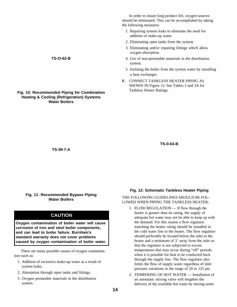
5. If this boiler is used in connection withrefrigeration systems, the boiler must be installed sothat the chilled medium is piped in parallel with theheating boiler using appropriate valves to preventthe chilled medium from entering the boiler, seeFigure 10. Also consult I = B = R Installation andPiping Guides.
6. If this boiler is connected to heating coils located inair handling units where they may be exposed torefrigerated air, the boiler piping must be equippedwith flow control valves to prevent gravitycirculation of boiler water during the operation ofthe cooling system.
7. Use a boiler bypass if the boiler is to be operated ina system which has a large volume or excessiveradiation where low boiler water temperatures maybe encountered (i.e. converted gravity circulationsystem, etc.).Remove the circulator and install a pipe teebetween the circulator and boiler return along witha second tee in the supply piping as shown inFigure 11. The bypass should be the same size asthe supply and return lines with valves located inthe bypass and supply outlet as illustrated in Figure11 in order to regulate water flow for maintenanceof higher boiler water temperature.Set the by-pass and boiler supply valves to a halfthrottle position to start. Operate boiler until thesystem water temperature reaches its normaloperating range.Adjust the valves to maintain 180°F boiler watertemperature. Adjust both valves simultaneously.Closing the boiler supply valve and opening the by-pass valve will raise the boiler water temperatureand lower the supply temperature. Opening theboiler supply valve while closing the by-pass valvewill lower the boiler water temperature and raisethe supply temperature.
8. A hot water boiler installed above radiation levelmust be provided with a low water cutoff device aspart of the installation.
13
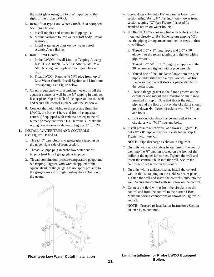
Fig 8: V73 Thru V79 Recommended Boiler Piping For Gravity Return Steam Boiler
Fig. 9: V72 thru V79, V713 and V714 Recommended Boiler Piping for Series Loop Forced Hot Water System
TS-39-17-D
TS-39-4-C
14
There are many possible causes of oxygen contamina-tion such as:
1. Addition of excessive make-up water as a result ofsystem leaks.
2. Absorption through open tanks and fittings.
3. Oxygen permeable materials in the distributionsystem.
CAUTION
Oxygen contamination of boiler water will causecorrosion of iron and steel boiler components,and can lead to boiler failure. Burnham'sstandard warranty does not cover problemscaused by oxygen contamination of boiler water.
Fig. 11: Recommended Bypass PipingWater Boilers
Fig. 10: Recommended Piping for CombinationHeating & Cooling (Refrigeration) Systems
Water Boilers
In order to insure long product life, oxygen sourcesshould be eliminated. This can be accomplished by takingthe following measures:
1. Repairing system leaks to eliminate the need foraddition of make-up water.
2. Eliminating open tanks from the system.
3. Eliminating and/or repairing fittings which allowoxygen absorption.
4. Use of non-permeable materials in the distributionsystem.
5. Isolating the boiler from the system water by installinga heat exchanger.
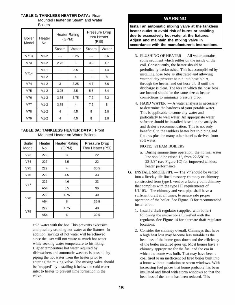
F. CONNECT TANKLESS HEATER PIPING ASSHOWN IN Figure 12. See Tables 3 and 3A forTankless Heater Ratings.
Fig. 12: Schematic Tankless Heater Piping
THE FOLLOWING GUIDELINES SHOULD BE FOL-LOWED WHEN PIPING THE TANKLESS HEATER:
1. FLOW REGULATION — If flow through theheater is greater than its rating, the supply ofadequate hot water may not be able to keep up withthe demand. For this reason a flow regulatormatching the heater rating should be installed inthe cold water line to the heater. The flow regulatorshould preferably be located below the inlet to theheater and a minimum of 3’ away from the inlet sothat the regulator is not subjected to excesstemperatures that may occur during “off” periodswhen it is possible for heat to be conducted backthrough the supply line. The flow regulator alsolimits the flow of supply water regardless of inletpressure variations in the range of 20 to 125 psi.
2. TEMPERING OF HOT WATER — Installation ofan automatic mixing valve will lengthen thedelivery of the available hot water by mixing some
TS-O-62-B
TS-39-7-ATS-0-63-B
15
TABLE 3: TANKLESS HEATER DATA: RearMounted Heater on Steam and WaterBoilers
TABLE 3A: TANKLESS HEATER DATA: FrontMounted Heater on Water Boilers
WARNING
Install an automatic mixing valve at the tanklessheater outlet to avoid risk of burns or scaldingdue to excessively hot water at the fixtures.Adjust and maintain the mixing valve inaccordance with the manufacturer's instructions.
3. FLUSHING OF HEATER — All water containssome sediment which settles on the inside of thecoil. Consequently, the heater should beperiodically backwashed. This is accomplished byinstalling hose bibs as illustrated and allowingwater at city pressure to run into hose bib A,through the heater, and out hose bib B until thedischarge is clear. The tees in which the hose bibsare located should be the same size as heaterconnections to minimize pressure drop.
4. HARD WATER — A water analysis is necessaryto determine the hardness of your potable water.This is applicable to some city water andparticularly to well water. An appropriate watersoftener should be installed based on the analysisand dealer’s recommendation. This is not onlybeneficial to the tankless heater but to piping andfixtures plus the many other benefits derived fromsoft water.
NOTE: STEAM BOILERS
a. During summertime operation, the normal waterline should be raised 1”, from 22-5/8” to23-5/8” (see Figure 1C) for improved tanklessheater performance.
G. INSTALL SMOKEPIPE — The V7 should be ventedinto a fireclay tile-lined masonry chimney or chimneyconstructed from type L vent or a factory built chimneythat complies with the type HT requirements ofUL103. The chimney and vent pipe shall have asufficient draft at all times, to assure safe properoperation of the boiler. See Figure 13 for recommendedinstallation.
1. Install a draft regulator (supplied with boiler)following the instructions furnished with theregulator. See Figure 14 for alternate draft regulatorlocations.
2. Consider the chimney overall. Chimneys that havea high heat loss may become less suitable as theheat loss of the home goes down and the efficiencyof the boiler installed goes up. Most homes have achimney appropriate for the fuel and the era inwhich the home was built. That may have been acoal fired or an inefficient oil fired boiler built intoa home without insulation or storm windows. Withincreasing fuel prices that home probably has beeninsulated and fitted with storm windows so that theheat loss of the home has been reduced. This
cold water with the hot. This prevents excessiveand possibly scalding hot water at the fixtures. Inaddition, savings of hot water will be achievedsince the user will not waste as much hot waterwhile seeking water temperature to his liking.Higher temperature hot water required bydishwashers and automatic washers is possible bypiping the hot water from the heater prior toentering the mixing valve. The mixing valve shouldbe “trapped” by installing it below the cold waterinlet to heater to prevent lime formation in thevalve.
BoilerModel
HeaterNo.
Heater Rating(GPM)
Pressure DropThru Heater (PSI)
V73 222 3 22
V74 222 3.5 22
V75 222 4 30.5
V76 222 4.5 33
V77222 4.6 33
A54 5.5 36
V78222 4.75 40
A54 6 39.5
V79222 4.75 40
A54 6 39.5
BoilerModel
HeaterNo.
Heater Rating(GPM)
Pressure Dropthru Heater
(PSI)
Steam Water Steam Water
V713 V1-2 --- 3.25 --- 5.6
V73 V1-2 2.75 3 3.9 4.7
V714V1-1 --- 3.5 --- 4.4
V1-2 --- 4 --- 8
V74 V1-2 3 3.25 4.7 5.6
V75 V1-2 3.25 3.5 5.6 6.4
V76 V1-2 3.75 3.75 7.2 7.2
V77 V1-2 3.75 4 7.2 8
V78 V1-2 4 4.5 8 9.8
V79 V1-2 4 4.5 8 9.8

16
Fig. 14: Proper and Improper Locationsof Draft Regulator
Fig. 13: Recommended Smokepipe Arrangementand Chimney Requirements
3. For the same reasons as in (2.) above, heatextractors mounted into the breeching are notrecommended.
H. INSTALL ELECTRIC WIRING in accordance withNational Electrical Code and local regulations. Aseparate ELECTRICAL CIRCUIT should be run frommeter with a Fused Disconnect Switch in the Circuit.Wiring should conform to Figures 17 thru 23.
CANADA- Refer to CSA standard C22.2 Part 1, 1990,Electrical Features of Fuel Burning Equipment (Gasand Oil).
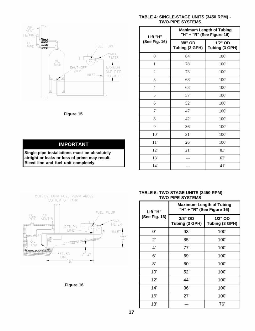
I. FUEL UNITS AND OIL LINES
SINGLE-PIPE OIL LINES - Standard burners areprovided with single-stage 3450 rpm fuel units withthe by-pass plug removed for single-pipe installations.
The single-stage fuel unit may be installed single-pipewith gravity feed or lift. Maximum allowable lift is 8feet. See Figure 15.
TWO-PIPE OIL LINES - For two-pipe systems wheremore lift is required, the two-stage fuel unit isrecommended. Table 4 (single-stage) and Table 5(two-stage) show allowable lift and lengths of 3/8-inchand 1/2-inch OD tubing for both suction and returnlines. Refer to Figure 16.
Be sure that all oil line connections are absolutelyairtight. Check all connections and joints. Flaredfittings are recommended. Do not use compressionfittings or PTFE ("Teflon®") tape.
Open the air-bleed valve and start the burner. Forclean bleed, slip a 3/16" ID hose over the end of thebleed valve and bleed into a container. Continue tobleed for 15 seconds after oil is free of air bubbles.Stop burner and close valve.
requires less fuel to be burned and sends less heatup the chimney.
A new boiler probably has a higher efficiency thanthe boiler being replaced. That probably means thatthe stack temperature from the new boiler will belower than that from the old boiler and with lessroom air being drawn up the chimney to dilute thestack gases. The combination of a large uninsulatedchimney, reduced firing rate, reduced firing time,lower stack temperature and less dilution air can, insome cases, contribute to the condensing of smallamounts of water vapor in the chimney. Suchcondensation, when it occurs, can cause chimneydeterioration. In extreme cases, condensed watermay be visible on the outside of the breeching orchimney. In those extreme cases, the chimney mayhave to be lined to insulate the chimney and thusprevent the condensation. The addition of dilutionair into the chimney may assist in drying thechimney interior surfaces.
A massive chimney on a cold, or exposed outsidewall may have produced adequate draft when it wasfired with a higher input and greater volumes ofheated gases. With reduced input and volume, thedraft may be severely affected. In one instance ourresearch showed a new chimney of adequate sizingproduced only -.035" W.C. after 30 minutes ofcontinuous firing at 13.0% CO
2. Outside wall
chimneys take longer to heat up and can have .00"W.C. draft at burner startup. You may have toconsider a special alloy chimney flue liner withinsulation around it and a stabilizing draft cap oreven a draft inducing fan in severe cases.
17
Lift "H"(See Fig. 16)
Maximum Length of Tubing"H" + "R" (See Figure 16)
3/8" ODTubing (3 GPH)
1/2" ODTubing (3 GPH)
0' 93' 100'
2' 85' 100'
4' 77' 100'
6' 69' 100'
8' 60' 100'
10' 52' 100'
12' 44' 100'
14' 36' 100'
16' 27' 100'
18' --- 76'
TABLE 5: TWO-STAGE UNITS (3450 RPM) - TWO-PIPE SYSTEMS
Figure 15
TABLE 4: SINGLE-STAGE UNITS (3450 RPM) - TWO-PIPE SYSTEMS
Lift "H"(See Fig. 16)
Manimum Length of Tubing"H" + "R" (See Figure 16)
3/8" ODTubing (3 GPH)
1/2" ODTubing (3 GPH)
0' 84' 100'
1' 78' 100'
2' 73' 100'
3' 68' 100'
4' 63' 100'
5' 57' 100'
6' 52' 100'
7' 47' 100'
8' 42' 100'
9' 36' 100'
10' 31' 100'
11' 26' 100'
12' 21' 83'
13' --- 62'
14' --- 41'
Figure 16
IMPORTANT
Single-pipe installations must be absolutelyairtight or leaks or loss of prime may result.Bleed line and fuel unit completely.
18
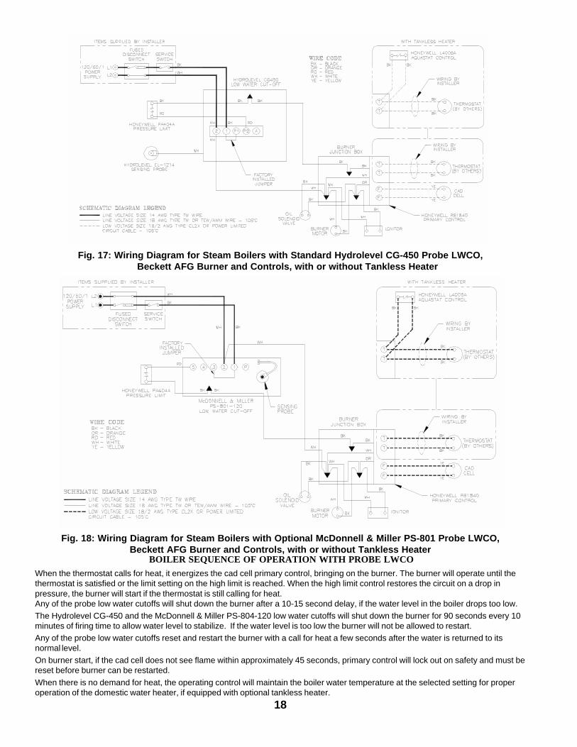
Fig. 18: Wiring Diagram for Steam Boilers with Optional McDonnell & Miller PS-801 Probe LWCO,Beckett AFG Burner and Controls, with or without Tankless Heater
Fig. 17: Wiring Diagram for Steam Boilers with Standard Hydrolevel CG-450 Probe LWCO, Beckett AFG Burner and Controls, with or without Tankless Heater
BOILER SEQUENCE OF OPERATION WITH PROBE LWCO
When the thermostat calls for heat, it energizes the cad cell primary control, bringing on the burner. The burner will operate until thethermostat is satisfied or the limit setting on the high limit is reached. When the high limit control restores the circuit on a drop inpressure, the burner will start if the thermostat is still calling for heat.Any of the probe low water cutoffs will shut down the burner after a 10-15 second delay, if the water level in the boiler drops too low.The Hydrolevel CG-450 and the McDonnell & Miller PS-804-120 low water cutoffs will shut down the burner for 90 seconds every 10minutes of firing time to allow water level to stabilize. If the water level is too low the burner will not be allowed to restart.Any of the probe low water cutoffs reset and restart the burner with a call for heat a few seconds after the water is returned to itsnormal level.On burner start, if the cad cell does not see flame within approximately 45 seconds, primary control will lock out on safety and must bereset before burner can be restarted.
When there is no demand for heat, the operating control will maintain the boiler water temperature at the selected setting for properoperation of the domestic water heater, if equipped with optional tankless heater.
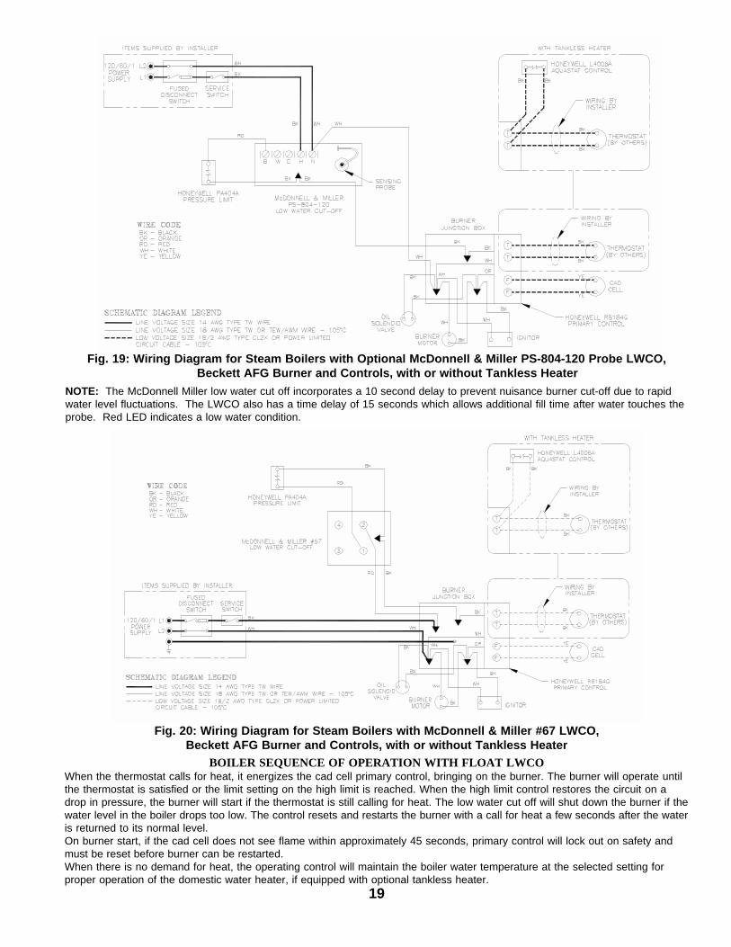
19
NOTE: The McDonnell Miller low water cut off incorporates a 10 second delay to prevent nuisance burner cut-off due to rapidwater level fluctuations. The LWCO also has a time delay of 15 seconds which allows additional fill time after water touches theprobe. Red LED indicates a low water condition.
BOILER SEQUENCE OF OPERATION WITH FLOAT LWCOWhen the thermostat calls for heat, it energizes the cad cell primary control, bringing on the burner. The burner will operate untilthe thermostat is satisfied or the limit setting on the high limit is reached. When the high limit control restores the circuit on adrop in pressure, the burner will start if the thermostat is still calling for heat. The low water cut off will shut down the burner if thewater level in the boiler drops too low. The control resets and restarts the burner with a call for heat a few seconds after the wateris returned to its normal level.On burner start, if the cad cell does not see flame within approximately 45 seconds, primary control will lock out on safety andmust be reset before burner can be restarted.When there is no demand for heat, the operating control will maintain the boiler water temperature at the selected setting forproper operation of the domestic water heater, if equipped with optional tankless heater.
Fig. 20: Wiring Diagram for Steam Boilers with McDonnell & Miller #67 LWCO,Beckett AFG Burner and Controls, with or without Tankless Heater
Fig. 19: Wiring Diagram for Steam Boilers with Optional McDonnell & Miller PS-804-120 Probe LWCO, Beckett AFG Burner and Controls, with or without Tankless Heater
TS-39- -C Rev. O

20
Fig. 22: Wiring Diagram for Water Boilers with Beckett AFG Burner and Controls, with Tankless Heater
Fig. 21: Wiring Diagram for Water Boilers with Beckett AFG Burner and Controls, without Tankless Heater
SEQUENCE OF OPERATIONA call for heat by the thermostat energizes the L8148A control which in turn energizes the R4184D primary control to turn on theburner. If burner ignites within approximately 45 seconds and the cad cell sees flame, the burner will continue to operate until the callfor heat is satisfied or the setting of the high limit is reached. The circulator will operate as long as the thermostat is calling for heat. Ifthe thermostat is not satisfied and the high limit is reached, the circulator will continue to operate, and the burner will stop until the highlimit is closed by a drop in boiler water temperature.
SEQUENCE OF OPERATIONA call for heat by the thermostat energizes the L8124C control which in turn energizes the R4184D primary control to turn on theburner. If burner ignites within approximately 45 seconds and the cad cell sees flame the burner will continue to operate until the callfor heat is satisfied. The circulator will also operate when the thermostat calls for heat if the boiler water temperature is up to the settingof the low limit in the L8124C control. If boiler water temperature is below the low limit setting the burner will operate but the circulatorwill not, giving preference to the domestic hot water demand.On call for heat by the thermostat the burner will continue to operate until the thermostat is satisfied or the setting of the high limit isreached. If the thermostat is not satisfied when the high limit is reached the burner will stop but the circulator will continue to operateuntil the thermostat is satisfied. Any time the boiler water temperature drops below the setting of the low limit the burner will beenergized in order to maintain domestic water temperature.

21
SECTION IV: OPERATING AND SERVICE INSTRUCTIONS
WARNING
All boilers equipped with burner swing door have a potential hazard which can cause severe propertydamage, personal injury or loss of life if ignored. Before opening swing door, turn off service switch toboiler to prevent accidental firing of burner outside the combustion chamber. Be sure to tighten swing doorfastener completely when service is completed.
(Note - If make-up water line is equipped withpressure reducing valve, system willautomatically fill to 12 psi. Leave globe valveopen).
j. Open isolation valve in boiler supply piping.
k. Remove hose from bib cock.
C. CHECK CONTROLS, WIRING AND BURNER to besure that all connections are tight and burner is rigid,that all electrical connections have been completed andfuses installed, and that oil tank is filled and oil lineshave been tested.
D. LUBRICATION — Follow instruction on burner andcirculator label to lubricate, if oil lubricated. Mostmotors currently used on residential type burnersemploy permanently lubricated bearings and thus donot require any field lubrication. Water lubricatedcirculators do not need field lubrication.
Do not over-lubricate. This can cause as much troubleas no lubrication at all.
E. SET CONTROLS with burner service switch turned“OFF”.
1. SET ROOM THERMOSTAT about 10° aboveroom temperature.
2. PRESS RED RESET BUTTON on primary control(R4184D/R8184G) and release.
3. On STEAM BOILERS, set cut-in pressure onPA404 pressuretrol for three (3) pounds anddifferential pressure for two (2) pounds. Thesepressures may be varied to suit individualrequirements of installation.
4. On STEAM BOILERS WITH TANKLESSDOMESTIC WATER HEATERS, set boiler watertemperature dial on L4006 operating control at190°F (max.). Set differential at 10°.
5. On WATER BOILERS WITHOUT TANKLESSHEATERS, set high limit dial on L8148 at 210°F.This temperature may be varied to suitrequirements of installation.
6. On WATER BOILERS WITH TANKLESSHEATERS, set operating control dial (low limit) onL8124 at 190°F and high limit dial at 210°F.Operating control (low limit) must be a minimumof 20° below high limit setting. Set differential at25°.
A. ALWAYS INSPECT INSTALLATION BEFORESTARTING BURNER.
B. FILL HEATING SYSTEM WITH WATER.
NOTE: It is important, especially in a steam system,to properly remove the oil and dirt from the system.Failure to clean the system can result in erratic waterlines and surging.
CLEAN HEATING SYSTEM IF boiler water orcondensate return water is dirty or if erratic water linesor surging exist after a few days of boiler operation.
Refer to step "N" for proper cleaning instructions forsteam and water boilers.
1. STEAM BOILERS — Fill boiler to normal waterline. Refer to Figure No. 1C.
2. HOT WATER BOILERS. Fill entire heating systemwith water and vent air from system. Use thefollowing procedure on a series loop or multi-zonedsystem installed as per Figure 9, to remove air fromsystem when filling:
a. Close isolation valve in boiler supply piping.
b. Isolate all circuits by closing zone valves orbalancing valves.
c. Attach a hose to bib cock located just belowisolation valve in boiler supply piping.
(Note - Terminate hose in five gallon bucket at asuitable floor drain or outdoor area).
d. Starting with one circuit, open zone valve.
e. Open bib cock.
f. Open fill valve (make-up water line should belocated directly above isolation valve in boilersupply piping).
g. Allow water to overflow from bucket untildischarge from hose is bubble free for 30seconds.
h. Open zone valve to the second zone to bepurged, then close the first. Repeat this stepuntil all zones have been purged, but alwayshave one zone open. At completion, open allzone valves.
i. Close bib cock, continue filling the system untilthe pressure gauge reads 12 psi. Close fill valve.

22
F. REMOVE GUN ASSEMBLY
1. Items to be checked are nozzle size, type, andangle; head size (and setting on MD(V1)head); gunsetting; and positioning of electrodes. Thisinformations is shown in Figures 23 and 24 andTable 6 (at rear of manual).
2. Reinstall gun assembly.
G. ADJUST OIL BURNER BEFORE STARTING.
1. SET BURNER AIR BAND AND AIR SHUTTER,see Table 6 at rear of manual..
2. OPEN ALL OIL LINE VALVES.
3. Attach a plastic hose to fuel pump vent fitting andprovide a pan to catch the oil.
4. REMOVE GAUGE PORT PLUG from fuel pumpand install pressure gauge capable of reading atleast 150 PSI.
5. OPEN FLAME OBSERVATION DOOR on frontof boiler.
H. START OIL BURNER.
1. Open vent fitting on fuel pump.
2. TURN ‘ON’ BURNER service switch and allowburner to run until oil flows from vent fitting in aSOLID stream without air bubbles forapproximately 10 seconds.
3. Close vent fitting and burner flame should startimmediately.
I. ADJUST OIL PRESSURE.
1. Locate oil pressure adjusting screw and turn screwto obtain 140 PSI pressure (100 PSI for V74Ronly).
2. DO NOT REMOVE PRESSURE GAUGE untillater.
J. OTHER ADJUSTMENTS
1. ADJUST THE AIR BAND AND/OR AIRSHUTTER.
Adjust air supply by loosening lock screws andmoving the air shutter and if necessary the air band.Refer to Table 6 for preliminary settings.
2. ADJUST THE COMBUSTION HEAD.
V72 thru V77; V713 and V714:
"L1" and "F" head burners have a fixed head whichis non-adjustable. To check combustion headlocation refer to Figure 24.
V78 & V79:
“V1” (variable) head burners have the ability tocontrol air by moving the head either forward orback.
Loosen the adjusting plate assembly hold downscrew. Slide the head and plate to the requiredfiring rate setting as shown in Figure 24. Tightenthe screw and knurled nut.
It might be necessary to move the head forward orback one position at a time to optimize the smokeand CO
2 readings. See Figure 24.
3. ADJUST DRAFT REGULATOR for a draftof — .02” (water gauge) over the fire after chimneyhas reached operating temperature and whileburner is running.
4. READJUST AIR BANDS on burner for a lightorange colored flame while the draft over the fire is—.02”. Use a smoke tester and adjust air forminimum smoke (not to exceed #1) with aminimum of excess air. Make final check usingsuitable instrumentation to obtain a CO
2 of 11.5 to
12.5% with draft of —.02” (water gauge) in firebox. These settings will assure a safe and efficientoperating condition. If the flame appears stringyinstead of a solid fire, try another nozzle of thesame type. Flame should be solid and compact.After all adjustments are made recheck for a draftof —.02” over the fire.
Fig. 23: "F" Head Electrode Positioning and GunSetting (Beckett AFG)
(Non-Burnham DrawingCopy from other Manual)
NOTICE
Burner-specific references in the following instructions pertain to the Beckett AFG, supplied asstandard equipment. For optional burners, Riello R40 and Carlin EZ-1HP and 102CRD-3, consultTable 6 at the rear of this manual for specifications, the instruction booklet shipped with theburner, and the appropriate Supplemental Instructions shipped with the boiler:
Supplemental Instructions for: Riello R40 Carlin EZ-1HP Carlin 102CRD-3
Burnham Part Number 8142761 8142759 8142760
23
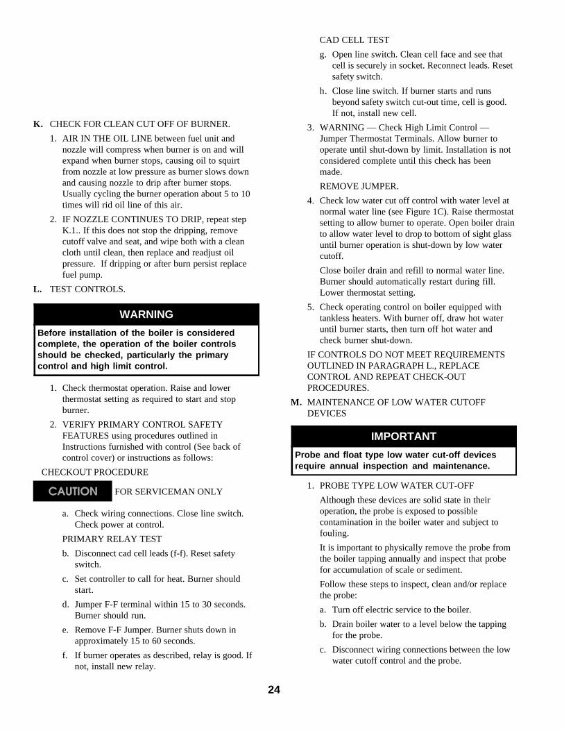
5. TURN “OFF” BURNER and remove pressuregauge. Install gauge port plug and tighten. Startburner again.
6. CAD CELL LOCATION AND SERVICEThe burner is supplied with a cadmium sulfideflame detector mounted at the factory, mounted onthe bottom of the ignitor. See Figure 25. To servicecad cell or to replace the plug in portion, swingopen the ignitor. After service is complete, be sureto fasten down the ignitor.
7. FLAME FAILUREThe V7 boiler controls operate the burnerautomatically. If for unknown reasons the burnerceases to fire and the reset button on the primarycontrol has tripped, the burner has experiencedignition failure. Before pressing the reset buttoncall your serviceman immediately.
Fig. 24: "L1" and "V1" Head Electrode Positioning and Gun Setting (Beckett AFG)
(Non-Burnham Drawing,Copy from LE Manual, 81433010R4, Page 13, without"Figure 12A, 12B, 12C and 12D"; sample enclosed)
Figure 25: Cad Cell Location
24
K. CHECK FOR CLEAN CUT OFF OF BURNER.
1. AIR IN THE OIL LINE between fuel unit andnozzle will compress when burner is on and willexpand when burner stops, causing oil to squirtfrom nozzle at low pressure as burner slows downand causing nozzle to drip after burner stops.Usually cycling the burner operation about 5 to 10times will rid oil line of this air.
2. IF NOZZLE CONTINUES TO DRIP, repeat stepK.1.. If this does not stop the dripping, removecutoff valve and seat, and wipe both with a cleancloth until clean, then replace and readjust oilpressure. If dripping or after burn persist replacefuel pump.
L. TEST CONTROLS.
WARNING
Before installation of the boiler is consideredcomplete, the operation of the boiler controlsshould be checked, particularly the primarycontrol and high limit control.
1. Check thermostat operation. Raise and lowerthermostat setting as required to start and stopburner.
2. VERIFY PRIMARY CONTROL SAFETYFEATURES using procedures outlined inInstructions furnished with control (See back ofcontrol cover) or instructions as follows:
CHECKOUT PROCEDURE
FOR SERVICEMAN ONLY
a. Check wiring connections. Close line switch.Check power at control.
PRIMARY RELAY TEST
b. Disconnect cad cell leads (f-f). Reset safetyswitch.
c. Set controller to call for heat. Burner shouldstart.
d. Jumper F-F terminal within 15 to 30 seconds.Burner should run.
e. Remove F-F Jumper. Burner shuts down inapproximately 15 to 60 seconds.
f. If burner operates as described, relay is good. Ifnot, install new relay.
CAD CELL TEST
g. Open line switch. Clean cell face and see thatcell is securely in socket. Reconnect leads. Resetsafety switch.
h. Close line switch. If burner starts and runsbeyond safety switch cut-out time, cell is good.If not, install new cell.
3. WARNING — Check High Limit Control —Jumper Thermostat Terminals. Allow burner tooperate until shut-down by limit. Installation is notconsidered complete until this check has beenmade.
REMOVE JUMPER.
4. Check low water cut off control with water level atnormal water line (see Figure 1C). Raise thermostatsetting to allow burner to operate. Open boiler drainto allow water level to drop to bottom of sight glassuntil burner operation is shut-down by low watercutoff.
Close boiler drain and refill to normal water line.Burner should automatically restart during fill.Lower thermostat setting.
5. Check operating control on boiler equipped withtankless heaters. With burner off, draw hot wateruntil burner starts, then turn off hot water andcheck burner shut-down.
IF CONTROLS DO NOT MEET REQUIREMENTSOUTLINED IN PARAGRAPH L., REPLACECONTROL AND REPEAT CHECK-OUTPROCEDURES.
M. MAINTENANCE OF LOW WATER CUTOFFDEVICES
IMPORTANT
Probe and float type low water cut-off devicesrequire annual inspection and maintenance.
1. PROBE TYPE LOW WATER CUT-OFF
Although these devices are solid state in theiroperation, the probe is exposed to possiblecontamination in the boiler water and subject tofouling.
It is important to physically remove the probe fromthe boiler tapping annually and inspect that probefor accumulation of scale or sediment.
Follow these steps to inspect, clean and/or replacethe probe:
a. Turn off electric service to the boiler.
b. Drain boiler water to a level below the tappingfor the probe.
c. Disconnect wiring connections between the lowwater cutoff control and the probe.
25
d. Dismount the low water cutoff control from theprobe.
e. Unscrew the probe from the boiler tapping.
f. Inspect that portion of the probe that is exposedto the boiler water for a scale or sedimentbuildup.
g. Light deposits may be removed by wiping theprobe with a damp cloth. Wiping the probe witha cloth soaked in vinegar will remove moretenacious lime deposits. The most stubborndeposits may be removed from the probe byusing a diluted amount, 3 parts of water to 1part of phosphoric acid (H
2PO
4).
CAUTION
Exercise caution when handling phosphoric acidand follow the instruction label on its container.
h. Clean the pipe threads of the probe to removeold, hardened pipe dope and other foreignmatter.
i. Apply a moderate amount of good quality pipedope to the pipe threads on the probe, leavingthe two end threads bare. Do not use PTFE(Teflon) tape.
j. Screw the probe into the boiler tapping.
k. Mount the low water cutoff control on the probe.
l. Reconnect the control to probe wiring.
m. Fill the boiler to its normal waterline.
n. Add boiler water treatment compound as needed(refer to paragraph N.).
o. Restore electric service to the boiler.
p. Fire burner to bring the water in the boiler to aboil to drive off free oxygen.
q. WARNING — BEFORE RETURNINGBOILER TO SERVICE: Follow the low watercutoff check out procedure in step L.4..
2. FLOAT TYPE LOW WATER CUT-OFF
During the heating season, if an external low watercutoff is on the boiler, the blow off valve should beopened once a month (use greater frequency whereconditions warrant), to flush out the sedimentchamber so the device will be free to functionproperly.
Low-water cutoffs and water feeders should bedismantled annually by qualified personnel, to theextent necessary to insure freedom fromobstructions and proper functioning of the workingparts. Inspect connecting lines to boiler foraccumulation of mud, scale, etc., and clean as
required. Examine all visible wiring for brittle orworn insulation and make sure electrical contactsare clean and that they function properly. Givespecial attention to solder joints on bellows andfloat when this type of control is used. Check floatfor evidence of collapse and check mercury bulb(where applicable) for mercury separation ordiscoloration. Do not attempt to repair mechanismsin the field. Complete replacement mechanisms,including necessary gaskets and installationinstructions are available from the manufacturer.
N. BOILER AND SYSTEM CLEANINGINSTRUCTIONS FOR TROUBLE FREEOPERATION.
1. STEAM BOILERS
a. Oil, greases & sediments which accumulate in anew boiler and piping must be removed from thesystem in order to prevent an unsteady waterline and carry over of the water into the supplymain above boiler.
Operate the boiler with steam in the entiresystem for a few days allowing the condensate toreturn to the boiler. If the condensate cantemporarily be wasted, operate boiler only forthe length of time it takes for condensate to runclear. If the latter cannot be achieved or if thecondensate is returned to the boiler, boil out theboiler using the SURFACE BLOWOFFconnection, see Figure 4.
i. Drain boiler until 1” of water is visible ingauge glass. Run temporary 1½” pipe linefrom the surface blowoff connection to anopen drain or some other location where hotwater may be discharged safely. Do notinstall valve in this line.
ii. Drain about 5 gallons of hot water fromboiler into a container and dissolve into itan appropriate amount of recommendedboil out compound. Remove safety valve &add solution to boiler water thru exposedtapping using a funnel.
NOTICE
Check with local authorities or consult localwater treatment services for acceptable chemicalcleaning compounds.
iii. Start burner and operate sufficiently to boilthe water without producing steam pressure.Boil for about 5 hours. Open boiler feedpipe sufficiently to permit a steady trickle ofwater from the surface blowoff pipe.

26
v. When boiler has cooled down sufficiently(crown sheet of sections are not too hot totouch), close the drain cocks at boiler and inreturn main and feed water slowly up tonormal level in boiler. Turn on oil burnerand allow boiler to steam for 10 minutes,then turn off burner. Draw off one quart ofwater from bottom gauge glass fitting anddiscard. Draw off another quart sample andif this sample is not clear, repeat the cycleof draining the boiler and return main andrefilling the boiler until sample is clear.
vi. If the boiler water becomes dirty again at alater date due to additional sedimentloosened up in the piping, close gate valvein Hartford Loop, open drain cock in returnmain, turn on oil burner and allowCondensate to flow to drain until it has runclear for at least 30 minutes while feedingwater to boiler so as to maintain normalwater level. Turn off oil burner, drainboiler, open gate valve in Hartford Loop,then repeat step 1 above.
e. Make pH or Alkalinity Test.
After boiler and system have been cleaned andrefilled as previously described, test the pH ofthe water in the system. This can easily be doneby drawing a small sample of boiler water andtesting with hydrion paper which is used in thesame manner as litmus paper, except it givesspecific readings. A color chart on the side ofthe small hydrion dispenser gives the reading inpH. Hydrion paper is inexpensive andobtainable from any chemical supply house orthrough your local druggist. The pH should behigher than 7, but lower than 11. Add some ofthe washout chemical (caustic soda), ifnecessary, to bring the pH within the specifiedrange.
f. Boiler is now ready to be put into service.
2. WATER BOILERS
a. Filling of Boiler and System — General —-In ahot water heating system, the boiler and entiresystem (other than the expansion tank) must befull of water for satisfactory operation. Watershould be added to the system until the boilerpressure gauge registers 12 psi. To insure thatthe system is full, water should come out of allair vents when opened.
b. Boiling Out of Boiler and System. The oil andgrease which accumulate in a new hot waterboiler can be washed out in the followingmanner.
i. Remove safety relief valve using extremecare to avoid damaging it.
ii. Add an appropriate amount of
Continue this slow boiling and trickle ofoverflow for several hours until the watercoming from the overflow is clear.
iv. Stop burner and drain boiler in a mannerand to a location that hot water can bedischarged with safety.
v. Refill boiler to normal water line. If waterin gauge glass does not appear to be clear,repeat steps (i. thru iii.) and boil out theboiler for a longer time.
b. Low pressure steam boilers such as the V7Series should be maintained with appropriatewater treatment compounds. Add suitable watertreatment compounds as recommended by yourqualified water treatment company.
c. Remove temporary surface blowoff piping, plugtapping and reinstall safety valve. Boil or bringwater temperature to 180°F promptly in order todrive off the dissolved gases in the fresh water.
d. If unsteady water line, foaming or primingpersist, install gate valve in Hartford Loop anddrain valves in return main and at boiler asshown in Figure 8 and proceed as follows:
i Connect hoses from drain cocks to floordrain. Close gate valve in Hartford Loopand open drain cock in return main. Fillboiler to normal water level, turn on oilburner and operate boiler at this water levelfor at least 30 minutes after the condensatebegins to run hot, then turn off burner.
Close all radiator valves. Remove all supplymain air valves and plug the openings insupply main.
ii. Draw about 5 gallons of hot water fromboiler into a container and dissolve into itthe appropriate amount of a recommendedboilout compound. Remove safety valvefrom boiler and pour this solution intoboiler, then reinstall safety valve.
iii. Turn on oil burner and keep operatingwhile feeding water to boiler slowly. Thiswill raise water level in boiler slowly so thatwater will be boiling hot and will riseslowly into supply main and back throughreturn main, flowing from drain hose atabout 180°F. Continue until water runsclear from drain hose for at least 30minutes.
iv. Stop feeding water to boiler but continueoperating oil burner until excess water inboiler flows out through supply main andwater lowers (by steaming) until it reachesnormal level in boiler. Turn off oil burner.Drain boiler. Open all radiator valves.Reinstall all supply main air valves. Opengate valve in Hartford Loop.

27
recommended boil out compound.
iii. Replace safety relief valve.
iv. Fill the entire system with water.
v. Start firing the boiler.
vi. Circulate the water through the entiresystem.
vii. Vent the system, including the radiation.
viii. Allow boiler water to reach operatingtemperature, if possible.
ix. Continue to circulate the water for a fewhours.
x. Stop firing the boiler.
xi. Drain the system in a manner and to alocation that hot water can be dischargedwith safety.
xii. Remove plugs from all available returns andwash the water side of the boiler asthoroughly as possible, using a high-pressure water stream.
xiii. Refill the system with fresh water.
c. Add appropriate boiler water treatmentcompounds as recommended by your qualifiedwater treatment company.
d. Make pH or Alkalinity Test.
After boiler and system have been cleaned andrefilled as previously described, test the pH ofthe water in the system. This can easily be doneby drawing a small sample of boiler water andtesting with hydrion paper which is used in thesame manner as litmus paper, except it givesspecific readings. A color chart on the side ofthe small hydrion dispenser gives the readingpH. Hydrion paper is inexpensive andobtainable from any chemical supply house orthru your local druggist. The pH should behigher than 7 but lower than 11. Addappropriate water treatment chemicals, ifnecessary, to bring the pH within the specifiedrange. With this lower level of protection, caremust be exercised to eliminate all of the freeoxygen in the system.
e. Boiler is now ready to be put into service.
O. HINTS ON COMBUSTION
1. NOZZLES — Although the nozzle is a relativelyinexpensive device, its function is critical to thesuccessful operation of the oil burner. The selectionof the nozzle supplied with the V7 boiler is theresult of extensive testing to obtain the best flameshape and efficient combustion. Other brands of thesame spray angle and spray pattern may be used butmay not perform at the expected level of CO
2 and
smoke. Nozzles are delicate and should be protectedfrom dirt and abuse. Nozzles are mass-produced
and can vary from sample to sample. For all ofthose reasons a spare nozzle is a desirable item fora serviceman to have.
2. FLAME SHAPE — Looking into the combustionchamber through the observation door, the flameshould appear straight with no sparklers rolling uptoward the crown of the chamber. If the flame dragsto the right or left, sends sparklers upward or makeswet spots on the target wall, the nozzle should bereplaced. If the condition persists look for fuelleaks, air leaks, water or dirt in the fuel asdescribed above.
3. FUEL LEAKS — Any fuel leak between the pumpand the nozzle will be detrimental to goodcombustion results. Look for wet surfaces in the airtube, under the ignitor, and around the air inlet.Any such leaks should be repaired as they maycause erratic burning of the fuel and in the extremecase may become a fire hazard.
4. AIR LEAKS — Any such leaks should be repaired,as they may cause erratic burning of the fuel and inextreme cases may become a fire hazard.
5. GASKET LEAKS — If 11.5 to 12.5% CO2 with a
#1 smoke cannot be obtained in the breeching, lookfor air leaks around the burner mounting gasket,observation door, and canopy gasket. Such air leakswill cause a lower CO
2 reading in the breeching.
The smaller the firing rate the greater effect an airleak can have on CO
2 readings.
6. DIRT — A fuel filter is a good investment.Accidental accumulation of dirt in the fuel systemcan clog the nozzle or nozzle strainer and produce apoor spray pattern from the nozzle. The smaller thefiring rate, the smaller the slots become in thenozzle and the more prone to plugging it becomeswith the same amount of dirt.
7. WATER — Water in the fuel in large amounts willstall the fuel pump. Water in the fuel in smalleramounts will cause excessive wear on the pump, butmore importantly water doesn’t burn. It chills theflame and causes smoke and unburned fuel to passout of the combustion chamber and clog theflueways of the boiler.
8. COLD OIL — If the oil temperature approachingthe fuel pump is 40°F or lower poor combustion ordelayed ignition may result. Cold oil is harder toatomize at the nozzle. Thus, the spray droplets getlarger and the flame shape gets longer. An outsidefuel tank that is above grade or has fuel lines in ashallow bury is a good candidate for cold oil. Thebest solution is to bury the tank and lines deepenough to keep the oil above 40°F.
9. HIGH ALTITUDE INSTALLATIONS
Air openings must be increased at higher altitudes.Use instruments and set for 11.5 to 12.5% CO
2.

28
10. START-UP NOISE — Late ignition is the cause ofstart-up noises. If it occurs recheck for electrodesettings, flame shape, air or water in the fuel lines.
11. SHUT DOWN NOISE — If the flame runs out ofair before it runs out of fuel, an after burn withnoise may occur. That may be the result of a faultycut-off valve in the fuel pump, or it may be airtrapped in the nozzle line. It may take several firingcycles for that air to be fully vented through thenozzle. Water in the fuel or poor flame shape can
also cause shut down noises.
IMPORTANT
CHECK TEST PROCEDURE. A very good test forisolating fuel side problems is to disconnect thefuel system and with a 24" length of tubing, fireout of an auxiliary five gallon pail of clean, fresh,warm #2 oil from another source. If the burnerruns successfully when drawing out of theauxiliary pail then the problem is isolated to thefuel or fuel lines being used on the jobsite.
P. ATTENTION TO BOILER WHILE NOT INOPERATION.
1. IMPORTANT
IF BOILER IS NOT USED DURING WINTERTIME, IT MUST BE FULLY DRAINED TOPREVENT FREEZE DAMAGE.
2. Spray inside surfaces with light lubricating orcrankcase oil using gun with extended stem so as toreach all corners.
3. With steam boilers, at end of season add sufficientwater to fill boiler to top of water column and leaveit that way until fall when water should be drainedagain to proper level. If at this time boiler water isdirty, drain water, flush out boiler, and refill with
clean water to prescribed water level.
4. Always keep the manual fuel supply valve shut offif the burner is shut down for an extended period oftime.
5. To recondition the heating system in the fall seasonafter a prolonged shut down, follow the instructionsoutlined in Section IV, Items A through M.
CAUTION
This boiler contains controls which maycause the boiler to shut down and notrestart without service. If damage due tofrozen pipes is a possibility, the heatingsystem should not be left unattended incold weather; or appropriate safeguardsand alarms should be installed on theheating system to prevent damage if theboiler is inoperative.
IMPORTANT
SUCTION LINE LEAKS - THE OIL MUST BEFREE OF AIR. Try bleeding the pumpthrough a clear tube. There must be no frothvisible. There are various test kits availableto enable you to look at the oil through cleartubing adapted to the supply line at thepump fitting. Air eliminators are on themarket that have potential. Also, electronicsight glasses are being used with goodsuccess. At times, new tubing must be runto the tank or new fittings put on. Just makesure you get the air out.Any air leaks in the fuel line will cause anunstable flame and may cause delayedignition noises. Use only flare fittings in thefuel lines.
A leaky system will increase the volume of make-upwater supplied to the boiler which can significantlyshorten the life of the boiler. Entrained in make-upwater are dissolved minerals and oxygen. When thefresh, cool make-up water is heated in the boiler theminerals fall out as sediment and the oxygenescapes as a gas. Both can result in reduced boilerlife. The accumulation of sediment can eventuallyisolate the water from contacting the cast iron.When this happens the cast iron in that area getsextremely hot and eventually cracks. The presenceof free oxygen in the boiler creates a corrosiveatmosphere which, if the concentration becomeshigh enough, can corrode the cast iron throughfrom the inside. Since neither of these failure typesare the result of a casting defect the warranty doesnot apply. Clearly it is in everyone’s best interest toprevent this type of failure. The maintenance ofsystem integrity is the best method to achieve this.
Q. FREQUENT WATER ADDITION

29
AQUASTAT SWITCHING ACTION WITHIN L8124CCONTROL
The switching action within the L8124C control hasthree settings:
1. high limit2. low limit3. adjustable differential
HIGH LIMIT OPERATION —-The high limit opens and turns off the burner when the
water temperature reaches the set point. The high limitautomatically resets after the water temperature drops pastthe set point and through the 10°F differential.
Set the indicator at desired shutoff temperature.
LOW LIMIT OPERATION —-On a temperature rise, with the adjustable differential
at the minimum setting of 10°F, the burner circuit (R-B)breaks and the circulator circuit (R-W) makes at the lowlimit set point. On a temperature drop of 10°F below the setpoint, the R-B circuit makes and the R-W circuit breaks.
ADJUSTABLE DIFFERENTIAL —-At any differential setting greater than 10°F, the R-B
make temperature and R-W break temperature will remainthe same-control setting minus 10°F. The R-B break and R-W make temperature will be the set point temperature plusthe difference between the differential setting and 10°F.
EXAMPLE: Set point of 140°F; differential set at 25°F.On a temperature rise, R-B will break and R-W will makeat 155°F. On a temperature fall, R-B will make and R-Wwill break at 130°F.
Set low limit indicator at the minimum temperaturerecommended for domestic hot water supply. This settingmust be at least 20°F below high limit setting to preventone switch from locking out the other.
Set the differential the desired number of degrees.25°F differential gives longest burner cycles.
AQUASTAT SWITCHING ACTION WITHIN L8148ACONTROLS
The switching action in the L8148A control has onesetting, the high limit. The switching relay is controlled bythe low voltage room thermostat. On a call for heat, therelay contacts make to complete the line voltage circulatorcircuit and also the burner circuit if the boiler watertemperature is below the high limit setting. The high limitswitch shuts off the burner if boiler water temperatureexceeds the high limit setting.
Set the indicator at the desired shutoff temperature.
(Non-Burnham DrawingCopy from other Manual)
SECTION V: BOILER CLEANING
WARNING
All boiler cleaning must be comp leted with burner serv ice switch turned o ff. Boilersequipped with burner swing do or have a potent ia l hazard wh ich can cause severe propertydamage, per sonal injury or loss of l ife if ignor ed. Before opening swing door, tu rn offservice switch to boiler to prevent accidenta l firing of burner outside the co mbustioncham ber. Be sure to t igh ten swing door fastener completely when serv ice is completed.

30
WARNINGThe boiler must be connected to an approvedchimney in good condition. Serious property damagecould result if the boiler is connected to a dirty orinadequate chimney. The interior of the chimney fluemust be inspected and cleaned before the start of theheating season and should be inspected periodicallythroughout the heating season for any obstructions.A clean and unobstructed chimney flue is necessaryto allow noxious fumes that could cause injury or lossof life to vent safely and will contribute towardmaintaining the boiler's efficiency.
Figure 26: Cleaning of Boiler Flueways
A. CLEAN THE FLUEWAYS (See Figure 26).1. Prior to cleaning boiler, lay a protective cloth or
plastic over combustion chamber blanket to collectdebris falling from flueways.
2. For access to firebox
On boilers with burner swing door and flexible fuelline(s), remove fastener securing door and swingdoor open. For full access to firebox, remove burnerand swing door from mounting plate by pullinghairpin cotter from bottom of hinge pin andremoving pin from hinge. Set burner aside. Removeswing door mounting plate, see Figure 6.
3. For cleaning from the side:
a. Lift the jacket's upper right side access panel offto expose the flue cleanout plates.
b. Loosen nuts securing the flue cleanout platesand remove the plates. The insulation should beremoved with the plates taking care not todamage the insulation.
4. For cleaning from the top:
a. Lift the jacket's upper right side access panel offto allow removal of the jacket top panel.
b. Remove as much smokepipe as necessary toallow removal of the jacket top panel andcanopy (smokebox).
c. Remove the jacket top panel.
d. Remove the canopy, being careful not to damagethe ceramic fiber gasket.
5. Using a 1¼” diameter wire or fibre bristle brush(30” handle) clean the flueways. Brush from the topand/or side using horizontal and diagonal strokesfor best results. DO NOT allow brush to strike thetarget wall or liner in the chamber.
B. CLEAN TOP OF BOILER SECTIONS (if cleaningfrom the top).Brush and vacuum the tops of the boiler sections.
C. CLEAN THE FIREBOX.Using wire or fibre bristle brush, clean crown of boilerand inside of water legs. DO NOT allow brush to striketarget wall or blanket in the combustion chamber.
D. AFTER CLEANING, remove protective cloth withdebris and vacuum as necessary, but be careful not todamage blanket. Inspect target wall, combustionchamber blanket, burner mounting plate insulation andburner swing door insulation for signs of damage. Ifdamaged, replace as needed.
E. REASSEMBLE BOILER.CAUTION: Do not start the burner unless canopy,
smokepipe, burner mounting plate, burner swing doorand all flue plates are secured in place.
1. Install the canopy taking care to align the gasketswithout blocking the flueways. If gasket isdamaged, replace as needed.
2. Reinstall flue plates, making sure gasket on eachplate is in place and forms gas tight seal. Ifdamaged replace as needed.
3. Reinstall jacket top panel and secure with sheetmetal screws. Replace jacket upper right side accesspanel.
4. Reinstall smokepipe on canopy and secure to collarwith sheet metal screws.
5. Install swing door mounting plate to front sectionwith fasteners, see Figure 6.
6. Reinstall burner in reverse order of disassemblyoutlined in paragraph A.2 above. For details, seeFigure 6.

31
SECTION VI: REPAIR PARTS
All V7 Series Repair Parts may be obtained through your local Burnham Wholesale distributor. Should you require assistancein locating a Burnham Distributor in your area, or have questions regarding the availability of Burnham products or repairparts, please contact your Burnham Regional Sales Office as listed below.
Contact Regional Office Indicated for your State
Alabama A Nebraska A Oregon A
Alaska A Nevada A Pennsylvania D
Arizona A New Hampshire B Rhode Island B
Arkansas A New Jersey South Carolina A
California A Atlantic, Burlington, Camden,
D
South Dakota A
Colorado A Cape May, Cumberland, Tennessee A
Connecticut B Gloucester, Mercer, Texas A
Delaware D Monmouth, Ocean, Salem Utah A
Florida A Counties Vermont B
Georgia A All other Counties C Virginia
Hawaii A New Mexico A Arlington,Accomack,Clarke,
DIdaho A New York Fairfax,Frederick,Fauquier,
Illinois A Albany, Fulton, Montgomery,
B
Loudoun,Northampton and
Indiana A Rensselaer, Saratoga, Prince William Counties
Iowa A Schenectady, Schoharie, All other Counties A
Kansas A Warren, Washington Counties Washington A
Kentucky A All Other Counties C Washington, D.C. D
Louisiana A North Carolina A West Virginia D
Maine B North Dakota A Wisconsin A
Maryland D Ohio Wyoming A
Massachusetts B Athens, Belmont, Gallia,
DMichigan A Jefferson, Lawrence, Meigs,
Minnesota A Monroe, and Washington
Mississippi A Counties
Missouri A All other Counties A
Montana A Oklahoma A Canada A
Burnham Corporation Regional Offices
A. Burnham Corporation - Central & Western RegionsP.O. Box 3079Lancaster, PA 17604-3079Phone: (717) 481-8400FAX: (717) 481-8408
C. Burnham Corporation - Metropolitan RegionP.O. Box 3079Lancaster, PA 17604-3079Phone: (717) 481-8400FAX: (717) 481-8409
B. Burnham Sales Corporation - Northeast Region19-27 Mystic AvenueSomervil le, MA 02145Phone: (617) 625-9735FAX: (617) 625-9736
D. Burnham Corporation - Mid-At lantic RegionP.O. Box 3079Lancaster, PA 17604-3079Phone: (717) 481-8400FAX: (717) 481-8409
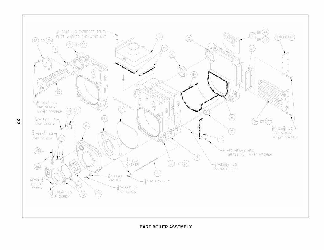
32
BARE BOILER ASSEMBLY

33
ItemNo.
Description Part No. V72 V713 V73 V714 V74 V75 V76 V77 V78 V79
BARE BOILER ASSEMBLY (See Page 32 for Illustration)
1Front Section (Non-Htr.), Machined Water 71727019 1 --- 1 --- 1 1 1 1 1 1
Front Section (Non-Htr.), Machined Water 71727015 --- 1 --- 1 --- --- --- --- --- ---
1A Front Section (Non-Htr.), Machined Steam 71727018 --- --- 1 --- 1 1 1 1 1 1
2Front Section w/Htr. Opening, MachinedWater
71727016 --- --- 1 --- 1 1 1 1 1 1
2AFront Section w/Htr. Opening, MachinedSteam
71727017 --- --- 1 --- 1 1 1 1 1 1
3Center Section 7172202 --- 1 --- 2 --- --- --- --- --- ---
Center Section 71727021 --- --- 1 --- 2 3 4 5 6 7
4 Narrow Back Section (Non-Htr.), Machined 7172204 --- 1 --- 1 --- --- --- --- --- ---
4AWide Back Section (Non-Htr.), MachinedWater
71727033 1 --- 1 --- 1 1 1 1 1 1
4BWide Back Section (Non-Htr.), MachinedSteam
71727034 --- --- 1 --- 1 1 1 1 1 1
5Rear Section w/Htr. Opening, Machined 7172203 --- 1 --- 1 --- --- --- --- --- ---
Rear Section w/Htr. Opening, Machined 71727036 --- --- 1 --- 1 1 1 1 1 1
6 5" Cast Iron Slip Nipple 7066003 1 --- 2 --- 3 4 5 6 7 8
7 2½" Cast Iron Slip Nipple 7066001 1 4 2 6 3 4 5 6 7 8
8 Rear Target Wall Insulation 8202701 1 1 1 1 1 1 1 1 1 1
8A
Combustion Chamber Liner, ½" x 23" x 4" 82027023 1 --- --- --- --- --- --- --- --- ---
Combustion Chamber Liner, ½" x 24" x 5" 82022033 --- 1 --- --- --- --- --- --- --- ---
Combustion Chamber Liner, ½" x 23" x 8" 82027031 --- --- 1 --- --- --- --- --- --- ---
Combustion Chamber Liner, ½" x 24" x 9" 82022043 --- --- --- 1 --- --- --- --- --- ---
Combustion Chamber Liner, ½" x 23" x 12" 82027041 --- --- --- --- 1 --- --- --- --- ---
Combustion Chamber Liner, ½" x 23" x 16" 82027051 --- --- --- --- --- 1 --- --- --- ---
Combustion Chamber Liner, ½" x 23" x 20" 82027061 --- --- --- --- --- --- 1 --- --- ---
Combustion Chamber Liner, ½" x 23" x 24" 82027071 --- --- --- --- --- --- --- 1 --- ---
Combustion Chamber Liner, ½" x 23" x 28" 82027081 --- --- --- --- --- --- --- --- 1 ---
Combustion Chamber Liner, ½" x 23" x 32" 82027091 --- --- --- --- --- --- --- --- --- 1
9
Tie Rod, 3/8"-16 x 7¾" Lg. 80861072 2 --- --- --- --- --- --- --- --- ---
Tie Rod, 3/8"-16 x 12½" Lg. 80861010 --- 2 2 --- --- --- --- --- --- ---
Tie Rod, 3/8"-16 x 17" Lg. 80861011 --- --- --- 2 2 --- --- --- --- ---
Tie Rod, 3/8"-16 x 20¾" Lg. 80861012 --- --- --- --- --- 2 --- --- --- ---
Tie Rod, 3/8"-16 x 25¼" Lg. 80861013 --- ---- --- --- --- --- 2 --- --- ---
Tie Rod, 3/8"-16 x 27½" Lg. 80861014 --- --- --- --- --- --- --- 2 --- ---
Tie Rod, 3/8"-16 x 31½" Lg. 80861015 --- --- --- --- --- --- --- --- 2 ---
Tie Rod, 3/8"-16 x 36½" Lg. 80861036 --- --- --- --- --- --- --- --- --- 2
CONTINUED ON PAGES 34 AND 35

34
BARE BOILER ASSEMBLY (CONTINUED)

35
CONTINUED FROM PAGE 33
ItemNo.
Description Part No. V72 V713 V73 V714 V74 V75 V76 V77 V78 V79
BARE BOILER ASSEMBLY (See Page 34 for Illustration)
10 Flue Cover Plate Assembly 6112214 1 2 2 3 3 4 5 6 7 8
11 Heater Cover Plate Gasket - Front Heater 8036068 --- --- 1 --- 1 1 1 1 1 1
11A Heater Cover Plate Gasket - Rear Heater 8036058 --- 1 1 1 1 1 1 1 1 1
12 Blank Heater Cover Plate (WB) - Front Heater 7036002 --- --- 1 --- 1 1 1 1 1 1
12ATapped Heater Cover Plate (WBTL) - FrontHeater
7036001 --- --- 1 --- 1 1 1 1 1 1
12BBlank Heater Cover Plate (SB & WB) - RearHeater
7036020 --- --- 1 --- 1 1 1 1 1 1
12CTapped Heater Cover Plate (WBTL) - RearHeater
7036021 --- 1 1 1 1 1 1 1 1 1
13222A Heater Carton Assy. - (WBT) Front Heater
---OR---A54 Heater Carton Assy. - (WBT) Front Heater
6036036
6031204
---
---
---
---
1
---
---
---
1
---
1
---
1
---
1
1
1
1
11
13AV1-2 Heater Assy. - (SBT & WBT) - RearHeater
6036031 --- 1 1 --- 1 1 1 1 1 1
13B V1-1 Heater Carton Assy. - (WBT) Rear Heater 6036030 --- --- --- 1 --- --- --- --- --- ---
14 Burner Swing Door Mounting Plate 7172705 1 1 1 1 1 1 1 1 1 1
14A Burner Swing Door Mounting Plate Insulation 82027021 1 1 1 1 1 1 1 1 1 1
15 Rope Gasket - Burner Mounting Plate - 53" Lg. 72027014 1 1 1 1 1 1 1 1 1 1
16 Burner Swing Door 7172706 1 1 1 1 1 1 1 1 1 1
16A Burner Swing Door Insulation 82027022 1 1 1 1 1 1 1 1 1 1
16B Rope Gasket (Burner Swing Door) - 28" Lg. 72027015 1 1 1 1 1 1 1 1 1 1
16C Hinge 7022701 2 2 2 2 2 2 2 2 2 2
16D Hinge Pin 80861614 1 1 1 1 1 1 1 1 1 1
16E Hairpin Cotter 80861667 1 1 1 1 1 1 1 1 1 1
17 Observation Port Cover 7026001 1 1 1 1 1 1 1 1 1 1
18 Spring 3/8" I.D. x ½" Lg. 8026015 1 1 1 1 1 1 1 1 1 1
19 Canopy Sealing Strip (½" x 1" x 98") 7202710 1 1 1 1 1 1 1 1 1 1
20
V72 Canopy Assembly, Type II 611270211 1 --- --- --- --- --- --- --- --- ---
V713 Canopy Assembly 611270313 --- 1 --- --- --- --- --- --- --- ---
V73 Canopy Assembly, Type II 611270311 --- --- 1 --- --- --- --- --- --- ---
V714 Canopy Assembly 611270413 --- --- --- 1 --- --- --- --- --- ---
V74 Canopy Assembly, Type II 611270411 --- --- --- --- 1 --- --- --- --- ---
V75 Canopy Assembly, Type II 611270511 --- --- --- --- --- 1 --- --- --- ---
V76 Canopy Assembly, Type II 611270611 --- --- --- --- --- --- 1 --- --- ---
V77 Canopy Assembly, Type II 611270711 --- --- --- --- --- --- --- 1 --- ---
V78 Canopy Assembly, Type II 611270811 --- --- --- --- --- --- --- --- 1 ---
V79 Canopy Assembly, Type II 611270911 --- --- --- --- --- --- --- --- --- 1

36
TS-39-112-D
V713 and V714 FLUSH JACKET

37
Item No. Description Part No. V713 V714
V713 and V714 Flush Jacket Components - Items 1 thru 6 Include Insulation As Part of Assembly
1 Jacket Front Panel Assembly 60427097 1 1
2 Jacket Rear Panel Assembly 60427096 1 1
3 Jacket Left Side/Top Panel Assembly604270314 1 ---
604270414 --- 1
4 Jacket Top Panel Assembly604270322 1 ---
604270422 --- 1
5 Jacket Lower Right Side Panel Assembly604270337 1 ---
604270437 --- 1
6
Jacket Upper Right Side Access Panel Assembly without Heater Opening (WBOnly)
604270336 1 ---
604270436 --- 1
Jacket Upper Right Side Access Panel Assembly with Heater Opening (WBT Only)604270335 1 ---
604270435 --- 1
7Jacket Bracket (WB Only) 7042715
1 1Jacket Bracket (WBT Only) 7042714

38
V72 Thru V79 FLUSH JACKET
TS-39-109-D

39
ItemNo.
Description Part No. V72 V73 V74 V75 V76 V77 V78 V79
V72 Thru V79 Flush Jacket Components - Items 1 thru 7 Include Insulation As Part of Ass'y
1
Jacket Front Panel Ass'y w/o Htr. Opg. (Wtr. Blr.) 60427090 1
1 1 1 1 1 1 1Jacket Front Panel Ass'y w/o Htr. Opg. (Stm. Blr.) 60427091 ---
Jacket Front Panel Ass'y w/Htr. Opg. (Wtr. Blr.) 60427092 ---
Jacket Front Panel Ass'y w/Htr. Opg. (Stm. Blr.) 60427094 ---
2 Plastic Collar Extension-Jkt. Frt. Panel w/Htr. Opg. 8032704 --- 1 1 1 1 1 1
3 Jacket Rear Panel Assembly 60427093 1 1 1 1 1 1 1 1
4 Jacket Left Side/Top Panel Assembly
604270241 1 --- --- --- --- --- --- ---
604270341 --- 1 --- --- --- --- --- ---
604270441 --- --- 1 --- --- --- --- ---
604270541 --- --- --- 1 --- --- --- ---
604270641 --- --- --- --- 1 --- --- ---
604270741 --- --- --- --- --- 1 --- ---
604270841 --- --- --- --- --- --- 1 ---
604270941 --- --- --- --- --- --- --- 1
5 Jacket Top Panel Assembly
604270221 1 --- --- --- --- --- --- ---
604270321 --- 1 --- --- --- --- --- ---
604270421 --- --- 1 --- --- --- --- ---
604270521 --- --- --- 1 --- --- --- ---
604270621 --- --- --- --- 1 --- --- ---
604270721 --- --- --- --- --- 1 --- ---
604270821 --- --- --- --- --- --- 1 ---
604270921 --- --- --- --- --- --- --- 1
6 Jacket Lower Right Side Panel Assembly
604270234 1 --- --- --- --- --- --- ---
604270334 --- 1 --- --- --- --- --- ---
604270434 --- --- 1 --- --- --- --- ---
604270534 --- --- --- 1 --- --- --- ---
604270634 --- --- --- --- 1 --- --- ---
604270734 --- --- --- --- --- 1 --- ---
604270834 --- --- --- --- --- --- 1 ---
604270934 --- --- --- --- --- --- --- 1
7
Jacket Upper Right Side Access Panel Assemblywithout Heater Opening
604270233 1 --- --- --- --- --- --- ---
604270333 --- 1 --- --- --- --- --- ---
604270433 --- --- 1 --- --- --- --- ---
604270533 --- --- --- 1 --- --- --- ---
604270633 --- --- --- --- 1 --- --- ---
604270733 --- --- --- --- --- 1 --- ---
604270833 --- --- --- --- --- --- 1 ---
604270933 --- --- --- --- --- --- --- 1
Jacket Upper Right Side Access Panel Assemblywith Heater Opening
604270332 --- 1 --- --- --- --- --- ---
604270432 --- --- 1 --- --- --- --- ---
604270532 --- --- --- 1 --- --- --- ---
604270632 --- --- --- --- 1 --- --- ---
604270732 --- --- --- --- --- 1 --- ---
604270832 --- --- --- --- --- --- 1 ---
604270932 --- --- --- --- --- --- --- 1

40
V73 Thru V79 STEAM BOILERS - TRIM AND CONTROLS

41
ItemNo.
Description Part No. V73 V74 V75 V76 V77 V78 V79
V73 Thru V79 STEAM BOILERS - TRIM AND CONTROLS (See Page 40 for Illustration)
1. Draft Regulator
1A DR-6 Draft Regulator 8116029 1 1 1 1 --- --- ---
1B DR-7 Draft Regulator 8116001 --- --- --- --- 1 1 1
2. Instruction Envelope Containing:
2A Installation and Operating Instructions 8142711 1 1 1 1 1 1 1
2B 10 Year Lim ited Warranty Mailer (Steam Boilers) 81460121 1 1 1 1 1 1 1
2C I=B=R Pamphlet 81460061 1 1 1 1 1 1 1
3. Probe Low Water Cutoff
3A
Low Water Cutoff, Hydrolevel CG450 (less probe) 80160628
1 1 1 1 1 1 1Low Water Cutoff, McDonnell & Miller PS-801-120 80160624
Low Water Cutoff, McDonnell & Miller PS-804-120 80160662
3B Probe, Hydrolevel EL-1214 (Hydrolevel CG450) 80160629 1 1 1 1 1 1 1
3C Limit, Honeywell PA404A1009 80160300 1 1 1 1 1 1 1
3D Syphon, ¼ NPT x 4" x 180° 806603030 1 1 1 1 1 1 1
3D1 Bushing, ¾ NPT x ¼ NPT 806600508 1 1 1 1 1 1 1
3D2 Elbow, ¾ NPT 806601520 1 1 1 1 1 1 1
3D3 Nipple, ¾ NPT x 2" 806600003 1 1 1 1 1 1 1
3E Gage Glass Set, 6", ConBraCo 20-104-10 8056091 1 1 1 1 1 1 1
4. Float Low Water Cutoff
4A Low Water Cutoff, McDonnell & Miller 67 80160597 1 1 1 1 1 1 1
4B Limit, Honeywell PA404A1009 80160300 1 1 1 1 1 1 1
4C Syphon, ¼ NPT x 4" x 180° 806603030 1 1 1 1 1 1 1
4D Gage Glass Set, 6", ConBraCo 20-104-10 8056091 1 1 1 1 1 1 1
5. Miscellaneous Trim and Controls
5A Oil Pr imary Control, Honeywell R8184G1286 80160416 1 1 1 1 1 1 1
5BSafety Valve, ¾ NPT, 15 psi, ConBraCo 13-511-08
81660530 1 1 1 1 1 1 1
5B1 Coupling, ¾ NPT 806602561 1 1 1 1 1 1 1
5B2 Nipple, ¾ NPT x 8" 806600221 1 1 1 1 1 1 1
5C Drain Valve, ¾ NPT, ConBraCo 31-606-02 806603011 1 1 1 1 1 1 1
5C1 Bushing, 1½ NPT x ¾ NPT 806600507 1 1 1 1 1 1 1
5D Limit, Honeywell L4006A2015 (SBPT & SBFT) 80160400 1 1 1 1 1 1 1
5E Well, ¾ NPT x 1½ ", Honeywell 123890A 80160426 1 1 1 1 1 1 1
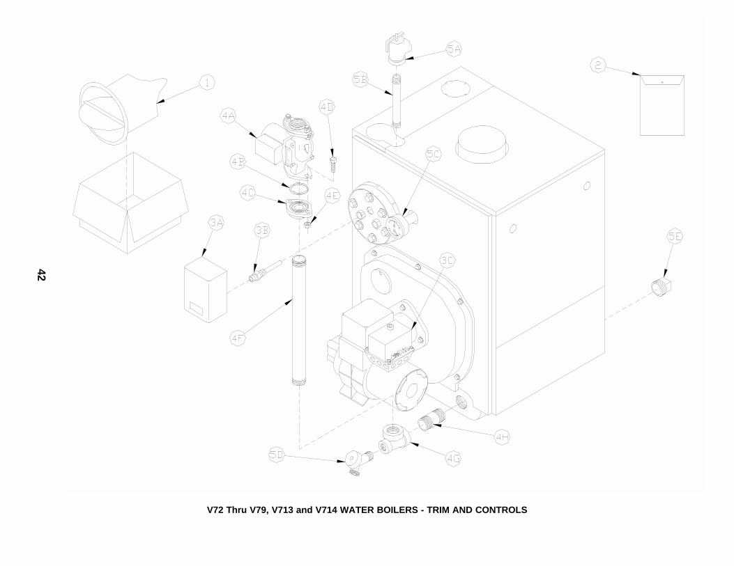
42
V72 Thru V79, V713 and V714 WATER BOILERS - TRIM AND CONTROLS

43
ITEMNO.
DESCRIPTION Part No. V72 V713 V73 V714 V74 V75 V76 V77 V78 V79
V72 Thru V79, V713 and V714 WATER BOILERS - TRIM AND CONTROLS (See Page 42 for Illustration)
1. DRAFT REGULATOR
1A DR-6 Draft Regulator 8116029 1 1 1 1 1 1 1 ---- ---- ----
1B DR-7 Draft Regulator 8116001 ---- ---- ---- ---- ---- ---- ---- 1 1 1
2. INSTRUCTION ENVELOPE CONTAINING:
2A Installation and Operating Instructions 8142711 1 1 1 1 1 1 1 1 1 1
2BLimited Warranty Mailer (WaterBoilers)
81460135 1 1 1 1 1 1 1 1 1 1
2C I=B=R Pamphlet 81460061 1 1 1 1 1 1 1 1 1 1
3. CONTROLS
3A
Honeywell L8148A1090 Hi Limit, Circ.Relay (WB)--OR --Honeywell L8124C1102 Hi & Lo Limit,Circ. Relay (WBT)
80160449U
80160406U
1
----
1
1
1
1
1
1
1
1
1
1
1
1
1
1
1
1
1
1
3B
Honeywell #123870A Immersion Well,¾NPT x 1½ Insulation (WB)-- OR --Honeywell #123872A Immersion Well,½NPT x 3" Insulation (WBT)
80160426
80160497
1
----
1
1
1
1
1
1
1
1
1
1
1
1
1
1
1
1
1
1
3CHoneywell R4184D (1027/1001)Protectorelay
80160473 1 1 1 1 1 1 1 1 1 1
4. CIRCULATOR & PIPING (Packaged Boiler Only)
4A Circulator, Taco 007F (position 2) 8056007 1 1 1 1 1 1 1 1 1 1
4B Gasket, Taco "00" Series Circulator 806602006 2 2 2 2 2 2 2 2 2 2
4C Circulator Flange, 1½"NPT 806602014 2 2 2 2 2 2 2 2 2 2
4DCap Screw, Hex Head, 7/16" -14 x1½"
80861301 4 4 4 4 4 4 4 4 4 4
4E Hex Nut, 7/16" - 14 80860406 4 4 4 4 4 4 4 4 4 4
4F Nipple, 1½"NPT x18" 806600011 1 1 1 1 1 1 1 1 1 1
4G Tee, 1½" x ¾" x 1½"NPT, Black 806601003 1 1 1 1 1 1 1 1 1 1
4H Nipple, 1½"NPT x 3" 806600006 1 1 1 1 1 1 1 1 1 1
5. MISCELLANEOUS WATER TRIM
5ARelief Valve, ¾"NPT, F/F 30 LB,Conbraco 10-408-05
81660319 1 1 1 1 1 1 1 1 1 1
5B Nipple, ¾"NPT x 8" 806600221 1 1 1 1 1 1 1 1 1 1
5CTemp/Pressure Gauge, 2½" Dia.,ENFM #41042.5210
8056169U 1 1 1 1 1 1 1 1 1 1
5DDrain Cock, ¾"NPT Short Shank(WB and WBT), Conbraco #31-606-02
806603011 1 1 1 1 1 1 1 1 1 1
5E
Plug, Square Head, 1½"NPT(Packaged)
806603515
1 1 1 1 1 1 1 1 1 1Reducing Bushing, 1½" x ¾"NPT(Knockdown)
80660507

44
Beckett AFG Burner
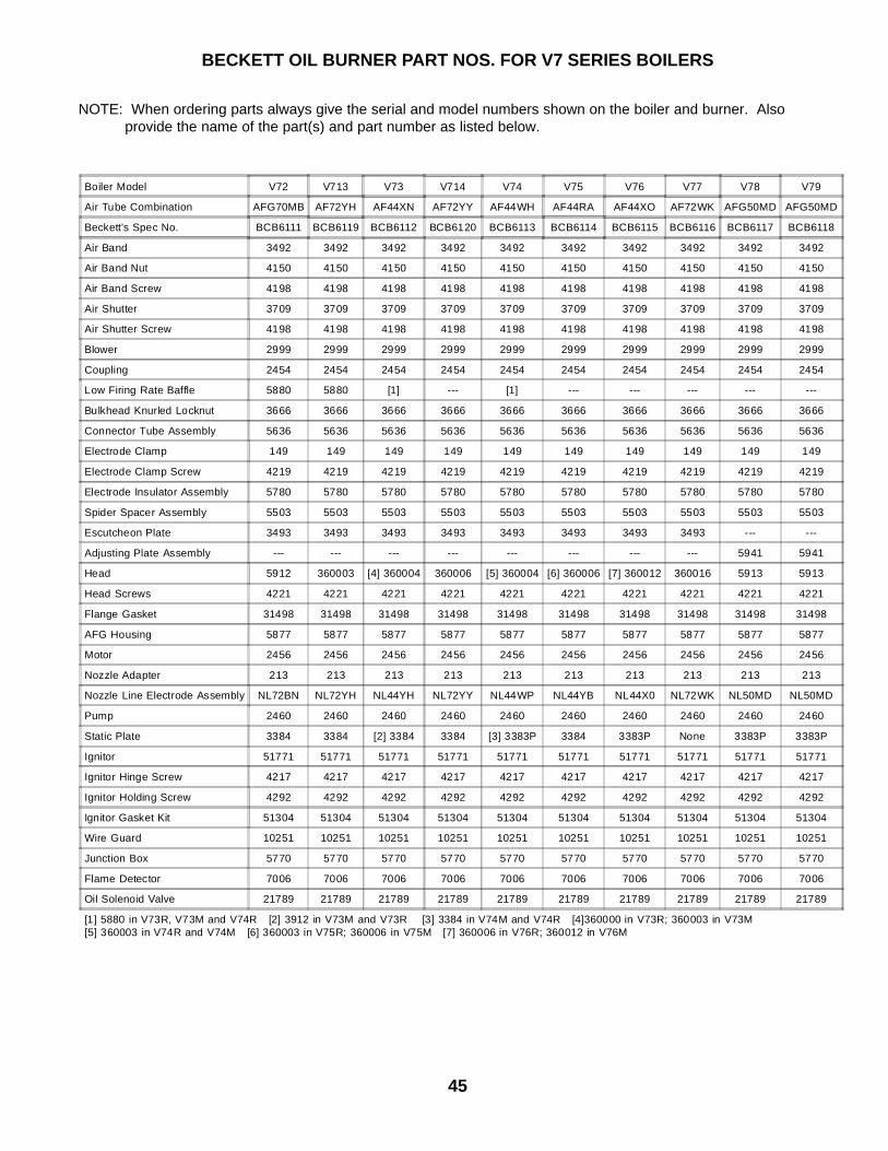
45
BECKETT OIL BURNER PART NOS. FOR V7 SERIES BOILERS
NOTE: When ordering parts always give the serial and model numbers shown on the boiler and burner. Also provide the name of the part(s) and part number as listed below.
Boiler Model V72 V713 V73 V714 V74 V75 V76 V77 V78 V79
Air Tube Combination AFG70MB AF72YH AF44XN AF72YY AF44WH AF44RA AF44XO AF72WK AFG50MD AFG50MD
Beckett's Spec No. BCB6111 BCB6119 BCB6112 BCB6120 BCB6113 BCB6114 BCB6115 BCB6116 BCB6117 BCB6118
Air Band 3492 3492 3492 3492 3492 3492 3492 3492 3492 3492
Air Band Nut 4150 4150 4150 4150 4150 4150 4150 4150 4150 4150
Air Band Screw 4198 4198 4198 4198 4198 4198 4198 4198 4198 4198
Air Shutter 3709 3709 3709 3709 3709 3709 3709 3709 3709 3709
Air Shutter Screw 4198 4198 4198 4198 4198 4198 4198 4198 4198 4198
Blower 2999 2999 2999 2999 2999 2999 2999 2999 2999 2999
Coupling 2454 2454 2454 2454 2454 2454 2454 2454 2454 2454
Low Firing Rate Baffle 5880 5880 [1] --- [1] --- --- --- --- ---
Bulkhead Knurled Locknut 3666 3666 3666 3666 3666 3666 3666 3666 3666 3666
Connector Tube Assembly 5636 5636 5636 5636 5636 5636 5636 5636 5636 5636
Electrode Clamp 149 149 149 149 149 149 149 149 149 149
Electrode Clamp Screw 4219 4219 4219 4219 4219 4219 4219 4219 4219 4219
Electrode Insulator Assembly 5780 5780 5780 5780 5780 5780 5780 5780 5780 5780
Spider Spacer Assembly 5503 5503 5503 5503 5503 5503 5503 5503 5503 5503
Escutcheon Plate 3493 3493 3493 3493 3493 3493 3493 3493 --- ---
Adjusting Plate Assembly --- --- --- --- --- --- --- --- 5941 5941
Head 5912 360003 [4] 360004 360006 [5] 360004 [6] 360006 [7] 360012 360016 5913 5913
Head Screws 4221 4221 4221 4221 4221 4221 4221 4221 4221 4221
Flange Gasket 31498 31498 31498 31498 31498 31498 31498 31498 31498 31498
AFG Housing 5877 5877 5877 5877 5877 5877 5877 5877 5877 5877
Motor 2456 2456 2456 2456 2456 2456 2456 2456 2456 2456
Nozzle Adapter 213 213 213 213 213 213 213 213 213 213
Nozzle Line Electrode Assembly NL72BN NL72YH NL44YH NL72YY NL44WP NL44YB NL44X0 NL72WK NL50MD NL50MD
Pump 2460 2460 2460 2460 2460 2460 2460 2460 2460 2460
Static Plate 3384 3384 [2] 3384 3384 [3] 3383P 3384 3383P None 3383P 3383P
Ignitor 51771 51771 51771 51771 51771 51771 51771 51771 51771 51771
Ignitor Hinge Screw 4217 4217 4217 4217 4217 4217 4217 4217 4217 4217
Ignitor Holding Screw 4292 4292 4292 4292 4292 4292 4292 4292 4292 4292
Ignitor Gasket Kit 51304 51304 51304 51304 51304 51304 51304 51304 51304 51304
Wire Guard 10251 10251 10251 10251 10251 10251 10251 10251 10251 10251
Junction Box 5770 5770 5770 5770 5770 5770 5770 5770 5770 5770
Flame Detector 7006 7006 7006 7006 7006 7006 7006 7006 7006 7006
Oil Solenoid Valve 21789 21789 21789 21789 21789 21789 21789 21789 21789 21789
[1] 5880 in V73R, V73M and V74R [2] 3912 in V73M and V73R [3] 3384 in V74M and V74R [4]360000 in V73R; 360003 in V73M[5] 360003 in V74R and V74M [6] 360003 in V75R; 360006 in V75M [7] 360006 in V76R; 360012 in V76M

46
Print word document

47