Installation of Grouted Jacket to Protect Existing Major Water Pipes ...
20
Page 1 of 20 Installation of Grouted Jacket to Protect Existing Major Water Pipes for Trenchless Construction in Hong Kong Ir. Maurice W. W. Lee a , Ir. Quentin K. T. Yau a , Ir. K. W. Mak b , Ir. S. S. Lam b and Ir. F. C. Lui b a Maurice Lee & Associates Ltd. b Drainage Services Department, Government of the Hong Kong SAR, China ABSTRACT To sustain development of our first new town, Tsuen Wan, drainage improvement works were carried out in Tsuen Wan and its adjacent district Kwai Chung in order to alleviate flooding impact to them. One of the major works of the drainage improvement was to lay a large diameter stormwater pipe across heavily trafficked Texaco Road which is a strategic road and houses numerous underground utilities such as gas pipes, storm and foul drains, power cables and pressurized water mains including a freshwater trunk main and an asbestos cement saltwater main. To carry out the drainage improvement works under the above site constraints while to ensure a safe and healthy working environment as well as to minimize disturbance to the residents in the neighborhood, we devised an innovative grouted jacket as a major protection measure to existing water mains for laying of stormwater pipe by trenchless construction. The grouted jacket could overcome the inadequacy of soil arching strength due to shallow soil cover, eliminate the risk of flooding the workers inside the pipe bore in case of bursting of water main, and confine the pipe jacking activities within the grouted jacket. To construct the grouted jacket, ODEX drilling method was adopted with a revised Tube-A-Manchette (TAM) grouting method. Successful completion of the grouted jacket and pipe jacking for the drainage improvement works were achieved. Keywords : Grouted Jacket, Water Mains, Trenchless Construction, Safety. 1. INTRODUCTION The application of pipe jacking techniques is becoming more and more common in the urban areas of Hong Kong to circumvent the traffic problems brought by road openings. Unlike open-trench construction, the underground utilities cannot be exposed and diverted by trenchless method during construction. Alignments of the underground utilities have to be accurately ascertained before commencement of pipe jacking in order to avoid them from the
Transcript of Installation of Grouted Jacket to Protect Existing Major Water Pipes ...
Page 1 of 20
Installation of Grouted Jacket to Protect Existing Major Water
Pipes for Trenchless Construction in Hong Kong
Ir. Maurice W. W. Leea, Ir. Quentin K. T. Yau
a,
Ir. K. W. Makb, Ir. S. S. Lam
b and Ir. F. C. Lui
b
aMaurice Lee & Associates Ltd.
bDrainage Services Department, Government of the Hong Kong SAR, China
ABSTRACT
To sustain development of our first new town, Tsuen Wan, drainage improvement works were carried
out in Tsuen Wan and its adjacent district Kwai Chung in order to alleviate flooding impact to them.
One of the major works of the drainage improvement was to lay a large diameter stormwater pipe
across heavily trafficked Texaco Road which is a strategic road and houses numerous underground
utilities such as gas pipes, storm and foul drains, power cables and pressurized water mains including a
freshwater trunk main and an asbestos cement saltwater main. To carry out the drainage improvement
works under the above site constraints while to ensure a safe and healthy working environment as well
as to minimize disturbance to the residents in the neighborhood, we devised an innovative grouted
jacket as a major protection measure to existing water mains for laying of stormwater pipe by
trenchless construction. The grouted jacket could overcome the inadequacy of soil arching strength due
to shallow soil cover, eliminate the risk of flooding the workers inside the pipe bore in case of bursting
of water main, and confine the pipe jacking activities within the grouted jacket. To construct the
grouted jacket, ODEX drilling method was adopted with a revised Tube-A-Manchette (TAM) grouting
method. Successful completion of the grouted jacket and pipe jacking for the drainage improvement
works were achieved.
Keywords : Grouted Jacket, Water Mains, Trenchless Construction, Safety.
1. INTRODUCTION
The application of pipe jacking techniques is becoming more and more common in the urban
areas of Hong Kong to circumvent the traffic problems brought by road openings. Unlike
open-trench construction, the underground utilities cannot be exposed and diverted by
trenchless method during construction. Alignments of the underground utilities have to be
accurately ascertained before commencement of pipe jacking in order to avoid them from the
Page 2 of 20
first beginning as there will be no chance for the jacking pipe to twist and dodge around them
once pipe jacking is started.
There are cases when the upstream and downstream invert levels are fixed by existing
drainage system while the overburden soil strata is not adequately thick enough to enable full
soil arching effect to be mobilized above the jacking pipe, or the underground utilities are in
direct conflict with or in very close proximity to the proposed jacking pipe. The latter means
that diversions of these underground utilities are extremely difficult if not impossible, as the
utility undertakings would have to face the same traffic problem when they are trying to carry
out the road openings, expose and divert the utilities.
Such situation was faced by the project team for urban drainage improvement project in
Tsuen Wan and Kwai Chung of Hong Kong during the construction of a 1800mm diameter
stormwater pipe across Texaco Road near Tsuen Wing Street, Tsuen Wan. The Employer of
the project was Drainage Services Department (DSD) of the Government of Hong Kong SAR,
the Engineer of the project was Maurice Lee & Associates Ltd. and the Contractor was
Shanghai Urban Construction (Group) Corporation. The overburden soil of the stormwater
pipe was around 2.6m which was less than two times of the pipe diameter (1800mm)
necessary to utilize the soil arching effect according to normal practice. Further, among other
underground utilities, there were a 750mm diameter mild steel (MS) freshwater trunk main
and a 450mm diameter asbestos cement (AC) saltwater main. The latter was laid in 1970s
particularly attracted concerns because it was brittle. It was found only 890mm above the
external circumference of the proposed jacking pipe. See Figure 1.
Figure 1 Longitudinal profile of Texaco Road and effective span of the grouted jacket

Page 3 of 20
Texaco Road is a district distributor which connects Tsuen Kam Interchange in the north and
Tsuen Tsing Interchange in the south. The upstream stage of pipe jacking would cover three
lanes of Texaco Road, including the southbound slow lane, southbound fast lane, and a
northbound lane to Tai Wo Hau Road, and finally reached the planter in the middle of the
road under the Texaco Road Flyover.
The proposed 1800mm diameter pipe jacking works across Texaco Road have to be laid by
two stages. The downstream stage of 36.7m long was completed first as it was more
straightforward relatively. The upstream stage of 23.2m long, which would be completed
thereafter, would be in close proximity to the water mains.
Both the water mains were critical supply mains to Tsing Yi and Kwai Chung South districts.
Among them, the AC water main was more critical. It was durable in withstanding internal
water pressure, but relatively brittle and weaker than the MS water main in withstanding
excessive external load or pressure. Although use of AC pipe for both new works and
maintenance works has been discontinued for many years, but still there are plenty of such
pipes in the existing water supply system in Hong Kong [10]. Its normal operation pressure
was around 10 bars. Since AC material has a tendency to burst abruptly when damaged
instead of gradual breaking when compared with other pipe materials, risk assessment
indicated that if the subject AC water main bursts, water could burst out from the pipe at a
speed of around 1m3/s resulting considerable ground subsidence and imposing immediate
danger to the workers working under the jacking shield head as well as to the motorists and
pedestrians.
This paper discusses how this difficult situation was overcome with the satisfaction of the
stakeholders including maintenance authority of the watermains, i.e. Water Supplies
Department (WSD) of the Government of Hong Kong SAR.
2. SITE CONDITIONS
2.1 Exposure of underground utilities
When designing the pipe jacking works, the depth and alignment of the utilities under Texaco
Road had been reviewed by record drawings from utility undertakings, Ground Penetrating
Radar (GPR) detection and trial pit excavations as well as in the utilities co-ordination
meetings.

Page 4 of 20
The locations of the water mains were ascertained by few trial pit excavations. The freshwater
main was found to be around 2.1m below the southbound slow lane of Texaco Road while the
AC water main was around 1.8m below the southbound fast lane. In the longitudinal section,
they were at around 7.5m and 12m respectively from the upstream end of the 23.2m long
jacking pipe.
2.2 Geological formation under Texaco Road
From previous ground investigations, the geological formation under Texaco Road was
underlain by a 4.5m to 8.4m thick Fill layer. Beneath the Fill was a 1.5m to 4.8m thick
Completely to Highly Decomposed Granodiorite over bedrock. The proposed pipe jacking
works, around 4m below ground, would be completely within the Fill layer.
A horizontal borehole was drilled in May 2008 along the centerline of the upstream pipe
jacking alignment. The total 18.9m of drilling was entirely within the Fill stratum which was
described as “slightly sandy SILT / silty SAND with gravel / sandy GRAVEL / COBBLE
with gravel”. No groundwater was encountered during the whole drilling process despite it
was in the rainy season.
Aerial photograph interpretation showed that the areas around Texaco Road was within the
original coastal boundary of Tsuen Wan and was not reclaimed from sea. The Fill material
was most possibly deposited to form the required level for development.
Characteristics of Fill such as colour, compactness, consistency and grain size can vary over a
very wide range, dependent mainly on the origin of the material, and the methods of
placement and compaction [4]. The water content of the Fill excavated upstream and
downstream of the Texaco Road pipe jacking works varied from 9% to 23%, and therefore the
porosity (n) might be assumed to be ranged from 35% to 42%.
3. DESIGN CONCEPT
3.1 The adopted pipe jacking method
The open shield method was adopted for the pipe jacking works after consideration of its
short length and large diameter. Unlike the publicly known tunnel boring machine (TBM)
method, there would be no boring machine. Instead, manual workers were used to excavate
Page 5 of 20
the soil. A shield head which was a tubular steel structure with a diameter (slightly larger than
the spigot of the proposed jacking pipe) would be used as an excavation chamber for the
workers and a leading pipe for the jacking pipes to plug in and follow into the subsoil like a
train.
For such a large diameter pipe, the space of the shield head was adequate to accommodate 3
workers concurrently working inside. After excavating about 100mm deep into the soil, the
hydraulic jacks in the jacking pit would push the jacking pipes and the shield head into the
recently formed space to prevent the soil from collapsing.
Given the large pipe diameter, the bare soil exposed inside the shield head would be around
2m high which was susceptible to collapse, particularly after heavy rainstorms and where
groundwater level was high. From previous ground investigation, the groundwater level at
Texaco Road was measured at around 0.7m to 2.4m below ground, or 2.9m to 4.6m above the
jacking pipe. The actual water level was at around 1m above the jacking pipe. The major
threat was the bursting of the AC water main before the shield head went pass it (after passing
it, the shield head and jacking pipes would protect the work face from direct impact of the
water flushing out). The water flushed out would likely liquefy the soil in front of the shield
head causing a mud avalanche towards the pipe bore which would be extremely dangerous.
On the other hand, the shield head was not jacked into the soil but was pushed into the space
just excavated by the workers; this would make it easier to control the alignment and reduce
the pressure acting on the jacking pipe. The space was a bit larger than the external diameter
of the shield head and the jacking pipe. Therefore, there would be slightly over-breaking
around the circumference of the jacking pipe, allowing a space for re-structuring of the
overburden soil and settlement.
3.2 Prediction of settlement of the pipe jacking works
Pipe jacking in soft ground inevitably would cause ground movements. The smaller the over-
breaking, the lesser the magnitude of settlement would be. A straight as-built alignment of the
jacking pipe could help reducing over-breaking.
Prediction of settlement was carried out in the design stage by following the relationship
recommended by Mair et al. [6]. They demonstrated that the settlement profile would be in
the form of a trough (Gaussian distribution curve) along the centerline of the pipe jacking
alignment.

Page 6 of 20
Normal pipe jacking operation relies on the arch effect of the soil strata above the excavated
soil. In order to allow the arch to be completely and securely formed, the depth of soil cover
normally has to exceed 2 times the diameter of the jacking pipe (D). 3 times the D is preferred.
In the case of pipe jacking crossing Texaco Road, the depth of overburden soil was only 2.6m
or 1.4D, less than 2D. It would not enjoy the benefit of the arch effect and would be subject to
almost full overburden pressure, probably wide trench condition, which would increase the
friction between overburden soil and top of pipe, increase the risk of collapse of the
excavation face in front of the shield head, and increase the deflection magnitude of the
overburden soil during pipe jacking.
Further, the congested utilities, including the water mains, in the overburden soil were
stretching across the “arch zone” in a direction perpendicular to the pipe alignment, which
also prevented a full development of the arch effect. The utilities on the other hand would
share part of the overburden load, though in a very small scale with respect to their small
diameters.
Using a settlement model without arch effect, the prediction showed that the maximum
settlement was 16mm along the centerline of the jacking pipe and would gradually reduce to
0mm at around 4m from the centerline. This prediction was considered as within the normal
acceptable range of open shield pipe jacking. However, considering the nature of the AC
water main, WSD was concerned by their experience that any movement would cause it
suddenly burst without warning. According to current standard of Highways Department [5],
any trenchless works should not cause road settlement greater than 12mm over every 10m,
but this tolerance might be reduced subject to existence of any vulnerable structures nearby.
By this ratio, the upper limit for this 23.2m long upstream pipe jacking works was 28mm.
While it was impractical for the pipe jacking works to target for zero settlement, it was also
impractical to assume any settlement tolerance that the AC water main could sustain as it
would be subject to the degree of deterioration of the AC material, ground conditions,
moisture content, and previous movement / settlement.
In order to protect the water main from disturbance by soil movement, and thereby protect it
from bursting and endangering the safety of the labourers working inside the shield head, the
project team came up with a schematic proposal to construct a roofing between the AC water
main and the jacking pipe. It was aimed to confine the soil movement induced by the pipe
jacking operation below the roofing and therefore virtually allow the AC water main
undisturbed.
Page 7 of 20
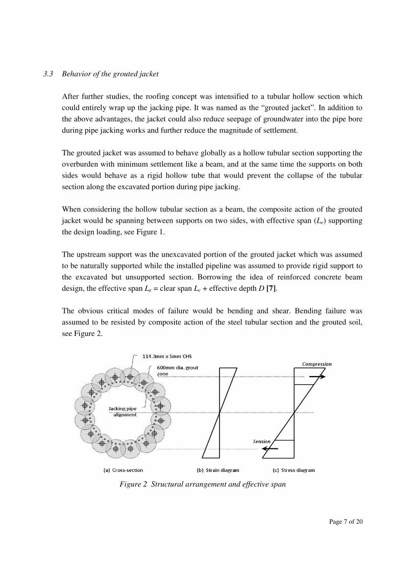
3.3 Behavior of the grouted jacket
After further studies, the roofing concept was intensified to a tubular hollow section which
could entirely wrap up the jacking pipe. It was named as the “grouted jacket”. In addition to
the above advantages, the jacket could also reduce seepage of groundwater into the pipe bore
during pipe jacking works and further reduce the magnitude of settlement.
The grouted jacket was assumed to behave globally as a hollow tubular section supporting the
overburden with minimum settlement like a beam, and at the same time the supports on both
sides would behave as a rigid hollow tube that would prevent the collapse of the tubular
section along the excavated portion during pipe jacking.
When considering the hollow tubular section as a beam, the composite action of the grouted
jacket would be spanning between supports on two sides, with effective span (Le) supporting
the design loading, see Figure 1.
The upstream support was the unexcavated portion of the grouted jacket which was assumed
to be naturally supported while the installed pipeline was assumed to provide rigid support to
the excavated but unsupported section. Borrowing the idea of reinforced concrete beam
design, the effective span Le = clear span Lc + effective depth D [7].
The obvious critical modes of failure would be bending and shear. Bending failure was
assumed to be resisted by composite action of the steel tubular section and the grouted soil,
see Figure 2.
Figure 2 Structural arrangement and effective span

Page 8 of 20
It was assumed that the grouted soil would provide adequate bonding to the sleeve grout pipe
so that composite action would take place, further test was recommended to justify the design
parameters.
When considering the support at the rigid hollow tube section, the rigid hollow section would
behave as a circular ring, subject to external pressure, there would be circumferential
compression and some circumferential bending.
The unfactored design loads consisted of overburden pressure, live load and traffic load,
which gave a total factored force of 255kN/m acting on the hollow section. The grouted jacket
was assumed to act as a reinforced cement-soil tubular hollow section resisting the load in
three modes as follow:
(i) circumferential compression as a cement-soil pipe,
(ii) longitudinal load as a hollow tubular structure, supported between the frame at jacking
pit and soil under the other end,
(iii) local flexural failure of the reinforcing CHS, supported between the shield head and
unexcavated grouted soil mass.
From the design, the grouted jacket consisted of a densely grouted cement-soil ring of
minimum 600mm thick surrounding the jacking pipe with 16 nos. 114.3mm × 5mm thick
circular hollow sections (CHS) as reinforcement evenly distributed along the circumference
of a 2765mm diameter circle. The length of grouted jacket should be at least 4m beyond the
position of the AC water main in order to strengthen the soil strata and enhance the arch effect
during pipe jacking, thus reduce the risk of settlement and failure of the AC water main.
Though the grouted jacket was assumed to behave as a hollow tubular structure, the
effectiveness of the grouted cement-soil pipe structure depends on:
(i) behavior of grouted soil,
(ii) quality control and testing data of grouted cement-soil is available,
(iii) tolerance of grout tube, thus the alignment of the grouted jacket and its reinforcing CHS.
A complete grouting of the pipe bore inside the grouted jacket (commonly called advance
grouting in pipe jacking works) was proposed as a redundancy to safeguard collapse of the
road section.
3.4 Cement grout mix
Page 9 of 20
Grouting has been frequently used as a means of improving the ground for constructional
purposes, either temporarily or permanently. By injection into the ground, it improves the soil
properties in terms of strength and permeability while bringing minimum disturbance to the
insitu soil, adjacent structures and inconvenience to the public.
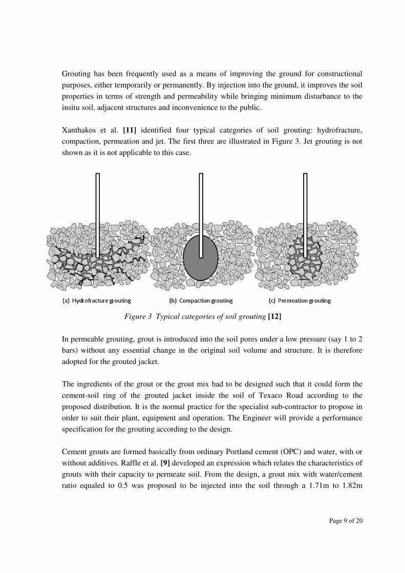
Xanthakos et al. [11] identified four typical categories of soil grouting: hydrofracture,
compaction, permeation and jet. The first three are illustrated in Figure 3. Jet grouting is not
shown as it is not applicable to this case.
Figure 3 Typical categories of soil grouting [12]
In permeable grouting, grout is introduced into the soil pores under a low pressure (say 1 to 2
bars) without any essential change in the original soil volume and structure. It is therefore
adopted for the grouted jacket.
The ingredients of the grout or the grout mix had to be designed such that it could form the
cement-soil ring of the grouted jacket inside the soil of Texaco Road according to the
proposed distribution. It is the normal practice for the specialist sub-contractor to propose in
order to suit their plant, equipment and operation. The Engineer will provide a performance
specification for the grouting according to the design.
Cement grouts are formed basically from ordinary Portland cement (OPC) and water, with or
without additives. Raffle et al. [9] developed an expression which relates the characteristics of
grouts with their capacity to permeate soil. From the design, a grout mix with water/cement
ratio equaled to 0.5 was proposed to be injected into the soil through a 1.71m to 1.82m

Page 10 of 20
equilateral spacing of holes. This was achieved by 16 nos. of holes along a 2765mm diameter
circle wrapping the jacking pipe, giving a spacing of 543mm.
Additives may be added to improve the characteristic of a grout. Grout with sodium silicate
(commonly known as LW grout) has the characteristics of better penetration under low
pressure and controllable gel time. The LW grout would quite easily hydro-fracture the loose
fill material to form a seam of hard grout and at the same time consolidate the adjacent soil by
compression [8]. It is comparatively impermeable, but its mechanical strength was not as high
as the traditional cement grout. Thus it might be used for grouting the pipe bore inside the
grouted jacket (advance grouting) since the soil inside the pipe bore would soon be excavated
so as to ease the worker’s task.
3.5 Method of permeation grouting
The most economical means of grout injection for shallow depth is through the driven lance,
inserted into the ground by hammer or pneumatic hammer and extracted by jacking [3].
However, penetration of the driven lance becomes increasingly difficult beyond 10m to 12m,
depending on the soil conditions, and at these depths the tendency of the lance to wander off
course will increase.
Since the grouted jacket would be 18m long, the sleeve grout tube (Tube-A-Manchette, TAM)
method was more preferred than the driven lance. The TAM method features the use of a
grout tube with groups of grout holes drilled at regular intervals along its length, protected by
rubber sleeves (i.e. the Manchette). The casing will be retrieved and sleeve grout (a weak
clay-rich grout mix) will be injected to temporarily support the hole before the perforated
grout tube is inserted for grouting [2].
In order to minimize disturbance to the soil mass and avoid the risk of hole collapse during
construction of the grouted jacket, the Engineer decided that withdrawal of the casing was not
preferred. The CHS was therefore modified to act as a permanent casing and a structural
framework of the grouted jacket as well as a grout tube. The rubber sleeves were still installed
to prevent soil from blocking the grout holes during installation.
With pressure, the grout would force the rubber sleeves open and exit into the surrounding
ground directly with no sleeve grout to pass through. Upon cessation of grouting, the sleeve
would re-close and prevent ingress of injected grout.
3.6 Method of drilling to bring in the grout tube

Page 11 of 20
In order to bring in the CHS into the soil under Texaco Road, the overburden drilling with
eccentric bit (ODEX) method was specified by the Engineer. This method was characterized
by its eccentric reamer which could swing out and ream the pilot-hole wide enough for the
casing to slide in the hole. See Figure 4. In step 1, when drilling starts, the ODEX reamer
swings out and reams the pilot hole wide enough for the CHS grout pipe to slide deep behind
the drill bit assembly. In step 2, when the required depth is reached, rotation is reversed
carefully, whereupon the reamer swings in, allowing the drill bit assembly to be pulled out
through the CHS grout pipe. In step 3, the CHS grout pipe which will be left in the drill hole
is then used for grouting its circumferential soils.
Figure 4 Drilling sequence of ODEX method [1]
The ODEX method provided an advantage of carrying the CHS to position as a permanent
casing because it could completely retrieve the drill bit. In traditional rotary drilling, the drill
head could not be swung into a size small enough to be pulled out through the casing or large
enough to drill a path for the casing. As such, a circular bit had to be installed in the front end
of the casing such that it could drill a circumferential path for itself. The circular bit was
pretty expensive if it was to be retained and sacrificed with a permanent casing. By using
permanent casings, there was no chance of hole collapse. The size of the ODEX hammer was
manufactured according to the commercially available steel tubes used for the casing. It
would fit into the proposed CHS size.
4. OTHER PROTECTIVE MEASURES OF THE WATER MAINS
In addition to the grouted jacket, following supplementary precautionary measures were also
proposed:

Page 12 of 20
1. set up check points to monitor ground movement;
2. lower the jacking pipe away from the AC water main without lowering the invert levels;
3. reduce the flow in the AC water main and monitor its condition regularly;
4. close attention to monitor the underground utilities by relevant utility undertakings;
5. provide contingency plans for WSD, Police Force and Transport Department (TD); and
6. complete grouting of the pipe bore inside the grouted jacket (advance grouting) by using
LW grout before pipe jacking.
4.1 Movement monitoring
The most ideal and effective way to monitor the settlement was to install monitoring check
points in a small interval along the centerline of the pipe jacking alignment where the
settlement would be maximum (Gaussian distribution). However, the traffic lane of Texaco
Road was covered by bituminous material and heavily used by traffic. Any monitoring device
installed on bituminous material would be moved by the bitumen which was subject to
measurable plastic deformation caused by traffic. It would make the measurement of the
device irrelevant. Further, monitoring and surveying in the middle of the heavy traffic lane
would impose potential danger both to the Surveyor and traffic. In view of this, the settlement
check points were installed on the pedestrian walkway and the planter, and around the jacking
and receiving pits, which were equipped with a 100mm × 100mm pad rested on bare soil. A
steel rod was intruded from the center of the pad to the ground surface for measurement. This
could ensure that the ground soil movement instead of the road surfacing movement was
measured.
4.2 Increasing the clearance between the AC water main and jacking pipe
Lowering the invert level of the proposed jacking pipe was restricted by the upstream and
downstream conditions of the existing system. Simply lowering the invert level of this section
of pipeline would mean storage of stagnant water in the pipe during the dry seasons. Since the
stormwater drainage system was not a close system, and had openings in the gullies and
manhole covers, mosquitoes were able to assess the water and breed.
In order to lower the soffit level without lowering the invert level and sacrificing the
hydraulic capacity of the pipe or the flow area, the jacking pipe had to be expanded laterally
to form a horse-shoe shape which was not readily available in the market.

Page 13 of 20
A large 1950mm diameter pipe was proposed to replace the original 1800mm diameter pipe.
The 1950mm diameter pipe would be jacked in a level 480mm lower than the original invert
level. This would increase the clearance between the AC water main and the jacking pipe
from 890mm to 1370mm. After filling the lower 480mm portion of the 1950mm diameter
jacking pipe with concrete, the invert level would be flushed with its upstream and
downstream pipes, and the upper portion would be the oval shape required to maintain the
hydraulic capacity. While the height of the flow area was reduced from 1800mm to 1520mm,
the width was increased from 1800mm to 2000mm which provided a slightly larger sectional
area. The wetted perimeter was reduced in the process which together gave an overall better
hydraulic performance.
4.3 Reducing the flow and monitoring of the AC water main
Inter-department liaison meetings were frequently held among DSD, the Engineer, the
Contractor and WSD in order to come up with a practical and effective protection plan for the
water main. After understanding the importance of the water main to the water supply system
and its detrimental consequence in case of damage, all parties agreed that temporary reduction
of the water flow inside the AC water main was necessary and preferable during the critical
stage of pipe jacking. WSD would also monitor leakage in the AC water main by low
frequency signal. Detectors were installed in the valve pits of the AC water main which would
transmit the signal. The time taken for the leak sound to reach respective sensors was
measured. Knowing the velocity of sound and distance between sensors, the leak position
could be determined. The detectors would record the signal which could be transmitted to a
receiver installed in a running vehicle for later analysis.
4.4 Contingency plans
The Contractor was required to prepare contingency Temporary Traffic Management
Schemes (TTMS) for road closure in Texaco Road in case of pipe bursting. Three different
scenarios including closure of a section of the southbound slow lane, entire closure of the
southbound slow lane, and entire closure of both the southbound fast lane and slow lane were
prepared. Temporary diversion of traffic and their impacts were illustrated on the drawings
for discussion with the Police Force and TD. In case of emergency, the police would first
arrive at the scene to manually divert the traffic according to the TTMS while WSD’s term
contractor would later set up the required traffic signals and directions for the temporary
traffic diversion before replacing the damaged water main. TD would notify the public
immediately about the temporary closes and alternative traffic routings.

Page 14 of 20
5. CONSTRUCTION
5.1 Construction of the grouted jacket
The grouted jacket construction commenced on 20 August 2008 and completed on 4 October
2008. A total of 16 holes were drilled and grouted. The left hand side of the bottom two pairs
of holes was numbered as DH-1, while the other holes were numbered from DH-2 to DH-16
in a clockwise sequence. See Figure 5.
Each hole would be grouted before another hole was drilled. The sequence of drilling was so
arranged such that drilling would not be carried out in the vicinity of a recently grouted hole
to allow adequate curing time for the grout before disturbance. Further, the grout has a
tendency to go upwards after leaving the grout tube due to dispersion towards space with less
overburden pressure. The drilling sequence was also arranged such that the bottom holes were
drilled and grouted before the top holes. This bottom-to-top sequence could also provide a
better support to the holes above as the lower holes which had a larger overburden thickness
were grouted and strengthened.
Figure 5 Completion of the grouted jacket (DH-8 and DH-9 were behind the vent pipe)
Joining of the CHS was carried out on site by butt welding. The level and alignment of the
connecting casing was surveyed before and after welding to ensure that it was in line with its
precedent casing. Whether the precedent CHS would be drilled correctly was largely

Page 15 of 20
controlled by the Fill mass under Texaco Road. Gravels and cobbles were extracted from
previous ground investigating borehole in the Fill. They might deviate the drilling alignment
extensively. Although the Engineer’s specification allowed a tolerance of ±2° to ensure no
penetration into the AC water main would occur, fortunately no deviation was recorded after
completion of the 16 holes.
The grout mix was designed on site by the specialist sub-contractor according to the soil
properties. It was an empirical art based on the specialist’s experience. The Engineer specified
that the grout mix had to produce a crushing strength of 25MPa at 28 days. After several trial
mixes, the adopted grout mix included 180kg cement with 90kg of water and no admixture.
The water cement ratio was 0.5.
Since the grouting application for the grouted jacket would be carried out at a minimum depth
of around 2m below ground, close monitoring and execution of the grouted pressure was
required by following the criteria below:
1. cease grouting if grout pressure was greater than the overburden pressure;
2. cease grouting if grout volume exceeded 200 litres per liner metre, or significant
vertical deformation was observed.
The overburden pressure of each hole varied due to their different depth underground. To
achieve permeation grouting, the grout pressure had to be large enough to inject the grout into
the voids of the soil mass far enough to achieve the 600mm diameter cement-soil zone, but
could not mobilize or deform the soil mass as well as the underground utilities inside and the
carriageway on top. The applied grout pressure ranged from 0.2 bar in hole no. DH-8 and
DH-9 to 1 bar in hole no. DH1 and DH-16.
Since the porosity of the Fill material under Texaco Road was from 35% to 42%, this gave an
air content of 7% to 19%. The expected grout volume was from 350 litres to 980 litres, which
matched with the actual grout volume ranged from 304 litres to 760 litres.
Average construction period for each hole including construction of working platform,
installation of drilling machine on the platform, drilling, grouting and removal of drilling
machine and working platform took an average of around 2.1 days per hole.
5.2 Pipe jacking operation
After removal of the working platform and ODEX drilling rig used in the construction of the
grouted jacket, the Contractor installed the jacking apparatus including the guide rails, jacks,
Page 16 of 20
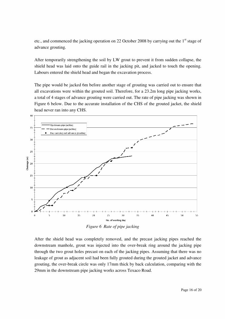
etc., and commenced the jacking operation on 22 October 2008 by carrying out the 1st stage of
advance grouting.
After temporarily strengthening the soil by LW grout to prevent it from sudden collapse, the
shield head was laid onto the guide rail in the jacking pit, and jacked to touch the opening.
Labours entered the shield head and began the excavation process.
The pipe would be jacked 6m before another stage of grouting was carried out to ensure that
all excavations were within the grouted soil. Therefore, for a 23.2m long pipe jacking works,
a total of 4 stages of advance grouting were carried out. The rate of pipe jacking was shown in
Figure 6 below. Due to the accurate installation of the CHS of the grouted jacket, the shield
head never ran into any CHS.
Figure 6 Rate of pipe jacking
After the shield head was completely removed, and the precast jacking pipes reached the
downstream manhole, grout was injected into the over-break ring around the jacking pipe
through the two grout holes precast on each of the jacking pipes. Assuming that there was no
leakage of grout as adjacent soil had been fully grouted during the grouted jacket and advance
grouting, the over-break circle was only 17mm thick by back calculation, comparing with the
29mm in the downstream pipe jacking works across Texaco Road.
Page 17 of 20
6. MONITORING AND PERFORMANCE
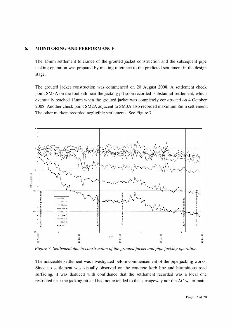
The 15mm settlement tolerance of the grouted jacket construction and the subsequent pipe
jacking operation was prepared by making reference to the predicted settlement in the design
stage.
The grouted jacket construction was commenced on 20 August 2008. A settlement check
point SM3A on the footpath near the jacking pit soon recorded substantial settlement, which
eventually reached 13mm when the grouted jacket was completely constructed on 4 October
2008. Another check point SM2A adjacent to SM3A also recorded maximum 8mm settlement.
The other markers recorded negligible settlements. See Figure 7.
Figure 7 Settlement due to construction of the grouted jacket and pipe jacking operation
The noticeable settlement was investigated before commencement of the pipe jacking works.
Since no settlement was visually observed on the concrete kerb line and bituminous road
surfacing, it was deduced with confidence that the settlement recorded was a local one
restricted near the jacking pit and had not extended to the carriageway nor the AC water main.
Page 18 of 20
The footpath where the check points SM2A and SM3A were located was covered by light
duty bricks. A crater-like settlement of the bricks around the check points and a slight tilting
parallel to the face of the adjacent 2m high concrete partition wall were observed. It was
suspected that there was localized loss of underground soil near the jacking pit, probably
brought into the jacking pit by groundwater through the local gaps in the sheet pile wall. This
was later confirmed when the jacking pit was backfilled and the sheet pile wall removed. A
cavity of around 1m3 was found under the concrete cover behind the top end of the sheet pile
wall.
The pipe jacking operation commenced on 22 October 2008 and was completed on 6
December 2008, following by the completion of over-break grouting on 15 December 2008.
Not more than 4mm settlement was recorded in all settlement check points during the whole
process. WSD also reported that no leakage was observed by their regular monitoring using
low frequency signal. The flow of the AC water main was turned back to normal operation
volume in March 2009.
Due to adopted grouted jacket and advance grouting, groundwater was blocked outside the
grouted jacket and the open end of the shield head. The amount of water seeping into the pipe
bore was negligible.
7. DISCUSSIONS
As the overburden soil strata above the pipe jacket was occupied by congested utilities, the
concept of arch effect over the jacking pipe would be less dominant, while the overburden
loading would be acting on the utility lying perpendicular to the jacking pipe alignment or the
grouted jacket which was parallel to the pipe alignment. Comparing the stiffness of individual
utilities and that of the grouted jacket, which was much higher, it was likely that the vertical
loads were resisted by the grouted jacket as a hollow tubular section. The insignificant
settlement favored this theory.
The project in overall was a success with the jacking pipe substantially completed on time
without any damage to the adjacent underground utilities.
Considering that the downstream pipe jacking works was also within the same Fill strata of
Texaco Road, it may be used as a control for the assessment on the effect and performance of
the grouted jacket. The rate of the upstream pipe jacking works which was 0.70m / working

Page 19 of 20
day was slightly faster than the downstream pipe jacking works which was 0.67m / working
day due to lack of groundwater ingress.
The volume of over-break grouting in the upstream pipe jacking works was also substantially
less than the downstream pipe jacking works, proving that over-breaking (one of the causes of
settlement) was reduced due to the soil was strengthened and compacted.
The predicted settlement for both upstream and downstream pipe jacking works was 16mm,
which was less than the 28mm and 44mm allowable by the current standard of Highways
Department. The actual maximum settlement was only 6mm (2mm by grouted jacket plus
4mm by pipe jacking operation) for the upstream pipe jacking works and 10mm for the
downstream one.
The grouted jacket is used by DSD for the first time in the drainage improvement works to
overcome the congested underground problem, it is opined that the technique can be further
refined and improved in future project.
8. CONCLUSIONS
To facilitate the smooth delivery of trenchless construction for drainage improvement works
in proximity of underground watermains, installation of grouted jacket in advance of the man-
entry pipe jacking operation can be adopted in order to reduce the risk impact to the
watermains and enhance the site safety.
Protection of adjacent delicate utilities can be done by minimizing the settlement induced by
the pipe jacking operation. The conventional ways, such as preventing work face collapse by
advance grouting and minimizing over-breaking, can in fact be supplemented by construction
of a grouted jacket around the proposed pipe jacking alignment.
The grouted jacket has the merits of confining the ground movement induced by the pipe
jacking operation within its circular body and therefore virtually isolates the utilities from the
pipe jacking operation. It can also strengthen the surrounding soil and protect the workers
working inside the pipe bore in case of water main bursting, as well as reducing groundwater
seepage into the pipe bore.
Page 20 of 20
ACKNOWLEDGEMENTS
The authors wish to express their gratitude to the Drainage Services Department of the Government
of Hong Kong SAR, for permission to extract the material from the respective project, to publish
this paper. Sincere thanks are due to Ir. W.S. Chan of Water Supplies Department for their effective
cooperation and the design team of Maurice Lee and Associates Ltd., Ir. C. T. Kumarappan and Mr.
Fiet Leung, for preparing the structural analysis. The contents of this paper do not necessarily
constitute endorsement or recommendation of the Government of Hong Kong SAR for use of
mentioned trade names and commercial products.
REFERENCES
1. Atlas Copco; “Atlas Copco Overburden drilling - the ODEX method G2”; 1999.
2. Bruce, D. A.; “Aspects of Rock Grouting Practice on British Dams”, Processing of ASCE
Conference, Grouting in Geotechnical Engineering; February 1982.
3. Dempsey, J. A. & Moller, K.; “Grouting in Ground Engineering”; 1972.
4. The Government of the Hong Kong SAR; “Geoguide 3 – Guide to Rock and Soil
Descriptions”; 1988.
5. Highways Department’s letter dated 23 May 2008 (ref.: (2B0B) in HRD 19/2/1).
6. Mair, R. J. & Taylor, R. N. & Burland, J. B.; “Prediction of ground movements and
assessment of risk of building damage due to bored tunneling”; Geotechnical Aspects of
Underground Construction in Soft Ground; 1996.
7. Mosley, W. H. & Bungey, J. H.; “Reinforced Concrete Design (4th
Edition)”; Macmillan;
1990.
8. Owen, E. K. & Tam, J. Y. C.; “Cooling seawater supply to buildings in Queensway – civil
works”, Hong Kong Engineer; HKIE; June 1989.
9. Raffle, J. F. & Greenwood, D. A.; “Relations between the rheological characteristics of grouts
and their capacity to permeate soil”, Proceedings of the 5th
International Conference of Soil
Mechanic and Foundation Engineering; 1961.
10. Water Supplies Department; “Guidelines for Excavation Near Water Mains”.
11. Xanthakos, Petros P. & Abramson, Lee W. & Bruce, Donald A.; “Ground Control and
Improvement”; 1994.