Installation Manual - University of...
16
Installation Manual 1-800-348-9843 +1-541-459-4449 www.orenco.com AdvanTex ® AX-RT Treatment Systems Residential Applications
Transcript of Installation Manual - University of...

Installation Manual
1-800-348-9843+1-541-459-4449
www.orenco.com
AdvanTex® AX-RT Treatment Systems
Residential Applications

Orenco Systems®NIM-ATX-AXRT-1Rev. 3.0, © 10/14Page 2
Installation Manual: AX-RT Treatment Systems Orenco® How To Use This Manual . . . . . . . . . . . . . . . . . . . . . . . . . . . . . . . . . . . . . . . . . . . . . . . . . . . . . . . . . . . . Page 2
Before You Begin . . . . . . . . . . . . . . . . . . . . . . . . . . . . . . . . . . . . . . . . . . . . . . . . . . . . . . . . . . . . . . . . . . Page 3
Septic Tanks Used in AX-RT Treatment Systems . . . . . . . . . . . . . . . . . . . . . . . . . . . . . . . . . . . . . . . . . . Page 3
Standard Unit Components And Functions . . . . . . . . . . . . . . . . . . . . . . . . . . . . . . . . . . . . . . . . . . . . . . Page 4
Installation Overview . . . . . . . . . . . . . . . . . . . . . . . . . . . . . . . . . . . . . . . . . . . . . . . . . . . . . . . . . . . . . . . Page 5
Installation Steps
Step 1: Review or Sketch Site Plan . . . . . . . . . . . . . . . . . . . . . . . . . . . . . . . . . . . . . . . . . . . . . . . . . . . . . . . Page 6Step 2: Perform Excavation(s) . . . . . . . . . . . . . . . . . . . . . . . . . . . . . . . . . . . . . . . . . . . . . . . . . . . . . . . . . . . Page 6Step 3: Set Septic Tank (If Needed) . . . . . . . . . . . . . . . . . . . . . . . . . . . . . . . . . . . . . . . . . . . . . . . . . . . . . . . Page 7Step 4: Set AX-RT Unit . . . . . . . . . . . . . . . . . . . . . . . . . . . . . . . . . . . . . . . . . . . . . . . . . . . . . . . . . . . . . . . . . Page 8Step 5: Install Antibuoyancy Deadmen (If Needed) . . . . . . . . . . . . . . . . . . . . . . . . . . . . . . . . . . . . . . . . . . . . Page 8Step 6: Partially Backfill Excavation(s) . . . . . . . . . . . . . . . . . . . . . . . . . . . . . . . . . . . . . . . . . . . . . . . . . . . . . Page 9Step 7: Install Adapters and Risers (If Needed). . . . . . . . . . . . . . . . . . . . . . . . . . . . . . . . . . . . . . . . . . . . . . . Page 10Step 8: Test Tank and Adapter Seams for Watertightness. . . . . . . . . . . . . . . . . . . . . . . . . . . . . . . . . . . . . . . Page 10Step 9: Test AX-RT Midseam for Watertightness . . . . . . . . . . . . . . . . . . . . . . . . . . . . . . . . . . . . . . . . . . . . . Page 11Step 10: Install Effluent Filter . . . . . . . . . . . . . . . . . . . . . . . . . . . . . . . . . . . . . . . . . . . . . . . . . . . . . . . . . . . . Page 11Step 11: Connect Tank-to-Unit Transport Line . . . . . . . . . . . . . . . . . . . . . . . . . . . . . . . . . . . . . . . . . . . . . . . . Page 11Step 12: Connect Passive Air Vent . . . . . . . . . . . . . . . . . . . . . . . . . . . . . . . . . . . . . . . . . . . . . . . . . . . . . . . . . Page 12Step 13: Connect AX-RT Outlet to Transport Line . . . . . . . . . . . . . . . . . . . . . . . . . . . . . . . . . . . . . . . . . . . . . . Page 12Step 14: Mount Control Panel and Perform Wiring . . . . . . . . . . . . . . . . . . . . . . . . . . . . . . . . . . . . . . . . . . . . . Page 12Step 15: Perform AX-RT Operational Test . . . . . . . . . . . . . . . . . . . . . . . . . . . . . . . . . . . . . . . . . . . . . . . . . . . Page 13Step 16: Complete Backfilling . . . . . . . . . . . . . . . . . . . . . . . . . . . . . . . . . . . . . . . . . . . . . . . . . . . . . . . . . . . . Page 15
How To Use This ManualThis manual contains an Installation Overview and a set of Installation Steps.
Installation Overview — This is a simple overview of the installation steps. Its purpose is to help you quickly see the suggested order of operations for installing an AX-RT unit. It is intended as a summary only — it does not provide complete instructions.
Installation Steps — This provides general instructions for each installation step along with references to detailed installation docu-ments for specific components. Many Orenco products come with installation instructions and all of these instructions are also provided in hard copy form in our Orenco Installer Binder. Contact your Dealer or Orenco for a copy of the binder, or find individual instructions online in the Orenco Document Library at www.orenco.com. There are also steps in this manual covering operations performed before and after the AX-RT unit is installed that are necessary to successfully complete the installation.
You will find IMPORTANT information, Key Points, and Notes in this manual, marked with easy-to-see visuals:
IMPORTANT — These point out potential hazards to equipment or people during and after the installation.
Key Points — These are critical for a quality installation and must be completed in order for your installation to be successful.
Notes — These cover useful information and tips that can help make your installation simpler or easier. They may also provide information on variations in components or methods.

Orenco Systems® NIM-ATX-AXRT-1Rev. 3.0, © 10/14
Page 3
Installation Manual: AX-RT Treatment Systems Orenco®
Before You BeginAt Orenco, we work hard to make your installation as easy and “hassle-free” as possible. This manual provides basic information for installing AdvanTex AX-RT™ treatment units. It is not intended to replace installer training or requirements and instructions detailed in your engineering plans. If you discover any inconsistencies between your engineering plans and the instructions in this manual, contact your engineer or call your AdvanTex Dealer. If you are not an Authorized AdvanTex Installer, contact your local AdvanTex Dealer for training and authorization before installing this system.
The Dealer can provide technical support, training, and replacement components. To find the nearest Dealer, check the Distributor Locator page at www.orenco.com. If there is no Dealer in your area, call Orenco Systems, Inc. at (800) 348-9843 or +1 (541) 459-4449.
Before you begin this installation, read this entire manual and any reference documents you may need to be familiar with to complete the installation. Also, be sure that the instructions for these products are the most current ones available. Please note that you must perform the installation according to the current manual or the AdvanTex® Treatment Systems Limited Warranty will be void. You can make sure your instructions are current by checking our online Document Library at www.orenco.com. You’ll save time and money on installation day, and you’ll get fewer call-backs.
Key Point: Inspect your order for completeness and inspect each component for shipping damage. Check to be sure instructions and items supplied comply with your state and local regulations. Carefully read and follow all instructions. Improper installation may void warranties.
IMPORTANT: The backwash discharge from a salt-type water softener MUST NOT be plumbed into an AX-RT Treatment Unit or the preceding septic tank. Failure to follow this instruction, or any other in this manual, will void the system’s warranty. Contact your AdvanTex Dealer if you have any questions about any household plumbing arrangements that may interfere with the functioning of the system.
Note: All pipe diameters provided are U.S. nominal PVC pipe sizes. If you are using metric pipe, you may need adapters to connect to the U.S. fittings supplied with AdvanTex Treatment Systems.
Septic Tanks Used in AX-RT Treatment SystemsBe sure that any septic tank used in an AX-RT Treatment System meets the following conditions:
The tank must conform to an approved and authorized tank design for AdvanTex Systems, and it must meet all applicable regula-tory requirements (no pour-in-place tanks, no homemade tanks, etc.). Call your local Dealer for specifics.
The tank must be structurally sound.
The tank must have at least 1000 gal. (3800 L) capacity for an AX20-RT, 1250 gal. (4730 L) for a 5-bedroom AX25-RT, and 1500 gal. (5680 L) for a 6-bedroom AX25-RT at the normal operating level (below the invert of the outlet).
The tank must have an at-grade access with a watertight, securable and removable lid. If it doesn’t, an at-grade access must be installed onto the septic tank and be made watertight.
The tank must be watertight and free of leaks.
An Orenco effluent filter (model FTS0444-36V, FTW0444-36V, or FT0822-14B) must be installed in the septic tank.
Key Point: For existing septic tanks — the tank’s depth of burial must allow for a minimum fall of 1⁄8 inch per foot (10 mm per meter or 1%) from the septic tank’s invert of outlet to the AX-RT unit’s invert of the inlet. If sufficient fall cannot be met, a grade ring extension must be installed on the AX-RT or a pumping system will need to be installed in the septic tank to move the filtered effluent to the AX-RT unit. (Contact your Dealer for assistance.)
Orenco Systems®NIM-ATX-AXRT-1Rev. 3.0, © 10/14Page 4
Installation Manual: AX-RT Treatment Systems Orenco®
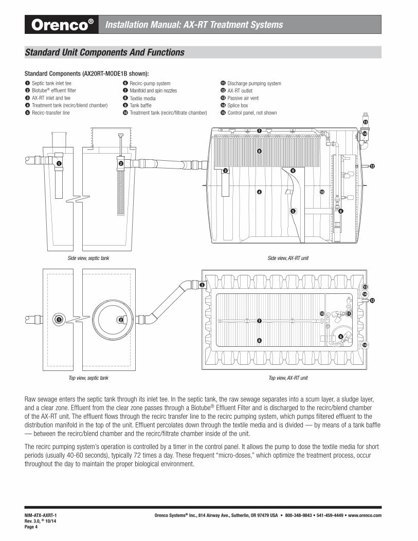
Standard Unit Components And Functions
Raw sewage enters the septic tank through its inlet tee. In the septic tank, the raw sewage separates into a scum layer, a sludge layer, and a clear zone. Effluent from the clear zone passes through a Biotube® Effluent Filter and is discharged to the recirc/blend chamber of the AX-RT unit. The effluent flows through the recirc transfer line to the recirc pumping system, which pumps filtered effluent to the distribution manifold in the top of the unit. Effluent percolates down through the textile media and is divided — by means of a tank baffle — between the recirc/blend chamber and the recirc/filtrate chamber inside of the unit.
The recirc pumping system’s operation is controlled by a timer in the control panel. It allows the pump to dose the textile media for short periods (usually 40-60 seconds), typically 72 times a day. These frequent “micro-doses,” which optimize the treatment process, occur throughout the day to maintain the proper biological environment.
1
1 2
3
3
4
5
9
7
8
6
2
6
7
8
10 11
12
12
13
13
14
14
14
10
Side view, septic tank
Top view, septic tank
Side view, AX-RT unit
Top view, AX-RT unit
Standard Components (AX20RT-MODE1B shown):
3
1
4
5
2
Septic tank inlet teeBiotube® effluent filterAX-RT inlet and teeTreatment tank (recirc/blend chamber)Recirc-transfer line
8
6
9
10
7
Tank baffleTreatment tank (recirc/filtrate chamber)
Recirc-pump system
Textile mediaManifold and spin nozzles
13
11
14
15
12
Discharge pumping system AX-RT outletPassive air ventSplice boxControl panel, not shown

Orenco Systems® NIM-ATX-AXRT-1Rev. 3.0, © 10/14
Page 5
Installation Manual: AX-RT Treatment Systems Orenco®
Installation OverviewStep 1: Review the site plan. If there is no site plan, draw up a plan including locations and distances.
Step 2: Perform the excavations for the AX-RT unit and (if needed) the septic tank.
Step 3: If the septic tank has not been set, set it according to the manufacturer’s instructions.
Step 4: Set the AX-RT unit.
Step 5: Install antibuoyancy deadmen on the AX-RT unit (if needed).
Step 6: Partially backfill the AX-RT unit and (if needed) the septic tank.
Step 7: If the tank adapters and risers have not been installed on the septic tank, install them according to the manufacturer’s instructions.
Step 8: If no watertightness test has been performed on the tank and the tank-to-riser connections, perform a watertightness test.
Key Point: The tank and tank-to-riser connections must pass this test before the AX-RT is connected to the tank.
Step 9: Perform a watertightness test of the AX-RT unit’s midseam.
Step 10: If the effluent filter has not been installed in the septic tank, install it according to the manufacturer’s instructions.
Step 11: Connect the transport line from the septic tank outlet to the AX-RT unit.
Step 12: Connect the passive air vent to the AX-RT unit.
Step 13: Connect the discharge line to the AX-RT outlet.
Step 14: Install and test the control panel and wiring for the AX-RT unit.
Step 15: Perform an operational test of the AX-RT float switches and pump(s).
Step 16: Complete the backfilling of the AX-RT unit and (if needed) the septic tank.
Orenco Systems®NIM-ATX-AXRT-1Rev. 3.0, © 10/14Page 6
Installation Manual: AX-RT Treatment Systems Orenco®
Installation Steps
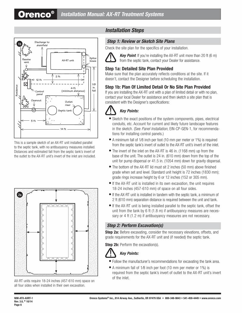
Step 1: Review or Sketch Site PlansCheck the site plan for the specifics of your installation.
Key Point: If you’re installing the AX-RT unit more than 20 ft (6 m) from the septic tank, contact your Dealer for assistance.
Step 1a: Detailed Site Plan Provided Make sure that the plan accurately reflects conditions at the site. If it doesn’t, contact the Designer before scheduling the installation.
Step 1b: Plan Of Limited Detail Or No Site Plan ProvidedIf you are installing the AX-RT unit with a plan of limited detail or with no plan, contact your local Dealer for assistance and then sketch a site plan that is consistent with the Designer’s specifications:
Key Points:
Sketch the exact positions of the system components, pipes, electrical conduits, etc. Account for current and likely future landscape features in the sketch. (See Panel Installation, EIN-CP-GEN-1, for recommenda-tions for installing control panels.) A minimum fall of 1⁄8 inch per foot (10 mm per meter or 1%) is required from the septic tank’s invert of outlet to the AX-RT unit’s invert of the inlet. The invert of the inlet on the AX-RT is 46 in. (1168 mm) up from the base of the unit. The outlet is 24 in. (610 mm) down from the top of the unit for pump dispersal or 41.5 in. (1054 mm) down for gravity dispersal. The bottom of the AX-RT lid must sit 2 inches (50 mm) above finished grade when set and level. Standard unit height is 72 inches (1830 mm); grade rings increase height by 6 or 12 inches (152 or 305 mm). If the AX-RT unit is installed in its own excavation, the unit requires 18-24 inches (457-610 mm) of space on all four sides. If the AX-RT unit is installed in tandem with the septic tank, a minimum of 2 ft (610 mm) separation distance is required between the unit and tank. If the AX-RT unit is being installed parallel to the septic tank, offset the unit from the tank by 6 ft (1.8 m) if antibuoyancy measures are neces-sary or 4 ft (1.2 m) if antibuoyancy measures are not necessary.
Step 2: Perform Excavation(s)Step 2a: Before excavating, consider the necessary elevations, offsets, and grade requirements for the AX-RT unit and (if needed) the septic tank.
Step 2b: Perform the excavation(s).
Key Points:
Follow the manufacturer’s recommendations for excavating the tank area.
A minimum fall of 1⁄8 inch per foot (10 mm per meter or 1%) is required from the septic tank’s invert of outlet to the AX-RT unit’s invert of the inlet.
2a
AX-RT units require 18-24 inches (457-610 mm) space on all four sides when installed in their own excavation.
This is a sample sketch of an AX-RT unit installed parallel to the septic tank, with no antibuoyancy measures installed. Distances and estimated fall from the septic tank’s invert of the outlet to the AX-RT unit’s invert of the inlet are included.
Cleanout
Control panelRe
side
nce
Septic tank
Outlet riser
AX-RT unitPassive vent
Discharge to drainfield1b
4-ft (minimum distance)
12 ft 1/8 in. fall
2 ft
5 ft
14 ft
Splice boxes

Orenco Systems® NIM-ATX-AXRT-1Rev. 3.0, © 10/14
Page 7
Installation Manual: AX-RT Treatment Systems Orenco®
Make sure the excavation is stable, smooth, level, and free from debris, rocks, and sharp objects.
2c
Installation Steps
Step 2: Perform Excavation(s), cont.Step 2c: Make sure the bottom of the excavation is suitable for setting the AX-RT unit and (if needed) the tank: stable, smooth, level, and free of debris, rocks, and other sharp objects.
Key Points:
Follow the manufacturer’s instructions for bedding the tank.
If the bottom of the excavation is uneven or rocky, lay a 4-in. (100-mm) bed of sand or pea gravel and compact the material to create an even, smooth surface.
Step 2d: If the bottom of the excavation is unstable, stabilize the bottom of the excavation before continuing.
For unstable base soil (peat, quicksand, muck, soft or highly expansive clay, etc.), you may need to over-excavate the site depth and set a firm, 6-in. (152-mm) compacted base of ) ½- to ) ¾-in. (13- to 19-mm) aggregate or pea gravel. For extremely unstable soil, you may need to pour a concrete layer to stabilize the bottom of the excavation. If you have doubt about the soil’s stability, consult a local civil or struc-tural engineer.
Step 3: Set Septic Tank (If Needed)Set the septic tank according to the manufacturer’s instructions.
Use Fiberglass Tank Burial instructions (NIN-TNK-1) to install Orenco’s 500-gallon through 2000-gallon (2000-L through 7570-L) Fiberglass Tanks.
IMPORTANT: Take care to keep everyone clear of the excavation when placing the tank.
Key Points:
The tank has to be set at the correct depth to connect to the sewage inlet.
A minimum fall of 1⁄8 inch per foot (10 mm per meter or 1%) is required from the septic tank’s invert of outlet to the AX-RT unit’s invert of the inlet.

Orenco Systems®NIM-ATX-AXRT-1Rev. 3.0, © 10/14Page 8
Installation Manual: AX-RT Treatment Systems Orenco®
Installation Steps
Step 4: Set AX-RT UnitStep 4a: Attach proper lifting equipment to the lifting points on the AX-RT unit.
Step 4b: Carefully lift the unit and lower it into the correct position.
Step 4c: Remove the equipment when the unit is set and level in position.
IMPORTANT: Take care to keep everyone clear of the excavation when placing the unit. Use a lifting device that will not damage the unit or the unit’s lid.
Key Points:
A minimum fall of 1⁄8 inch per foot (10 mm per meter or 1%) is required from the septic tank’s invert of outlet to the AX-RT unit’s invert of the inlet. The bottom of the AX-RT lid must sit 2 inches (50 mm) above finished grade when set and level. If the AX-RT unit is installed in its own excavation, the unit requires 18-24 inches (457-610 mm) of space on all four sides. If the AX-RT unit is installed in tandem with the septic tank, a minimum of 2 ft (610 mm) separation distance is required between the unit and tank. If the AX-RT unit is being installed parallel to the septic tank, offset the unit from the tank by 6 ft (1.8 m) if antibuoyancy measures are neces-sary or 4 ft (1.2 m) if antibuoyancy measures are not necessary.
Step 5: Install Antibuoyancy Deadmen (If Needed)Determine if antibuoyancy deadmen are necessary for the installation. Orenco offers antibuoyancy hardware kits that can be used with Orenco fiberglass deadmen or concrete deadmen.
Deadmen are recommended for all installations.
Deadmen are required if there is a potential for groundwater to be pres-ent in the excavation at any time, or if surface runoff can fill the excava-tion at any time, resulting in a “bathtub” effect.
Note: This effect occurs in dense soils when water fills an excavation during surface water runoff —usually during a heavy rain event — before the disturbed soil in the excavation has had time to settle.
If you are unsure whether to install antibuoyancy deadmen or not, con-sult the system Designer or an engineer.
Step 5a: Installing Orenco Fiberglass DeadmenStep 5a (i): Build up a 3- to 4-inch (75- to 100-mm) lift of soil on each side of the unit for the deadmen to rest upon.
Step 5a (ii): Secure the deadmen along the length of the unit, on both sides, with the antibuoyancy kit hardware. Then lower the unit into the hole.
Step 5a (iii): Place the deadmen at least 12 inches (300 mm) from the bottom of the unit, and make sure they are level.
4b
When using Orenco fiberglass deadmen, be sure to place them on a small lift of soil 12 inches (300 mm) from the bottom of the AX-RT.
Lower the AX-RT unit into position.
5a
18-24 in. (460-600 mm)
12 in. (300 mm)

Orenco Systems® NIM-ATX-AXRT-1Rev. 3.0, © 10/14
Page 9
Installation Manual: AX-RT Treatment Systems Orenco®
Installation Steps
Step 5: Install Antibuoyancy Deadmen (If Needed), cont. Step 5b: Installing Concrete Deadmen
Notes:
We recommend preparing concrete deadmen off site before installation.
PVC forms for concrete deadmen can be made from 12-in. dia. × 4-ft long (300-mm × 1200-mm long) PVC half-pipe or chamber material.
Wooden forms for concrete deadmen can be built 12-in. wide × 6 in. tall × 4 ft long (300-mm × 150-mm × 1200-mm).
Step 5b (i): Fill two forms halfway with concrete.
Step 5b (ii): Place two #4 reinforcing bars in each of the forms.
Step 5b (iii): Finish filling the forms.
Step 5b (iv): Sink eyebolts from the antibuoyancy hardware kit into the concrete for attaching the deadmen later.
Step 5b (v): Let the concrete set completely before moving the deadmen.
Step 5b (vi): Use appropriate lifting gear to set the deadmen in place.
Step 5b (vii): Secure the deadmen along the length of the unit, on both sides, with the antibuoyancy hardware kit and make sure they are level.
Step 6: Partially Backfill Excavation(s)Partially backfill around the AX-RT unit and (if needed) the tank. Follow the manufacturer’s instructions for backfilling around the tank. Follow the steps below to backfill around the AX-RT unit.
IMPORTANT: Bolt down the AX-RT lid before backfilling! Bolting down the lid increases rigidity and helps prevent deformation.
Step 6a: Fill the AX-RT with 16 in. (410 mm) of water on both sides of the baffle.
Step 6b: Backfill around the unit with a 16-inch (410-mm) layer of material.
Key Points:
Do not use native material to backfill if it is primarily sand; very soft or highly expansive clay; or if it contains debris, large (> ¾-in. or 19-mm) rocks, sharp rocks, peat, or muck. In these cases, use ) ¾ inch () 19 mm) rounded gravel, crushed stone, or pea gravel as fill material. This material should be washed, free-flowing, and free of debris. Do not backfill with sand.
Step 6c: Compact the fill thoroughly with a mechanical compactor.
Step 6d: Fill the AX-RT with water to just above the midseam flange on both sides of the baffle.
Step 6e: Add another 16-inch (410-mm) layer of backfill.
Step 6f: Compact the fill to 2-3 inches (50-75 mm) below the midseam flange.
IMPORTANT: Do not backfill around the unit unless the lid is bolted down!
6

Orenco Systems®NIM-ATX-AXRT-1Rev. 3.0, © 10/14Page 10
Installation Manual: AX-RT Treatment Systems Orenco®
Installation Steps
Step 7: Install Adapters and Risers (If Needed)Step 7a: Install tank adapters if needed. Follow the manufacturer’s instructions.
Use PRTA24 and PRTA30 Tank Adapter Installation (NIN-TA-PRTA-2) instructions for installing Orenco PRTA24 or PRTA30 Tank Adapters.
Use RRFTA and RRFTA30 Tank Adapter Installation (NIN-TA-RRFTA-1) instructions for installing Orenco RRFTA or RRFTA30 Tank Adapters.
Use FRTA30-FRP Tank Adapter Installation (NIN-TA-FRTA-1) instructions for installing Orenco FRTA30-FRP Tank Adapters.
Use Tank Adapter Installation for Roth Tanks (NIN-TA-RR-2) instructions for installing Orenco FRTA24-R or Orenco PRTA30 Tank Adapters on Roth Fralo tanks.
Step 7b: Install the access risers and any necessary grommets.
Use PVC Access Riser Installation (NIN-RLA-RR-1) instructions for installing access risers on Orenco Tank Adapters and grommets in access risers.
Key Points:
The seam between the tank and the tank adapter has to be watertight.
Watertight seams and penetrations are critical for proper performance.
Before installing the riser, make sure the riser is the correct height — the recommended riser height is 2-3 inches (50-75 mm) above final grade.
Before installing the riser, make sure that the riser penetrations are made at the correct height to make connections.
Before installing the riser, make sure the penetrations are aligned correctly.
After installing the riser, make sure all adhesive seams are free of voids, with smooth, continuous fillets.
After installing the riser, make sure the adhesive is set before continuing.
Step 8: Test Tank and Adapter Seams For WatertightnessStep 8a: Test the tank for watertightness if it has not been tested already.
Note: Follow the manufacturer’s recommendations for watertight-ness testing. Some manufacturers require the tank be fully backfilled before testing watertightness.
Step 8b: Test the tank-to-riser adapter seams for watertightness.
Use PVC Access Riser Installation (NIN-RLA-RR-1) instructions to test the seams between the access riser, tank adapter, and tank for watertightness.
Key Points:
Watertight seams are critical for proper system performance — the seams between the access riser, tank adapter, and tank must all pass the water-tightness test before you continue.
Follow all applicable regulations and manufacturer’s instructions for water-tightness testing.
See Orenco’s PVC Access Riser Installation (NIN-RLA-RR-1) instructions for installing access risers on Orenco Tank Adapters.
Watertight seams are critical for proper performance.
7b
7b

Orenco Systems® NIM-ATX-AXRT-1Rev. 3.0, © 10/14
Page 11
Installation Manual: AX-RT Treatment Systems Orenco®
Fill AX-RT unit with water to 1-2 inches (25-50-mm) above the midseam flange on both sides of the baffle.
9a
Installation Steps
Step 9: Test AX-RT Midseam for WatertightnessStep 9a: Make sure the AX-RT unit is filled with water to 1-2 inches (25-50 mm) above the midseam flange on both sides of the tank baffle.
Step 9b: Wait 15 minutes and then inspect the midseam flange for leaks. There should be no drop in liquid level and no visible leakage from the seam.
Step 9c: If there is any leakage, contact your Dealer for information on repairing the AX-RT unit.
Step 10: Install Effluent FilterInstall the effluent filter after the tank has been water tested.
Step 10a: Verify the model of the effluent filter.
Orenco’s FTS0444-36V, FTW0444-36V, and FT0822-14B filters are the only models allowed for use with the AX-RT Treatment Unit.
Step 10b: Dry test-fit the effluent filter on the septic tank’s outlet pipe.
Key Points:
Make sure the filter is plumb.
Make sure the filter is snug to the tank wall with enough clearance for easy removal of the filter cartridge.
Step 10c: Secure the filter to the outlet pipe with one of the following methods:
Glue the filter onto the tank outlet pipe with primer and glue, or
Secure the filter with a stainless steel set screw.
Step 10d: If necessary for ease of access, extend the cartridge handle with a longer length of ¾-inch nominal (20-mm DN) Schedule 40 PVC pipe.
Step 11: Connect Transport Line from Tank to AX-RTStep 11a: Dry fit the 4-inch (100-mm) transport line and any fittings between the outlet of the septic tank and the inlet of the AX-RT unit.
Key Point: Confirm there is a minimum fall of 1⁄8 inch per ft (10 mm per m or 1%) from the septic tank’s invert of outlet to the AX-RT unit’s invert of the inlet.
Step 11b: Glue all of the transport line pieces in place.
IMPORTANT: Do not use primer on ABS parts.
Effluent filter installed on the septic tank outlet.
Confirm a minimum fall of 1⁄8 inch per foot (10 mm per meter or 1%) from the septic tank’s invert of outlet to the AX-RT unit’s invert of the inlet.
10
11
1/8 inch minimum fall

Orenco Systems®NIM-ATX-AXRT-1Rev. 3.0, © 10/14Page 12
Installation Manual: AX-RT Treatment Systems Orenco®
Installation Steps
Step 12: Connect Passive Air VentUse 2-inch (50 mm) PVC pipe to plumb the passive air vent to the 2-inch (50 mm) vent fitting that protrudes from the outlet side of the AX-RT unit.
Key Points:
Install the vent within 20 ft (6 m) of the AX-RT unit, preferably near a wall or other location that will protect it from damage.
Make sure the vent line is sloped back a minimum of ¼ inch per foot (20 mm per meter) so that it can drain back into the unit.
Make sure there are no “bellies” in the line that can collect water.
Make sure the vent’s top is a minimum of 3 in. (75 mm) above final grade.
Notes:
The air vent can easily be hidden by shrubbery or landscaping.
The air vent can be painted to better blend in with landscaping.
Step 13: Connect AX-RT Outlet to Transport LineGlue the AX-RT discharge plumbing line to the transport line for final discharge.
Step 14: Mount Control Panel and Perform Wiring
Key Points:
This step should be performed by a licensed or qualified electrician.
Installation instructions, schematics, and wiring diagrams specific to the panel and float switch configuration are included with each panel. If any of these is missing, contact your Dealer or Orenco for a replacement.
Step 14a: Install the splice box(es) on the AX-RT using the instructions that came with it.
Step 14b: Mount the panel using the instructions that came with it.
IMPORTANT: DO NOT mount the control panel on an exterior wall other than a garage or shop wall! The motor contactor makes a sound while engaging and disengaging that can be disruptive to residents.
Key Points:
Follow all applicable regulations for placement of the control panel.
Mount the panel within sight of the tank in a service-friendly location.
14b
Wire control panel.
Install the vent within 20 ft (6 m) of the AX-RT unit.
12
Passive air vent

Orenco Systems® NIM-ATX-AXRT-1Rev. 3.0, © 10/14
Page 13
Installation Manual: AX-RT Treatment Systems Orenco®
Installation Steps
Step 14: Mount Control Panel and Perform Wiring, cont.Step 14c: Route wires and connect the panel, pump, float switches, and other equipment shown in the instructions and schematics into the control panel.
IMPORTANT: Follow all applicable regulations and electric codes.
Key Points:
Use watertight wire connectors to avoid electrical shorts and other issues.
Be sure to seal the conduit at the control panel and at the splice box with UL-listed sealing foam, putty, or silicone sealant.
Note: To help identify wiring runs for individual pumps and float switches, use different-colored wires for each electrical component.
Step 15: Perform AX-RT Operational Test
IMPORTANT: Before using a generator to operate a pump, contact your Dealer or Orenco to make sure it can supply sufficient starting amperage to the pump.
Step 15a: Rotate the manifold so that the spin nozzles face upward.
Step 15b: Remove the cap at the end of the manifold.
Step 15c: Toggle the recirc pump “AUTO/OFF/MAN” switch to “MAN” for 10-20 seconds to flush any debris out of the manifold.
IMPORTANT: Always make sure there is enough water in the AX-RT’s recirc/blend chamber to safely run the pump.
Step 15d: Rotate the manifold so that the spin nozzle faces down and reinstall the cap on the end of the manifold.
Step 15e: Install the pressure gauge on the manifold.
Step 15f: Toggle the recirc pump “AUTO/OFF/MAN” switch to “MAN” and adjust the gate valve for a pressure gauge reading of 3.0-3.5 psi (20.7-24.1 kPa).
Note: If the manifold won’t pressurize to 3.0-3.5 psi (20.7-24.1 kPa), check for debris, line breaks, or broken valves, and verify that the pump has sufficient power. Contact your Dealer for additional assistance.
Key Point: Check for complete spray coverage of the textile media and adjust the pressure as needed for complete coverage.
Step 15g: Toggle the recirc pump “AUTO/OFF/MAN” switch to “OFF.”
Step 15h: Remove the pressure gauge.
Step 15i: Return the recirc pump “AUTO/OFF/MAN” switch to “AUTO.”
15a
15e
Install pressure gauge
Adjust gate valve
15f
Rotate the manifold so spin nozzles face upward.
15b
Remove the cap at the end of the manifold.

Orenco Systems®NIM-ATX-AXRT-1Rev. 3.0, © 10/14Page 14
Installation Manual: AX-RT Treatment Systems Orenco®
Installation Steps
Step 15: Perform AX-RT Operational Test, cont.Step 15j: If the system uses a VCOM™ control panel, use the instructions that came with it to place the control panel in “Test Mode.” If the system uses an MVP control panel, go on to the next step.
Step 15k: Check the operation of the recirc chamber’s float switches by raising and lowering the low-level, mid-level, and high-level float in turn and verifying that each performs its intended function.
If the AX-RT unit has a discharge pump, continue to step 15l. If the AX-RT unit has an MVP panel and gravity discharge, go to step 15o.
If the AX-RT has a VCOM panel and gravity discharge, take the panel out of “Test Mode” and go to step 15o.
IMPORTANT: Always make sure there is enough water in the AX-RT’s discharge chamber to safely run the pump.
Step 15l: Toggle the discharge pump’s “AUTO/OFF/MAN” switch to “MAN” and verify the pump runs.
Step 15m: Toggle the discharge pump’s “AUTO/OFF/MAN” switch to “AUTO.”
Step 15n: Check the operation of the discharge chamber’s float switches by raising and lowering the low-level, mid-level, and high-level float in turn and verifying that each performs its intended function.
For units with a VCOM control panel, take the control panel out of “Test Mode.”
Step 15o: Make sure the recirc pump and (if equipped) discharge pump’s “AUTO/OFF/MAN” switches are toggled to “AUTO.”
Step 15p: Close and bolt down the lid on the AX-RT unit.

Orenco Systems® NIM-ATX-AXRT-1Rev. 3.0, © 10/14
Page 15
Installation Manual: AX-RT Treatment Systems Orenco®
Installation Steps
Step 16: Complete Backfilling
Key Points:
When backfilling, be careful not to alter the slope of pipes. Brace the pipes or place the pipes on a compacted bed and carefully fill around them.
Before backfilling, make sure the AX-RT unit’s lid and all riser lids are bolted down.
Step 16a: Backfill the septic tank excavation if it has not yet been done. Follow the tank manufacturer’s guidelines for backfilling.
Step16b: Backfill and compact around the AX-RT unit in maximum 12-inch (305-mm) lifts.
Key Points:
Do not use native material to backfill if it is primarily sand; very soft or highly expansive clay; or if it contains debris, large (> ¾-in. or 19-mm) rocks, sharp rocks, peat, or muck. In these cases, use ) ¾-in. () 19 mm) rounded gravel, crushed stone, or pea gravel as fill material. This material should be washed, free-flowing, and free of debris.
For installations in non-cohesive soils* with high seasonal water tables, use ¾-inch crushed rock as the backfill material.
Do not backfill with sand.
Step 16c: Compact the fill thoroughly with a mechanical compactor.
Key Points:
The bottom of the AX-RT lid should sit 2 inches (50 mm) above final grade. After backfilling, call the system’s Service Provider to arrange for the official System Start-up.
Step 16d: Be sure the AX-RT unit’s lid is closed and secured.
Step 16e: Be sure the septic tank’s access lids are secured.
16b
Backfill the AX-RT in 12-inch (300 mm) lifts.
Maintain minimum 1/8 in. (10 mm or 1%) slope
2 in. (50 mm) above final grade
* As described in OSHA Standards (29 CFR, Part 1926, Subpart P, Appendix A), noncohesive soils or granular soils include gravel, sand, or silt with little or no clay content. Granular soil cannot be molded when moist and crumbles easily when dry. Cohesive soils include clayey silt, sandy clay, silty clay, clay, and organic clay. Cohesive soil does not crumble, can be excavated with vertical sideslopes, is hard to break up when dry, and when moist, can be rolled into threads without crumbling. For example, if at least a 2-inch (51-mm) length of 1/8-inch (3-mm) thread can be held on one end without tearing, the soil is cohesive.

1-800-348-9843+1-541-459-4449www.orenco.com
NIM-ATX-AXRT-1Rev. 3.0, © 10/14Orenco Systems®, Inc.
Installation Manual
AdvanTex® AX-RT Treatment SystemsResidential Applications
NSF/ANSI STANDARD 40
NSF®
AdvanTex Treatment System AX-RTN Models meet the requirements of NSF/ANSI Standard 40 for Class I Systems.