
Installation manual - Schaffner · Always connect the filter to protective earth (PE) ......
25
Installation Manual Passive Harmonic Filters Schaffner Group | Nordstrasse 11 | 4542 Luterbach | Switzerland T +41 32 681 66 26 | F+ 41 32 681 66 30 | www.schaffner.com ECOsine ® High-power Line Enclosed
Transcript of Installation manual - Schaffner · Always connect the filter to protective earth (PE) ......

Installation Manual Passive Harmonic Filters
Schaffner Group | Nordstrasse 11 | 4542 Luterbach | Switzerland
T +41 32 681 66 26 | F+ 41 32 681 66 30 | www.schaffner.com
ECOsine® High-power Line Enclosed

Schaffner Group
Installation Manual
ECOsine®
High-power Line Enclosed (200…400kW, 300…500HP)
August 2015
210/25
INS_157018A
Important user notice
Schaffner ECOsine®
harmonic filters are designed for the operation on the input (grid) side of power
electronic equipment with 6-pulse rectifier front ends in balanced three-phase power systems, like
typically used in AC or DC motor drives and high power DC supplies. Filter suitability for a given
application must be determined by the user (the party that is putting the filter into operation) on a case by
case basis. Schaffner will not assume liability for any consequential downtimes or damages resulting
from use or application of ECOsine®
filters outside of their specifications.
February 2016
Important safety notes
Filter installation, start-up, operation and maintenance has to be carried out by a trained and
certified electrician or technician, who is familiar with safety procedures in electrical systems.
High voltage potentials are involved in the operation of this product. Always remove power
before handling energized parts of the filter, and let ample time elapse for the capacitors to
discharge to safe levels (<42V). Residual voltages are to be measured both line to line and
line to earth.
Always connect the filter to protective earth (PE) first, then continue with the wiring phase
terminals. When decommissioning the filter, remove the PE connection at the end.
Follow the installation notes closely. Ensure sufficient forced cooling as outlined in this
documentation. Operate the filter within its electrical, mechanical, thermal and ambient
specifications at all times.
Passive harmonic filters are lossy electrical components. Filter surfaces and terminals may
get hot under full load operating conditions.
Always practice the safety procedures defined by your company and by applicable national
electric codes when handling, installing, operating or maintaining electrical equipment.
Do not operate ECOsine®
filters on unsymmetrical loads, on linear loads, or with single-
phase equipment.
Always use an upstream disconnect or protection device as required by most national and
international electric codes and safety standards.
Follow the Schaffner instructions closely when doing maintenance work. Use exclusively
spare parts recommended and approved by Schaffner.
In case of uncertainty and questions please don’t hesitate to contact your local authorized
Schaffner partner or Schaffner sales office for assistance.
Schaffner Group
Installation Manual
ECOsine®
High-power Line Enclosed (200…400kW, 300…500HP)
August 2015
310/25
INS_157018A
Content
1. Part number coding ............................................................................................................................ 4
2. Scope of delivery ................................................................................................................................. 5
3. Filter specifications ............................................................................................................................. 7
3.1 GENERAL ELECTRICAL SPECIFICATIONS FN3410 AND FN3411 (50HZ FILTERS) ....................................... 7
3.2 GENERAL ELECTRICAL SPECIFICATIONS FN3412 AND FN3413 (60HZ FILTERS) ....................................... 8
3.3 ADDITIONAL SPECIFICATIONS ................................................................................................................. 9
4. Schematic .......................................................................................................................................... 10
5. Filter installation ................................................................................................................................ 11
5.1 VISUAL INSPECTION ........................................................................................................................... 11
5.2 PROTECTION DEGREE IP54/NEMA12 ................................................................................................ 13
5.3 REQUIRED INSTALLATION PROCEDURE ................................................................................................. 14
5.4 DIMENSIONS OF FILTER CABINETS ........................................................................................................ 19
5.5 FURTHER INSTALLATION INSTRUCTIONS ............................................................................................... 21
5.5.1 CONNECT OVER-TEMPERATURE SWITCH (TERMINALS 1 AND 2) .......................................................... 21
5.5.2 ADDITIONAL THERMAL MONITORING SENSORS (TERMINALS 3/4 AND 5/6) ............................................ 21
5.6 INSTALLATION OF FUSES ..................................................................................................................... 22
6. Filter maintenance ............................................................................................................................. 23
6.1 MAINTENANCE SCHEDULE ................................................................................................................... 23
6.2 FAN AND AIR FILTER ............................................................................................................................ 23
6.3 POWER CAPACITORS .......................................................................................................................... 24
6.4 ELECTRICAL CONNECTIONS ................................................................................................................. 24

Schaffner Group
Installation Manual
ECOsine®
High-power Line Enclosed (200…400kW, 300…500HP)
August 2015
410/25
INS_157018A
1. Part number coding
FN 341x-xxx-xx-xy
Functional options (for packaging option “E” only):
2 = IP23
5 = IP54
Packaging options:
E = Enclosed filter IP23 or IP54; bottom cable entry
O = open panel filter modules
C = component kit L & C
Input/output connection style:
99 = copper bus bar terminals
Typical unfiltered drive input current [Arms]
Filter family
3410 = filter for 50Hz, 380-500V grids, diode rectifiers
3411 = filter for 50Hz, 380-500V grids, SCR rectifiers
3412 = filter for 60Hz, 380-480V grids, diode rectifiers
3413 = filter for 60Hz, 380-480V grids, SCR rectifiers
Schaffner standard filter range
Note: this document only refers to cabinet version. Options in grey color (above) are not available for
this product version.

Schaffner Group
Installation Manual
ECOsine®
High-power Line Enclosed (200…400kW, 300…500HP)
August 2015
510/25
INS_157018A
2. Scope of delivery
Table 1 Filter family with protection degree IP23
Product Code
Freq. in Hz
Application
Power in kW
Power in HP
Protection degree
FN 3410-380-99-E2 50 Diode 200 IP23
FN 3410-470-99-E2 50 Diode 250 IP23
FN 3410-580-99-E2 50 Diode 315 IP23
FN 3410-650-99-E2 50 Diode 355 IP23
FN 3410-710-99-E2 50 Diode 400 IP23
FN 3411-380-99-E2 50 SCR 200 IP23
FN 3411-470-99-E2 50 SCR 250 IP23
FN 3411-580-99-E2 50 SCR 315 IP23
FN 3411-650-99-E2 50 SCR 355 IP23
FN 3411-710-99-E2 50 SCR 400 IP23
FN 3412-380-99-E2 60 Diode 300 IP23
FN 3412-440-99-E2 60 Diode 350 IP23
FN 3412-490-99-E2 60 Diode 400 IP23
FN 3412-540-99-E2 60 Diode 450 IP23
FN 3412-590-99-E2 60 Diode 500 IP23
FN 3413-380-99-E2 60 SCR 300 IP23
FN 3413-440-99-E2 60 SCR 350 IP23
FN 3413-490-99-E2 60 SCR 400 IP23
FN 3413-540-99-E2 60 SCR 450 IP23
FN 3413-590-99-E2 60 SCR 500 IP23

Schaffner Group
Installation Manual
ECOsine®
High-power Line Enclosed (200…400kW, 300…500HP)
August 2015
610/25
INS_157018A
Table 2 Filter family with protection degree IP54
Product Code
Freq. in Hz
Application
Power in kW
Power in HP
Protection degree
FN 3410-380-99-E5 50 Diode 200 IP54
FN 3410-470-99-E5 50 Diode 250 IP54
FN 3410-580-99-E5 50 Diode 315 IP54
FN 3410-650-99-E5 50 Diode 355 IP54
FN 3410-710-99-E5 50 Diode 400 IP54
FN 3411-380-99-E5 50 SCR 200 IP54
FN 3411-470-99-E5 50 SCR 250 IP54
FN 3411-580-99-E5 50 SCR 315 IP54
FN 3411-650-99-E5 50 SCR 355 IP54
FN 3411-710-99-E5 50 SCR 400 IP54
FN 3412-380-99-E5 60 Diode 300 IP54
FN 3412-440-99-E5 60 Diode 350 IP54
FN 3412-490-99-E5 60 Diode 400 IP54
FN 3412-540-99-E5 60 Diode 450 IP54
FN 3412-590-99-E5 60 Diode 500 IP54
FN 3413-380-99-E5 60 SCR 300 IP54
FN 3413-440-99-E5 60 SCR 350 IP54
FN 3413-490-99-E5 60 SCR 400 IP54
FN 3413-540-99-E5 60 SCR 450 IP54
FN 3413-590-99-E5 60 SCR 500 IP54
Schaffner Group
Installation Manual
ECOsine®
High-power Line Enclosed (200…400kW, 300…500HP)
August 2015
710/25
INS_157018A
3. Filter specifications
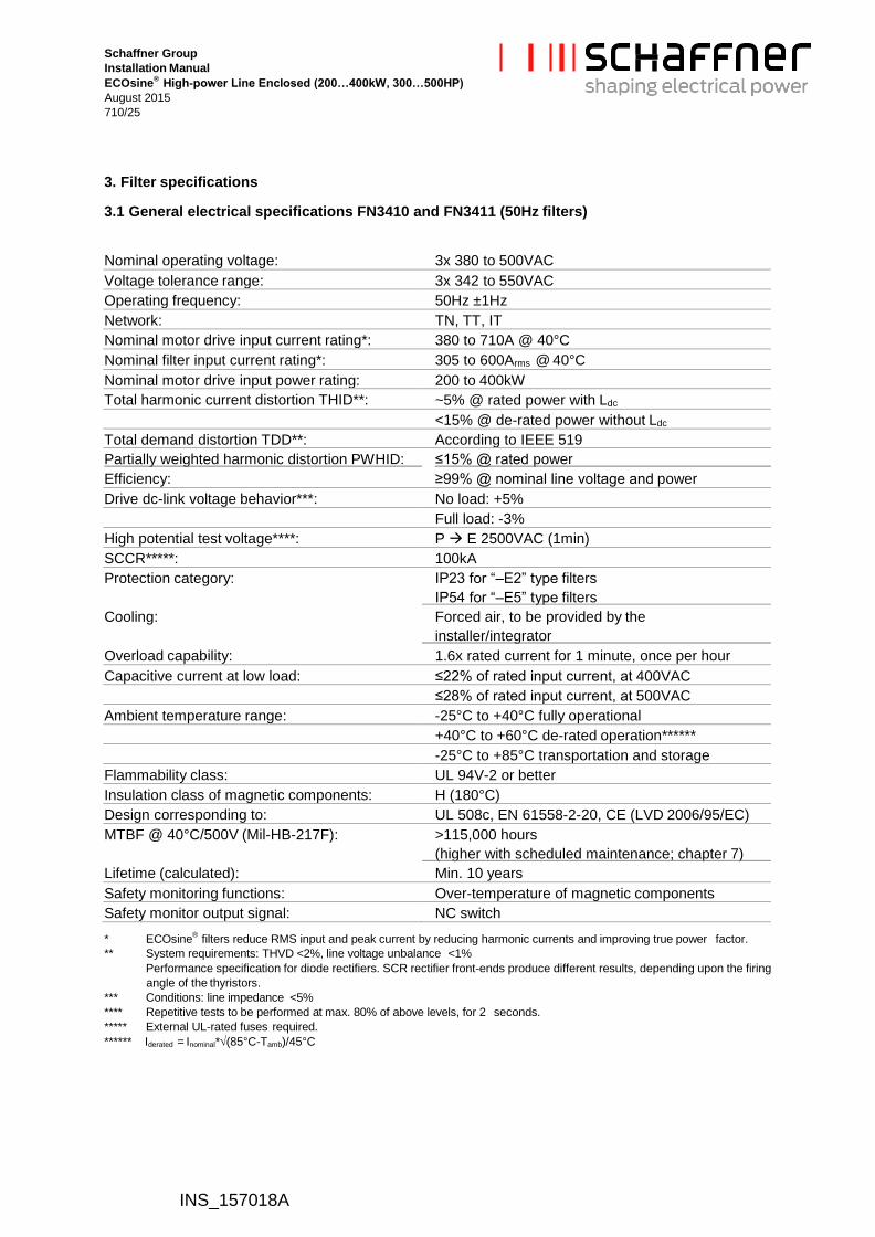
3.1 General electrical specifications FN3410 and FN3411 (50Hz filters)
Nominal operating voltage: 3x 380 to 500VAC
Voltage tolerance range: 3x 342 to 550VAC
Operating frequency: 50Hz ±1Hz
Network: TN, TT, IT
Nominal motor drive input current rating*: 380 to 710A @ 40°C
Nominal filter input current rating*: 305 to 600Arms @ 40°C
Nominal motor drive input power rating: 200 to 400kW
Total harmonic current distortion THID**: ~5% @ rated power with Ldc
<15% @ de-rated power without Ldc
Total demand distortion TDD**: According to IEEE 519
Partially weighted harmonic distortion PWHID: ≤15% @ rated power
Efficiency: ≥99% @ nominal line voltage and power
Drive dc-link voltage behavior***: No load: +5%
Full load: -3%
High potential test voltage****: P E 2500VAC (1min)
SCCR*****: 100kA
Protection category: IP23 for “–E2” type filters
IP54 for “–E5” type filters
Cooling: Forced air, to be provided by the
installer/integrator
Overload capability: 1.6x rated current for 1 minute, once per hour
Capacitive current at low load: ≤22% of rated input current, at 400VAC
≤28% of rated input current, at 500VAC
Ambient temperature range: -25°C to +40°C fully operational
+40°C to +60°C de-rated operation******
-25°C to +85°C transportation and storage
Flammability class: UL 94V-2 or better
Insulation class of magnetic components: H (180°C)
Design corresponding to: UL 508c, EN 61558-2-20, CE (LVD 2006/95/EC)
MTBF @ 40°C/500V (Mil-HB-217F): >115,000 hours
(higher with scheduled maintenance; chapter 7)
Lifetime (calculated): Min. 10 years
Safety monitoring functions: Over-temperature of magnetic components
Safety monitor output signal: NC switch
* ECOsine®
filters reduce RMS input and peak current by reducing harmonic currents and improving true power factor.
** System requirements: THVD <2%, line voltage unbalance <1%
Performance specification for diode rectifiers. SCR rectifier front-ends produce different results, depending upon the firing
angle of the thyristors.
*** Conditions: line impedance <5%
**** Repetitive tests to be performed at max. 80% of above levels, for 2 seconds.
***** External UL-rated fuses required.
****** Iderated = Inominal*(85°C-Tamb)/45°C
Schaffner Group
Installation Manual
ECOsine®
High-power Line Enclosed (200…400kW, 300…500HP)
August 2015
810/25
INS_157018A
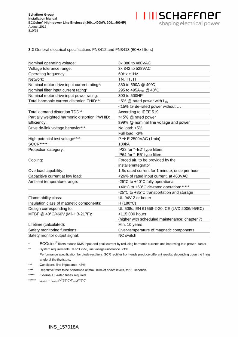
3.2 General electrical specifications FN3412 and FN3413 (60Hz filters)
Nominal operating voltage: 3x 380 to 480VAC
Voltage tolerance range: 3x 342 to 528VAC
Operating frequency: 60Hz ±1Hz
Network: TN, TT, IT
Nominal motor drive input current rating*: 380 to 590A @ 40°C
Nominal filter input current rating*: 295 to 495Arms @ 40°C
Nominal motor drive input power rating: 300 to 500HP
Total harmonic current distortion THID**: ~5% @ rated power with Ldc
<15% @ de-rated power without Ldc
Total demand distortion TDD**: According to IEEE 519
Partially weighted harmonic distortion PWHID: ≤15% @ rated power
Efficiency: ≥99% @ nominal line voltage and power
Drive dc-link voltage behavior***: No load: +5%
Full load: -3%
High potential test voltage****: P E 2500VAC (1min)
SCCR*****: 100kA
Protection category: IP23 for “–E2” type filters
IP54 for “–E5” type filters
Cooling: Forced air, to be provided by the
installer/integrator
Overload capability: 1.6x rated current for 1 minute, once per hour
Capacitive current at low load: <26% of rated input current, at 460VAC
Ambient temperature range: -25°C to +40°C fully operational
+40°C to +60°C de-rated operation******
-25°C to +85°C transportation and storage
Flammability class: UL 94V-2 or better
Insulation class of magnetic components: H (180°C)
Design corresponding to: UL 508c, EN 61558-2-20, CE (LVD 2006/95/EC)
MTBF @ 40°C/460V (Mil-HB-217F): >115,000 hours
(higher with scheduled maintenance; chapter 7)
Lifetime (calculated): Min. 10 years
Safety monitoring functions: Over-temperature of magnetic components
Safety monitor output signal: NC switch
* ECOsine®
filters reduce RMS input and peak current by reducing harmonic currents and improving true power factor.
** System requirements: THVD <2%, line voltage unbalance <1%
Performance specification for diode rectifiers. SCR rectifier front-ends produce different results, depending upon the firing
angle of the thyristors.
*** Conditions: line impedance <5%
**** Repetitive tests to be performed at max. 80% of above levels, for 2 seconds.
***** External UL-rated fuses required.
****** Iderated = Inominal*(85°C-Tamb)/45°C

Schaffner Group
Installation Manual
ECOsine®
High-power Line Enclosed (200…400kW, 300…500HP)
August 2015
910/25
INS_157018A
3.3 Additional specifications
For additional product specifications, selection tables and performance characteristics, please consult
the published datasheet on the Schaffner website www.schaffner.com or ask your local authorized
Schaffner partner.
Schaffner Group
Installation Manual
ECOsine®
High-power Line Enclosed (200…400kW, 300…500HP)
August 2015
1010/25
INS_157018A
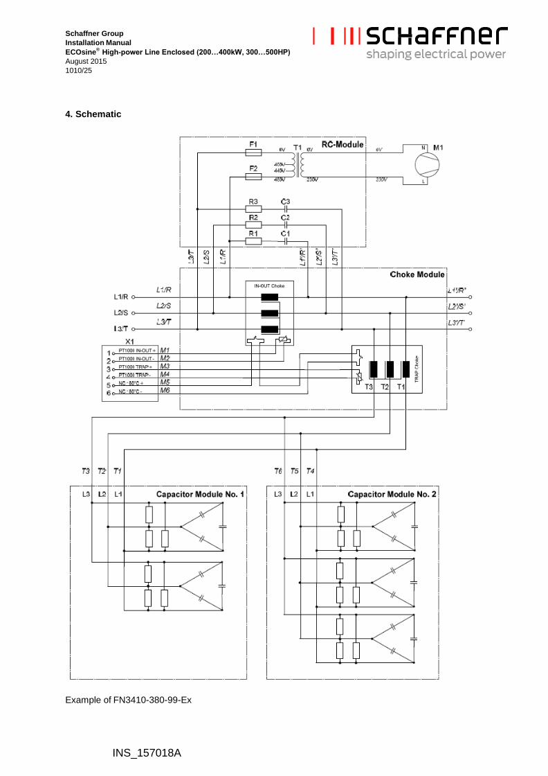
4. Schematic
Example of FN3410-380-99-Ex

Schaffner Group
Installation Manual
ECOsine®
High-power Line Enclosed (200…400kW, 300…500HP)
August 2015
1110/25
INS_157018A
5. Filter installation
Please follow the steps below to ensure a safe and satisfying filter function for many years.
5.1 Visual inspection
All Schaffner ECOsine®
filters have undergone rigorous testing before they left our ISO9001:2008
certified factory. They are packaged with great care in a sturdy container for international shipment.
However, carefully inspect the shipping container for damage that may have occurred in transit. Then
unpack the filter and carefully inspect for any signs of damage. Save the shipping container for future
transportation of the filter.
In the case of damage, please file a claim with the freight carrier involved immediately and contact
your local Schaffner partner for support. Under no circumstances install and energize a filter with
visible transportation damage.
If the filter is not going to be put in service upon receipt, store within the original container in a clean,
dry location, free of dust and chemicals.

Schaffner Group
Installation Manual
ECOsine®
High-power Line Enclosed (200…400kW, 300…500HP)
August 2015
1210/25
INS_157018A
Main filter components:
Capacitor Modules (1 to 3pcs)
Openings for line and load wiring
Air deflection sheet (top)
Fan and Filter air out
Inductor-Module
RC Module
Terminal of safety
temperature switch and
additional temp sensors
InOut-Choke
Air deflection
Filter air in
PE distribution
Trap-Choke
Schaffner Group
Installation Manual
ECOsine®
High-power Line Enclosed (200…400kW, 300…500HP)
August 2015
1310/25
INS_157018A
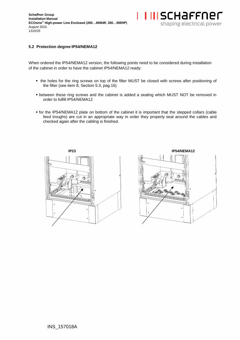
5.2 Protection degree IP54/NEMA12
When ordered the IP54/NEMA12 version, the following points need to be considered during installation
of the cabinet in order to have the cabinet IP54/NEMA12 ready:
the holes for the ring screws on top of the filter MUST be closed with screws after positioning of the filter (see item 8, Section 5.3, pag.16)
between these ring screws and the cabinet is added a sealing which MUST NOT be removed in order to fulfill IP54/NEMA12
for the IP54/NEMA12 plate on bottom of the cabinet it is important that the stepped collars (cable feed troughs) are cut in an appropriate way in order they properly seal around the cables and checked again after the cabling is finished.
IP23 IP54/NEMA12
Schaffner Group
Installation Manual
ECOsine®
High-power Line Enclosed (200…400kW, 300…500HP)
August 2015
1410/25
INS_157018A
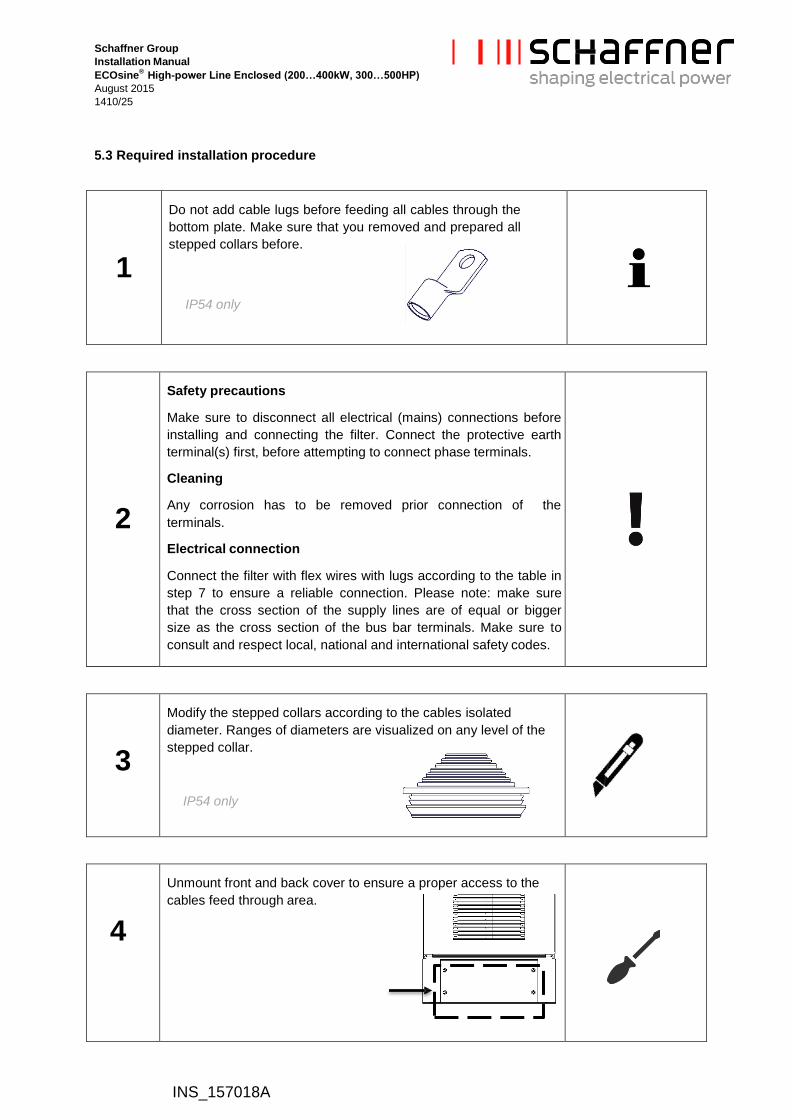
5.3 Required installation procedure
1
Do not add cable lugs before feeding all cables through the
bottom plate. Make sure that you removed and prepared all
stepped collars before.
IP54 only
2
Safety precautions
Make sure to disconnect all electrical (mains) connections before
installing and connecting the filter. Connect the protective earth
terminal(s) first, before attempting to connect phase terminals.
Cleaning
Any corrosion has to be removed prior connection of the
terminals.
Electrical connection
Connect the filter with flex wires with lugs according to the table in
step 7 to ensure a reliable connection. Please note: make sure
that the cross section of the supply lines are of equal or bigger
size as the cross section of the bus bar terminals. Make sure to
consult and respect local, national and international safety codes.
3
Modify the stepped collars according to the cables isolated
diameter. Ranges of diameters are visualized on any level of the
stepped collar.
IP54 only
4
Unmount front and back cover to ensure a proper access to the
cables feed through area.
Schaffner Group
Installation Manual
ECOsine®
High-power Line Enclosed (200…400kW, 300…500HP)
August 2015
1510/25
INS_157018A
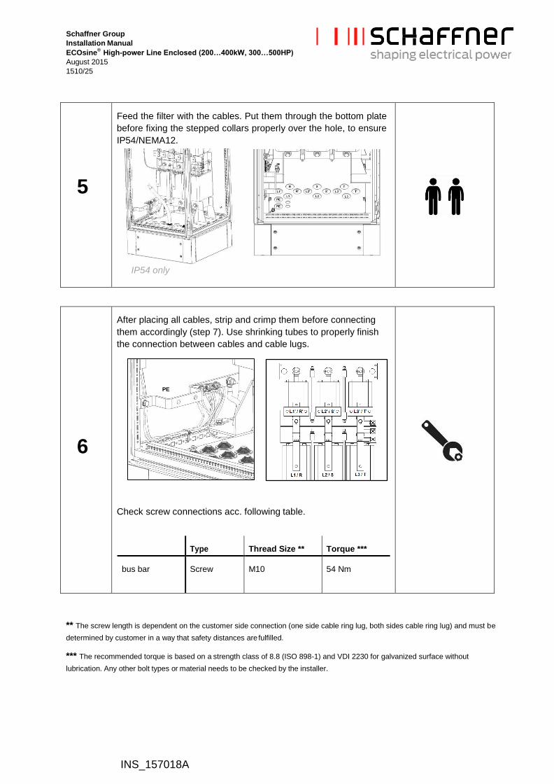
5
Feed the filter with the cables. Put them through the bottom plate
before fixing the stepped collars properly over the hole, to ensure
IP54/NEMA12.
IP54 only
6
After placing all cables, strip and crimp them before connecting
them accordingly (step 7). Use shrinking tubes to properly finish
the connection between cables and cable lugs.
PE
Check screw connections acc. following table.
Type Thread Size ** Torque ***
bus bar Screw M10 54 Nm
** The screw length is dependent on the customer side connection (one side cable ring lug, both sides cable ring lug) and must be
determined by customer in a way that safety distances are fulfilled.
*** The recommended torque is based on a strength class of 8.8 (ISO 898-1) and VDI 2230 for galvanized surface without
lubrication. Any other bolt types or material needs to be checked by the installer.

Schaffner Group
Installation Manual
ECOsine®
High-power Line Enclosed (200…400kW, 300…500HP)
August 2015
1610/25
INS_157018A
7
Fan Supply
A single phase transformer is used to provide the 230V supply of
the fan.
The transformer has 3 taps on the
primary side:
400V, 440 V and 480V.
At the primary side of the fan supply transformer, the
terminals corresponding to the application voltage must be
used!
The primary side is connected per default to 480VAC for
safety reasons.
Schaffner Group
Installation Manual
ECOsine®
High-power Line Enclosed (200…400kW, 300…500HP)
August 2015
1710/25
INS_157018A
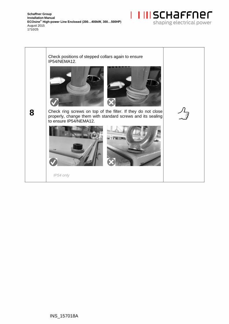
8
Check positions of stepped collars again to ensure IP54/NEMA12.
Check ring screws on top of the filter. If they do not close properly, change them with standard screws and its sealing to ensure IP54/NEMA12.
IP54 only

Schaffner Group
Installation Manual
ECOsine®
High-power Line Enclosed (200…400kW, 300…500HP)
August 2015
1810/25
INS_157018A
9
Installation of ventilation deflector
In order to ease the installation of the connecting cables, the
ventilation deflector has to be removed and shall be installed as
hereby illustrated, after cables are connected to the choke terminals.
Schaffner Group
Installation Manual
ECOsine®
High-power Line Enclosed (200…400kW, 300…500HP)
August 2015
1919/25
INS_157018A
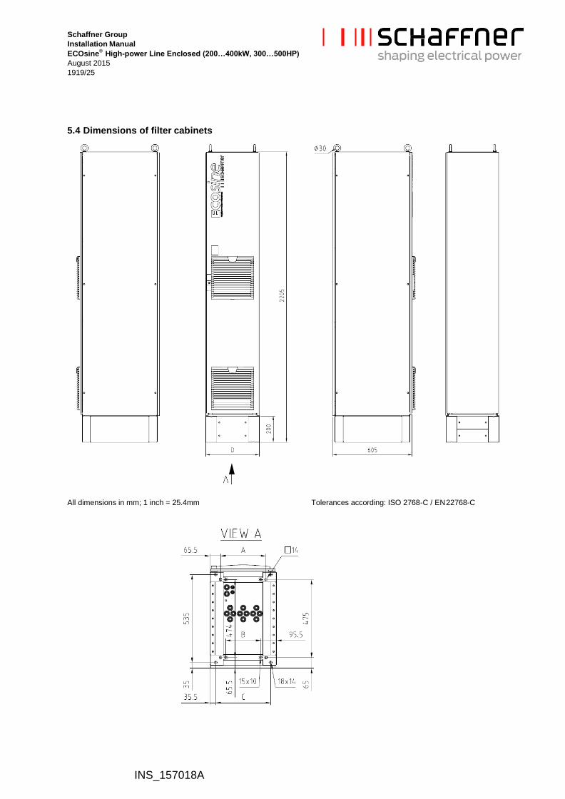
5.4 Dimensions of filter cabinets
All dimensions in mm; 1 inch = 25.4mm Tolerances according: ISO 2768-C / EN 22768-C
Schaffner Group
Installation Manual
ECOsine®
High-power Line Enclosed (200…400kW, 300…500HP)
August 2015
2019/25
INS_157018A
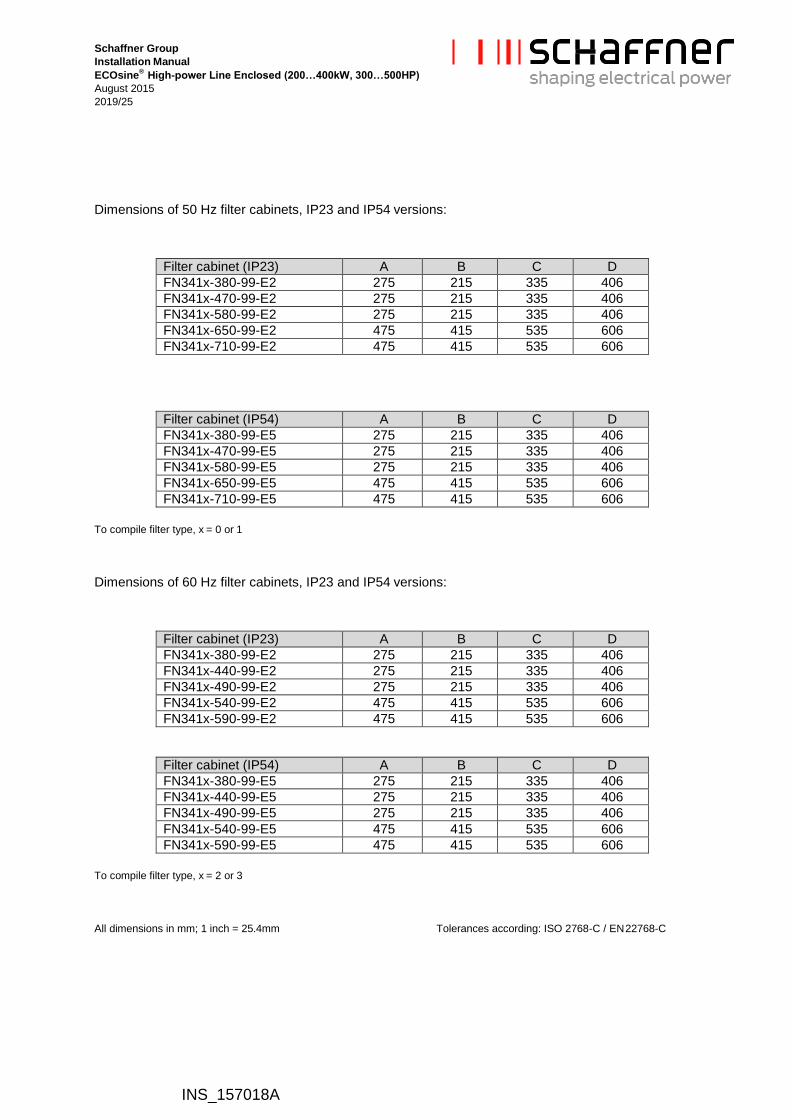
Dimensions of 50 Hz filter cabinets, IP23 and IP54 versions:
Filter cabinet (IP23) A B C D
FN341x-380-99-E2 275 215 335 406
FN341x-470-99-E2 275 215 335 406
FN341x-580-99-E2 275 215 335 406
FN341x-650-99-E2 475 415 535 606
FN341x-710-99-E2 475 415 535 606
Filter cabinet (IP54) A B C D
FN341x-380-99-E5 275 215 335 406
FN341x-470-99-E5 275 215 335 406
FN341x-580-99-E5 275 215 335 406
FN341x-650-99-E5 475 415 535 606
FN341x-710-99-E5 475 415 535 606
To compile filter type, x = 0 or 1
Dimensions of 60 Hz filter cabinets, IP23 and IP54 versions:
Filter cabinet (IP23) A B C D
FN341x-380-99-E2 275 215 335 406
FN341x-440-99-E2 275 215 335 406
FN341x-490-99-E2 275 215 335 406
FN341x-540-99-E2 475 415 535 606
FN341x-590-99-E2 475 415 535 606
Filter cabinet (IP54) A B C D
FN341x-380-99-E5 275 215 335 406
FN341x-440-99-E5 275 215 335 406
FN341x-490-99-E5 275 215 335 406
FN341x-540-99-E5 475 415 535 606
FN341x-590-99-E5 475 415 535 606
To compile filter type, x = 2 or 3
All dimensions in mm; 1 inch = 25.4mm Tolerances according: ISO 2768-C / EN 22768-C
Schaffner Group
Installation Manual
ECOsine®
High-power Line Enclosed (200…400kW, 300…500HP)
August 2015
2121/25
5.5 Further installation instructions
INS_157018A
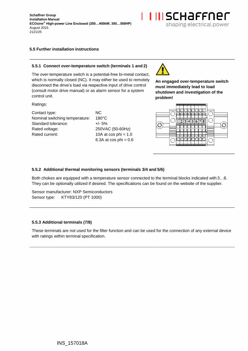
5.5.1 Connect over-temperature switch (terminals 1 and 2)
The over-temperature switch is a potential-free bi-metal contact,
which is normally closed (NC). It may either be used to remotely
disconnect the drive’s load via respective input of drive control
(consult motor drive manual) or as alarm sensor for a system
control unit.
Ratings:
Contact type: NC
Nominal switching temperature: 180°C
Standard tolerance: +/- 5%
Rated voltage: 250VAC (50-60Hz)
Rated current: 10A at cos phi = 1.0
6.3A at cos phi = 0.6
An engaged over-temperature switch
must immediately lead to load
shutdown and investigation of the
problem!
5.5.2 Additional thermal monitoring sensors (terminals 3/4 and 5/6)
Both chokes are equipped with a temperature sensor connected to the terminal blocks indicated with 3…6.
They can be optionally utilized if desired. The specifications can be found on the website of the supplier.
Sensor manufacturer: NXP Semiconductors
Sensor type: KTY83/120 (PT 1000)
5.5.3 Additional terminals (7/8)
These terminals are not used for the filter function and can be used for the connection of any external device
with ratings within terminal specification.
Schaffner Group
Installation Manual
ECOsine®
High-power Line Enclosed (200…400kW, 300…500HP)
August 2015
2222/25
INS_157018A
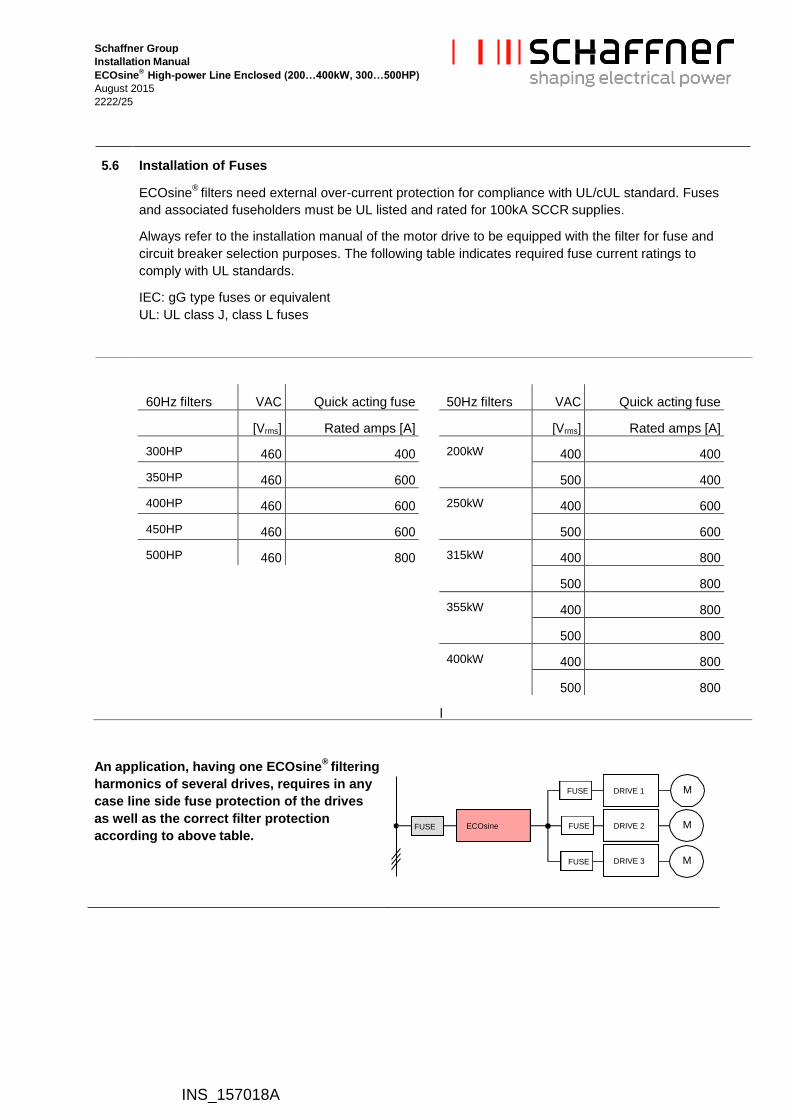
5.6 Installation of Fuses
ECOsine®
filters need external over-current protection for compliance with UL/cUL standard. Fuses
and associated fuseholders must be UL listed and rated for 100kA SCCR supplies.
Always refer to the installation manual of the motor drive to be equipped with the filter for fuse and
circuit breaker selection purposes. The following table indicates required fuse current ratings to
comply with UL standards.
IEC: gG type fuses or equivalent
UL: UL class J, class L fuses
l
An application, having one ECOsine®
filtering
harmonics of several drives, requires in any
case line side fuse protection of the drives
as well as the correct filter protection
according to above table.
60Hz filters VAC Quick acting fuse
[Vrms] Rated amps [A]
300HP 460 400
350HP 460 600
400HP 460 600
450HP 460 600
500HP 460 800
50Hz filters VAC Quick acting fuse
[Vrms] Rated amps [A]
200kW 400 400
500 400
250kW 400 600
500 600
315kW 400 800
500 800
355kW 400 800
500 800
400kW 400 800
500 800
FUSE DRIVE 1 M
FUSE ECOsine FUSE DRIVE 2 M
FUSE DRIVE 3 M

Schaffner Group
Installation Manual
ECOsine®
High-power Line Enclosed (200…400kW, 300…500HP)
August 2015
2322/25
INS_157018A
6. Filter maintenance
The passive harmonic filters described in this manual are equipped with long life components that
ensure a satisfactory function for many years under normal operating conditions. Any operation under
extreme conditions such as over-temperatures, overvoltage situations, polluted environments etc.
reduces the life expectancy. Following maintenance recommendation will help maximizing their life.
6.1 Maintenance schedule
Year 1 2 3 4 5 6 7 8 9 10 11 12
Check and clean fan & air filter X X X X X X X X X X X X
Replace fan & air filter X X
Check & tighten el. connections X X X X X X X X X X X X
Check values of power capacitors X X X X X X
Replace power capacitors X
6.2 Fan and air filter
Forced cooling devices are needed for the operation of Schaffner ECOsine®
filters up to their nominal
rating. Such cooling devices must be checked and cleaned regularly along with their air filters (if
installed) to ensure sufficient air flow at all times.
Note: increased audible noise is a typical indicator of a fan that needs maintenance or replacement also
outside of a maintenance schedule.
Note: a clogged air filter can greatly inhibit air circulation even with a brand new and powerful fan.
Before cleaning or replacing the cooling devices, make sure to consult the recommended maintenance
procedures and schedules of the supplier of the cooling device in use.
High voltage potentials are involved in the operation of this product. Always remove line side
power before attempting to perform maintenance, and let ample time elapse for the
capacitors to discharge to safe levels (<42V). Residual voltages are to be measured both line
to line and line to earth.

Schaffner Group
Installation Manual
ECOsine®
High-power Line Enclosed (200…400kW, 300…500HP)
August 2015
2422/25
INS_157018A
6.3 Power capacitors
The power capacitors supplied with the filter modules are high quality components with an expected life
time of up to 100’000 hours (11 years). Nevertheless, their useful service life can be shortened by
electrical or thermal stress beyond their specification.
Power capacitor damage may also be caused by severe abnormal supply voltage peaks (i.e. lightning –
depending upon system protection), but may only be recognizable through the measurement of line side
harmonics distortion. This may be checked with a modern energy meter or by regular checkup with a
power quality analyzer. According to the above considerations, a 2 year inspection interval is advisable.
Note: an inspection should as well be performed after extreme overvoltage situations in the system.
6.4 Electrical connections
Depending upon the environment and application, electrical connections, in particular threaded bolts
and nuts, can degrade over time by means of losing their initial tightening torque. This holds true not
only for the filter, but for any such joint within an electrical installation.
Therefore, Schaffner recommends to check and tighten all electrical connections on the occasion of a
regular scheduled maintenance of the entire device that incorporates the filter.
Note: make sure to check all electrical connections, also e.g. the factory wired terminals of the three
phase capacitors (tightening torque: 1.2Nm) and the PE terminals.

Schaffner Group
Installation Manual
ECOsine®
High-power Line Enclosed (200…400kW, 300…500HP)
August 2015
2522/25
INS_157018A
Disclaimer
This document has been carefully checked. However, Schaffner does not assume any liability for errors
or inaccuracies. Published specifications are subject to change without notice. Product suitability for an
area of application must ultimately be determined by the customer. In all cases, products must never be
operated outside their published specifications. Schaffner does not guarantee the availability of all
published products. Latest publications and a complete disclaimer can be downloaded from the
Schaffner website. All trademarks recognized.

![[Christina Schaffner] Translation Research and Int(BookFi.org)](https://static.fdocuments.us/doc/165x107/55cf9790550346d0339253fb/christina-schaffner-translation-research-and-intbookfiorg.jpg)