installation manual - ProSites
68
installation manual 10006030_11 EN
Transcript of installation manual - ProSites

installation manual
10006030_11
EN


TABLE OF CONTENTS
TOC - 1Installation manual
1 INTRODUCTION .................................................................................................................................... 1
2 PRE-INSTALLATION REQUIREMENTS .....................................................................................................22.1 Environmental requirements ........................................................................................................ 2
Wall construction ......................................................................................................................... 2Temperature & humidity .............................................................................................................. 2
2.2 Electrical requirements ................................................................................................................ 2Mains voltage ............................................................................................................................... 2Mains frequency .......................................................................................................................... 2Internal mains fuse ratings ........................................................................................................... 3External mains fuse recommendation ......................................................................................... 3Grounding .................................................................................................................................... 3Power consumption ..................................................................................................................... 3
3 INSTALLATION POSSIBILITIES ................................................................................................................43.1 Mounting alternatives ................................................................................................................... 4
Standard wall mounting in treatment room (see section 4 “STANDARD INSTALLATION TO A WALL” on page 11) ............................................................................................................ 4Wall mounting with remote control in treatment room (see section 7 “REMOTE CONTROL PANEL INSTALLATION” on page 48) ...................................................................... 5Ceiling mounting in treatment room (see section 5.1 “Ceiling installation” on page 25) .............. 6Dental unit mounting in treatment room (only Planmeca Compact dental unit) (see Planmeca Compact installation manual) ............................................................................. 7X-ray room with generator box/control panel outside the room (see sections 7 “REMOTE CONTROL PANEL INSTALLATION” on page 48 and 5.3 “Single stud installation” on page 38) .................................................................................... 8
3.2 Control panel assembling alternatives ......................................................................................... 9Standard assembly (see section 4 “STANDARD INSTALLATION TO A WALL” on page 11) ...................................................................................................................................... 9Remote assembly (see section 7 “REMOTE CONTROL PANEL INSTALLATION” on page 48) ...................................................................................................................................... 9Remote assembly with generator box (see section 6 “ATTACHING THE GENERATOR BOX WITHOUT THE ADAPTER PLATE” on page 44) ............................................................... 9Single stud assembly plate with control panel (see section 5.3 “Single stud installation” on page 38) ............................................................................................................................... 10Fixed control panel (contains a possibility to make “double exposure button” assembly) (see section 8 “FIXED CONTROL PANEL INSTALLATION” on page 51) ................................ 10
4 STANDARD INSTALLATION TO A WALL .............................................................................................. 114.1 Attaching the standard adapter plate to wall .............................................................................. 11
Attaching alternative 1 (recommended for concrete or brick wall) ............................................. 12Attaching alternative 2 (for wooden wall, not recommended for concrete wall) ......................... 14
4.2 Assembling the arm ................................................................................................................... 154.3 Changing the bracket arm movement area ............................................................................... 164.4 Mounting the arm ....................................................................................................................... 184.5 Installing the generator assembly .............................................................................................. 184.6 Connecting the cables ............................................................................................................... 20
Arm cable ................................................................................................................................... 20Mains cable (concealed wiring) ................................................................................................. 20
4.7 Attaching the control panel holder to the generator housing ..................................................... 224.8 Mounting the generator housing ................................................................................................ 234.9 Connecting the control panel cable ........................................................................................... 24
5 OTHER INSTALLATION ALTERNATIVES ................................................................................................ 255.1 Ceiling installation ...................................................................................................................... 25
Concrete ceiling ......................................................................................................................... 25

TABLE OF CONTENTS
Installation manualTOC - 2
Wooden ceiling .......................................................................................................................... 26Delight operating light installation .............................................................................................. 35
5.2 Adjustable ceiling adapter .......................................................................................................... 375.3 Single stud installation ............................................................................................................... 385.4 Installation to the Planmeca Compact dental unit ...................................................................... 43
6 ATTACHING THE GENERATOR BOX WITHOUT THE ADAPTER PLATE .................................................. 44
7 REMOTE CONTROL PANEL INSTALLATION .........................................................................................48
8 FIXED CONTROL PANEL INSTALLATION .............................................................................................518.1 Attaching the bottom plate ......................................................................................................... 518.2 Attaching the bottom plate to the wall socket ............................................................................ 528.3 Connecting the cables ............................................................................................................... 538.4 Attaching the fixed control panel to the bottom plate ................................................................. 55
9 EXTERNAL EXPOSURE BUTTON ...........................................................................................................56Disabling the exposure key on the control panel ....................................................................... 56
10 ATTACHING THE LONG CONE AND RECTANGULAR COLLIMATOR (OPTIONAL) ...........................57
11 FINAL ADJUSTMENTS ..........................................................................................................................5811.1 Adjusting the balance of the arm ............................................................................................... 5811.2 Adjusting the bracket arm angles .............................................................................................. 5911.3 Adjusting the stiffness of the tube head’s horizontal axle .......................................................... 60
12 RUNNING IN THE X-RAY UNIT ............................................................................................................61

INTRODUCTION
1 INTRODUCTION
This manual contains all the information required to install and set up the Planmeca Intra X-ray unit.Please read this manual carefully before installing the X-ray unit.
WARNING
Failure to install the Planmeca Intra X-ray unit in an approved location maybe dangerous to both patient and operator.
CAUTION
It is very important that the room in which the Planmeca Intra X-ray unit isinstalled and the position from which the equipment is operated arecorrectly shielded against radiation.
Since radiation safety requirements vary from country to country and stateto state, it is the responsibility of the installer to ensure that all local andnational safety regulations are met.
NOTE In case the Planmeca Dixi digital intra X-ray system is going to be installedto the Planmeca Intra X-ray unit, use the Dixi digital intra X-ray systeminstallation manual in conjunction with this manual.
The manufacturer, assembler and importer are responsible for the safe-ty, reliability and performance of the X-ray only if:
- installation, calibration, modification and repairs are carried out by qual-ified and authorized personnel
- electrical installations are carried out according to the appropriate re-quirements such as IEC364
- equipment is used according to the operating instructions
Planmeca pursues a policy of continual product development. Although everyeffort is made to produce up-to-date product documentation this publicationshould not be regarded as an infallible guide to current specifications. We re-serve the right to make changes without prior notice.
COPYRIGHT PLANMECA 2008-03PUBLICATION PART NUMBER 10006030 revision 11
Planmeca Intra X-ray unit 1Installation manual

PRE-INSTALLATION REQUIREMENTS
2 PRE-INSTALLATION REQUIREMENTS
2.1 Environmental requirements
Wall constructionThe wall construction must be able to resist a shear load of 75 kg (170 pounds) and withdrawal forceof 200 kg (445 pounds) at each of the four attachment locations. Otherwise, some additional mount-ing supports must be used to fulfill this requirement.
Temperature & humidityThe operating temperature range is from +15°C to +35°C, non condensing. The acceptable humidityrange is from 25% to 75%. The storage temperature range is from -5°C to +60°C.
NOTE If the X-ray unit has been stored at temperatures below +10°C for morethan a few hours, time must be allowed for the X-ray unit to reach the roomtemperature before connecting it to the mains voltage.
2.2 Electrical requirements
Mains voltageThe Planmeca Intra X-ray unit has been preset at the factory to one of the 3 different mains voltagesettings. Please check that the rating indicated on the type shield and the mains voltage selector onthe generator PCB (connector P4) corresponds to the local mains voltage. The possible voltage set-tings are:
• 100V~ (90V~...110V~)
• 110-115V~ (99V~...126V~)
• 220-240V~ (198V~...264V~)
NOTE Please note that the ratings of the internal (as well as external) mainsfuses are depending on the mains voltage setting.
CAUTION
Never connect the X-ray unit to the mains without first checking thevoltage setting. Incorrect voltage setting can cause damage to the X-rayelectronics.
Mains frequencyThe mains frequency is 50 or 60 Hz, and is independent on the mains voltage setting.
2 Planmeca Intra X-ray unit Installation manual

PRE-INSTALLATION REQUIREMENTS
Internal mains fuse ratingsThe Planmeca Intra X-ray unit is equipped with dual mains fuses (live and neutral). However, insome areas it is not allowed to have a fuse in the neutral wire. The neutral fuse is optionallybypassed at the factory, in which case the X-ray unit is equipped with one mains fuse.
The ratings for the internal mains fuses are:
• units with 100V~ or 110-115V~ voltage setting: 15AT, 250V, slow blow(6.3x32mm)(special fuse, manufacturerBussmann, type MDA)
• units with 220-240V~ voltage setting: 8AT, 250V, slow blow(6.3x32mm)(special fuse, manufacturerBussmann, type MDA)
External mains fuse recommendationThe recommendation for the external mains fuses are:
• units with 100V~ or 115V~ voltage setting: 16A, time lag
• units with 220-240V~ voltage setting: 10A, time lag
No other equipment should be connected to the same fused mains line as the X-ray unit. In somecountries an additional external fault current guard is also required.
GroundingThe Planmeca Intra X-ray unit must always be connected to a grounded outlet to fulfill the safetydirectives stated.
Power consumptionThe idle power consumption is less than 30VA. Maximum power consumption is 1000VA andoccurs during the exposure (maximum exposure time is 3.2 seconds).
Planmeca Intra X-ray unit 3Installation manual
INSTALLATION POSSIBILITIES
3 INSTALLATION POSSIBILITIES
3.1 Mounting alternatives
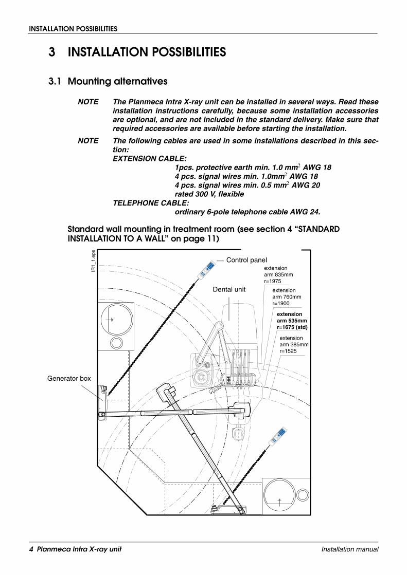
NOTE The Planmeca Intra X-ray unit can be installed in several ways. Read theseinstallation instructions carefully, because some installation accessoriesare optional, and are not included in the standard delivery. Make sure thatrequired accessories are available before starting the installation.
NOTE The following cables are used in some installations described in this sec-tion:EXTENSION CABLE:
1pcs. protective earth min. 1.0 mm2 AWG 184 pcs. signal wires min. 1.0mm2 AWG 184 pcs. signal wires min. 0.5 mm2 AWG 20rated 300 V, flexible
TELEPHONE CABLE:ordinary 6-pole telephone cable AWG 24.
Standard wall mounting in treatment room (see section 4 “STANDARD INSTALLATION TO A WALL” on page 11)
S
C
D
A
B
� � � �
READYPRET
mA
kV
s
BW
SELECT
MODE
READYPRET
mA
kV
s
BW
SELECT
MODE
IR1_
1.ep
s
extension arm 835mmr=1975
extension arm 535mmr=1675 (std)
extension arm 385mmr=1525
extension arm 760mmr=1900
Dental unit
Generator box
Control panel
4 Planmeca Intra X-ray unit Installation manual

INSTALLATION POSSIBILITIES
Wall mounting with remote control in treatment room (see section 7 “REMOTE CONTROL PANEL INSTALLATION” on page 48)
S
C
D
A
B
� � � �
RE
AD
Y
PR
ET
mA
kV
s
BW
SE
LE
CT
MO
DE
IR2_
1.ep
s
extension arm 835mmr=1975
extension arm 535mmr=1675 (std)
extension arm 385mmr=1525
extension arm 760mmr=1900
Dental unit
Generator box
Control panelTelephone cable, max. 12 m
Planmeca Intra X-ray unit 5Installation manual

INSTALLATION POSSIBILITIES
Ceiling mounting in treatment room (see section 5.1 “Ceiling installation” on page 25)
NOTE The extension arm 535mm (21.1 in.) is recommended for the ceiling instal-lation. Also the short extension arm can be used, but the long extensionarm is not recommended.
NOTE Both the Delight S and Delight operating light for unit mounting can beinstalled to the ceiling arm using an additional arm.
S
C
D
A
B
� � � �
READY
PRET
mA
kVs
BW
SELECT
MODE
IR3.
eps
Dental unit
Generator
Control panel
Extension cable,max. 12 m box
6 Planmeca Intra X-ray unit Installation manual

INSTALLATION POSSIBILITIES
Dental unit mounting in treatment room (only Planmeca Compact dental unit) (see Planmeca Compact installation manual)
NOTE Only short extension arm can be used in dental unit mounting.
S
C
D
A
B
� � � �
IR4.
eps
READY
PRET
mA
kVs
BW
SELECT
MODE
Dental unit
Generator
Control panel
Extension cable,max. 12 m
box
Planmeca Intra X-ray unit 7Installation manual

INSTALLATION POSSIBILITIES
X-ray room with generator box/control panel outside the room (see sections 7 “REMOTE CONTROL PANEL INSTALLATION” on page 48 and 5.3 “Single stud installation” on page 38)
READY
PRET
mAkV
s
BW
SELECTMODE
IR5_
1.ep
s
extension arm 835mmr=1975
extension arm 535mmr=1675 (std)
extension arm 385mmr=1525
extension arm 760mmr=1900 (std)
Generator box
Remote control panel
Telephone cable,max. 12 m
IR6_
1.ep
s
READYPRET
mA
kV
s
BW
SELECT
MODE
extension arm 835mmr=1975
extension arm 535mmr=1675 (std)
extension arm 385mmr=1525
extension arm 760mmr=1900
Generator box
Extension cable,max. 12 m
8 Planmeca Intra X-ray unit Installation manual

INSTALLATION POSSIBILITIES
3.2 Control panel assembling alternatives
Standard assembly (see section 4 “STANDARD INSTALLATION TO A WALL” on page 11)
Remote assembly (see section 7 “REMOTE CONTROL PANEL INSTALLATION” on page 48)
Remote assembly with generator box (see section 6 “ATTACHING THE GENERATOR BOX WITHOUT THE ADAPTER PLATE” on page 44)
I_fr
ont_
1.ep
s
READYPRET
mAkV
s
BW
SELECTMODE
Generator box
Control panel
I_fr
ont_
2.ep
s
READYPRET
mAkV
s
BW
SELECTMODE
Generator box
Control panel
Telephone cable
READY
PRET
mAkV
s
BW
SELECTMODE
I_fr
ont_
3.ep
s
Generator box
Control panel
Single stud plate
Ceiling mountingDental unit mounting
Extension cable
Planmeca Intra X-ray unit 9Installation manual

INSTALLATION POSSIBILITIES
Single stud assembly plate with control panel (see section 5.3 “Single stud installation” on page 38)
Fixed control panel (contains a possibility to make “double exposure button” assembly) (see section 8 “FIXED CONTROL PANEL INSTALLATION” on page 51)
I_fr
ont_
4.ep
s
READY
PRET
mAkV
s
BW
SELECTMODE
Generator boxControl panel
Extension cable
I_fr
ont_
5.ep
s
READY
PRET
mAkV
s
BW
SELECTMODE
Telephone cable
Generator boxFixed control
Double exposure button
panel
10 Planmeca Intra X-ray unit Installation manual

STANDARD INSTALLATION TO A WALL
4 STANDARD INSTALLATION TO A WALL
WARNING
Ensure that the power supply is switched off before installing thePlanmeca Intra X-ray unit.
4.1 Attaching the standard adapter plate to wall
The Planmeca Intra X-ray unit must be positioned in accordance with the information given in theinstallation pattern supplied with the unit. The X-ray unit should be positioned within the reach of thepower supply cable (3m) (118 in.). In the case that concealed wiring is used, the cable outlet shouldbe positioned next to (on the right-hand side) the adapter plate.
The wall plate is attached to the wall according to the instructions given in next pages. If the wall ismade of concrete or brick, use the M8x30 DIN 912 screws and the expansion anchors. If the wall ismade of wood or plaster, use the ø8x80 DIN 571 lag screws. Do not use the expansion anchors withwooden or plaster wall. See figure below.
IR7.
eps
Wall made ofconcrete or stone
Wooden or plaster wall
ø10 mm (0.4 in.)32…35 mm (1.25 in.)
ø5mm (0.2 in.)55…60 mm (2.2 in.)
Height 1120mm (44 in.)
Width min. 1100mm (min. 43 in.)
Width min. 1000mm (min. 39 in.)
The minimum widthsstated are measured usingthe 535 mm (21.1 in.) longextension arm.
For 385 mm (15.2 in.)extension arm subtract 150mm (5.9 in.) from the mini-mum width.
For 760 mm (30.0 in.)extension arm add 225 mm(8.9 in.) to the minimumwidth.
For 835 mm (32.9 in.)extension arm add 300 mm(12 in.) to the minimumwidth.
M8x30 DIN 912 ø8x80 DIN 571
Planmeca Intra X-ray unit 11Installation manual

STANDARD INSTALLATION TO A WALL
Attaching alternative 1 (recommended for concrete or brick wall) Mark the position of the left lower mounting hole to the wall on the height of 1120 mm (44 in.). Drillone ø10mm (0.4 in.), 32...35 mm (1.25 in.) in depth, hole and place the expansion anchor into it.Make sure that the end of the anchor is under the wall surface, but not more than 5 mm. Hit thewedge of the anchor firmly to the bottom of the hole. Remove the adjustment nuts from the threeother mounting holes. Attach the adapter plate to the wall with one of the fastening screws andadjust the plate exactly to horizontal position.
Insert the drilling tool to one of the holes and drill the second hole using the drilling tool as a guide.Unscrew the drilling tool and insert the second expansion anchor as described above, replace theadjustment nut and attach the screw.
1
1
12
34
5
6
Ins1
.eps
Adjustment nut
Adapter plate
Ins2
.eps
12
34
5
6
2
3
54
Drilling tool, part number 6525091
Spirit level
12 Planmeca Intra X-ray unit Installation manual

STANDARD INSTALLATION TO A WALL
Drill the two other holes.
Remove the adapter plate and place the expansion anchors into the last two holes.
Attach the plate to the wall with four M8x30 DIN 912 screws and ø8.4/17 DIN 125 washers. You canuse two adjustment plates under the adapter plate.
Use the adjustment nuts and the adjustment plates with the screws at each corner of the adapterplate. Adjust the wall adapter bearing to vertical position by opening slightly the mounting screwsand turning the adjustment nuts to required position. The wall adapter moves towards the wall whenturning the nut counterclockwise.
Finally, tighten all the mounting screws.
Ins3
.eps
Adjustment plate(optional)
Ins4
.eps
Adjust
Check
Planmeca Intra X-ray unit 13Installation manual

STANDARD INSTALLATION TO A WALL
Attaching alternative 2 (for wooden wall, not recommended for concrete wall)Use the installation pattern as a template and mark the positions where the holes for the four attach-ing screws will be drilled. Use a spirit level to ensure that the adapter plate will be level.
If the wall is made of concrete or brick, drill ø10mm (0.4 in.), 32…35 mm (1.25 in.) in depth, holesand place the expansion anchors into them. Attach the adapter plate to the wall with the four M8x30DIN 912 screws and the ø8.4 DIN 125 washers.
If the wall is made of wood or plaster, drill ø5 mm (0.2 in.), 55…60 mm (2.2 in.) in depth, holes forthe attachment screws. Do not use the expansion anchors with wooden or plaster wall. Attach theadapter plate to the wall with the four ø8x80 DIN 571 lag screws and the ø8.4 DIN 125 washers.You can use two adjustment plates under the adapter plate.
Use the adjustment nuts with the screws at each corner of the adapter plate. Adjust the wall adapterbearing to vertical position by opening slightly the mounting screws and turning the adjustment nutsto required position. The wall adapter moves towards the wall when turning the nut counterclock-wise.
Finally, tighten all the mounting screws.
Ins1
6.ep
s
Adjustment plate(optional)
Ins4
.eps
Adjust
Check
14 Planmeca Intra X-ray unit Installation manual

STANDARD INSTALLATION TO A WALL
4.2 Assembling the arm
CAUTION
Care must be taken when assembling the arm for not to damage the armcable.
NOTE Normally the bracket arm does not turn above the extension arm. In caseyou need to change the movement area of the bracket arm, refer to section4.3 “Changing the bracket arm movement area” on page 16.
Route the arm cable and the Dixi interconnection cable through the extension arm shaft housing.Assemble the bracket arm to the extension arm by pushing the bracket arm shaft into the housing.Secure the bracket arm with the locking plate. Route the cables through the extension arm and armshaft. Place the cover plug back to the end of the extension arm.
Uni
t_ar
m2_
00.e
ps
Extension arm
Arm cable
Arm shaft housing
Bracket arm
join
t1.e
ps
Locking plate
Dixi interconnection cable
Extensionarm shaft
Planmeca Intra X-ray unit 15Installation manual
STANDARD INSTALLATION TO A WALL
4.3 Changing the bracket arm movement area
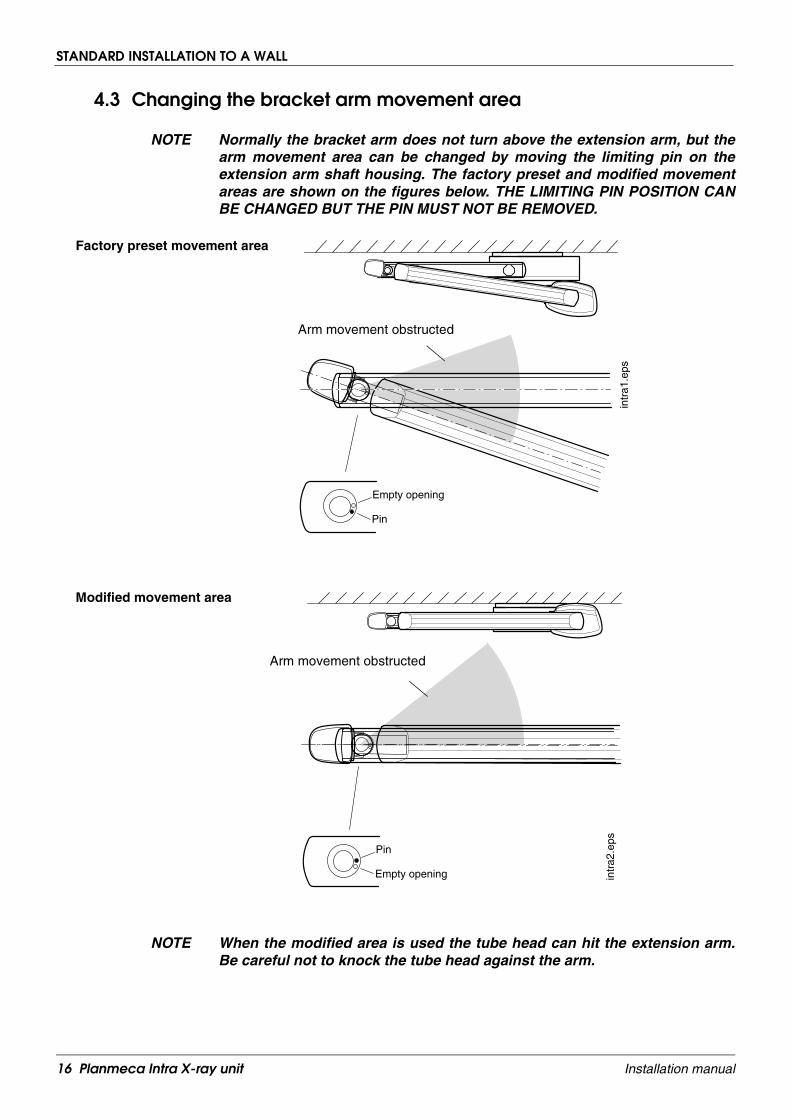
NOTE Normally the bracket arm does not turn above the extension arm, but thearm movement area can be changed by moving the limiting pin on theextension arm shaft housing. The factory preset and modified movementareas are shown on the figures below. THE LIMITING PIN POSITION CANBE CHANGED BUT THE PIN MUST NOT BE REMOVED.
NOTE When the modified area is used the tube head can hit the extension arm.Be careful not to knock the tube head against the arm.
Factory preset movement area
Empty opening
Pin
intr
a1.e
ps
Arm movement obstructed
Pin
Empty opening intr
a2.e
ps
Arm movement obstructed
Modified movement area
16 Planmeca Intra X-ray unit Installation manual

STANDARD INSTALLATION TO A WALL
Unscrew the two screws that hold the housing on the extension arm and remove the shaft.
Remove the limiting pin from the housing by using a thin screwdriver and hammer.
Attach the pin to the other opening on the housing so that the pin is level with the inner surface ofthe housing (see figure below).
join
t2.e
ps
Arm shaft housing
join
t3.e
ps
MODIFIED
PRESET
join
t4.e
ps
Limiting pin Housing surface
Openings for limiting pin
Planmeca Intra X-ray unit 17Installation manual
STANDARD INSTALLATION TO A WALL
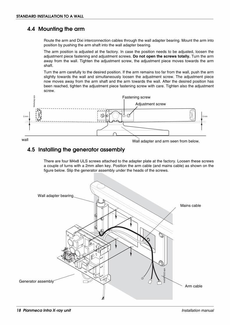
4.4 Mounting the arm
Route the arm and Dixi interconnection cables through the wall adapter bearing. Mount the arm intoposition by pushing the arm shaft into the wall adapter bearing.
The arm position is adjusted at the factory. In case the position needs to be adjusted, loosen theadjustment piece fastening and adjustment screws. Do not open the screws totally. Turn the armaway from the wall. Tighten the adjustment screw, the adjustment piece moves towards the armshaft.
Turn the arm carefully to the desired position. If the arm remains too far from the wall, push the armslightly towards the wall and simultaneously loosen the adjustment screw. The adjustment piecenow moves away from the arm shaft and the arm towards the wall. After the desired position hasbeen reached, tighten the adjustment piece fastening screw with care. Tighten also the adjustmentscrew.
4.5 Installing the generator assembly
There are four M4x8 ULS screws attached to the adapter plate at the factory. Loosen these screwsa couple of turns with a 2mm allen key. Position the arm cable (and mains cable) as shown on thefigure below. Slip the generator assembly under the heads of the screws.
Wal
lada
p.ep
s
3 mm3 mm
wall Wall adapter and arm seen from below.
Fastening screw
Adjustment screw
Ins5
AP
SU
2.ep
s
Mains cable
Wall adapter bearing
Generator assemblyArm cable
18 Planmeca Intra X-ray unit Installation manual

STANDARD INSTALLATION TO A WALL
Secure the generator assembly into position by tightening the four screws through the openings onthe generator PCB.
Ins6
AP
SU
2.ep
s
Planmeca Intra X-ray unit 19Installation manual

STANDARD INSTALLATION TO A WALL
4.6 Connecting the cables
WARNING
Ensure that the power supply is switched off before connecting the cables.
Arm cableConnect the grounding lead of the arm cable to the grounding point located on the right side of thegenerator assembly. Connect the control leads of the arm cable (6-pole connector) to the terminalP8 on the generator PCB. Connect the power leads (3-pole connector) of the arm cable to the termi-nal P1 on the generator PCB. Snap the ferrite to the arm cable as shown on the figure on next page.
Mains cable (concealed wiring)In the case that mains voltage is supplied via concealed wiring route the mains cable between theadapter plate and the generator assembly.
Connect the grounding lead to the grounding point next to the mains switch. Connect the neutralwire to the mains input terminal (P5) marked N. Connect the live wire to the mains input terminal(P5) marked L.
Generator PCB version -C or later (from X-ray unit’s serial number IXRF58018): When the con-cealed wiring is used the cable coming from the ON/OFF switch to the connector P7 must be movedto the connecto P10. Also the fuse F3 must be removed.
Remove Fuse F3
Neutral
Line
Blue
Brown
Blue
Brown
20 Planmeca Intra X-ray unit Installation manual

STANDARD INSTALLATION TO A WALL
NOTE In case the X-ray units own power supply cable and the strain reliefer areremoved from the generator assembly (mains voltage is supplied via con-cealed wiring), cover the opening with a plug supplied with the X-ray unit.
Connect the Dixi interconnection cable to the Panel mounted RJ45 adapter located beside the on/offswitch and secure the cable with the cable clamp. If needed, attach the cable to the wall adapterbearing with a cable tie.
NOTE The Dixi digital intra X-ray system is installed according to the instructionsgiven in the Dixi digital X-ray systems installation manual.
I_te
ch_3
AP
SU
2.ep
s
P5
P3
P6
P8
P9
P7
P1
Snap-on ferrite
Planmeca Intra X-ray unit 21Installation manual

STANDARD INSTALLATION TO A WALL
4.7 Attaching the control panel holder to the generator housing
Drill two ø3.5-4mm (0.14-0.16 in.) holes for the control panel holder to the generator housing. Thehole positions are marked to the inner side of the cover with collars.
Attach the control panel holder to the generator housing with the two PT 3x22 rst WN1451 screws.
12 3 4 5
6
ins1
4.ep
s
Generator housing
Ins1
5.ep
s
Control panel holder
Generator housing
22 Planmeca Intra X-ray unit Installation manual

STANDARD INSTALLATION TO A WALL
4.8 Mounting the generator housing
Place the generator housing over the generator assembly. Secure the cover into position with thethree M4x6 ULS screws.
Attach the generator housing cover plate to its position.
Complies with DHHS radiationperformancestandards 21 CFR Subchapter J. 220V - 240 V AT
AT8
100V - 115 V 1570kV maximum 1800 mAs/h
Total filtration: 2,0 mm EquAlWARNING:For continued protectionagainst risk of fire replace only with same type and rating of fuse.
Manufactured by: Planmeca OY 00880 HELSINKI FINLAND LBL-Z-006D
1000VA 50/60Hz
0537
I_7A
.eps
eps
Generator housing cover plate
Planmeca Intra X-ray unit 23Installation manual

STANDARD INSTALLATION TO A WALL
4.9 Connecting the control panel cable
Connect the control panel cable to its terminal at the underside of the generator box.
READYPRET
mAkV
s
BW
SELECTMODE
Complies with DHHS radiationperformancestandards 21 CFR Subchapter J. 220V - 240 V AT
AT8
100V - 115 V 1570kV maximum 1800 mAs/h
Total filtration: 2,0 mm EquAlWARNING:For continued protectionagainst risk of fire replace only with same type and rating of fuse.
Manufactured by: Planmeca OY 00880 HELSINKI FINLAND LBL-Z-006D
1000VA 50/60Hz
Control panel cable
24 Planmeca Intra X-ray unit Installation manual

OTHER INSTALLATION ALTERNATIVES
5 OTHER INSTALLATION ALTERNATIVES
WARNING
Ensure that the power supply is switched off before installing thePlanmeca Intra X-ray unit.
NOTE With the installation methods described in this section the generator boxis installed directly to a wall without using a wall adapter plate. Refer to thesection 6 “ATTACHING THE GENERATOR BOX WITHOUT THE ADAPTERPLATE” on page 44.
5.1 Ceiling installation
Concrete ceiling Mark the place of the adapter plate to the ceiling. Drill one ø10 mm (0.4 in.), 32...35 mm (1.25 in.) indepth, hole and place the expansion anchor into it. Attach the adapter plate to the ceiling with one ofthe fastening screws.
Remove the adjustment nuts from the three mounting holes. Attach the drilling tool to one of theholes and drill the second hole using the drilling tool as a guide. Drill the two other holes in the sameway. Remove the adapter plate and insert the expansion anchors into the holes.
Attach the plate to the ceiling with four M8x35 DIN 912 screws and ø8.4/17 DIN 125 washers. Usethe adjustment nuts and the adjustment plates with the screws at each corner of the adapter plate.
Adapter plate
Planmeca Intra X-ray unit 25Installation manual

OTHER INSTALLATION ALTERNATIVES
Wooden ceilingAttach the adapter plate to the ceiling with four ø8x80 DIN 571 lag screws. Do not use the expan-sion anchors with wooden ceiling. Use the adjustment nuts and the adjustment plates with thescrews at each corner of the adapter plate.
NOTE If the concealed wiring is not used, the extension cable must be lead sothat there is at least 1.2 m cable after adapter plate.
min. 1.2 m
26 Planmeca Intra X-ray unit Installation manual

OTHER INSTALLATION ALTERNATIVES
Shorten the ceiling arm if needed and attach the mounting rings to the arm. Do not tighten thescrews yet.
NOTE If the optional adapter cover is used, attach it to its position before attach-ing the ceiling arm.
Ceiling arm
Mounting rings
Note, that the attachment screws of the uppermounting ring must be on the lower edge of the ring, and the screws of the lower ring on the upper edge.
Adapter cover
Ceiling arm
Planmeca Intra X-ray unit 27Installation manual

OTHER INSTALLATION ALTERNATIVES
Install the ceiling arm to the adapter as follows.
If the operating light is installed to the ceiling arm, position the arm according to the figure below(opening away from the chair).
NOTE The ceiling arm is locked to the arm adapter by making a dent with amounting ring screw to the arm above the adapter collar. The dent mustnot be in line with the machining on the adapter collar.
S
C D
A
B
88
88
Opening
500 mm
1000 mm
ceil1
.eps
Arm adapterMachining
Ceiling arm
Mounting rings
Adapter collar
28 Planmeca Intra X-ray unit Installation manual
OTHER INSTALLATION ALTERNATIVES
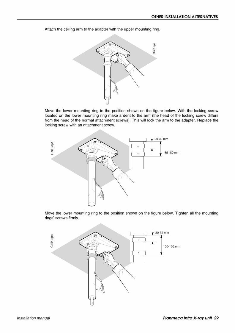
Attach the ceiling arm to the adapter with the upper mounting ring.
Move the lower mounting ring to the position shown on the figure below. With the locking screwlocated on the lower mounting ring make a dent to the arm (the head of the locking screw differsfrom the head of the normal attachment screws). This will lock the arm to the adapter. Replace thelocking screw with an attachment screw.
Move the lower mounting ring to the position shown on the figure below. Tighten all the mountingrings’ screws firmly.
Cei
l2.e
ps
30-32 mm
65 - 80 mmCei
l3.e
ps
30-32 mm
100-105 mmCei
l4.e
ps
Planmeca Intra X-ray unit 29Installation manual

OTHER INSTALLATION ALTERNATIVES
With a spirit level make sure that the ceiling arm is vertical. Adjust its position with the adjustmentnuts, if needed.
Attach the cover label over the dent.
Remove the extension arm shaft. Remove the shaft nut by hitting it as shown on the figure below.Remove the support plate and the shaft. The shaft is not needed in this installation.
Adjustment nutC
eil5
.eps
Arm shaft
30 Planmeca Intra X-ray unit Installation manual

OTHER INSTALLATION ALTERNATIVES
Assemble the bracket arm to the extension arm, refer to the section 4.2 “Assembling the arm” onpage 15. Assemble the bearing housing to the extension arm as described in figure below.
Install the X-ray unit to the ceiling arm and lock it immediately to its position with the fasteningscrew.
Cei
lada
p5.e
ps
Shaft nut
Support plate
Attach the shaft nut
Planmeca Intra X-ray unit 31Installation manual

OTHER INSTALLATION ALTERNATIVES
NOTE The ceiling arm shaft can be locked temporarily to ease the installation ofthe unit.
Intr
a ce
il.ad
ap.a
ssy
7 05
0397
Cei
lada
p6.e
ps
Fastening screw
Tighten this locking screw
Tighten firmly
32 Planmeca Intra X-ray unit Installation manual

OTHER INSTALLATION ALTERNATIVES
Route the arm and Dixi interconnection cables from the extension arm to the ceiling arm. In case theDixi digital intra X-ray system is not installed leave the Dixi interconnection cable into the ceiling armas shown on the figure below.
NOTE The Dixi digital intra X-ray system is installed according to the instructionsgiven in the Dixi digital X-ray systems installation manual.
Connect the cables according to the figure below. Note, that it does not matter which way the yellowleads (HV1 and HV2) are connected to the connectors HV1 and HV2.
Cei
lada
p8A
.eps
Arm cableDixi interconnection cable
P6
P7
P9
P8
HV1HV2
+12VEXP
KVCGND
AUX1AUX2
SCLELMP
N.C.
Grn
Extension cable max.12 m Extension cable Con-nectors
Molex-3
Molex-6
Generator PCB Arm cable (Std.)
HV1
HV2
+12V
EXP
+12V
KVCGNDSCL
GND
ELMP
ELMP
GryBrnPink
1
1
23
2
3
4
5
6
Molex-3
Molex-6
1
2
3
Screw terminal
P1
P8
P14
Yel
Yel / Grn
Wht
Gry
BlkRedBrnBluPink
Ferrite
Planmeca Intra X-ray unit 33Installation manual

OTHER INSTALLATION ALTERNATIVES
Fasten the cover to the opening of the ceiling arm.
Loosen the locking screw and either leave it loose, so that the arm can be rotated (700°), or tightenit to the position desired by the customer. Attach the cover plugs.
Cei
lada
p9A
.eps
34 Planmeca Intra X-ray unit Installation manual

OTHER INSTALLATION ALTERNATIVES
Delight operating light installationThe operating light can be installed to the ceiling arm of the Planmeca Intra X-ray unit.
Delight operating light without power contol
Make sure that the operating light cable is installed.
Attach the arm and the Delight operating light according to the figure below. Make sure that the lightcable is in the groove of the light arm pivot when attaching the light to the horizontal arm.
BLACK
YE
LLO
WB
LAC
K
BLA
CK
B L
UE
YE
LLO
W
BLU
E
YELLOW
BLUE BULB
SWITCH
BULB AND SWITCH COMMON
BLACK
NOTE !The ABSOLUTE MAXIMUM allowed bulb voltage is 18,5 Vrmsmeasured at the bulb socket.
Delight internal connection
Bulb MAX.150W 24V
Momentarypush-buttonswitch 50V 10mA
Brown Blue
Yellow YellowIntr
a_d
elig
ht_
ceili
ng
_in
st_0
7.ep
s
M6x17 DIN 7991
M4x6 DIN 912
M6x12 DIN 912
ø4 DIN 6798
ø3.5x13
M6x17 DIN 7991
DIN 7981
Bushing
Rotation limiter
Planmeca Intra X-ray unit 35Installation manual

OTHER INSTALLATION ALTERNATIVES
Delight operating light with power contol
Attach the arm and the Delight operating light according to the figure below.
Make sure that the light cable is in the groove of the light arm pivot when attaching the power controlassembly to the light.
Add some vaseline to the light arm pivot. Route the light cable through the openings on the powercontrol assembly and push the light arm pivot into the power control assembly opening.
Carefully push the light power supply cable into the groove of the light arm pivot. Push the pivotthrough the power control assembly openings so that the assembly hits the pin located on the lightarm. Push the power supply cable into the power control assembly and rotate the power controlassembly so that the pin in the light arm goes into the hole on the power control assembly.
Attach two spring bushings to the light arm pivot.
NOTE Do not tighten the ligth cable but leave it a bit loose.
Connect the Delight wires according to the instructions given in Delight Installation manual, publica-tion number 588200.
Intr
a_d
elig
ht_
AC
_cei
ling
_in
st_0
7.ep
s
M6x17
M6x12 DIN 912
ø4 DIN 6798
ø3.5x13
M6x17 DIN 7991
DIN 7981
Power control assembly
Rotation limiter
DIN 7991
Spring bushings
36 Planmeca Intra X-ray unit Installation manual

OTHER INSTALLATION ALTERNATIVES
5.2 Adjustable ceiling adapter
Concrete ceiling: Mark the place of the adapter plate to the ceiling. Drill six ø10 mm (0.4 in.),32...35 mm (1.25 in.) in depth, holes and place the expansion anchors into them. Insert the expan-sion anchors into the holes. Attach the upper part of the adapter to the concrete ceiling with sixM8x30 DIN 912 screws and ø8.4/17 DIN 125 washers.
Wooden ceiling: Attach the upper part of the adapter to the wooden ceiling with six ø8x80 DIN 571lag screws. Do not use the expansion anchors with wooden ceiling.
Adjust the height of the ceiling adapter so that the lower plate of the adapter is on a level with theceiling. Lock the lower part to the upper part with the eight M8x16 DIN 912 screws and M8 DIN 934nuts.
Attach the standard adapter plate to the adjustable ceiling adapter with four M8x30 DIN 912 screwsand ø8.4/17 DIN 125 washers. Use the adjustment nuts and the adjustment plates with the screwsat each corner of the adapter plate. Continue the installation according to the instructions given insection 5.1 “Ceiling installation” on page 25.
Intr
a ce
il.ad
j.ada
pter
020
597
Upper part of the adjustable adapter
Lower plate of the adjustable adapter
Adapter plate
Planmeca Intra X-ray unit 37Installation manual

OTHER INSTALLATION ALTERNATIVES
5.3 Single stud installation
NOTE Use the single stud assembling plate when you are installing the PlanmecaIntra to a cabinet, to an end of a wall, or to a single stud (plaster) wall.
Use the installation pattern or the single stud adapter plate as a template and mark the positionswhere the holes for the attaching screws will be drilled.
If the wall is made of concrete or brick, drill ø10mm (0.4 in.), 32…35 mm (1.25 in.) in depth, holesand place the expansion anchors into them. If the wall is made of wood, drill ø5 mm (0.2 in.), 55…60mm (2.2 in.) in depth, holes for the attachment screws. Do not use the expansion anchors withwooden wall.
Attach the adapter plate to the wall with at least three M8x80 DIN 571 screws and the ø8.4 DIN 125washers. Route the extension cable through the opening on the adapter plate.
Assemble the bracket arm to the extension arm, refer to the section 4.2 “Assembling the arm” onpage 15.
I_8A
.eps
Single stud adapter
Optional
38 Planmeca Intra X-ray unit Installation manual

OTHER INSTALLATION ALTERNATIVES
Route the arm and Dixi interconnection cables through the wall adapter bearing. Mount the arm intoposition by pushing the arm shaft into the wall adapter bearing.
Using a spirit level adjust the arm position with the four screws of the wall adapter bearing.
I_9A
.eps
I_10
A.e
ps
Adjust the arm position withthese screws.
Planmeca Intra X-ray unit 39Installation manual

OTHER INSTALLATION ALTERNATIVES
NOTE The extension arm is not horizontal, but its end is 2 mm over the horizontallevel. When the assembly is completed, the weight of the unit bends thearm to horizontal position.
Connect the grounding leads to the grounding point in the bottom of the adapter plate.
I_13
A.e
ps
2 mm2 mmI_
11A
.eps
cover partearthing cable
40 Planmeca Intra X-ray unit Installation manual

OTHER INSTALLATION ALTERNATIVES
Connect the arm cable and extension cable according to the figure below. Note, that it does not mat-ter which way the yellow leads (HV1 and HV2) are connected to the connectors HV1 and HV2.
Connect the Dixi interconnection cable to the Panel mounted RJ45 modular adapter located on thebase plate of the single stud assembly and secure the cable to the single stud wall plate with thecable clamp as shown on the figure below.
NOTE The Dixi digital intra X-ray system is installed according to the instructionsgiven in the Dixi digital X-ray systems installation manual.
P6
P7
P9
P8
HV1HV2
+12VEXP
KVCGND
AUX1AUX2
SCLELMP
N.C.
Grn
Extension cable max.12 m Extension cable Con-nectors
Molex-3
Molex-6
Generator PCB Arm cable (Std.)
HV1
HV2
+12V
EXP
+12V
KVCGNDSCL
GND
ELMP
ELMP
GryBrnPink
1
1
23
2
3
4
5
6
Molex-3
Molex-6
1
2
3
Screw terminal
P1
P8
P14
Yel
Yel / Grn
Wht
Gry
BlkRedBrnBluPink
Ferrite
Optional Ready light
sing
lest
ud_A
.eps
Dixi interconnection cable
Planmeca Intra X-ray unit 41Installation manual

OTHER INSTALLATION ALTERNATIVES
If the control panel is attached to the single stud cover, attach the control panel holder before attach-ing the cover to its position. Drill two attachment holes to the cover as shown on the figure belowand attach the holder to the cover with the two PT 3x22 rst WN1451 screws.
19mm
65mm
19mm
Ø 3,5mm
Screw 3x22 PTCode 00326195
I_14
.eps
42 Planmeca Intra X-ray unit Installation manual

OTHER INSTALLATION ALTERNATIVES
Connect the exposure warning indicator light cable to the connector P4 on the Extension cable PCBand attach the cover part earthing cable to the connector on the cover. Attach the cover to positionwith one attachment screw and slide and the upper cover plate to its position.
5.4 Installation to the Planmeca Compact dental unit
Install the Planmeca Intra X-ray unit to the Planmeca Compact dental unit according to the instruc-tions given in dental unit installation manual, publication number 10006961.
I_12
A.e
ps
P4
Upper cover plate
Cover
Exposure warning
Earthing cable
indicator light cable
Planmeca Intra X-ray unit 43Installation manual

ATTACHING THE GENERATOR BOX WITHOUT THE ADAPTER PLATE
6 ATTACHING THE GENERATOR BOX WITHOUT THE ADAPTER PLATE
NOTE The generator box is attached to the wall without adapter plate in ceiling,single stud and dental unit installations.
NOTE Use the extension cable supplied with the unit between the X-ray unit andgenerator box. Note, that the connectors of the cable must be connected tothe generator box and the cable wires to the Extension cable PCB.
In the case that concealed wiring is used, the mains cable and extension cable outlet should bepositioned next to (on the right-hand side) the adapter plate.
Use the generator assembly as a template and mark the positions of the holes for the four attachingscrews to the wall. If the wall is made of concrete or brick, drill ø6 mm (0.23 in.), 32...35 mm (1.25in.) in depth, holes and place the expansion anchors into them. If the wall is made of wood or plas-ter, attach the screws to the wall without drilled holes. Do not use the expansion anchors withwooden or plaster wall.
Ins8
AP
SU
2.ep
s
Concrete (brick) wallWooden (plaster) wall
Power cable
Extension cable
ø4x30 DIN 7981 ø4x30 DIN 7981
Expansion anchor
44 Planmeca Intra X-ray unit Installation manual

ATTACHING THE GENERATOR BOX WITHOUT THE ADAPTER PLATE
Insert the screws to the holes and slip the generator assembly under the heads of the screws.
WARNING
Ensure that the power supply is switched off before connecting the cables.
In the case that mains voltage is supplied via concealed wiring route the mains cable as shown onthe figure below.
NOTE In case the X-ray units own power supply cable and the strain reliefer areremoved from the generator assembly (mains voltage is supplied via con-cealed wiring), cover the opening with a plug supplied with the X-ray unit.
Connect the grounding lead of the power cable to the grounding point next to the mains switch. Con-nect the neutral wire to the mains input terminal (P5) marked N. Connect the live wire to the mainsinput terminal (P5) marked L.
Connect the grounding lead of the extension cable to the grounding point located on the right side ofthe generator assembly. Connect the control leads of the cable (6-pole connector) to the terminal P8on the generator PCB. Connect the power leads (3-pole connector) of the cable to the terminal P1on the generator PCB. Snap the ferrite to the extension cable as shown on the figure below.
Ins1
0AP
SU
2.ep
s
P1
P8
P14
P5
Extension cable
Power cable
Planmeca Intra X-ray unit 45Installation manual
ATTACHING THE GENERATOR BOX WITHOUT THE ADAPTER PLATE
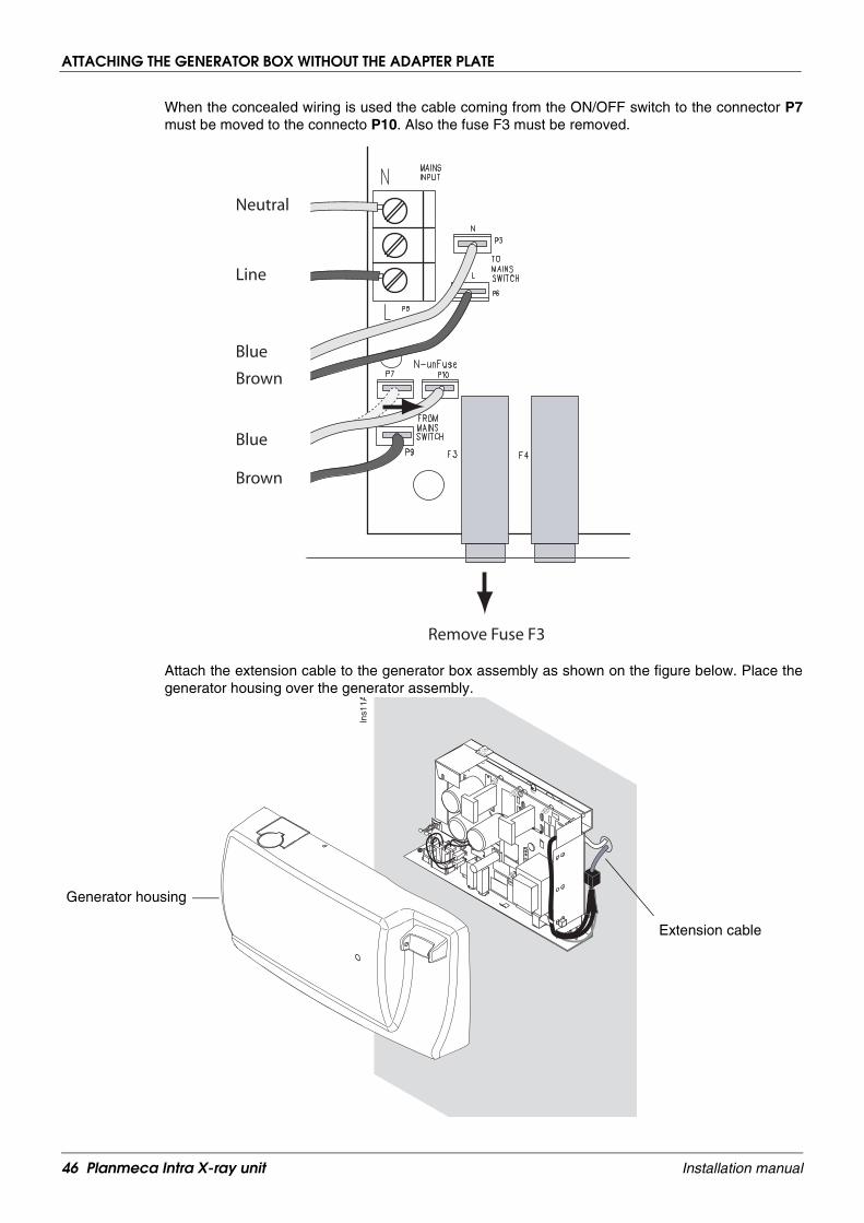
When the concealed wiring is used the cable coming from the ON/OFF switch to the connector P7must be moved to the connecto P10. Also the fuse F3 must be removed.
Attach the extension cable to the generator box assembly as shown on the figure below. Place thegenerator housing over the generator assembly.
Remove Fuse F3
Neutral
Line
Blue
Brown
Blue
Brown
Ins1
1A
Extension cable
Generator housing
46 Planmeca Intra X-ray unit Installation manual

ATTACHING THE GENERATOR BOX WITHOUT THE ADAPTER PLATE
Secure the cover into position with the three M4x6 ULS screws.
Connect the control panel cable to its terminal at the underside of the generator box.I_
15A
PS
U2.
eps
M4x6 ULS
Planmeca Intra X-ray unit 47Installation manual

REMOTE CONTROL PANEL INSTALLATION
7 REMOTE CONTROL PANEL INSTALLATION
WARNING
Ensure that the power supply is switched off before connecting the cables.
NOTE Use the telephone cable (max. 12 m) between the generator box and thedata wall socket.
Attach the frame of the data wall socket to the wall with two ø4x30 DIN 7981 screws. If the wall ismade of concrete or brick, drill ø6 mm (0.23 in.), 32...35 mm (1.25 in.) in depth, holes and place theexpansion anchors into them. If the wall is made of wood or plaster, attach the frame to the wall withtwo ø4x30 DIN 7981 screws to the wall without drilled holes. Do not use the expansion anchors withwooden or plaster wall.
Route the telephone cable through the hole on the side or bottom of the frame. Assemble the datawall socket according to the figure above.
1 2 3 4 5 6 7 8
Possible through holes for the cable
48 Planmeca Intra X-ray unit Installation manual

REMOTE CONTROL PANEL INSTALLATION
Connect the telephone cable according to the figure below.
Install the holder attachment plate to the wall with two ø4x30 DIN 7981 screws. If the wall is made ofconcrete or brick, drill ø6 mm (0.23 in.), 32...35 mm (1.25 in.) in depth, holes and place the expan-sion anchors into them. If the wall is made of wood, attach the screws to the wall without drilledholes.
1 2 3 4 5 6 7 8
P13
2 3 4 5
Rem
con
nec
tors
.ep
s
Generator PCB
Ins1
2.ep
s
Holder attachment plate
ø4x30 DIN 7981 screw Expansion anchor
Wooden wall
Concrete wall
Planmeca Intra X-ray unit 49Installation manual

REMOTE CONTROL PANEL INSTALLATION
Press the control panel holder to the attachment plate. Attach the control panel to the holder andconnect the control panel cable to the control panel and to the wall socket.
NOTE The control panel holder can be attached with a sticker to a surface which cannot be drilled (e.g. glass).
READYPRET
mA
kV
s
BW
SELECT
MODE
Ins1
3.ep
s
50 Planmeca Intra X-ray unit Installation manual

FIXED CONTROL PANEL INSTALLATION
8 FIXED CONTROL PANEL INSTALLATION
8.1 Attaching the bottom plate
NOTE In case you are using a wall socket, attach the bottom plate according toinstructions given in section 8.2 “Attaching the bottom plate to the wallsocket” on page 52.
Use the bottom plate as a template and mark the positions of the holes for the four attaching screwsto the wall.
If the wall is made of concrete or brick, drill ø6 mm (0.23 in.), 32...35 mm (1.25 in.) in depth, holesand place the expansion anchors into them. If the wall is made of wood, attach the screws to thewall without drilled holes. Do not use the expansion anchors with wooden or plaster wall.
Intr
a_bo
x1.e
ps
Bottom plate
4x
Intr
a_bo
x2.e
ps
Telephone cable
Expansion anchor
Use 4 attaching screws
Note: Do not use expansionanchors with wooden/plaster wall.
ø4x30 DIN 7981
Planmeca Intra X-ray unit 51Installation manual

FIXED CONTROL PANEL INSTALLATION
8.2 Attaching the bottom plate to the wall socket
You can also attach the bottom plate to the wall socket as shown on the figure below.
NOTE You can connect the telephone cable to the Extension cable PCB beforeattaching the bottom plate to the wall socket. Refer to section 8.3 “Con-necting the cables” on page 53.
Intr
a_bo
x5.e
ps
Alternative 1
Intr
a_bo
x10.
eps
Alternative 2
Intr
a_bo
x11.
eps
Alternative 3
Bottom plate
Wall socket
Telephone cable
52 Planmeca Intra X-ray unit Installation manual
FIXED CONTROL PANEL INSTALLATION
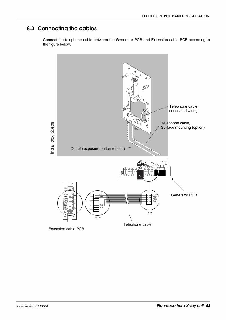
8.3 Connecting the cables
Connect the telephone cable between the Generator PCB and Extension cable PCB according tothe figure below.
Intr
a_bo
x12.
eps
P6
P7
P9
P8
HV1HV1
+12VEXP
KVCGND
AUX1AUX2
SCLELMP
23
45
P6-P9
P13
+12V +12VEXPEXP
GND
GND
SCL
P6
P9
P7
P8
SCL
Telephone cable,
Double exposure button (option)
Telephone cable
Generator PCB
Telephone cable,
Surface mounting (option)
Extension cable PCB
concealed wiring
Planmeca Intra X-ray unit 53Installation manual

FIXED CONTROL PANEL INSTALLATION
In case the double exposure button is installed, connect the cables according to the figure below.
Connect the cross connection (part number 10007597) cable between the Extension cable PCB andfixed control panel.
Intr
a_bo
x13.
eps
P6
P7
P9
P8
HV1HV1
+12VEXP
KVCGND
AUX1AUX2AUX2
SCLELMP
23
45
P6-P9
P13
+12V +12VEXPEXP
GND
GND
SCL
P6
P9
P7
P8
SCL
AUX1
Double exposure button
Generator PCB
Telephone cableDouble exposure button cable
Extension cable PCB
Telephone cable
Intr
a_bo
x4A
.eps
Cross connection cable
Extension cable PCBFixed control panel
54 Planmeca Intra X-ray unit Installation manual

FIXED CONTROL PANEL INSTALLATION
8.4 Attaching the fixed control panel to the bottom plate
In case the telephone cable is routed to the Extension cable PCB via the wall surface, remove thecover from the right-hand side knock-out opening.
Press the fixed control panel to its position so that the mounting pins located on the bottom plate hitthe mounting springs on the control panel. Secure the control panel to its position with one attach-ment screw.
Intr
a_bo
x7.e
ps
Intr
a_bo
x9.e
ps
Planmeca Intra X-ray unit 55Installation manual

EXTERNAL EXPOSURE BUTTON
9 EXTERNAL EXPOSURE BUTTON
An external exposure push button cable can be connected to the Generator PCB according to thefigure below.
Disabling the exposure key on the control panelThe exposure key on the control panel can be disabled as follows.
Enter the service mode: Press and hold down the select key for 4 seconds.
Press and hold down the Mode key for more than 2 seconds, until the four uppermost prepro-grammed setting indicator lights come on.
Press the parameter adjustment up key until the parameter number 18 appears on the kV display.
The number indicating the mode of exposure key operation is shown on the time display. 0 = expo-sure key normal operation, 1 = exposure key operation disabled. The factory default is 0.
Press the Select key until the number starts to blink, and the value can now be changed with theparameter adjustment keys. Select the number 1.
Accept the number 1 setting by pressing the Select key.
Press the Mode key briefly to exit the service mode.
21
34
P13
EXP+12V
GNDSCL
External Exposure Push Button
EE
PB
.eps
Generator PCB
Parameter adjustment up -key18
0
56 Planmeca Intra X-ray unit Installation manual

ATTACHING THE LONG CONE AND RECTANGULAR COLLIMATOR (OPTIONAL)
10 ATTACHING THE LONG CONE AND RECTANGULAR COLLIMATOR (OPTIONAL)
The long cone is attached into its position by pushing it into the short cone and rotate it so that thered point on the short cone and the black point on the long cone are in line.
The rectangular collimator can be attached to the long cone either before the film holder or after it.Refer to the Planmeca Intra X-ray unit’s user’s manual for detailed instructions on how to use therectangular collimator and the film holder.
Attach/remove: red points in line.
In position: red and black points in line.
Rectangular collimator
Film holder
Planmeca Intra X-ray unit 57Installation manual
FINAL ADJUSTMENTS
11 FINAL ADJUSTMENTS
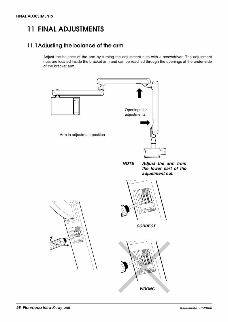
11.1Adjusting the balance of the arm
Adjust the balance of the arm by turning the adjustment nuts with a screwdriver. The adjustmentnuts are located inside the bracket arm and can be reached through the openings at the under-sideof the bracket arm.
Arm in adjustment position
Openings foradjustments
NOTE Adjust the arm fromthe lower part of theadjustment nut.
CORRECT
WRONG
58 Planmeca Intra X-ray unit Installation manual

FINAL ADJUSTMENTS
11.2Adjusting the bracket arm angles
In case the bracket arm angles need to be adjusted it can be done with the limiting plates.
Remove the cover plug from the end of the bracket arm. Attach the limiting plate to the arm with thetwo M3 Allen screws. Adjust the angle with the limiting plate adjustment screws.
Intr
adj2
.eps
Intr
adj1
.eps
Limiting plate
Limiting plate adjustment screw
Planmeca Intra X-ray unit 59Installation manual

FINAL ADJUSTMENTS
11.3Adjusting the stiffness of the tube head’s horizontal axle
Remove the plug from the tube head’s axle and adjust the tightness of the two adjusting screwsevenly (arrows on the figure below).
Ad
j_st
iffn
ess.
eps
WARNING!Do not touch the painted screws
ø 2.5 Allen screw
or the earth spring attachment screw.
60 Planmeca Intra X-ray unit Installation manual

RUNNING IN THE X-RAY UNIT
12 RUNNING IN THE X-RAY UNIT
After installation, before using the unit for the patient work, the following exposures must be taken torun in the unit.
Switch the unit on. The on/off switch is located under the generator box.
• Take three exposures with exposure values 60 kV and 0.05 seconds.
• Take three exposures with exposure values 70 kV and 0.1 seconds.
• Take three exposures with exposure values 70 kV and 1.0 seconds.
Planmeca Intra X-ray unit 61Installation manual


PLANMECA OY Asentajankatu 6, 00880 Helsinki, Finland, tel. +358 20 7795 500fax +358 20 7795 555, e-mail: [email protected], www.planmeca.com