
Installation Manual Pitchglaze Roof Window · tanc 01379 658300 [email protected] 7...
26
Pitchglaze Roof Window Installation Manual
Transcript of Installation Manual Pitchglaze Roof Window · tanc 01379 658300 [email protected] 7...

Pitchglaze Roof WindowInstallation Manual

2Need assistance? 01379 658300 [email protected]
201-INST-Pitchglaze-Installation-Manual-v1.0
Contents
Contents and introduction 2 Delivery 3
Pre Installation 4
Installation 8
Stage 1. Preparation of the aperture 9
Stage 2. Fitting the Pitchglaze 11
Stage 3. Weathering 16
Interior finishing 25

3Need assistance? 01379 658300 [email protected]
201-INST-Pitchglaze-Installation-Manual-v1.0
Delivery
The Pitchglaze unit should arrive on site in undamaged packaging consisting of sterling board edge protection and poly foam to protect the glass. The complete package should be securely wrapped using
Glazing Vision branded packing tape. A separate box containing the installation hardware should be received, and also a second package containing the flashing kit if specified. Please inspect the packaging
and unit and advise Glazing Vision within 48 hours from signing the receipt of your delivery of any damage or shortfall.
Standard Installation Hardware
Enclosed within the hardware box for each unit you should find the following:
Stainless steel countersink woods screws
Low modulus anthracite/grey silicone
Flashing Kit
If a Flashing Kit is specified, the following items should also be included:
Lead sheet: Head flashing (150mm wide) Cill flashing (450mm wide)Lead for soakers (450mm wide)
Roofing underlay:Head apron (1m wide)Jamb aprons (1m wide)
Butyl tape50mm wide

4Need assistance? 01379 658300 [email protected]
201-INST-Pitchglaze-Installation-Manual-v1.0
Pre-Installation
Please ensure all pre-installation checks are carried out prior to commencing installation.
CAUTION!
Pre-Installation Roof Checks
After checking you have received the required installation hardware and product(s) it is important to ensure that the area of installation is suitably prepared. The area surrounding the aperture should be clear
to provide safe access during the installation works. Note that this product is installed from the outside and that suitable provisions should be made for safe handling of the product, including all relevant PPE
and safety systems for working at heights if necessary. The supporting rafters and horizontal trimmers, or alternative support frame for the product, should be checked for specification and dimensional accuracy.
The aperture should be prepared as described below prior to installation.
Preparation of the roof prior to installation will vary depending on roof type and roofing materials. A few common scenarios are included in this manual. Please follow the applicable steps for your configuration.
Glazing Vision strongly recommend a ‘dry run’ (without any silicone) before committing to the final installation.
Sales Drawings
Sales drawings can be obtained by contacting Glazing Vision. The following pages on preparation of the roof recommend the relevant sales drawings for each installation type. Study them carefully before beginning
the installation.
These products can be very heavy. Due consideration should be given to getting the product onto the roof safely and extreme care taken during installation.
Sales drawings should accompany this installation manual. If you do not have them then do not continue the installation without them.

5Need assistance? 01379 658300 [email protected]
201-INST-Pitchglaze-Installation-Manual-v1.0
Preparation of the Roof – Standard Installation
Typically for cold-roof construction – the Pitchglaze will sit directly upon the outside of the rafters.
Sales drawings: Installation (double-glazed) 201-ASS-001 Installation (triple-glazed) 201-ASS-004 Fixing dimensions (both) 201-ASS-007
When preparing rafters, consider how the ends of the battens will be supported at the jambs of the Pitchglaze. Study the sales drawings of the Pitchglaze carefully when designing the size of the aperture. Fig A is for illustrative purposes only and may not be suitable for your installation.
CAUTION!
Before continuing onto the installation instructions:
Pitchglaze to sit on face of rafters and trimmers
Supporting trimmer
Supporting rafter
Fig. A – Example of standard installation
These products can be very heavy. Glazing Vision strongly recommend that a structural engineer is consulted when designing the structure(s) that will support the Pitchglaze and the surrounding roof. Nothing in this manual constitutes a structural proposal.
The surrounding roof should not yet be felted or battened, this will be covered in the installation instructions.
The rafters and horizontal trimmers that will support the Pitchglaze should be complete and in place.

6Need assistance? 01379 658300 [email protected]
201-INST-Pitchglaze-Installation-Manual-v1.0
Preparation of the Roof – Sunken Installation
Typically for cold-roof construction with thin roofing materials, such as slate – the Pitchglaze will sit on the outside of a separate frame sunken below the outside level of the rafters.
Sales drawings: Installation (double-glazed) 201-ASS-002 Installation (triple-glazed) 201-ASS-005 Fixing dimensions (both) 201-ASS-007
Study the sales drawings of the Pitchglaze carefully when designing the size of the main aperture and secondary sunken frame. Fig B is for illustrative purposes only and may not be suitable for your installation.
CAUTION!
Before continuing onto the installation instructions:
Pitchglaze to sit on face of sunken frame
Secondary frame sunken below the level of the rafters
Secondary fillet (see sales drawing)
Fig. B – Example of sunken installation
These products can be very heavy. Glazing Vision strongly recommend that a structural engineer is consulted when designing the structure(s) that will support the Pitchglaze and the surrounding roof. Nothing in this manual constitutes a structural proposal.
The sunken frame that will support the Pitchglaze, and the surrounding rafters and horizontal trimmers should be complete and in place.
The surrounding roof should not yet be felted or battened, this will be covered in the installation instructions.

7Need assistance? 01379 658300 [email protected]
201-INST-Pitchglaze-Installation-Manual-v1.0
Preparation of the Roof – Raised Installation
Typically for warm-roof construction – the Pitchglaze will sit on a frame built up from the rafters.
Sales drawings: Installation (double-glazed) 201-ASS-003 Installation (triple-glazed) 201-ASS-006 Fixing dimensions (both) 201-ASS-007
When preparing rafters, consider how the insulating sarking and the ends of the battens will be supported at the jambs of the Pitchglaze. Study the sales drawings of the Pitchglaze carefully when designing the size of the aperture and packers. Fig C is for illustrative purposes only and may not be suitable for your installation.
CAUTION!
Before continuing onto the installation instructions:
Pitchglaze to sit on face of packers
Packers added to raise the Pitchglaze away from the rafters
Fig. C – Example of raised installation
These products can be very heavy. Glazing Vision strongly recommend that a structural engineer is consulted when designing the structure(s) that will support the Pitchglaze and the surrounding roof. Nothing in this manual constitutes a structural proposal.
The raised frame that will support the Pitchglaze, and the surrounding rafters and horizontal trimmers should be complete and in place.
The insulating sarking (the insulation installed outside the rafters) and the counter battens of the surrounding roof should be complete and in place.
The surrounding roof should not yet be felted or battened, this will be covered in the installation instructions.

8Need assistance? 01379 658300 [email protected]
201-INST-Pitchglaze-Installation-Manual-v1.0
Installation Instructions
Before committing to an installation, Glazing Vision strongly recommend that a ‘dry run’ is completed of the installation process without using silicone.
Note that the installation shown here is a standard installation, using interlocking tiles at 150mm gauge. Other installations differ superficially, but the installation process is similar.
All of the images in this guide are illustrative. They should be used as a reference only, and may not be a true representation of your installation.
Fig. D – Example of standard installation (duplication of Fig. A)
Ensure that you have read and understood the entire Installation Instructions section before commencing your install.
Glazing Vision strongly recommends that the installation is carried out by competent roofers and lead-workers.

9Need assistance? 01379 658300 [email protected]
201-INST-Pitchglaze-Installation-Manual-v1.0
Fig. 1 – Roofing underlay installed and prepared
Cut edge of underlay folded back
Cill fillet (primary)
Fig. 2 – Cill tilting fillet installed
Stage 1 – Preparation of the Aperture
Step 1. Install, trim and finish the roofing underlay (felt or membrane)
• Trim and then fold the underlay back on itself as shown• The underlay should be folded back on the structure that will support the Pitchglaze – see sales drawing• If a sunken installation is used, the secondary fillet should be underneath the underlay – see sales
drawing
Step 2. Install the cill tilting fillet
• Install a tilting fillet as shown (not supplied)• Fix the fillet to the rafters• Glazing Vision recommends a hardwood or treated softwood fillet is used• Consider the distance required between the cill of the Pitchglaze and the fillet (fig.2 – gap A) – see sales
drawing
Gap A

10Need assistance? 01379 658300 [email protected]
201-INST-Pitchglaze-Installation-Manual-v1.0
Step 3. Batten up to the cill
• In addition to normal considerations, consider how the tiling/slates will fit around the Pitchglaze when determining the gauge of the battens
Fig. 3 – Cill battens installed
Cill flashing
Fig. 4 – Cill flashing in positionFlashing length
Step 4. Prepare the cill flashing
• Place the cill flashing as shown• The flashing should be at least 300mm longer than the external width of the Pitchglaze and should be
installed centrally• The flashing should lap under the cill of the Pitchglaze by at least 50mm• Use the cill flashing supplied as part of the flashing kit (if specified), otherwise use Code 4 (nominally
1.8mm thick) flashing lead

11Need assistance? 01379 658300 [email protected]
201-INST-Pitchglaze-Installation-Manual-v1.0
Step 5. Silicone the cill flashing
If performing a dry run, omit the silicone from this step.
• Run a continuous thick bead of silicone along the cill, between the aperture and the cill tilting fillet (fig. 5a)
• Use the silicone supplied as standard with the Pitchglaze
• Place the cill flashing in position - brass or stainless steel nails (not supplied) can be used to tack the lead in place in the area that will be overlapped by the Pitchglaze
• Run a continuous thick bead of silicone along the flashing, up the jambs and across the head as shown (fig. 5b)
Fig. 5a – Cill siliconed for cill flashing
Silicone around head, jambs and cill of aperture
Silicone along cill of aperture
Fig. 5b – Aperture siliconed for Pitchglaze
Stage 2 – Fitting the Pitchglaze

12Need assistance? 01379 658300 [email protected]
201-INST-Pitchglaze-Installation-Manual-v1.0
Step 6. Place the Pitchglaze in position
• Place the Pitchglaze centrally over the aperture (fig. 6a)• Adjust the Pitchglaze to its final position – screws through some of the fixing holes into the rafters below
can be used to temporarily hold the Pitchglaze in place (fig. 6b)• Clean away any excess silicone
Two alternatives are laid out in this step, read both before continuing.
Fig. 6a – Pitchglaze placed in position
Fig. 6b – Fixing holes of Pitchglaze
Fixing holes
These products can be very heavy. Due consideration should be given to getting the product onto the roof safely and extreme care taken during installation.

13Need assistance? 01379 658300 [email protected]
201-INST-Pitchglaze-Installation-Manual-v1.0
• Alternatively, a jig can be fashioned to hold the Pitchglaze in place as shown, refer to the sales drawing for relevant dimensions (fig. 6c & 6d)
Fig. 6c – Example of jig that could be used to place Pitchglaze
Fig. 6d – Close-up of Pitchglaze showing edge to be supported by jig
The fixings holding the jig in place on the roof must not pierce the cill flashing.
The jig must not pinch the cill flashing.
These products can be very heavy. Glazing Vision strongly recommend that a structural engineer is consulted when designing any structure(s) that will support the Pitchglaze. Nothing in this manual constitutes a structural proposal.
Weight of Pitchglaze supported by horizontal member
Example jigSee warnings below
Weight of Pitchglaze supported by jig on this edge - see warnings above

14Need assistance? 01379 658300 [email protected]
201-INST-Pitchglaze-Installation-Manual-v1.0
If performing a dry run, the position of the Pitchglaze can be marked and the Pitchglaze removed. The installation can then begin.
Do not remove any temporary screws that are holding the Pitchglaze in place. Complete this step with the remaining fixing holes. Then remove the temporary screws and repeat this step for those fixing holes. All fixing holes should be siliconed.
Step 7. Fix the Pitchglaze in position
Fill fixing and pilot holes with silicone
Fig. 7a - Injection of silicone
Install fixing screws through wet silicone
Fig. 7b - Fixing screws
Whilst still wet, excess silicone can be removed by spraying on a small amount of soapy water and wiping with a cloth or paper towel.
• Using the Pitchglaze fixing holes as a guide, drill a pilot hole for each fixing screw• Inject silicone through each fixing hole into the pilot hole and between the layers of the folded back
roofing underlay to prevent water ingress• Install and tighten the fixing screws through the wet silicone• Use the silicone and screws supplied as standard with the Pitchglaze
15Need assistance? 01379 658300 [email protected]
201-INST-Pitchglaze-Installation-Manual-v1.0
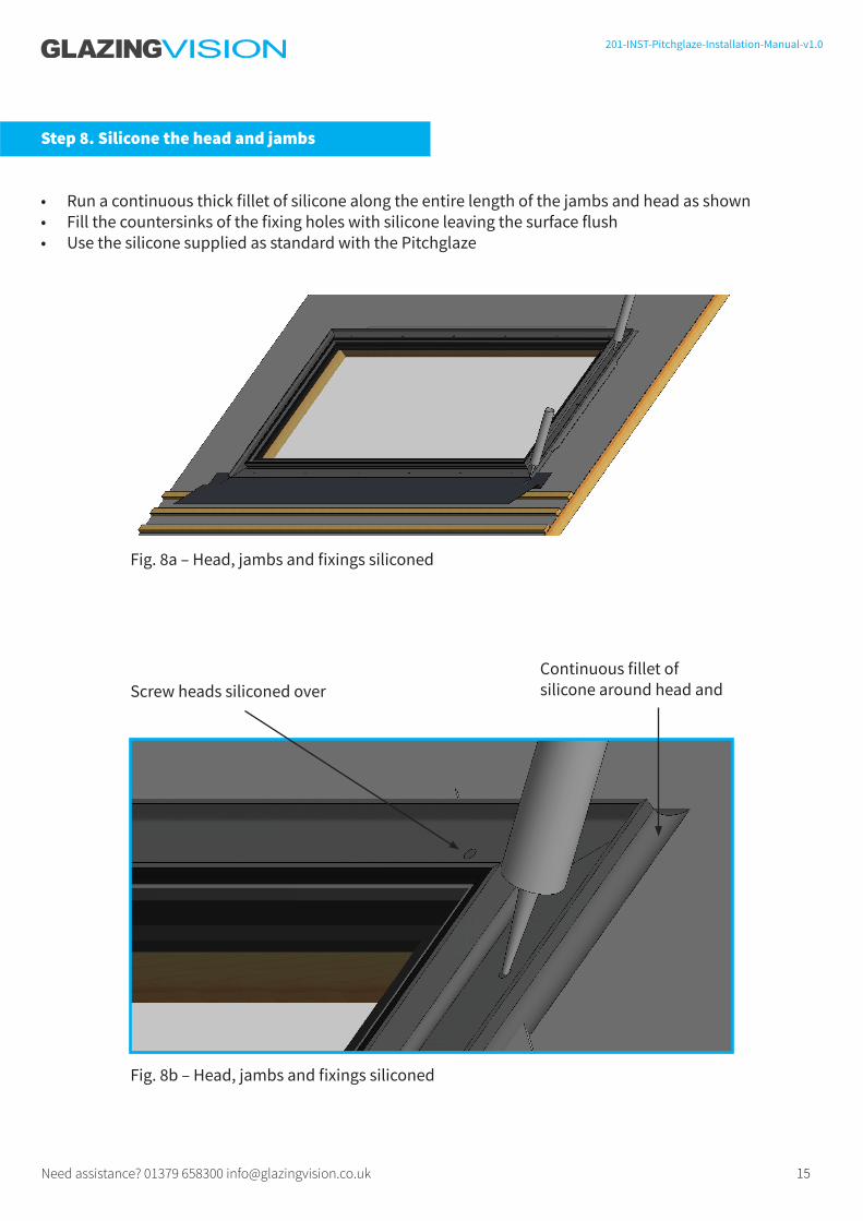
Step 8. Silicone the head and jambs
• Run a continuous thick fillet of silicone along the entire length of the jambs and head as shown• Fill the countersinks of the fixing holes with silicone leaving the surface flush• Use the silicone supplied as standard with the Pitchglaze
Fig. 8a – Head, jambs and fixings siliconed
Fig. 8b – Head, jambs and fixings siliconed
Screw heads siliconed overContinuous fillet of silicone around head and
16Need assistance? 01379 658300 [email protected]
201-INST-Pitchglaze-Installation-Manual-v1.0
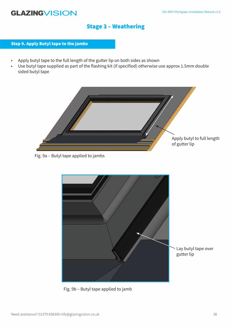
Fig. 9a – Butyl tape applied to jambs
Lay butyl tape over gutter lip
Stage 3 – Weathering
Step 9. Apply Butyl tape to the jambs
• Apply butyl tape to the full length of the gutter lip on both sides as shown• Use butyl tape supplied as part of the flashing kit (if specified) otherwise use approx 1.5mm double
sided butyl tape
Apply butyl to full length of gutter lip
Fig. 9b – Butyl tape applied to jamb

17Need assistance? 01379 658300 [email protected]
201-INST-Pitchglaze-Installation-Manual-v1.0
Step 10. Place the jamb aprons in position
• Place the jamb aprons in position as shown• The apron should be at least 150mm longer than the outside span of the Pitchglaze• The bottom edge of each apron should lap over the cill flashing• The bottom edge of each apron should align with the bottom edge of the Pitchglaze cill• The aprons may be tacked in position to the rafters/counter battens below• For the jamb aprons, use the roofing underlay supplied as part of the flashing kit (if specified) otherwise
use roofing underlay of at least 1m in width
Fig. 10a – Jamb aprons positioned
Difference of at least 150mm
Length of jamb apron
Bottom edge of jamb apron to align with cill edge of Pitchglaze and overlap cill flashing
Fig. 10a – Jamb apron adhered to butyl tape

18Need assistance? 01379 658300 [email protected]
201-INST-Pitchglaze-Installation-Manual-v1.0
Fig. 11 – Jamb battens installed
Fig. 12 – Head tilting fillet
Head fillet
Step 11. Batten up the jambs
• Batten to either side of the Pitchglaze as shown• The battens should be fixed in place ready for tiling/slating
Step 12. Install the head tilting fillet
• Install the tilting fillet as shown (not supplied)• Glazing Vision recommends a hardwood or treated softwood fillet is used• Fix the fillet to the rafters

19Need assistance? 01379 658300 [email protected]
201-INST-Pitchglaze-Installation-Manual-v1.0
Head flashing
Fig. 13a – Head flashing installed
Fig. 13b – Head flashing installed
Head flashing tucked underneath battens
Head flashing tucked into head gutter of Pitchglaze
Step 13. Install the head flashing
• Install the head flashing as shown• The flashing should be at least 300mm longer than the external width of the Pitchglaze and should be
installed centrally• Use the lead flashing supplied as part of the flashing kit (if specified), otherwise use Code 4 (nominally
1.8mm thick) flashing lead

20Need assistance? 01379 658300 [email protected]
201-INST-Pitchglaze-Installation-Manual-v1.0
The head apron must be lapped into the roof underlay as described in this step.Refer to sales drawing for details.
Head apron lapped over head flashing
Fig. 14 – Head apron installed
Step 14. Install the head apron
• Place the head apron in position as shown• The apron should cover the tops of both jamb aprons entirely• The bottom edge of the apron should lap over the head flashing by at least 50mm• The top edge of the apron should lap under the underlay of the roof by at least 50mm• If the underlay supplied/recommended does not reach then a second piece should be used as an
intermediary, lapped over the original piece and lapped under the underlay of the roof• For the roof apron, use the roofing underlay supplied as part of the flashing kit (if specified), otherwise
use roofing underlay of at least 1m in width

21Need assistance? 01379 658300 [email protected]
201-INST-Pitchglaze-Installation-Manual-v1.0
Fig. 15 – Battens above the head installed
Stage 4 – Tiling
Before tiling, take the opportunity to check the weathering (overlap) of the aprons and flashings and to check the silicone sealing the jambs.
Fig. 16 – Cill tiled and cill flashing finished
Step 15. Batten the head
• Batten the roof above the Pitchglaze
Step 16. Tile up to the cill
• Tile up to the batten below the Pitchglaze• Fold and boss the cill flashing into final position

22Need assistance? 01379 658300 [email protected]
201-INST-Pitchglaze-Installation-Manual-v1.0
Fig. 17a – Example of installed soakers for interlocking tiles
Step 17. Prepare the soakers
• The soakers should tuck approximately 100mm between the tiles/slates as shown• The soakers should touch the inside of the hidden gutter of the Pitchglaze as shown• The soakers should overlap by at least 50mm as shown• Use the flashing lead supplied as part of the flashing kit (if specified), otherwise use Code 4 (nominally
1.8mm thick) flashing lead.

23Need assistance? 01379 658300 [email protected]
201-INST-Pitchglaze-Installation-Manual-v1.0
This area to sit between tiles
Flange folded around top of tile to hold soaker in place
This edge to sit in gutter of roof windowBottom end
Top end
Length = gauge + lap of tiles 100mm approx
Glazing Vision strongly recommends that the manufacture and installation of soakers is carried out by a competent lead-worker.
Fig. 17a & 17b are presented only as an example. The soakers described in step 17 may not be suitable for your roof.
Fig. 17b – Example of soaker

24Need assistance? 01379 658300 [email protected]
201-INST-Pitchglaze-Installation-Manual-v1.0
Fig. 18 – Jambs tiled and soakers installed
Fig. 19 – Roof tiled above the head
Step 18. Tile up the jambs
• Tile to either side of the Pitchglaze, installing the soakers
Step 19. Tile the head
• Tile above the Pitchglaze• Glazing Vision recommends that eaves tiles are used immediately above – see sales drawing
Eaves tiles are recommended for use immediately above the Pitchglaze – see sales drawing

25Need assistance? 01379 658300 [email protected]
201-INST-Pitchglaze-Installation-Manual-v1.0
Interior Finishing
The inside edge of the foam tape is designed to remain flush with the surface of the interior finish. Glazing Vision stipulates that the following details are observed when completing your internal finishes:
• The finish must be built out to at least 19mm beyond the aluminium frame of the Pitchglaze.
• No interior metal component (for example edging strips for plastering) may touch or be in close proximity to the aluminium frame of the Pitchglaze.
Contravention of either of these stipulations will severely undermine the thermal efficiency of the Pitchglaze.
Double glazed unit
Powder coated aluminium frame
Surface of internal finish (by others)
Factory applied insulating foam tape
Structural trimmer (by others)
Fig. F– Section detail of double glazed unit - see sales drawing

26Need assistance? 01379 658300 [email protected]
201-INST-Pitchglaze-Installation-Manual-v1.0
For more, refer to the separate declaration of performance documentation, or see the marking affixed to the Pitchglaze.
Conformity
EN 14351-1:2006+A1:2010
For technical support please call01379 658300
or visit us atwww.glazingvision.co.uk/resources or email us [email protected]