
INSTALLATION, MANUAL OPERATION, … -0009500...INSTALLATION, MANUAL OPERATION, MAINTENANCE, AND...
116
INSTALLATION, MANUAL OPERATION, MAINTENANCE, AND PARTS LIST SERIES I MILLING MACHINES EQUIPPED WITH THE ACU-RITE MILLPWR ® CONTROL Manual No. M-492 Litho in U.S.A. Part No. M -0009500-0492 September, 2006 TP6421
Transcript of INSTALLATION, MANUAL OPERATION, … -0009500...INSTALLATION, MANUAL OPERATION, MAINTENANCE, AND...

INSTALLATION, MANUAL OPERATION,MAINTENANCE, AND PARTS LIST
SERIES I
MILLING MACHINES
EQUIPPED WITH THE
ACU-RITE MILLPWR® CONTROL
Manual No. M-492 Litho in U.S.A.Part No. M -0009500-0492 September, 2006
TP6421

Information in this manual is subject to change without notice.
This manual covers installation, manual operation, maintenance, and partslist for Series I milling machines equipped with the Acu-Rite MILLPWR® control.
Refer to the Acu-Rite MILLPWR control manual supplied with the machinefor information relating to automatic machine operation.
In no event will Hardinge Inc. be responsible for indirect or consequentialdamage resulting from the use or application of the information in this manual.
Reproduction of this manual, in whole or in part, without written permission ofHardinge Inc. is prohibited.
ORDERING REPLACEMENT PARTS
Please provide the following information when ordering replacement parts:
1. The complete machine serial number. The machine serial number tag is located on the powercase door.
2. List the following:
A) Manual Number (M-492).
B) Page Number.
C) Item Number.
D) Part Description.
E) Part Number.
F) Quantity of each part required.
3. Specify how and where to ship.
- NOTICE -
Bridgeport is a registered trademark of Hardinge Inc.
© 2006, Hardinge Inc. M-492

SAFETY
To prevent serious bodily injury, you should observe the following basic safety precautions wheninstalling, operating, or servicing the milling machine.
• Follow all instructions in the manual.
• Wear approved industrial safety glasses and safety shoes.
• Do not wear gloves, long sleeves, long hair, rings, watches, jewelry or other items that couldbecome caught in moving parts.
• Keep all parts of your body away from moving parts (belts, cutters, gears, etc.)
• Use proper point of operation safeguarding.
These and other safety precautions are discussed in the American National Standard Institutestandard entitled safety requirements for the construction, care, and use of drilling, milling, and boringmachines (ANSI B11.8-2001).
This publication is available from:
American National Standards Institute25 West 43rd Street, 4th floor
New York, NY 10036
- or -
www.ansi.org
To assist machine users in designing point of operation safeguarding for their specific machine ap-plications, the Occupational Safety And Health Administration has published a booklet entitled Con-cepts and Techniques of Machine Safeguarding (O.S.H.A. Publication No. 3067).
This publication is available from:
The Publication Office – O.S.H.A.U.S. Department of Labor
200 Constitution Avenue, NWWashington, D.C. 20210
- or -
www.osha.gov
The general purpose point of operation shield provided with this machine and shown in certain illus-trations throughout this manual may not be appropriate and cannot be utilized for all possible applica-tions of the machine. Use additional or alternate safeguarding where this shield is not appropriate orcannot be utilized. Note that for purposes of display, the shield has been removed in certain otherillustrations in this manual.
M-492 i

WARNINGS, CAUTIONS, AND NOTES
- WARNINGS -
Warnings must be followed carefully to avoid the possibility of personal in-jury or damage to the machine, tooling, or workpiece.
- CAUTIONS -
Cautions must be followed carefully to avoid the possibility of damage to themachine, tooling, or workpiece.
In situations where inattention could cause either personal injury or damage to the equipment, awarning notice is used.
- NOTES -
Notes contain supplemental information.
This document is intended for the use of those who install, operate, and maintain the milling ma-chine. Although reasonable care has been exercised in the preparation of this manual to make it com-plete and accurate, this manual does not purport to cover all conceivable problems or applicationspertaining to this machine.
ii M-492

SAFETY RECOMMENDATIONS
DO NOT OPERATE EQUIPMENT until you have read and understood the appropriate opera-tor and safety maintenance manuals.
DO NOT OPERATE EQUIPMENT until you have read and understood all machine and con-trol key signs.
DO NOT OPERATE EQUIPMENT for the first time without a qualified instructor. Consult yoursupervisor when in doubt as to the correct way to perform an operation.
DO NOT OPERATE EQUIPMENT unless proper maintenance has been regularly performedand the equipment is known to be in good working order.
DO NOT ALLOW the operation or repair of equipment by untrained personnel.
WARNING or INSTRUCTION TAGS are mounted on the equipment for your safety and infor-mation. Do not remove them.
DO NOT OPERATE EQUIPMENT if any unusual or excessive heat, noise, smoke, or vibra-tion occurs. Report any excessive or unusual vibration, sounds, smoke, or heat as well as anydamaged parts.
WEAR SAFETY GLASSES with side shields and SAFETY SHOES with steel toes and oil-re-sistant soles at all times. When necessary, wear respirator, helmet, and ear muffs or plugs.
DO NOT OPERATE ANY MACHINE while wearing rings, watches, jewelry, loose clothing,neckties, or long hair not contained by a net or shop cap.
DO NOT WEAR GLOVES while operating equipment. Gloves are easily caught in movingparts.
REMOVE ANY LOOSE PARTS OR TOOLS left on machine or in the work area before oper-ating the machine. Always check the machine and work area for loose tools and parts, espe-cially after work has been completed by maintenance personnel.
REMOVE CHUCK WRENCHES before starting the machine.
NEVER OPERATE A MACHINE after taking strong medication, using non-prescription drugsor consuming alcoholic beverages.
SAFEGUARD THE CUTTING ZONE (“point of operation”). Use standard, general purposesafeguards when possible. Use special safeguards when required.
PROTECT YOUR HANDS. Stop the spindle completely before changing tools.
PROTECT YOUR HANDS. Stop the spindle completely before loading or unloading aworkpiece.
DO NOT REMOVE CHIPS with hands. Use a hook or similar device and make certain that allmachine movements have ceased.
DO NOT ADJUST tooling, workpieces or coolant hoses while the machine is running.
PROTECT YOUR HANDS. Stop the spindle completely before taking measurements.
PROTECT YOUR HANDS. Stop the spindle completely before opening safeguards or covers.
NEVER REACH around a safeguard.
M-492 iii
PROTECT YOUR HANDS. Stop the machine before changing or adjusting belts, pulleys orgears.
PROTECT YOUR HANDS. Keep hands and arms clear of spindle start switch when changingtools.
PROTECT YOUR EYES AND THE MACHINE. Never use a compressed air hose to removechips.
KEEP WORK AREA WELL LIGHTED. ask for additional light if needed.
DON’T SLIP. Keep your work area clean and dry. Remove chips, oil and obstacles.
NEVER LEAN ON your machine. Stand away when the machine is running.
MAKE CERTAIN that you are clear of any “pinch points” created by moving slides beforestarting the machine.
PREVENT OBJECTS from flying loose. Securely clamp and locate workpiece. Use stopblocks where necessary. Keep clamps clear of cutter path.
PREVENT CUTTER BREAKAGE. Use correct table feed and spindle speed for the job. Re-duce feed and speed if you notice unusual noise or vibration.
PREVENT CUTTER BREAKAGE. Rotate spindle in clockwise direction for right-hand tools,counterclockwise for left-hand tools. Use the correct tool for the job.
PREVENT WORKPIECE and cutter damage. Never start the machine when the cutter is incontact with the workpiece.
DO NOT USE worn or defective tools. Use the proper size and type of tool for the task athand.
KEEP ROTATING CRANKS AND HANDWHEELS well lubricated and maintained. Do not re-move safety springs.
CERTAIN MATERIALS, such as magnesium, are highly flammable in dust and chip form. Seeyour supervisor before working with these materials.
PREVENT FIRE. Keep flammable liquids and materials away from work area and hot chips.
PREVENT MACHINE from moving unexpectedly. Disengage power feed when not being used(manual machines only).
PREVENT MACHINE from moving unexpectedly. Always start machine in manual mode.
UNLESS OTHERWISE NOTED, all operating and maintenance procedures are to be per-formed by one person. To avoid injury to yourself and others, be sure that all personnel areclear of the machine when opening or closing the coolant guard door and any access covers.
iv M-492

INSTALLATION AND USE OF SAFEGUARDS
Both American National Standard B11.8 and OSHA Section 1910.212 assign responsibility forpoint of operation safeguarding of milling machines to the employer/user. Therefore, to prevent seri-ous injury resulting from the rotating cutter, flying chips, or splashing coolant, point of operation safe-guarding should be used on milling machines to the greatest extent practicable.
This booklet provides basic information for the installation and use of the general purpose safe-guard. It also contains the names of several manufacturers of other types of point of operation safe-guarding for vertical milling machines.
Remember, point of operation safeguarding is your responsibility as the employer/user. You are inthe best position to evaluate your safeguarding needs and ensure that the proper safeguards are in-stalled and used.
- CAUTION -
A safety shield is supplied for protection from chips and coolant with everymachine.
The chip and coolant shields have been designed and are custom manufac-tured with the highest clear impact material commercially available:polycarbonate (G.E. Lexan). It has an impact strength 5 to 10 times greaterthan acrylic (plexiglass) or butyrate (UVEX) materials, thereby offering thegreatest protection for our customers.Some of the new “easy to dispose of” coolants and/or cutting oils containchemicals harmful to polycarbonate. These chemicals are:Mono-ethanolamine, Di-ethanolamine, Tri-ethanolamine and the combinationthereof. These chemicals may significantly reduce the impact strength of theshield within days, and could destroy the entire shield in weeks.
Use of use of coolants and/or cutting oils containing these chemicals willvoid the warranty on your safety shield, and could cause injury to your work-ers.
- WARNING -
This safeguard DOES NOT take the place of any other safety practice orsafety equipment.
YOU MUST ALWAYS wear safety glasses and safety shoes.
YOU MUST ALWAYS stop the spindle of the machine completely beforechanging or adjusting the workpiece, fixture, or tool.
YOU MUST NEVER wear gloves, long sleeves, long hair, rings, watches,neckties, jewelry or other loose items.
M-492 v
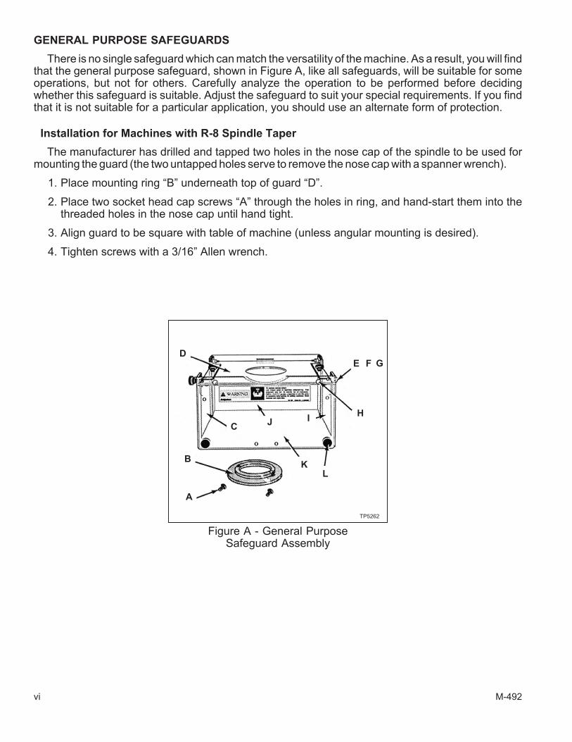
GENERAL PURPOSE SAFEGUARDS
There is no single safeguard which can match the versatility of the machine. As a result, you will findthat the general purpose safeguard, shown in Figure A, like all safeguards, will be suitable for someoperations, but not for others. Carefully analyze the operation to be performed before decidingwhether this safeguard is suitable. Adjust the safeguard to suit your special requirements. If you findthat it is not suitable for a particular application, you should use an alternate form of protection.
Installation for Machines with R-8 Spindle Taper
The manufacturer has drilled and tapped two holes in the nose cap of the spindle to be used formounting the guard (the two untapped holes serve to remove the nose cap with a spanner wrench).
1. Place mounting ring “B” underneath top of guard “D”.
2. Place two socket head cap screws “A” through the holes in ring, and hand-start them into thethreaded holes in the nose cap until hand tight.
3. Align guard to be square with table of machine (unless angular mounting is desired).
4. Tighten screws with a 3/16” Allen wrench.
vi M-492
Figure A - General PurposeSafeguard Assembly
E
BK
JC
I
L
A
D
H
F G
TP5262

Machines with Erickson #30 Quick Change or Universal #200 Quick Change Spindles
If your milling machine attachment has either an Erickson #30 or a Universal #200 quick changespindle, the manufacturer has drilled and tapped four #8-32 holes in the nose cap of the spindle formounting the guard.
ERICKSON SPINDLE
If the nose cap mounting ring has not been installed, the following procedure will apply:
1. Remove the spindle locknut. This is done by removing the long button head black finish screw,which is normally left of the cadmium-finished button head screw on the locknut of the spindle.This will allow you to unscrew the locknut by turning it counter-clockwise.
2. Place the nose cap mounting ring “O”, Figure B, up against the quill nose cap and install the fourbutton head cap screws “M”.
- NOTE -
The counterbored side of the nose cap mounting ring fits against the nose cap.
3. Lower the quill. Place the clamping ring “P” underneath the top of the guard “Q” and position theguard under the spindle.
4. Install the four socket head cap screws “N” through the nose cap mounting ring and threadthem into the clamping ring.
5. Align the front of the guard parallel to the front of the table. Tighten the screws clamping theguard in position.
6. Reinstall the quick change locknut. Refer to assembly instructions.
If the nose cap mounting ring has been installed, omit steps 1, 2, and 6.
UNIVERSAL #200 QUICK CHANGE SPINDLES
The quick change locknut is not to be removed. To install the spindle safeguard, follow the preced-ing steps listed above: 2, 3, 4 and 5.
M-492 vii
Figure B - Spindle Guard Assembly
N
P
TP5263
O
M
Q

R-8 Shield Assembly
ITEM PART NUMBER DESCRIPTION QTY
A 11011031 Screw, Socket Hd Cap, .250”-20 x .625” 2
B 12191201 Ring, Guard 1
C 11191204 Shield, Left Side 1
D 11191206 Shield Assy, Top 1
E 11665810 Screw, Button Hd Cap, #10-32x.750” 3
F 11010065 Washer, Plastic, #10-32 8
G 11010055 Nut, Stop, Plastic, #10-32 3
H 11010063 Screw, Drive, Type U, #12 x .625” 2
I 11191205 Shield, Right Side 1
J 11191203 Assembly, Rear Shield 1
K 11121202 Assembly, Front Shield 1
L 11010056 Screw, Hand, #10-32 x .750” 4
Quick Change Shield Assembly
ITEM PART NUMBER DESCRIPTION QTY
A 11011031 Screw, Socket Hd Cap, .250”-20 x .625” 2
C 11191204 Shield, Left Side 1
E 11665810 Screw, Button Hd Cap, #10-32x.750” 3
F 11010065 Washer, Plastic, #10-32 8
G 11010055 Nut, Stop, Plastic, #10-32 3
H 11010063 Screw, Drive, Type U, #12 x .625” 2
I 11191205 Shield, Right Side 1
J 11191203 Assembly, Rear Shield 1
K 11121202 Assembly, Front Shield 1
L 11010056 Screw, Hand, #10-32 x .750” 4
M 11651199 Screw, Button Hd Cap, #10-32 x .500” 4
N 11980224 Screw, Socket Hd Cap, #8-32 x .625” 4
O 12190330 Ring, Guard 1
P 12190331 Ring, Guard 1
Q 11191207 Shield Assy, Top 1
viii M-492

- NOTES -
M-492 ix

- NOTES -
x M-492

Table of Contents
CHAPTER 1 - INSTALLATIONUncrating . . . . . . . . . . . . . . . . . . . . . . . . . . . . . . . . . . . . 1-1
Shortages . . . . . . . . . . . . . . . . . . . . . . . . . . . . . . . . . . . . 1-1
Cleaning . . . . . . . . . . . . . . . . . . . . . . . . . . . . . . . . . . . . 1-1
Installation . . . . . . . . . . . . . . . . . . . . . . . . . . . . . . . . . . . 1-2Handles . . . . . . . . . . . . . . . . . . . . . . . . . . . . . . . . . . . 1-2Positioning Head Upright . . . . . . . . . . . . . . . . . . . . . . . . . . . 1-2
Handling . . . . . . . . . . . . . . . . . . . . . . . . . . . . . . . . . . . . 1-3Lifting the Machine . . . . . . . . . . . . . . . . . . . . . . . . . . . . . . 1-3Tightening Sequence . . . . . . . . . . . . . . . . . . . . . . . . . . . . . 1-4
Foundation . . . . . . . . . . . . . . . . . . . . . . . . . . . . . . . . . . . 1-4Placing on Solid Foundation . . . . . . . . . . . . . . . . . . . . . . . . . . 1-4Leveling Machine . . . . . . . . . . . . . . . . . . . . . . . . . . . . . . . 1-5
Machine Power Supply. . . . . . . . . . . . . . . . . . . . . . . . . . . . . . 1-6Connecting the Power Supply . . . . . . . . . . . . . . . . . . . . . . . . . 1-6
Lubrication . . . . . . . . . . . . . . . . . . . . . . . . . . . . . . . . . . . 1-7
Initial Set Up . . . . . . . . . . . . . . . . . . . . . . . . . . . . . . . . . . 1-8Alignment of Head for Fine Work . . . . . . . . . . . . . . . . . . . . . . . 1-8Tightening Sequence . . . . . . . . . . . . . . . . . . . . . . . . . . . . . 1-8Lubrication . . . . . . . . . . . . . . . . . . . . . . . . . . . . . . . . . . 1-8
CHAPTER 2 - MANUAL OPERATIONHead Controls . . . . . . . . . . . . . . . . . . . . . . . . . . . . . . . . . . 2-1
Spindle Speed Ranges . . . . . . . . . . . . . . . . . . . . . . . . . . . . 2-1Speed Range Selector (Hi-Neutral-Lo Lever) . . . . . . . . . . . . . . . . 2-2Variable Speed Dial . . . . . . . . . . . . . . . . . . . . . . . . . . . . 2-2Changing Speed Within Range . . . . . . . . . . . . . . . . . . . . . . . 2-3Changing from Direct Drive (Hi) to Back Gear Drive (Lo) . . . . . . . . . . . 2-3Changing from Back Gear Drive (Lo) to Direct Drive (Hi) . . . . . . . . . . . 2-3
High-Low Range Switch. . . . . . . . . . . . . . . . . . . . . . . . . . . . 2-4Spindle Brake . . . . . . . . . . . . . . . . . . . . . . . . . . . . . . . . 2-4Quill . . . . . . . . . . . . . . . . . . . . . . . . . . . . . . . . . . . . . 2-5
Quill Feed Handle . . . . . . . . . . . . . . . . . . . . . . . . . . . . . 2-5Manual Feed Handwheel (2-Axis Machine Only) . . . . . . . . . . . . . . . 2-6Quill Power Feed Transmission Lever (2-Axis Machine Only) . . . . . . . . . 2-7Quill Feed Reverse Knob (2-Axis Machine Only) . . . . . . . . . . . . . . . 2-8Quill Feed Control Lever (2-Axis Machine Only) . . . . . . . . . . . . . . . 2-8Quill Feed Overload Clutch. . . . . . . . . . . . . . . . . . . . . . . . . 2-8Quill Feed Selector (2-Axis Machine Only) . . . . . . . . . . . . . . . . . 2-8Quill Micrometer Nut and Stop Knob (2-Axis Machine Only) . . . . . . . . . 2-9Quill Lock . . . . . . . . . . . . . . . . . . . . . . . . . . . . . . . . . 2-9
M-492 1
Spindle Draw Bar . . . . . . . . . . . . . . . . . . . . . . . . . . . . . . . . 2-10
Head Adjustments . . . . . . . . . . . . . . . . . . . . . . . . . . . . . . . . 2-11Swiveling the Head . . . . . . . . . . . . . . . . . . . . . . . . . . . . . . 2-11Tilting the Head . . . . . . . . . . . . . . . . . . . . . . . . . . . . . . . 2-11Rotating the Head . . . . . . . . . . . . . . . . . . . . . . . . . . . . . . 2-12
Turret Adjustment . . . . . . . . . . . . . . . . . . . . . . . . . . . . . . . . 2-13
Ram Adjustment . . . . . . . . . . . . . . . . . . . . . . . . . . . . . . . . . 2-13
Saddle Clamping . . . . . . . . . . . . . . . . . . . . . . . . . . . . . . . . 2-14
Table Clamping . . . . . . . . . . . . . . . . . . . . . . . . . . . . . . . . . 2-14
Knee Clamping . . . . . . . . . . . . . . . . . . . . . . . . . . . . . . . . . 2-14
CHAPTER 3 - MAINTENANCEHead . . . . . . . . . . . . . . . . . . . . . . . . . . . . . . . . . . . . . . 3-1
Motor Removal . . . . . . . . . . . . . . . . . . . . . . . . . . . . . . . . 3-1Drive Belt Replacement . . . . . . . . . . . . . . . . . . . . . . . . . . . . 3-2Timing Belt Replacement . . . . . . . . . . . . . . . . . . . . . . . . . . . 3-2Brake Shoe Replacement . . . . . . . . . . . . . . . . . . . . . . . . . . . 3-3
Z Axis and Spindle. . . . . . . . . . . . . . . . . . . . . . . . . . . . . . . . 3-4Micro Feed Trip Assembly and Quill Removal . . . . . . . . . . . . . . . . . 3-4Balance Spring Replacement . . . . . . . . . . . . . . . . . . . . . . . . . 3-5Feed Trip Adjustment . . . . . . . . . . . . . . . . . . . . . . . . . . . . . 3-5Collet Aligning Screw Replacement . . . . . . . . . . . . . . . . . . . . . . 3-6
Table Gib Adjustment . . . . . . . . . . . . . . . . . . . . . . . . . . . . . . 3-7
Saddle Gib Adjustment . . . . . . . . . . . . . . . . . . . . . . . . . . . . . . 3-9
Knee Gib Adjustment . . . . . . . . . . . . . . . . . . . . . . . . . . . . . . 3-11
CHAPTER 4 - PARTS LISTINGS2J-Head Top Housing . . . . . . . . . . . . . . . . . . . . . . . . . . . . . . 4-1
2J-Head Back Gear . . . . . . . . . . . . . . . . . . . . . . . . . . . . . . . 4-4
2J-Head Lower Housing . . . . . . . . . . . . . . . . . . . . . . . . . . . . . 4-7
Basic Machine. . . . . . . . . . . . . . . . . . . . . . . . . . . . . . . . . . 4-12
Spray Mist . . . . . . . . . . . . . . . . . . . . . . . . . . . . . . . . . . . 4-16
Flood Coolant . . . . . . . . . . . . . . . . . . . . . . . . . . . . . . . . . . 4-17
Lubrication System . . . . . . . . . . . . . . . . . . . . . . . . . . . . . . . 4-18
Acu-Rite Millpwr Control Components . . . . . . . . . . . . . . . . . . . . . . . 4-20X Axis Handle Assembly . . . . . . . . . . . . . . . . . . . . . . . . . . . 4-20X Axis Motor Assembly . . . . . . . . . . . . . . . . . . . . . . . . . . . . 4-22Y Axis Motor Assembly . . . . . . . . . . . . . . . . . . . . . . . . . . . . 4-24Z Axis Assembly (View 1) . . . . . . . . . . . . . . . . . . . . . . . . . . . 4-26Z Axis Assembly (View 2) . . . . . . . . . . . . . . . . . . . . . . . . . . . 4-28Z Axis Assembly (View 3) . . . . . . . . . . . . . . . . . . . . . . . . . . . 4-30Z Axis Assembly (View 4) . . . . . . . . . . . . . . . . . . . . . . . . . . . 4-32
2 M-492

Control Mounting Bracket . . . . . . . . . . . . . . . . . . . . . . . . . . . 4-34Spindle Control Case (View 1). . . . . . . . . . . . . . . . . . . . . . . . . 4-36Spindle Control Case (View 2). . . . . . . . . . . . . . . . . . . . . . . . . 4-38Spindle Control Case (View 3). . . . . . . . . . . . . . . . . . . . . . . . . 4-40Spindle Control Case (View 4). . . . . . . . . . . . . . . . . . . . . . . . . 4-42Spindle Control Case (View 5). . . . . . . . . . . . . . . . . . . . . . . . . 4-44Spindle Control Case (View 6). . . . . . . . . . . . . . . . . . . . . . . . . 4-46Spindle Control Case (View 7). . . . . . . . . . . . . . . . . . . . . . . . . 4-48Speed Control Pendant . . . . . . . . . . . . . . . . . . . . . . . . . . . . 4-50
CHAPTER 5 - SPECIFICATIONSPrinciple Dimensions. . . . . . . . . . . . . . . . . . . . . . . . . . . . . . . 5-1
Floor Plan Installation Layout . . . . . . . . . . . . . . . . . . . . . . . . . . . 5-2
Machine Specifications . . . . . . . . . . . . . . . . . . . . . . . . . . . . . . 5-4
Head Specifications . . . . . . . . . . . . . . . . . . . . . . . . . . . . . . . 5-5
General Speed Recommendations . . . . . . . . . . . . . . . . . . . . . . . . 5-6
Table of Cutting Speeds and Feeds . . . . . . . . . . . . . . . . . . . . . . . . 5-6
M-492 3

- NOTES -
4 M-492

CHAPTER 1 - INSTALLATION
UNCRATING
Carefully remove protective crating and skids so that the machine and parts are not marred,scratched or impaired. In the event of damage having occurred during transit, communicate at oncewith our representative and the transportation company making delivery.
SHORTAGES
Check shipment carefully against the itemized packing list which is included in the parts box. Incase of shortages, report them immediately to the representative from whom the machine was pur-chased, indicating the parts not received which have been checked on the packing list.
CLEANING
Thoroughly clean protective coating from the machine with a suitable cleaning solution.
- WARNING -
DO NOT use gasoline or any other flammable cleaning agent to clean machine.
- NOTE -
Do not move the table, saddle, knee, orany moveable part until all ways havebeen well cleaned and lubricated.
1. After initial cleaning, move table, saddle andknee in one direction by hand to limit stop.
2. Clean and lubricate the exposed ways.
3. Move each unit to the opposite limit stop, andclean and lubricate the exposed ways.
4. Move each unit to the opposite stop once moreand similarly clean and lubricate the exposedways.
5. Loosen bolts to unlock the ram, and move itforward and backward to the full length in orderto clean and lubricate.
M-492 1-1
Figure 1.1 - Milling MachineLeft Side View
TP5277

INSTALLATION
If delivery of your machine is made with the milling head in an upside-down position, follow the in-structions below to prepare your machine for operation.
HANDLES
For shipping purposes, the hand cranks are inverted to face the machine. To reverse them, engagethe lock mechanism to the saddle and table. Using a (1-inch) wrench, remove the retaining lead screwnut and install the hand cranks properly.
POSITIONING HEAD UPRIGHT
Loosen four locknuts “C”, Figure 1.3, and pull stop pin “A”, Figure 1.2, out to detent and rotate headattachment using the swivel bolt “B”, Figure 1.3, in either direction until it has been moved within ap-proximately 20% of vertical. It is recommended supporting the head by hand to relieve the weight onthe swivel bolt, as a safety precaution, push the stop pin back in. Continue to raise the head attach-ment to vertical position. Align the indicator on the head attachment with the ZERO line on the ramadapter scale. Tighten all nuts first to 25 lb-ft torque in a diagonal sequence, then to 50 ft/lbs.
- NOTE -
Care should be taken to avoid excessive pressure since this will cause distortion inthe quill.
1. Lower knee approximately 6” (150mm).
2. Withdraw the safety pin on the left-hand side of ram adapter.
3. Loosen the four unit head mounting bolts.
4. Support unit head manually and use a spanner on swivel bolt to wind into upright position.
5. Press the safety pin back into the ram adapter after passing the 25� mark.
6. Tighten the four unit head mounting bolts; first to 25 lb-ft in a diagonal sequence, then to 50 lb-ft.
1-2 M-492
Figure 1.2 - Positioning the Head(Left View)
Swiveling Head
To Swivel the Head More Than 25�,
Safety Pin “A” Must be Pulled Outwards
A
TP5278A
Figure 1.3 - Positioning the Head(Front View)
B
Table
Aligning
Faces
C
TP5278B

HANDLING
LIFTING THE MACHINE
- WARNING -
BE SURE to use proper sling when lifting. Improper lifting could cause seri-ous injury.
Note position of ram and table when lifting with sling. Machine should be lifted by placing a sling un-der the ram as illustrated in Figure 1.4.
M-492 1-3
Figure 1.4 - Lifting the Machine
TP5279

TIGHTENING SEQUENCE
Tighten bolts first to 25 lb-ft torque in a diagonal sequence as noted in Figure 1.5, then to 50 lb-ft.Overtightening could cause binding in the quill movement.
FOUNDATION
PLACING ON SOLID FOUNDATION
When setting machine on a concrete foundation, it is advisable to use a little grout (thin mortar) totake care of any unevenness in the concrete as well as to provide a solid foundation at all points.
When setting machine on a floor than has any surface irregularities, shims should be used to cor-rect this condition to the greatest extent possible.
- NOTE -
It is recommended that the machine be secured to the floor to prevent movement ortipping due to off-center loading.
1-4 M-492
Figure 1.5 - Tightening Sequence
1
4
3
2
TP5280

Before securing machine to floor by tighteninghold-down bolts, make certain that all four cor-ners are making contact with the floor after ma-chine is leveled. If above condition is not met, it ispossible to twist the column and but a bind intoways.
Ideally all milling machines should be bolted toa concrete foundation. The machine should beplaced on a solid level floor with shims or anti-vi-bration pads as shown in Figure 1.6 to insure ma-chine base is positioned evenly.
LEVELING MACHINE
Set machine by leveling the work table length-wise and crosswise with a precision instrument asshown in Figure 1.7.
M-492 1-5
Figure 1.6 - Foundation
Shim
TP5281
Figure 1.7 - Leveling the Machine
Level
Level
TP5282

MACHINE POWER SUPPLY
- WARNING -
The power connection must be performed by a qualified electrician.
CONNECTING THE POWER SUPPLY
To connect the machine to the plant supply, have a qualified electrician proceed as follows:
1. Check required voltage against power supply to ensure that they are compatible.
2. Connect machine wiring to power supply making sure connection is in compliance with safetyregulations.
3. Check for correct spindle rotation. In the HIGH SPEED range, the spindle should rotateclockwise when viewed from the top of the machine.
- NOTE -
The drum switch and hi-neutral-lo lever must be in hi range when checking spindlerotation.
1-6 M-492

LUBRICATION
Indicator Lubrication Area Type of Lubrication
1 Way Surfaces and Lead Screws Sunoco Waylube #1180 or equivalent
2 Milling Heads (Spindle Bearings)S.A.E. 10 or 10W Light Oil(None on grease-packed heads)
3 Motor None required. Motor greased for life of bearings
4 Vari-DriveGrease with lubricate every six months as described onlubrication plate
Not Shown Power Feed Oil to sight level with Mobilube No. 46 S.A.E. 140
Not Shown Shaping Attachment Mobil 600W Oil or equivalent
M-492 1-7
Figure 1.8 - Lubrication Requirements
1
Lubrication
Instruction Plate
3
2
4
TP5283
Recommended Lubrication
Few Drops Twice Daily

INITIAL SET UP
ALIGNMENT OF HEAD FOR FINE WORK
For precision boring or work of that nature, where it is necessary to have the head perfectly squarewith the table, use method described below. To set head perfectly square with table, adjust ramadapter through vertical adjusting worm shaft with ram adapter on ram. Loosen four locknuts butleave drag on same for fine adjustment. To square head to table in the longitudinal axis, mount indica-tor as shown in Figure 1.9. For general milling use, graduations provided on the head are closeenough.
TIGHTENING SEQUENCE
Tighten the four head locknuts in a diagonal order as previously described on Page 1-4. Tighten thethree ram locking bolts to 50 lb-ft.
LUBRICATION
Do not operate machine until properly lubricated.
1-8 M-492
Figure 1.9 - Head Alignment for Y- and X-Axis
Adjustable
Worm Shaft
Head Alignment Y-Axis Head Alignment X-Axis
Zero ZeroZero Zero
3 Ram
Locking Bolts Vertical Adjustable
Worm Shaft
Ram Adapter
Ram
Locknuts
Aligning
Faces
TP5284

- NOTES -
M-492 1-9

- NOTES -
1-10 M-492

CHAPTER 2 - MANUAL OPERATION
- NOTE -
Refer to the Acu-Rite MILLPWR® control manual supplied with the machine for infor-mation relating to automatic machine operation.
HEAD CONTROLS
SPINDLE SPEED RANGES
The machine has two spindle speed ranges:
• LOW RANGE (60-500 rpm), which isobtained through the back-gear drive.
• HIGH RANGE (500-4200 rpm), which isobtained through direct drive.
Three controls are used to establish spindlespeeds:
• The HI-NEUTRAL-LO lever, Figure 2.1
• The High-Low Range switch. Refer to page2-4 for information on the High-Low Rangeswitch.
• Speed Change handwheel "B", Figure 2.2.
M-492 2-1
Figure 2.1 - HI-NEUTRAL-LO Lever
NEUTRAL
HI LO
SecuringScrews
TP5362A
Figure 2.2 - Variable Speed Dialand Speed Change Handwheel
A
BTP5367

Speed Range Selector (Hi-Neutral-Lo Lever)
At the lower right side of the spindle housing is the HI-NEUTRAL-LO lever, shown in Figure 2.1.This lever is used to set the speed range for the spindle motor.
It has three positions for the spindle motor gearing:
• Low
• Neutral
• High
Neutral is provided to permit free spindle rotation for indicating and set-up work. Be certain to checkthe position of this lever when starting up the machine.
- CAUTION -
DO NOT shift the HI-NEUTRAL-LO lever while the spindle is in motion.
When shifting to “LO”, do not force the lever if the back gears do not mesh. Hold the lever so thegears are clear of one another, rotate the spindle nose by hand until the gears line up, then put the unitin “LOW” (back gear).
In direct drive (“HI” position), the spindle is driven by a tapered tooth clutch. When shifting to “HI”,do not force the lever if the clutch teeth do not mesh. Engage the brake and rotate the spindle nose byhand until the clutch engages.
If the clutch is not meshed tightly, clutch rattle will be heard. This can be corrected by loosening thetwo securing screws on the lever while in high speed position (Figure 2.1). The clutch spring will auto-matically adjust the clutch. Tighten the two securing screws.
Variable Speed Dial
Variable Speed dial “A”, Figure 2.2, is connected to Speed Change handwheel “B”. The two win-dows on the dial indicate the speed range in which machine is operating:
60-500 rpm (low range)or
500 to 4200 rpm (high range).
Rotate Speed Change handwheel “B”, Figure 2.2, to increase or decrease spindle speed.
- NOTE -
The dial indicator speeds will only be approximate. Belt wear will cause a slight vari-ation in speeds from what is indicated on the dial.
2-2 M-492

Changing Speed Within Range
- CAUTION -
DO NOT change the spindle speed unless the spindle motor is running.
Avoid shifting the HI-NEUTRAL-LO lever when the power feed is engaged.
- NOTE -
Dial speeds will be approximate. Belt wear will cause a slight variation from thespeed indicated on the dial.
Start the spindle by pressing the Start Spindle push button; then, turn the Speed Changehandwheel to select the required speed.
Changing from Direct Drive (Hi) to Back Gear Drive (Lo)
- CAUTION -
Do not force the HI-NEUTRAL-LO lever if the back gears do not mesh.
1. Turn the High-Low Range switch to OFF to stop spindle rotation.
2. Move the HI-NEUTRAL-LO lever to Lo (this reverses the spindle rotation).
3. Turn the High-Low Range switch to the appropriate setting. Refer to page 2-4 for information onthe High-Low Range switch.
Changing from Back Gear Drive (Lo) to Direct Drive (Hi)
1. Turn the High-Low Range switch to OFF to stop spindle rotation.
2. Move the HI-NEUTRAL-LO lever to Hi.
3. Rotate spindle by hand until the clutches are felt to engage.
4. Turn the High-Low Range switch to the appropriate setting. Refer to page 2-4 for information onthe High-Low Range switch.
M-492 2-3

HIGH-LOW RANGE SWITCH
- NOTE -
Spindle should run in clockwise position.
High-Low Range Switch “C”, Figure 2.3, is a motor reversing switch. When the attachment is in di-rect drive (HIGH SPEED), the motor and spindle are turning in a clockwise direction as viewed fromthe top of machine. When the attachment is in “Back Gear” (LOW SPEED), the spindle will run back-wards (counter-clockwise) unless the motor direction is reversed by moving switch to “Low”.
The back gear lever is marked Hi-Lo. This will indicate the proper switch position. They should bepositioned alike or the spindle will run backwards.
SPINDLE BRAKE
When the spindle is OFF (the green light on the operator’s control box is ON), Spindle brake lever“D”, Figure 2.4, can be used to slow the spindle to a stop.
The spindle brake lever can be moved in either direction to stop the spindle. Pull the lever towardyou or push it away from you and then raise it to lock the brake.
- CAUTION -
Be sure that the spindle brake is released before starting the motor. The mo-tor can be damaged if the switch is turned on with the brake in the lockedposition.
2-4 M-492
Figure 2.3 - High-Low Range Switch
C
TP7247
Figure 2.4 - Machine Head, Left Side
D
TP5365

QUILL
- NOTE -
All descriptions relating to the quill power feed apply only to 2 axis MILLPWR ma-chines.
Refer to the MILLPWR programming and operating manual supplied with the ma-chine for programming quill motion on machines equipped with a 3 axis MILLPWRcontrol.
The quill contains the spindle assembly and can be raised or lowered by either of the following:
• Manually using quill feed handle “F”, Figure 2.5.
• Quill power feed control lever “I”, Figure 2.6. Refer to the description on page 2-8.
Quill Feed Handle
- WARNING -
Remove the quill feed handle when using power feed.
- CAUTION -
On 2 axis machines, disengage the power feed transmission lever to use thequill feed handle. Refer to page 2-7.
Exercise care when removing the quill feed handle. Do not drop the handleon the machine table.
Quill feed handle “F”, Figure 2.5, is used to raise and lower the quill manually. The quill feed handlecan be removed by simply pulling the handle off the quill feed shaft.
M-492 2-5
Figure 2.5 - Quill Feed Handle and Shaft
F
G
TP5371
E
Figure 2.6 - Power Feed Control
I
H
TP7249

Manual Feed Handwheel (2-Axis Machine Only)
Manual feed handwheel "J", Figure 2.7, can be used to raise and lower the quill. The handwheelprovides a greater degree of control than the quill feed handle.
To use the handwheel:
1. Disengage power feed transmission lever "E", Figure 2.5.
2. Disengage power feed control lever "I", Figure 2.6.
3. Set quill feed reverse knob "H" to the neutral (center) position.
4. Mount the handwheel on the quill feed reverse knob.
5. Rotate the handwheel as needed to obtain the desired quill motion.
The quill feed handle can be removed by simply pulling the handle off the quill feed reverse knob.
2-6 M-492
Figure 2.7 - Manual Feed HandwheelMounted on Quill Feed Reverse Knob
J
TP7250
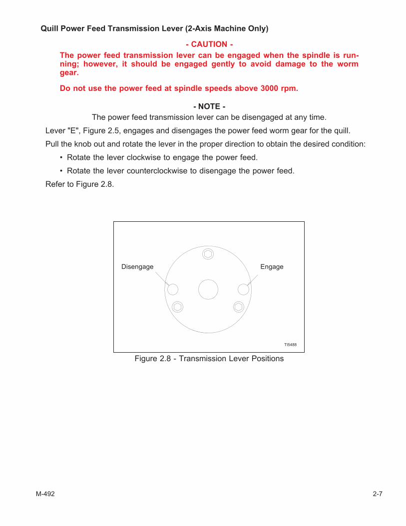
Quill Power Feed Transmission Lever (2-Axis Machine Only)
- CAUTION -
The power feed transmission lever can be engaged when the spindle is run-ning; however, it should be engaged gently to avoid damage to the wormgear.
Do not use the power feed at spindle speeds above 3000 rpm.
- NOTE -
The power feed transmission lever can be disengaged at any time.
Lever "E", Figure 2.5, engages and disengages the power feed worm gear for the quill.
Pull the knob out and rotate the lever in the proper direction to obtain the desired condition:
• Rotate the lever clockwise to engage the power feed.
• Rotate the lever counterclockwise to disengage the power feed.
Refer to Figure 2.8.
M-492 2-7
Figure 2.8 - Transmission Lever Positions
TI5488
Disengage Engage

Quill Feed Reverse Knob (2-Axis Machine Only)
The position of feed reverse knob "H", Figure 2.6, will determine the direction of quill motion whenthe quill feed control lever is engaged.
The direction of feed is also dependent on the direction of spindle motion. When using right-handcutting tools, the quill will travel:
• downward when the feed reverse knob is pressed inward
• upward when the feed reverse knob is pulled outward
The direction of travel will be reversed if the spindle is rotating in the appropriate direction forleft-hand cutting tools.
Quill Feed Control Lever (2-Axis Machine Only)
Feed control lever “I”, Figure 2.6, engages the overload clutch on the pinion shaft when positionedleft, and will stay engaged until either the quill comes in contact with the micrometer adjusting nut,forcing the feed control lever to drop out automatically, or released manually by moving the lever to theright.
Quill Feed Overload Clutch
- CAUTION -
Do not tamper with the power feed control overload clutch.
The power feed control overload clutch is factory set to hold up to 200 lbs down pressure on thequill. The feed control lever must be engaged in order to use power feed controls.
Quill Feed Selector (2-Axis Machine Only)
- NOTE -
It is easier to change the feedrate whenthe spindle is running.
Quill feed selector "K", Figure 2.9, is used to setthe feedrate when power feed is active. The availablefeedrates are:
.0015 inches / revolution
.003 inches / revolution
.006 inches / revolution
The feedrates are stamped next to the selectordetents.
Pull the knob outward and rotate the selector tothe desired setting.
2-8 M-492
Figure 2.9 - Quill Feed Selector
K
TP7253

Quill Micrometer Nut and Stop Knob (2-Axis Machine Only)
Micrometer nut "N", Figure 2.10, is used in conjunction with scale "M" for setting depth.
Rough position the micrometer nut by pressing button "O", sliding the micrometer nut to the approx-imate position.
Fine adjustment is achieved by rotating the micrometer nut. Each graduation on the nut equals .001inches of depth.
When the quill reaches the end of the intended travel during power feed, quill stop knob "L" contactsthe micrometer nut and automatically disengages quill feed control lever "I", Figure 2.6.
Quill Lock
Quill lock “G”, Figure 2.5, is a friction lock used when quill is in a stationary position, such as millingoperations. It is recommended that this lock be used whenever quill movement is not desired.
The quill lock is disengaged when the lever is in the upward position.
The quill lock is engaged when the lever is in the downward position.
M-492 2-9
Figure 2.10 - Quill Micrometer Nutand Stop Knob
TP7251
L
M
N
O

SPINDLE DRAW BAR
When tightening or loosening the draw bar "P", Figure 2.11, it is necessary to lock the spindle. Toaccomplish this, apply the spindle brake until it binds, then raise the Quill Feed handle to lock it inplace.
The draw bar has a 716 - 20 right hand thread and should be tightened with a normal amount of pres-
sure, using the wrench provided with the machine. Back off the draw bar to loosen the collet. If the col-let does not open immediately, lightly tap the knob on the top of the draw bar. The spindle has anon-sticking taper and the collet should release readily.
2-10 M-492
Figure 2.11 - Spindle Motor and Draw Bar
TP7248
P

HEAD ADJUSTMENTS
SWIVELING THE HEAD
- CAUTION -
Incorrect spline alignment can be caused by unequal tightening of the lock-ing nuts, causing fluctuation of the quill feed which can be felt through thefeed handle. Call your local Sales and Service Center before attempting thisprocedure.
- NOTE -
Swiveling the head is rotary motion of the head assembly as viewed from above themachine.
The top of the machine head can be swivelled byloosening the 3 locking nuts “A” Figure 2.12.
- WARNING -
To prevent personal injury or dam-age to machine, DO NOT remove thethree locking nuts after loosening.
1. Loosen the 3 locking nuts, BUT DO NOTREMOVE.
2. Swivel the head to the required position.
3. Tighten the 3 locking nuts snugly before finaltightening. Run the spindle to obtain correctspine alignment, then re-tighten locking nutssecurely.
TILTING THE HEAD
- NOTE -
Tilting the head is rotary motion of thehead assembly as viewed from eitherside of the machine.
1. Use the wrench provided with the machine toloosen 3 bolts “C”, Figure 2.13.
2. Turn bolt “B” to tilt the head as needed.
3. Tighten 3 bolts “C”.
M-492 2-11
Figure 2.12 - Swivel Head Locking Nuts
A
TP5370
Figure 2.13 - Head Tilt Bolts
B
C
TP5375

ROTATING THE HEAD
- NOTE -
Rotating the head is rotary motion ofthe head assembly as viewed from thefront of the machine.
1. Use the wrench provided with the machine toloosen 4 nuts “D”, Figure 2.14.
- NOTE -
The head is capable of rotating 25° ineither direction without releasing stoppin “E”, Figure 2.15. Pull stop pin “E”out to allow the head to be rotated fur-ther than 25°.
2. Turn bolt “F”, Figure 2.16, to rotate the head asneeded.
3. Tighten 4 nuts “D”, Figure 2.14.
2-12 M-492
Figure 2.14 - Head Rotation Locking Nuts
TP5372
D
Figure 2.15 - Head Rotation Stop Pin
TP5376
E
Figure 2.16 - Head Rotating Bolt
TP5369
F

TURRET ADJUSTMENT
- NOTE -
Swiveling the turret is rotary motion of the turret as viewed from above the machine.
- WARNING -
DO NOT remove the bolts from the turret.
1. Use the wrench provided with the machine to loosen 4 bolts “G”, Figures 2.17 and 2.18.
2. Manually swivel the turret to the required position.
3. Torque the 4 bolts to 47 lb-ft.
RAM ADJUSTMENT
- NOTE -
It is recommended that on heavy milling work the head should be kept as close tothe column as possible, where maximum rigidity is obtained.
The ram portion of the machine can be slid front to back.
1. Use the wrench provided and loosen bolts “I”, Figure 2.18.
2. Use wrench to move the slide to the desired position using bolt “H”.
3. Re-tighten bolts “I” starting with the rear bolt.
M-492 2-13
Figure 2.17 - Turret and Ram(Left Side)
G
TP5374
Figure 2.18 - Turret and Ram(Right Side)
G
H
I
TP5373

SADDLE CLAMPING
- NOTE -
The saddle clamp should not be used when power to the axis drives is ON.
The saddle clamp is located at “J”, Figure 2.19. When milling with longitudinal table feed only, it isadvisable to clamp the knee to the column and the saddle to the knee to add rigidity to these membersand provide for heavier cuts with minimum vibration.
Excessive pressure can cause slight table bind. Use moderate clamping pressure, as this will holdthe saddle sufficiently.
TABLE CLAMPING
- NOTE -
The table clamps should not be used when power to the axis drives is ON.
The table clamps are located at “K”, Figure 2.19. Table clamp levers should always be clampedwhen longitudinal movement is not required.
KNEE CLAMPING
The knee clamp is located at “L”, Figure 2.20. Leave clamped at all times unless raising or loweringthe knee using the Knee Crank handle.
2-14 M-492
Figure 2.19 - Saddle Clampand Table Clamps
JK
TP5358
Figure 2.20 - Knee Clamp
L
TP5357

- NOTES -
M-492 2-15

- NOTES -
2-16 M-492

CHAPTER 3 - MAINTENANCE
HEAD
MOTOR REMOVAL
1. Run head to adjust to lowest speed.
2. Disconnect power.
3. Remove three screws “A” and cover “B”, Fig-ure 3.1.
4. Using the two screws “A”, compress spring“C”.
5. Rotate the speed changer to the highestspeed.
6. Remove the reversing switch from the belthousing.
7. Remove the two securing screws “D”.
8. Lift the motor and rest the case on stud “E”,Figure 3.2.
9. Ease the belt over the lower drive disc andremove the motor.
M-492 3-1
Figure 3.1 - Motor RemovalFront View
D
TP5320
C
AB
Figure 3.2 - Motor RemovalSide View
TP5321
E

DRIVE BELT REPLACEMENT
1. Remove the motor as described on Page3-1.
2. Remove the three screws “F”, Figure 3.3,insert into the adjacent tapped holes andwithdraw bearing housing “G”.
3. Remove the two screws and the bushings“H”.
4. Remove four screws “I” and one screw“J”.
5. Remove four screws securing speedchanger “K”.
6. Remove top housing “L”. Tap to clear thedowels.
7. Replace the belt.
TIMING BELT REPLACEMENT
1. Remove the motor.
2. Lower the quill to full extent.
3. Remove two lower cap screws “M”, Fig-ure 3.4, from the speed changer housing.
4. Remove four cap screws “N”.
5. Remove top assembly “O”, and tap toclear dowels
6. Replace the belt.
3-2 M-492
Figure 3.3 - Drive Belt Replacement
TP5322
F
G
I
K
HL
J
Figure 3.4 - Timing Belt Replacement
N
TP5323
MO

BRAKE SHOE REPLACEMENT
1. Remove the top section.
2. Remove the two screws “P”, Figure 3.5.
3. Remove the clutch hub assembly “Q”.
4. Replace the brake shoes “R”.
5. Remove the bearing, drive discs andcirclips from the hub assembly “Q”.
6. Replace the bearing and housing “S”.
7. Thread hub “B” through the bearing andreassemble the discs, etc.
M-492 3-3
Figure 3.5 - Brake Shoe Replacement
TP5324
Q
S
R
P

Z AXIS AND SPINDLE
MICRO FEED TRIP ASSEMBLY AND QUILL REMOVAL
1. Remove screw “A” and ball reverse lever“B”, Figure 3.6.
2. Remove retaining ring “C”, screw “D” andarm “E”.
3. Thread shaft “F” through micro nuts and re-move.
4. Remove screw “G” and stop “H”.
5. Remove quill.
6. Clean all areas, oil liberally and reassem-ble.
7. Check correct operation of micro feed tripassembly together with feed trip linkage asper feed tripping adjustment (see Figure3.8).
3-4 M-492
Figure 3.6 - Micro Feed Trip Assembly andQuill Removal
TP5325
G
H
B
A
F
C
E
D
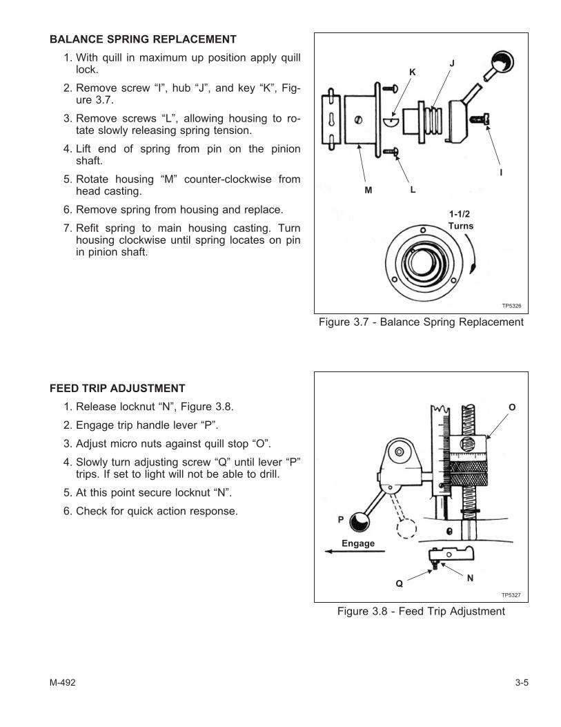
BALANCE SPRING REPLACEMENT
1. With quill in maximum up position apply quilllock.
2. Remove screw “I”, hub “J”, and key “K”, Fig-ure 3.7.
3. Remove screws “L”, allowing housing to ro-tate slowly releasing spring tension.
4. Lift end of spring from pin on the pinionshaft.
5. Rotate housing “M” counter-clockwise fromhead casting.
6. Remove spring from housing and replace.
7. Refit spring to main housing casting. Turnhousing clockwise until spring locates on pinin pinion shaft.
FEED TRIP ADJUSTMENT
1. Release locknut “N”, Figure 3.8.
2. Engage trip handle lever “P”.
3. Adjust micro nuts against quill stop “O”.
4. Slowly turn adjusting screw “Q” until lever “P”trips. If set to light will not be able to drill.
5. At this point secure locknut “N”.
6. Check for quick action response.
M-492 3-5
Figure 3.7 - Balance Spring Replacement
J
I
K
M
TP5326
1-1/2
Turns
L
Figure 3.8 - Feed Trip Adjustment
Engage
O
P
NQ
TP5327

COLLET ALIGNING SCREW REPLACEMENT
1. Use felt pen, mark reference line on quilland nose cap “S”, Figure 3.9.
2. Remove set screw “R”.
3. Unscrew nose cap “S”.
4. Remove lock screw “T” and collet aligningscrew “U”.
5. Replace “U”; insert collet and check thatthe dog on the end of the screw does notinterfere with the bottom of the guide slot.
6. Replace lock screw “T”.
7. Replace nose cap “S”; check felt penmarkings for correct alignment.
8. Replace set screw “R”. CAUTION - DONO OVERTIGHTEN as this will causedistortion.
9. Check gap “V” (.003”, .08mm)
- CAUTION -
Do not attempt to remove nosecap before removing set screw“R”. Doing so will cause seriousdamage.
3-6 M-492
Figure 3.9 - Collet Aligning ScrewReplacement
TP5328
UT
R
S
U
T
V

TABLE GIB ADJUSTMENT
The table gib is used for adjusting the table bearing on the saddle. The gib serves as a guide for thetable travel.
1. Clean the front angular face of the saddle.
- NOTE -
Figure 3.10 shows how the left side indicatoris mounted. Mount the right side indicatorfacing toward the right end of the machine inthe same manner. Refer also to Figure 3.11.
2. Mount two magnetic-based indicators on thefront angular face of the saddle.
3. Push the right end of the table by applying 50lbf [222 N] and pull the left end of the table byapplying 50 lbf [222 N], as shown in Figure3.11.
4. Zero the indicators.
M-492 3-7
Figure 3.10 - Left Indicator Positionfor the Table Gib Adjustment
TP6995
Figure 3.11 - Indicator Positions for Table Gib Adjustment
TP6998
Direction of ForceApplied to the Table
Table
Right Side IndicatorLeft Side Indicator
12[304.8]
12[304.8]
NOTE:Dimensions shown in inches [millimeters].
Saddle
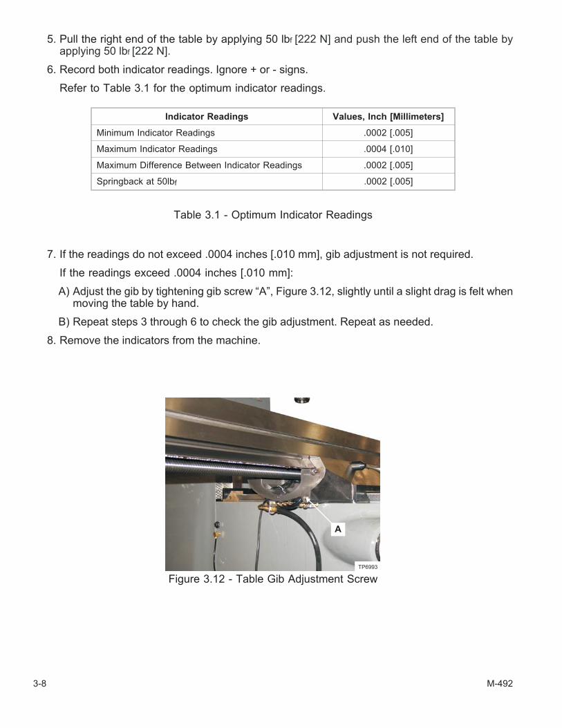
5. Pull the right end of the table by applying 50 lbf [222 N] and push the left end of the table byapplying 50 lbf [222 N].
6. Record both indicator readings. Ignore + or - signs.
Refer to Table 3.1 for the optimum indicator readings.
7. If the readings do not exceed .0004 inches [.010 mm], gib adjustment is not required.
If the readings exceed .0004 inches [.010 mm]:
A) Adjust the gib by tightening gib screw “A”, Figure 3.12, slightly until a slight drag is felt whenmoving the table by hand.
B) Repeat steps 3 through 6 to check the gib adjustment. Repeat as needed.
8. Remove the indicators from the machine.
3-8 M-492
Indicator Readings Values, Inch [Millimeters]
Minimum Indicator Readings .0002 [.005]
Maximum Indicator Readings .0004 [.010]
Maximum Difference Between Indicator Readings .0002 [.005]
Springback at 50lbf .0002 [.005]
Table 3.1 - Optimum Indicator Readings
Figure 3.12 - Table Gib Adjustment Screw
TP6993
A

SADDLE GIB ADJUSTMENT
The saddle gib is used for adjusting the saddle bearing on the knee. The gib serves as a guide forthe saddle travel.
- NOTE -
Observe the orientation of the front saddle wiper before removing.
1. Remove three screws and slide front saddle wiper “B”, Figure 3.13, off the machine.
2. Move the Y axis to position the saddle at the approximately midpoint of travel.
- NOTE -
Figure 3.14 shows how the front indicator is mounted. Mount the rear indicator fac-ing toward the front of the machine in the same manner. Refer also to Figure 3.15.
3. Clean the dovetail surfaces to be used to mount the magnetic-based indicators.
4. Mount two magnetic-based indicators on the left dovetail surface on the top of the knee.
5. Push the right end of the table by applying 50 lbf [222 N] and pull the left end of the table byapplying 50 lbf [222 N], as shown in Figure 3.15.
6. Zero the indicators.
7. Pull the right end of the table by applying 50 lbf [222 N] and push the left end of the table byapplying 50 lbf [222 N].
8. Record both indicator readings. Ignore + or - signs.
Refer to Table 3.1 for the optimum indicator readings.
M-492 3-9
Figure 3.13 - Front Wiper on Saddle
TP6991
B
Figure 3.14 - Front Indicator Positionfor Saddle Gib Adjustment
TP6994
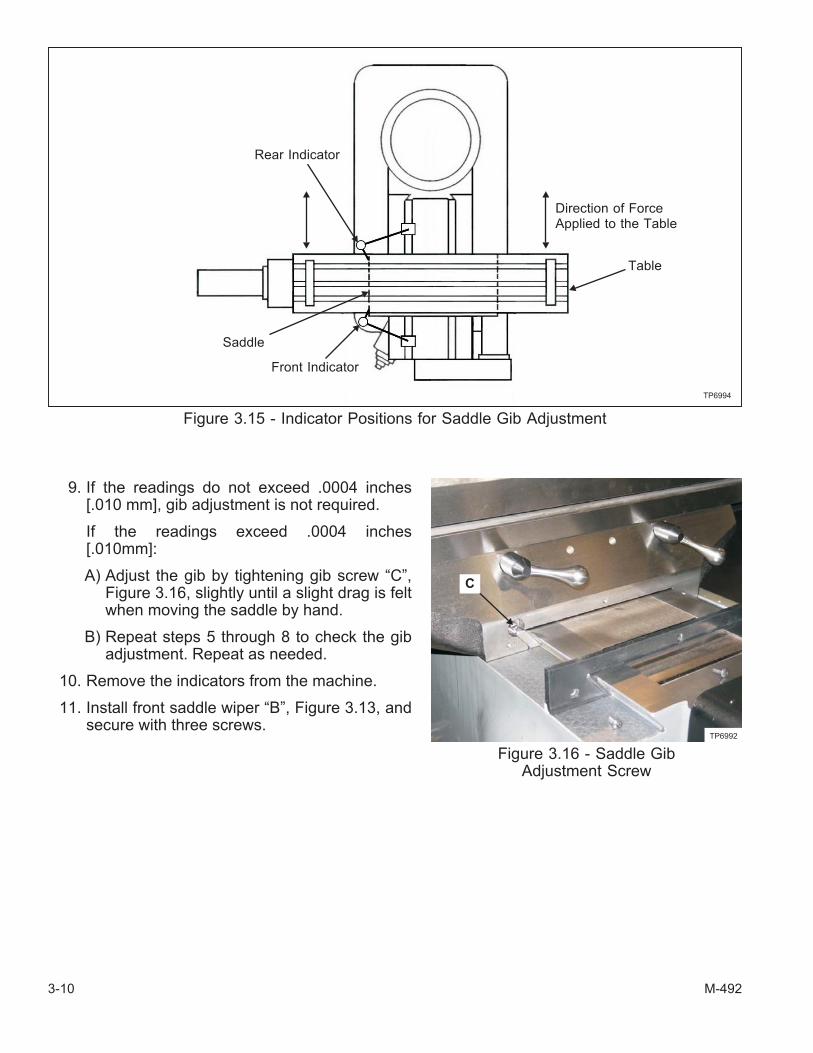
9. If the readings do not exceed .0004 inches[.010 mm], gib adjustment is not required.
If the readings exceed .0004 inches[.010mm]:
A) Adjust the gib by tightening gib screw “C”,Figure 3.16, slightly until a slight drag is feltwhen moving the saddle by hand.
B) Repeat steps 5 through 8 to check the gibadjustment. Repeat as needed.
10. Remove the indicators from the machine.
11. Install front saddle wiper “B”, Figure 3.13, andsecure with three screws.
3-10 M-492
Figure 3.15 - Indicator Positions for Saddle Gib Adjustment
TP6994
Direction of ForceApplied to the Table
Front Indicator
Rear Indicator
Saddle
Table
Figure 3.16 - Saddle GibAdjustment Screw
TP6992
C

KNEE GIB ADJUSTMENT
1. Move the X axis to position the table at the approximate midpoint of travel.
2. Move the Y axis to position rear saddle surface “D”, Figure 3.17, approximately four inches [100millimeters] from column dovetail surface “E”, Figure 3.18.
3. Loosen the jam nuts on gib adjustment screws “F”, Figure 3.19.
4. Use a hex wrench to loosen the gib adjustment screws approximately ¼ turn.
5. Alternately and evenly, torque the gib adjustment screws to 40 lb-in [4.5 N•m].
- NOTE -
DO NOT allow the gib adjustment screws to turn while tightening the jam nuts.
6. Hold the gib adjustment screws in place with the hex wrench while tightening the jam nuts.
M-492 3-11
Figure 3.17 - Rear View of the Saddle
D
TP7000
Figure 3.18 - Vertical Dovetailon the Column
E
TP7001
Figure 3.19 - Knee Gib Adjustment Screws
F
TP5382

- NOTES -
3-12 M-492

CHAPTER 4 - PARTS LISTINGS
2J-HEAD TOP HOUSING
M-492 4-1
Figure 4.1 - 2J-Head Assembly
TP5340
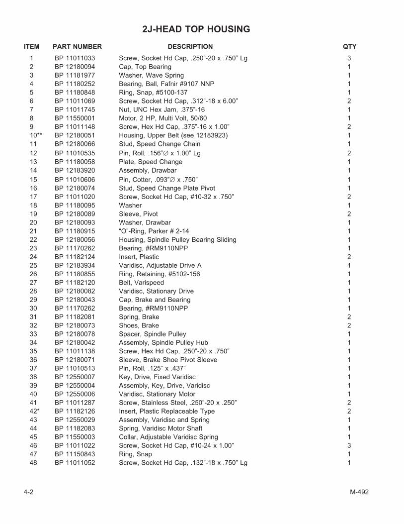
2J-HEAD TOP HOUSING
ITEM PART NUMBER DESCRIPTION QTY
1 BP 11011033 Screw, Socket Hd Cap, .250”-20 x .750” Lg 3
2 BP 12180094 Cap, Top Bearing 1
3 BP 11181977 Washer, Wave Spring 1
4 BP 11180252 Bearing, Ball, Fafnir #9107 NNP 1
5 BP 11180848 Ring, Snap, #5100-137 1
6 BP 11011069 Screw, Socket Hd Cap, .312”-18 x 6.00” 2
7 BP 11011745 Nut, UNC Hex Jam, .375”-16 1
8 BP 11550001 Motor, 2 HP, Multi Volt, 50/60 1
9 BP 11011148 Screw, Hex Hd Cap, .375”-16 x 1.00” 2
10** BP 12180051 Housing, Upper Belt (see 12183923) 1
11 BP 12180066 Stud, Speed Change Chain 1
12 BP 11010535 Pin, Roll, .156”� x 1.00” Lg 2
13 BP 11180058 Plate, Speed Change 1
14 BP 12183920 Assembly, Drawbar 1
15 BP 11010606 Pin, Cotter, .093”� x .750” 1
16 BP 12180074 Stud, Speed Change Plate Pivot 1
17 BP 11011020 Screw, Socket Hd Cap, #10-32 x .750” 2
18 BP 11180095 Washer 1
19 BP 12180089 Sleeve, Pivot 2
20 BP 12180093 Washer, Drawbar 1
21 BP 11180915 “O”-Ring, Parker # 2-14 1
22 BP 12180056 Housing, Spindle Pulley Bearing Sliding 1
23 BP 11170262 Bearing, #RM9110NPP 1
24 BP 11182124 Insert, Plastic 2
25 BP 12183934 Varidisc, Adjustable Drive A 1
26 BP 11180855 Ring, Retaining, #5102-156 1
27 BP 11182120 Belt, Varispeed 1
28 BP 12180082 Varidisc, Stationary Drive 1
29 BP 12180043 Cap, Brake and Bearing 1
30 BP 11170262 Bearing, #RM9110NPP 1
31 BP 11182081 Spring, Brake 2
32 BP 12180073 Shoes, Brake 2
33 BP 12180078 Spacer, Spindle Pulley 1
34 BP 12180042 Assembly, Spindle Pulley Hub 1
35 BP 11011138 Screw, Hex Hd Cap, .250”-20 x .750” 1
36 BP 12180071 Sleeve, Brake Shoe Pivot Sleeve 1
37 BP 11010513 Pin, Roll, .125” x .437” 1
38 BP 12550007 Key, Drive, Fixed Varidisc 1
39 BP 12550004 Assembly, Key, Drive, Varidisc 1
40 BP 12550006 Varidisc, Stationary Motor 1
41 BP 11011287 Screw, Stainless Steel, .250”-20 x .250” 2
42* BP 11182126 Insert, Plastic Replaceable Type 2
43 BP 12550029 Assembly, Varidisc and Spring 1
44 BP 11182083 Spring, Varidisc Motor Shaft 1
45 BP 11550003 Collar, Adjustable Varidisc Spring 1
46 BP 11011022 Screw, Socket Hd Cap, #10-24 x 1.00” 3
47 BP 11150843 Ring, Snap 1
48 BP 11011052 Screw, Socket Hd Cap, .132”-18 x .750” Lg 1
4-2 M-492

ITEM PART NUMBER DESCRIPTION QTY
49 BP 11182122 Key, Plastic 1
50 BP 11011707 Nut, Hex Jam, .250”-20 1
51 BP 12180084 Key 1
52 BP 12180107 Pin, Taper, #4 x 1.00” 4
53** BP 12180052 Base, Belt Housing (see 12183923) 1
54 BP 12180088 Cover, Motor Pulley 1
56 BP 11011552 Screw, Drive, Type U, #0 x .250” 4
58 BP 11182893 Nameplate, Hi-Low Range 1
61 BP 11182894 Nameplate, Quill Feed 1
63 BP 12180053 Housing, Gear 1
64 BP 11011443 Screw, Round Hd Machine, #10-24 x .375” 3
65 BP 11185030 Plate, Gear Housing 1
66 BP 11180818 Ring, Snap, #5100-25 1
67 BP 11182306 Finger, Brake Operating 2
68 BP 12180083 Stud, Brake Finger Pivot 1
69 BP 11192151 Knob, Bakelite, .250”-20 1
70 BP 12190133 Handle, Brake 1
71 BP 12190134 Pin, Brake Lock 1
72 BP 11011260 Screw, Stainless Steel, #10-32 UNF x .250” 1
73 BP 12180104 Sleeve, Brake Lock Shaft 1
74 BP 28025521 Shaft, Brake Lock 1
75 BP 12180069 Cam, Brake Lock 1
78 BP 11011031 Screw, Socket Hd Cap, .250”-20 x .625” 1
80 BP 11011019 Screw, Flat Hd Cap, #10-32 x .500” 1
82 BP 11011006 Screw, Socket Hd Cap, #8-32 x .250” 1
83 BP 12550008 Key 1
* Non-replaceable turcite bushing must be purchased as part of varidisc assembly #12550029.
**Items 10 and 53 sold as assembly only.
M-492 4-3

2J-HEAD BACK GEAR
4-4 M-492
Figure 4.2 - 2J-Head Back Gear Assembly
TP5341

2J-HEAD BACK GEAR
ITEM PART NUMBER DESCRIPTION QTY
1 BP 11011710 Nut, Hex, .312” 1
2 BP 11180133 Dial, Spindle Speed 1
3 BP 11183646 Bushing, Bronze, .502” x .628” x 5.00” 1
4 BP 11011380 Screw, Full Dog Socket Hd Set, .250”-20 x .500” 1
5 BP 12180055 Housing, Speed Changer 1
6 BP 12182003 Block, Plastic Bearing 1
7 BP 11011031 Screw, Socket Hd Cap, .250”-20 x .625” 4
8 BP 11010516 Pin, Roll, .125” x .625” Lg 1
9 BP 11010520 Pin, Roll, .125”� x 1.00” Lg 1
10 BP 11183720 Chain, Speed Changer, Morse #35 1
11 BP 12180066 Stud, Speed Change Chain 1
12 BP 12180051 Housing, Belt (see 12183923) 1
13 BP 12180094 Cap, Top Bearing 1
14 BP 11011065 Screw, Socket Hd Cap, .312”-18 x 4.00” 1
17 BP 12182001 Hub, Speed Change 1
18 BP 11181233 Screw, Socket Hd Set, .250”-UNC x .375” 2
19 BP 11182178 Handle, Machine, #3302 1
20 BP 11182892 Plate, Caution 1
24 BP 11011287 Screw, Stainless Steel, .250”-20 x .250” 2
25 BP 11011037 Screw, Socket Hd Cap, .250”-20 x 1.250” 4
27 BP 11183645 Bushing, Oilite 1
28 BP 28300619 Pin, Roll, 2.5mm x 12mm Lg 1
29 BP 28025716 Shaft, Speed Changer 1
30 BP 28007307 Gear, Boston Worm 1
31 BP 11180214 Bushing, Oilite Flanged, FB 1
32 BP 11010539 Pin, Roll, .187”� x .375” Lg 1
33 BP 12180090 Gear, Speed Changer Spur 1
34 BP 11181923 Washer, Wavy Spring 1
35 BP 12180065 Drum, Speed Change Chain 1
36 BP 11552106 Belt, Timing 1
37* BP 12180042 Hub, Spindle Pulley 1
38* BP 12180064 Sleeve, Timing Pulley Clutch 1
39 BP 12180059 Hub, Splined Gear 1
40** BP 12180062 Gear, Spindle Bull (see 12183933) 1
41 BP 11180254 Bearing, Ball, Fafnir #RM9308NPP 2
42 BP 11180803 Ring, Snap, #5000-244 2
43 BP 12180063 Spacer, Bull Gear Bearing 1
44 BP 12180053 Housing, Gear 1
45 BP 11181650 Bolt, Tee 3
46 BP 11181906 Washer, Flat, .469” ID x .938” OD x .063” 3
47 BP 11011750 Nut, HDN Finished Hex Jam, .438”-14 3
48 BP 11181986 Washer, Ball Bearing Gear Sleeve 3
49*** BP 12183924 Bracket, Fixed Clutch 1
50 BP 11011246 Screw, Socket Hd Set, .312”-18 x .312” 2
51 BP 28025615 Guide 2
52 BP 28025671 Screw, Flat Socket Hd Cap, #10-32 x .375” 2
53 BP 11010511 Pin, Roll, .125” x .250” Lg 1
54 BP 11183104 Cup, Oil, Gits #1202 Style L 1
M-492 4-5

ITEM PART NUMBER DESCRIPTION QTY
55 BP 11182071 Spring, Compression, .375” OD x .3.00” Lg 3
56 BP 11181794 Locknut, Bearing, #–08 1
57*** BP 12183924 Sleeve, Bearing 1
58 BP 11181977 Washer, Wave Spring 1
59 BP 12180067 Pinion, Bull Gear Shift 1
60 BP 12180161 Plate, Hi-Low Detent 1
61 BP 11181732 Nut, Hex, .375”-16 3
62 BP 11151913 Lockwasher, .375” 3
63 BP 12180085 Stud 3
66 BP 12180100 Plunger, Hi-Low Detent 1
67 BP 11182072 Spring, .750” x .032 x .563” 1
68 BP 11011017 Screw, Socket Hd Cap, #10-32 x .500” Lg 2
69 BP 11192151 Knob, Bakelite, .250”-20 1
70 BP 12180099 Crank, Hi-Low Shift 1
71 BP 12180096 Block, Hi-Low Pinion 1
72 BP 11010516 Pin, Roll, .125” x .625” Lg 1
73 BP 11011052 Screw, Socket Hd Cap, .132”-18 x .750” Lg 4
74 BP 11181007 Screw, Socket Hd Cap, #8-32 x .625” 2
75 BP 11011022 Screw, Socket Hd Cap, #10-24 x 1.00” 1
76 BP 12180088 Cover, Motor Pulley 1
78 BP 11013079 Key, Woodruff #9 2
79 BP 11180235 Bearing, #203NPP-C8 2
80 BP 12180075 Shaft, Bull Gear Pinion Counter 1
81 BP 12180103 Key, Sq, .312” x .540” 1
82 BP 11181975 Washer, Wave Spring 1
83** BP 12180077 Pinion, Bull Gear (see 12183933) 1
84 BP 12180076 Cap, Bull Gear Pinion Bearing 1
85 BP 11011011 Screw, Socket Hd Cap, #10-24 x .625” Lg 2
86 BP 12550016 Pulley, Timing Belt 1
87 BP 11191738 Nut, Hex Jam, .625”-18 1
88 BP 11182912 Nameplate, Speed Change 1
89 BP 11011139 Screw, Flat Hd Machine, #8-32 x .750” 2
90 BP 11182897 Plate, Lubrication 1
93 BP 11598117 Assembly, Reversing Switch 1
*Items 37 and 38 sold as assembly only.
**Items 40 and 83 sold as assembly only.
***Items 49 and 57 sold as assembly only.
4-6 M-492
2J-HEAD LOWER HOUSING
M-492 4-7
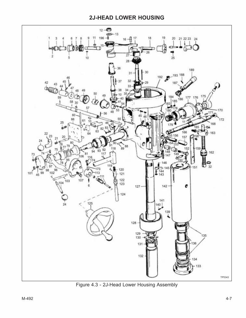
Figure 4.3 - 2J-Head Lower Housing Assembly
TP5343
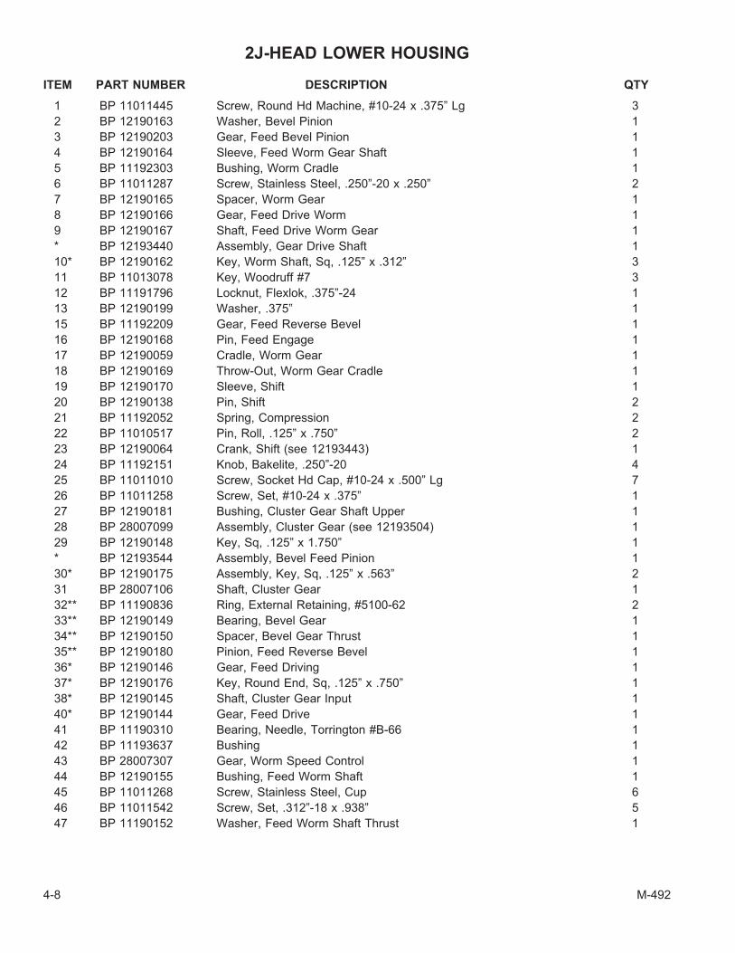
2J-HEAD LOWER HOUSING
ITEM PART NUMBER DESCRIPTION QTY
1 BP 11011445 Screw, Round Hd Machine, #10-24 x .375” Lg 3
2 BP 12190163 Washer, Bevel Pinion 1
3 BP 12190203 Gear, Feed Bevel Pinion 1
4 BP 12190164 Sleeve, Feed Worm Gear Shaft 1
5 BP 11192303 Bushing, Worm Cradle 1
6 BP 11011287 Screw, Stainless Steel, .250”-20 x .250” 2
7 BP 12190165 Spacer, Worm Gear 1
8 BP 12190166 Gear, Feed Drive Worm 1
9 BP 12190167 Shaft, Feed Drive Worm Gear 1
* BP 12193440 Assembly, Gear Drive Shaft 1
10* BP 12190162 Key, Worm Shaft, Sq, .125” x .312” 3
11 BP 11013078 Key, Woodruff #7 3
12 BP 11191796 Locknut, Flexlok, .375”-24 1
13 BP 12190199 Washer, .375” 1
15 BP 11192209 Gear, Feed Reverse Bevel 1
16 BP 12190168 Pin, Feed Engage 1
17 BP 12190059 Cradle, Worm Gear 1
18 BP 12190169 Throw-Out, Worm Gear Cradle 1
19 BP 12190170 Sleeve, Shift 1
20 BP 12190138 Pin, Shift 2
21 BP 11192052 Spring, Compression 2
22 BP 11010517 Pin, Roll, .125” x .750” 2
23 BP 12190064 Crank, Shift (see 12193443) 1
24 BP 11192151 Knob, Bakelite, .250”-20 4
25 BP 11011010 Screw, Socket Hd Cap, #10-24 x .500” Lg 7
26 BP 11011258 Screw, Set, #10-24 x .375” 1
27 BP 12190181 Bushing, Cluster Gear Shaft Upper 1
28 BP 28007099 Assembly, Cluster Gear (see 12193504) 1
29 BP 12190148 Key, Sq, .125” x 1.750” 1
* BP 12193544 Assembly, Bevel Feed Pinion 1
30* BP 12190175 Assembly, Key, Sq, .125” x .563” 2
31 BP 28007106 Shaft, Cluster Gear 1
32** BP 11190836 Ring, External Retaining, #5100-62 2
33** BP 12190149 Bearing, Bevel Gear 1
34** BP 12190150 Spacer, Bevel Gear Thrust 1
35** BP 12190180 Pinion, Feed Reverse Bevel 1
36* BP 12190146 Gear, Feed Driving 1
37* BP 12190176 Key, Round End, Sq, .125” x .750” 1
38* BP 12190145 Shaft, Cluster Gear Input 1
40* BP 12190144 Gear, Feed Drive 1
41 BP 11190310 Bearing, Needle, Torrington #B-66 1
42 BP 11193637 Bushing 1
43 BP 28007307 Gear, Worm Speed Control 1
44 BP 12190155 Bushing, Feed Worm Shaft 1
45 BP 11011268 Screw, Stainless Steel, Cup 6
46 BP 11011542 Screw, Set, .312”-18 x .938” 5
47 BP 11190152 Washer, Feed Worm Shaft Thrust 1
4-8 M-492

ITEM PART NUMBER DESCRIPTION QTY
* BP 12193435 Assembly, Bevel Feed Gear 1
48* BP 11183646 Bushing, Bronze, .502” x .628” x 5.00” 2
49* BP 12190151 Gear, Feed Reverse Bevel 2
50 BP 12190153 Clutch, Feed Reverse 1
53 BP 11011547 Lock, Screw, Stainless Steel, .312”-18 x .156” 1
54 BP 11011375 Screw, Stainless Steel, .312”-18 x .312” 1
55 BP 12190157 Rod, Reverse Clutch 1
56 BP 11010509 Pin, Roll, .093” x .750” 1
57 BP 12190198 Shaft, Feed Worm 1
58 BP 12190200 Pin, .093” x .312” Lg 1
59 BP 28007308 Pin, .100 x .438” Lg 1
60 BP 12190179 Rod, Feed Shift 1
61 BP 11011260 Screw, Stainless Steel, #10-32 UNF x .250” 1
63 BP 11190061 Fork, Feed Gear Shift 1
64 BP 12193446 Assembly, Cluster Gear Shift Crank 1
66 BP 12190065 Cover, Cluster Gear 1
73 BP 11011014 Screw, Cap, #10-24 x 1.500” Lg 2
74 BP 12190188 Pin, Stop 2
75 BP 12190098 Ring, Clutch 1
76 BP 11011265 Screw, Stainless Steel, .250”-20 x .250” Lg 1
77 BP 12190073 Plug, Brass, .187”� x .093” 1
78 BP 12190105 Locknut, Overload Clutch 1
79 BP 11192055 Spring, Safety Clutch 1
80 BP 11192302 Clutch, Overload 1
81 BP 12193549 Sleeve, Overload Clutch 1
82 BP 11191920 Washer, Single Spring 3
83 BP 11011431 Screw, Round Hd Machine, #8-32 x .625” 3
88 BP 11192032 Spring, Compression, .250”� x 1.250” 1
89 BP 12190096 Plunger, Overload Clutch Lever Spring 1
90 BP 12190106 Bushing, Quill Pinion Shaft 1
91 BP 12190104 Spacer, Pinion Shaft Worm Gear 1
92 BP 11190103 Gear, Overload Clutch Worm 1
93 BP 12190102 Ring, Overload Clutch 1
94 BP 11190870 Ring, External Retaining 1
95 BP 11010717 Pin, Dowel, .187” x .750” 1
96 BP 12193427 Assembly, Overload Clutch Trip Lever 1
97 BP 12190097 Washer, Overload Clutch 1
98 BP 11190822 Ring, External Retaining, #5100-37 1
99 BP 12190068 Cover, Clutch Arm 1
101 BP 11011740 Nut, Hex Jam, .250”-20 1
102 BP 11010717 Pin, Dowel, .187” x .750” 1
103 BP 12190094 Rod, Cam 1
104 BP 12190095 Handle, Trip 1
106 BP 12190067 Bracket, Feed Trip 1
107 BP 11011035 Screw, Socket Hd Cap, .250”-20 x 1.00” 1
111 BP 12193433 Assembly, Reverse Knob 2
113 BP 12190159 Assembly, Handwheel Clutch (see 12193519) 1
116 BP 12190154 Assembly, Handwheel Clutch Spring 1
117 BP 11010515 Pin, Roll, .125” x .562” 1
118 BP 12190093 Assembly, Cam Rod Sleeve 1
M-492 4-9

ITEM PART NUMBER DESCRIPTION QTY
119 BP 11010513 Pin, Roll, .125” x .437” 1
120 BP 11192053 Spring, Compression 1
121 BP 12190091 Plunger, Trip 1
122 BP 12190092 Bushing, Feed Trip Plunger 1
123 BP 12190090 Bushing, Trip Plunger 1
125 BP 12190089 Plunger, Feed Trip 1
125 BP 12193519 Assembly, Handwheel 1
127 BP 12190191 Spindle 1
128 BP 11190081 Skirt, Quill 1
129 BP 11191790 Locknut, #06 1
130 BP 11191942 Lockwasher, #W-06 1
131 BP 11190237 Bearing, Spindle 1
132 BP 12190197 Sleeve, Bearing 1
133 BP 12190196 Nosepiece 1
134 BP 12780915 Shield, Spindle Dirt 1
135 BP 11190238 Bearing, Spindle, Set 1
136 BP 12193513 Bearing, Spindle, Set 1
139 BP 11011265 Screw, Stainless Steel, .250”-20 x .250” Lg 1
140 BP 12193540 Screw, Set, R-8 Collet 1
141 BP 11011545 Screw, Locking Set, .250”-32 x .125” 1
142* BP 12190192 Quill (See 12194541) 1
143 BP 28300336 Nut, Steel, #6-32 NC 1
144 BP 28300609 Screw, Stainless Steel, #6-32 x .750” 1
145 BP 28007042 Lever, Feed Trip (see 12193498) 1
146 BP 12190185 Pin, Trip Lever 1
147 BP 12200103 Rod, Indicator 1
148 BP 12190109 Sleeve, Quill Lock, Tapped 1
149 BP 12200098 Handle, Lock 2
150 BP 11011595 Screw, Washer Hd Machine, #10-32 x .375” 1
151 BP 11192403 Strainer, Felt 1
152 BP 12190111 Bolt, Quill Lock 1
153 BP 12190110 Sleeve, Quill Lock, Untapped 1
154 BP 12200102 Screw, Rod Indicator Thumb 4
155 BP 12191620 Bolt, Tee, .500” 2
156 BP 12190135 Spacer, Lower Clamping Bolt 2
157 BP 12191736 Nut, Hex, .500” x 1.500” 2
158 BP 11011411 Screw, Chem Black Round Hd Machine, #6-32 x .250” 1
159 BP 11195306 Scale, Quill Micrometer Inch 1
162 BP 12190344 Assembly, Quick Nut 1
163 BP 12190082 Nut, Quill Stop 1
164 BP 12190083 Screw, Quill Stop Micro 1
165 BP 11011090 Screw, Socket Hd Cap, .375”-24 x .625” Lg 1
166 BP 28007063 Shaft, Quill Pinion 1
168 BP 12200111 Pin, Spring 1
170 BP 11010541 Pin, Roll, .187” x .750” Lg 1
171 BP 11013076 Key, Woodruff #3 1
172 BP 12190182 Screw, Pinion Shaft Hub 1
173 BP 11192165 Ball, Steel 1
174 BP 11192054 Spring, Compression 1
175 BP 12201033 Assembly, Quill Feed Handle 1
4-10 M-492
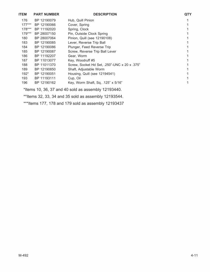
ITEM PART NUMBER DESCRIPTION QTY
176 BP 12190079 Hub, Quill Pinion 1
177*** BP 12190066 Cover, Spring 1
178*** BP 11192020 Spring, Clock 1
179*** BP 28007150 Pin, Outside Clock Spring 1
180 BP 28007064 Pinion, Quill (see 12190108) 1
183 BP 12190085 Lever, Reverse Trip Ball 1
184 BP 12190086 Plunger, Feed Reverse Trip 1
185 BP 12190087 Screw, Reverse Trip Ball Lever 1
186 BP 11192207 Gear, Worm 1
187 BP 11013077 Key, Woodruff #5 1
188 BP 11011370 Screw, Socket Hd Set, .250”-UNC x 20 x .375” 1
189 BP 12190850 Shaft, Adjustable Worm 1
192* BP 12190051 Housing, Quill (see 12194541) 1
193 BP 11193111 Cup, Oil 1
196 BP 12190162 Key, Worm Shaft, Sq, .125” x 5/16” 1
*Items 10, 36, 37 and 40 sold as assembly 12193440.
**Items 32, 33, 34 and 35 sold as assembly 12193544.
***Items 177, 178 and 179 sold as assembly 12193437
M-492 4-11

BASIC MACHINE
4-12 M-492
Figure 4.4 - Basic Machine Assembly
TP5344

BASIC MACHINE
ITEM PART NUMBER DESCRIPTION QTY
1 BP 12190178 Gear, Quill Housing Adj Tilting (see 12193500) 1
2 BP 12069013 Assembly, Ram Adapter (see 12060129) 1
3 BP 11060603 Scale, Adapter 1
4 BP 11060892 Ring, External Retaining 2
6 BP 11062206 Worm, Vertical Adjusting 1
8 BP 12060130 Shaft, Vertical Adjusting Worm 1
9 BP 12060138 Key, Sq, .187” x 1.938” 1
10 BP 12060128 Ram 1
11 BP 11011556 Screw, Drive, Type 0, 6 x .375” 4
12 BP 11060502 Nameplate, Ram 2
13 BP 11011035 Screw, Socket Hd Cap, .250”-20 x 1.00” 2
14 BP 11010590 Pin, Roll, .312” x 1.500” 1
15 BP 11062826 Plate, Graduated Angle 1
16 BP 11011555 Screw, Round Hd Drive 5
17 BP 12061028 Pin, Adapter Pivot 1
18 BP 12150131 Washer, Chamfer, Hardened 2
19 BP 11061180 Bolt, Adapter Locking, Hex Hd, .500”-13 x 7.25” 3
23 BP 12060346 Table, 42” Lg 1
BP 12060347 Table, 48” Lg 1
31 BP 11061602 Bolt, Square Hd, .375”-16 x 1.375” 1
32 BP 11062301 Piece, Table Stop 2
33 BP 11011720 Nut, Hex, .375”-16 3
34 BP 12060122 Washer, Tee Bolt 2
37 BP 12060328 Bushing, Clamping 1
38 BP 12060119 Bolt, Saddle Lock 1
39 BP 12060125 Plunger, Saddle Lock 1
40 BP 11770252 Screw, Low Hd 2
41 BP 11060088 Screw, Gib Adjusting 3
42 BP 12060300 Bracket, Stop, Power Feed 1
43 BP 12060117 Gib, Table, without Chrome 1
BP 12060482 Gib, Table, with Chrome 1
44 BP 11062406 Wiper, Felt 4
46 BP 12060118 Plug, Table Lock 2
47 BP 12060119 Bolt, RH Table Lock 1
BP 12060114 Bolt, LH Table Lock 1
48 BP 11062179 Handle, Table Lock 2
49 BP 12060124 Gib, Saddle/Knee 1
50 BP 12060123 Plate, Wiper, Knee 2
51 BP 11011580 Screw, Oval Hd, #10-32 x .500” 6
52 BP 12060097 Saddle, without Chrome 1
BP 12060487 Saddle, with Chrome 1
53 BP 12060093 Holder, LH Column Wiper 1
55 BP 12060146 Gib, Knee/Column 1
56 BP 11011031 Screw, Socket Hd Cap, .250”-20 x .625” 2
57 BP 12060094 Holder, RH Column Wiper 1
58 BP 11062405 Wiper, Felt 2
60 BP 11060153 Guard, Upper Chip 1
61 BP 11060152 Guard, Lower Chip 1
ITEM PART NUMBER DESCRIPTION QTY
M-492 4-13
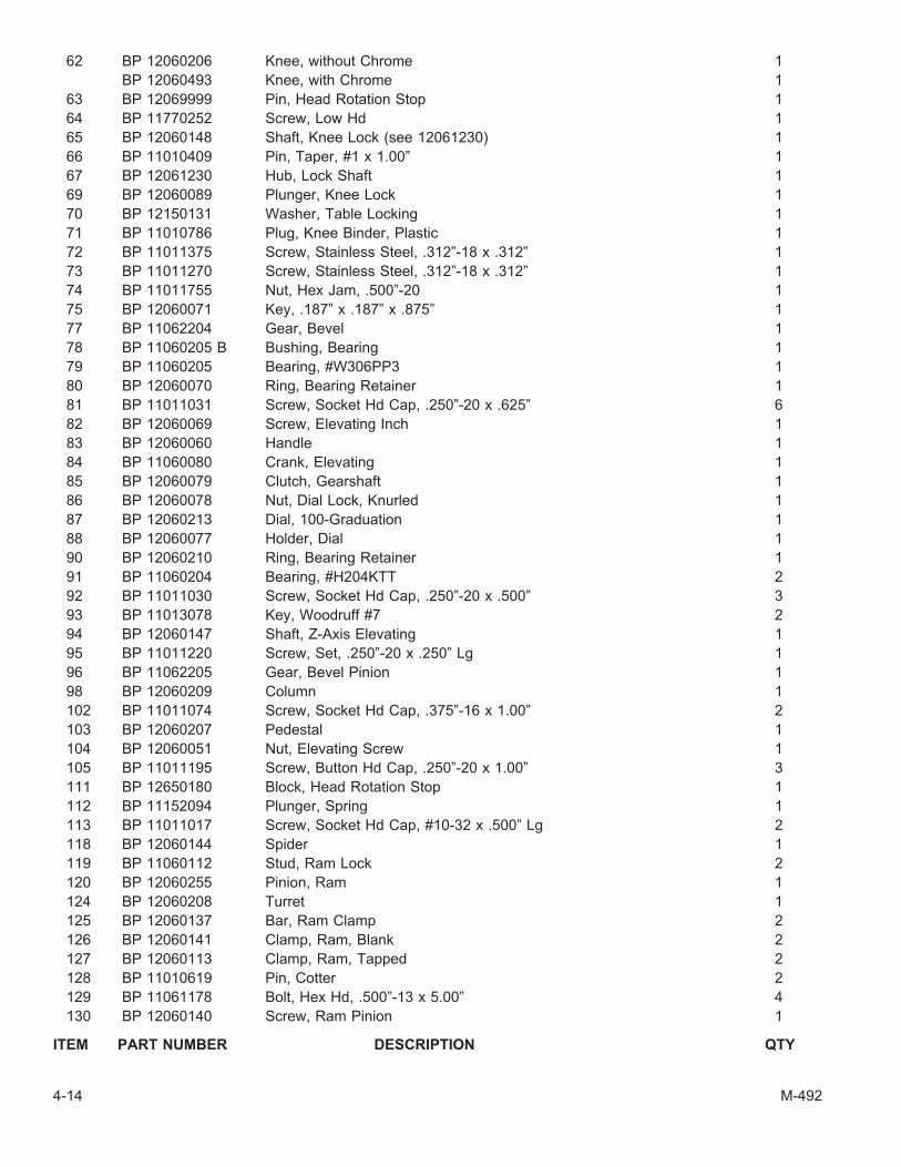
62 BP 12060206 Knee, without Chrome 1
BP 12060493 Knee, with Chrome 1
63 BP 12069999 Pin, Head Rotation Stop 1
64 BP 11770252 Screw, Low Hd 1
65 BP 12060148 Shaft, Knee Lock (see 12061230) 1
66 BP 11010409 Pin, Taper, #1 x 1.00” 1
67 BP 12061230 Hub, Lock Shaft 1
69 BP 12060089 Plunger, Knee Lock 1
70 BP 12150131 Washer, Table Locking 1
71 BP 11010786 Plug, Knee Binder, Plastic 1
72 BP 11011375 Screw, Stainless Steel, .312”-18 x .312” 1
73 BP 11011270 Screw, Stainless Steel, .312”-18 x .312” 1
74 BP 11011755 Nut, Hex Jam, .500”-20 1
75 BP 12060071 Key, .187” x .187” x .875” 1
77 BP 11062204 Gear, Bevel 1
78 BP 11060205 B Bushing, Bearing 1
79 BP 11060205 Bearing, #W306PP3 1
80 BP 12060070 Ring, Bearing Retainer 1
81 BP 11011031 Screw, Socket Hd Cap, .250”-20 x .625” 6
82 BP 12060069 Screw, Elevating Inch 1
83 BP 12060060 Handle 1
84 BP 11060080 Crank, Elevating 1
85 BP 12060079 Clutch, Gearshaft 1
86 BP 12060078 Nut, Dial Lock, Knurled 1
87 BP 12060213 Dial, 100-Graduation 1
88 BP 12060077 Holder, Dial 1
90 BP 12060210 Ring, Bearing Retainer 1
91 BP 11060204 Bearing, #H204KTT 2
92 BP 11011030 Screw, Socket Hd Cap, .250”-20 x .500” 3
93 BP 11013078 Key, Woodruff #7 2
94 BP 12060147 Shaft, Z-Axis Elevating 1
95 BP 11011220 Screw, Set, .250”-20 x .250” Lg 1
96 BP 11062205 Gear, Bevel Pinion 1
98 BP 12060209 Column 1
102 BP 11011074 Screw, Socket Hd Cap, .375”-16 x 1.00” 2
103 BP 12060207 Pedestal 1
104 BP 12060051 Nut, Elevating Screw 1
105 BP 11011195 Screw, Button Hd Cap, .250”-20 x 1.00” 3
111 BP 12650180 Block, Head Rotation Stop 1
112 BP 11152094 Plunger, Spring 1
113 BP 11011017 Screw, Socket Hd Cap, #10-32 x .500” Lg 2
118 BP 12060144 Spider 1
119 BP 11060112 Stud, Ram Lock 2
120 BP 12060255 Pinion, Ram 1
124 BP 12060208 Turret 1
125 BP 12060137 Bar, Ram Clamp 2
126 BP 12060141 Clamp, Ram, Blank 2
127 BP 12060113 Clamp, Ram, Tapped 2
128 BP 11010619 Pin, Cotter 2
129 BP 11061178 Bolt, Hex Hd, .500”-13 x 5.00” 4
130 BP 12060140 Screw, Ram Pinion 1
ITEM PART NUMBER DESCRIPTION QTY
4-14 M-492

131 BP 11060602 Scale, Ram 1
BP 11980426 Screw, Drive, Type U, #4 x .312” 2
132 BP 11060601 Turret, Scale 1
BP 11989426 Screw, Drive 2
133 BP 11010200 Nameplate, Warning 1
BP 11980426 Screw, Drive, Type U, #4 x .312” 4
M-492 4-15

SPRAY MIST
ITEM PART NUMBER DESCRIPTION QTY
1 BP 11560085 Tank, Spray Mist, 1 Gal Cap, 110-120v-50/60 Hz 1
1 BP 11560095 Tank, Spray Mist, 5 Gal Cap, 110-120v-50/60 Hz 1
2 BP 11151987 Washer 2
3 BP 11011477 Screw, Round Hd Machine, .250”-20 x 1.00” 2
4 BP 11560087 Assembly, Dual Hose, 6 ft 1
ONE NOZZLE
7 BP 11560091 Holder, Magnetic Jet 1
8 BP 11560086 Jet, Flexible Extension 1
TWO NOZZLES
5 BP 11560092 Block, Tee 1
6 BP 11560093 Hose, 24” 2
7 BP 11560091 Holder, Magnetic Jet 2
8 BP 11560086 Jet, Flexible Extension 2
9 BP 11011040 Screw, Socket Hd Cap, .250”-20 x 1.750” 2
4-16 M-492
Figure 4.5 - Spray Mist Assembly
TP5346

FLOOD COOLANT
ITEM PART NUMBER DESCRIPTION QTY
1 11713642 Tank, Pump and Motor 1
2 11715470 Tubing, Coolant Pressure Hose, Vinyl, .50”� x .625” 10 ft
3 11565476 Valve, Check 1
4 12561010 Block, Manifold 1
7 11565470 Tubing, Drain Hose, Vinyl, .750” x 1000” 15 ft
ONE NOZZLE
5 11563490 Valve, Shut-Off 1
6 11560264 Hose, Flexible Nozzle Coolant, 21” Lg 1
TWO NOZZLES
5 11563490 Valve, Shut-Off 2
6 11560264 Hose, Flexible Nozzle Coolant, 21” Lg 2
M-492 4-17
Figure 4.6 - Flood Coolant Assembly
TP5347

LUBRICATION SYSTEM
4-18 M-492
Figure 4.7 - Lubrication System Assembly
TP5348

LUBRICATION SYSTEM
ITEM PART NUMBER DESCRIPTION QTY
1* BP 11413210 Unit, Metering, Bijur #B-2495 3
2* BP 11413211 Unit, Metering, #FJB-1, B-2496 6
3 BP 11413226 Plug, Closure, #B-3784 1
4 BP 11413220 Bushing, Compression, Bijur #1371 11
5 BP 11413221 Sleeve, Compression, Bijur #B-8272 11
6 BP 11413224 Tubing, Brass, .156” 1
7 BP 11413225 Tubing, Nylon, .156” to suit
8 BP 11413222 Connector, 90� EL 2
9 BP 11410017 Junction, 4-Way 1
10 BP 11413219 Nut, Compression 11
11 BP 11413293 Bushing, Compression Sleeve 1
12 BP 11410053 Hose, Flexible, 18” Lg 1
13 BP 11413230 Bracket, Hose 1
14 BP 11413233 Nut, Terminal 1
15 BP 11011475 Screw, Round Hd Machine, .250”-20 x .500” 1
16 BP 11413236 Clip, Tubing, #B-7535 2
17 BP 11413290 Clip, Tubing, #A-2435 1
18 BP 11410063 Junction, 10-Way 1
19 BP 11011420 Screw, Round Hd Machine, #8-32 x .250” 3
20 BP 11413235 Bushing, Drive 8
21 BP 11011194 Screw, Button Hd Cap, .250”-20 x .5.00” 2
22 BP 11011195 Screw, Button Hd Cap, .250”-20 x 1.00” 2
23 BP 11413209 Pump, Auto Lube 1
BP 11410324 Pump, One Shot Lube, Manual 1
- CAUTION -
When replacing metering units be sure you replace with correct numbermeter units. An incorrect installation will cause poor lubrication.
M-492 4-19

ACU-RITE MILLPWR CONTROL COMPONENTS
X AXIS HANDLE ASSEMBLY
4-20 M-492
Figure 4.8 - X Axis Handle Assembly
TP7240
1 2
3
4
5
6
7
8910
11
12

X AXIS HANDLE ASSEMBLY
ITEM PART NUMBER DESCRIPTION QTY
1 BP 12060115 Guide, Ballscrew 1
2 BP 11011074 SHCS, 3/8-16 x 1" 4
3 BP 12060084 Holder, Dial 1
4 BP 11060214 Dial 1
5 BP 12060078 Nut, Lock 1
6 TL 0006278 Key, 1/8" SQ. x 1" 1
7 0310616 FHCS, ¼-20 x 1" 1
8 BP 115911030053 Washer, Retaining 1
10 BP 115911030047 Washer, Shim .03" 1
11 BP 115911030006 Washer, Arbor 1
12 BP 115911030045 Spacer, 1" 1
M-492 4-21

X AXIS MOTOR ASSEMBLY
4-22 M-492
Figure 4.9 - X Axis Motor Assembly
TP7241
1
2
3
4
5
6
7
8
9
10
11
12
13
14
15
16
17
18
19
20
21
22
23
24
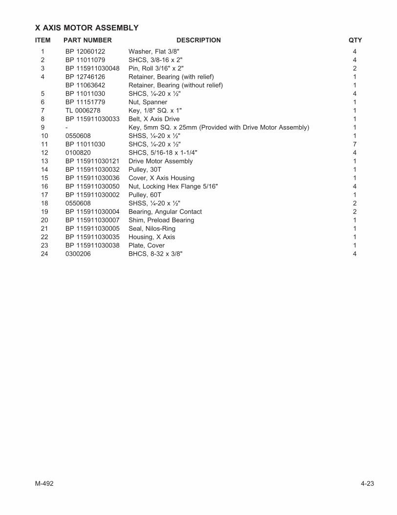
X AXIS MOTOR ASSEMBLY
ITEM PART NUMBER DESCRIPTION QTY
1 BP 12060122 Washer, Flat 3/8" 4
2 BP 11011079 SHCS, 3/8-16 x 2" 4
3 BP 115911030048 Pin, Roll 3/16" x 2" 2
4 BP 12746126 Retainer, Bearing (with relief) 1
BP 11063642 Retainer, Bearing (without relief) 1
5 BP 11011030 SHCS, ¼-20 x ½" 4
6 BP 11151779 Nut, Spanner 1
7 TL 0006278 Key, 1/8" SQ. x 1" 1
8 BP 115911030033 Belt, X Axis Drive 1
9 - Key, 5mm SQ. x 25mm (Provided with Drive Motor Assembly) 1
10 0550608 SHSS, ¼-20 x ½" 1
11 BP 11011030 SHCS, ¼-20 x ½" 7
12 0100820 SHCS, 5/16-18 x 1-1/4" 4
13 BP 115911030121 Drive Motor Assembly 1
14 BP 115911030032 Pulley, 30T 1
15 BP 115911030036 Cover, X Axis Housing 1
16 BP 115911030050 Nut, Locking Hex Flange 5/16" 4
17 BP 115911030002 Pulley, 60T 1
18 0550608 SHSS, ¼-20 x ½" 2
19 BP 115911030004 Bearing, Angular Contact 2
20 BP 115911030007 Shim, Preload Bearing 1
21 BP 115911030005 Seal, Nilos-Ring 1
22 BP 115911030035 Housing, X Axis 1
23 BP 115911030038 Plate, Cover 1
24 0300206 BHCS, 8-32 x 3/8" 4
M-492 4-23
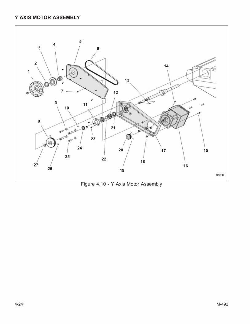
Y AXIS MOTOR ASSEMBLY
4-24 M-492
Figure 4.10 - Y Axis Motor Assembly
TP7242
1
2
34
5
6
7
8
9
1011
12
13
14
15
16
17
18
19
20
21
22
23
24
25
2627

Y AXIS MOTOR ASSEMBLY
ITEM PART NUMBER DESCRIPTION QTY
1 BP 115911030046 Handwheel 1
2 BP 12060078 Nut, Lock 1
3 BP 11060214 Dial 1
4 BP 12060084 Holder, Dial 1
5 BP 115911030003 Cover, Y Axis Housing 1
6 BP 115911030034 Belt, Y Axis Drive 1
7 0100308 SHCS, 10-32 x ½" 6
8 BP 115911030002 Pulley, 60T 1
9 BP 12060122 Washer, Flat 3/8" 4
10 BP 11010543 Pin, Roll 3/16" x 1" 2
11 BP 12746126 Retainer, Bearing (with relief) 1
BP 11063642 Retainer, Bearing (without relief) 1
12 BP 115911030004 Bearing, Angular Contact 2
13 TL 0006278 Key, 1/8" SQ. x 1" 2
14 - Key, 5mm SQ. x 25mm (Provided with Drive Motor Assembly) 1
15 0100820 SHCS, 5/16-18 x 1-1/4" 4
16 BP 115911030121 Drive Motor Assembly 1
17 BP 115911030037 Housing, Y Axis 1
18 BP 115911030050 Nut, Locking Hex Flange 5/16" 1
19 0550608 SHSS, ¼-20 x ½" 1
20 BP 115911030032 Pulley, 30T 1
21 BP 115911030005 Seal, Nilos-Ring 1
22 BP 115911030007 Shim, Preload Bearing 1
23 BP 11011030 SHCS, ¼-20 x ½" 3
24 BP 11151779 Nut, Spanner 1
25 BP 11011074 SHCS, 3/8-16 x 1" 1
26 0550608 SHSS, ¼-20 x ½" 2
27 BP 115911030006 Washer, Arbor 1
M-492 4-25

Z AXIS ASSEMBLY (View 1)
4-26 M-492
Figure 4.11 - Z Axis Assembly: View 1
TP7246
1
2
5
4
6
7
9
10
11
3
8
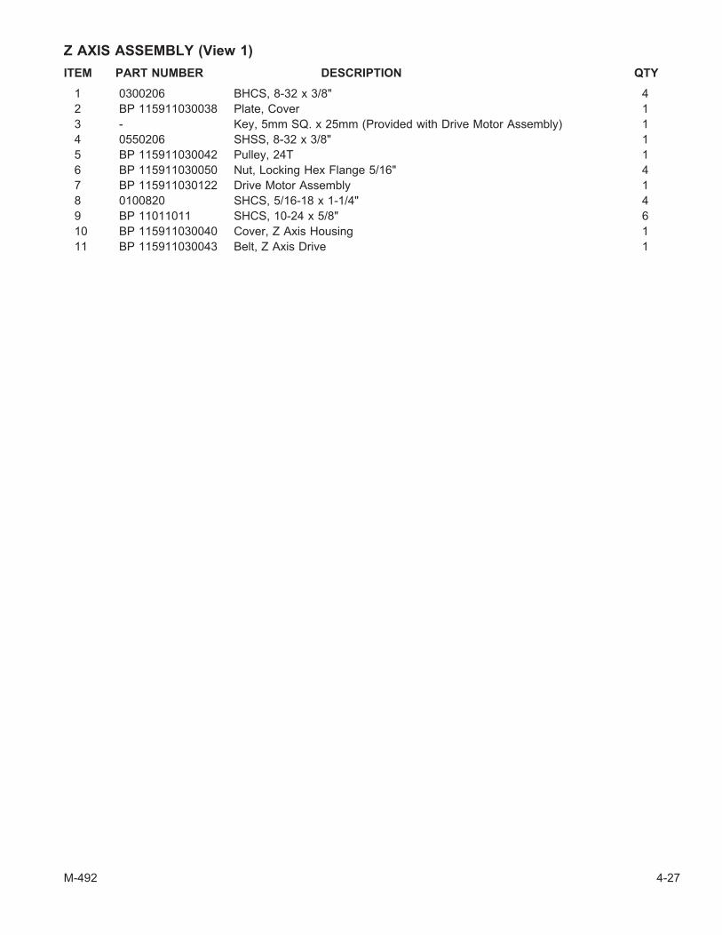
Z AXIS ASSEMBLY (View 1)
ITEM PART NUMBER DESCRIPTION QTY
1 0300206 BHCS, 8-32 x 3/8" 4
2 BP 115911030038 Plate, Cover 1
3 - Key, 5mm SQ. x 25mm (Provided with Drive Motor Assembly) 1
4 0550206 SHSS, 8-32 x 3/8" 1
5 BP 115911030042 Pulley, 24T 1
6 BP 115911030050 Nut, Locking Hex Flange 5/16" 4
7 BP 115911030122 Drive Motor Assembly 1
8 0100820 SHCS, 5/16-18 x 1-1/4" 4
9 BP 11011011 SHCS, 10-24 x 5/8" 6
10 BP 115911030040 Cover, Z Axis Housing 1
11 BP 115911030043 Belt, Z Axis Drive 1
M-492 4-27

Z AXIS ASSEMBLY (View 2)
4-28 M-492
Figure 4.12 - Z Axis Assembly: View 2
TP7245
2
1
3
45
67
8
9
10
11
13
12
14
15
16

Z AXIS ASSEMBLY (View 2)
ITEM PART NUMBER DESCRIPTION QTY
1 BP 115911030054 Clamp, ¼" Cable 1
0110106 PHMS, 6-32 x 3/8" 1
2 0300306 BHCS, 10-32 x 3/8" 1
3 0119208 PHMS, 2-56 x ½" 2
4 BP 115911030019 Holder, Switch 2
5 BP 115911030020 Switch, Limit 1
BP 115911030031 Assembly, Cable 1
6 0119208 PHMS, 2-56 x ½" 2
7 0110004 PHMS, 4-40 x ¼" 4
8 BP 11011011 SHCS, 10-24 x 5/8" 5
9 BP 115911030025 Label, Warning 1
10 BP 115911030041 Plate, Cover 1
11 BP 115911030023 Brush, Nylon (Not Shown) 2
BP 115911030044 Bracket, Clamping (Not Shown) 4
0300107 BHCS, 6-32 x 7/16" (Not Shown) 4
12 BP 115911030013 Holder, Switch (Not Shown) 1
0110406 PHMS, 10-24 x 3/8" (Not Shown) 2
0100308 SHCS, 10-32 x ½" (Not Shown) 2
13 BP 115911030049 Wire Assembly, Limit Switch 1
14 0100104 SHCS, 6-32 x ¼" 2
15 BP 115911030020 Switch, Limit 1
16 BP 115911030001 Pointer 1
M-492 4-29
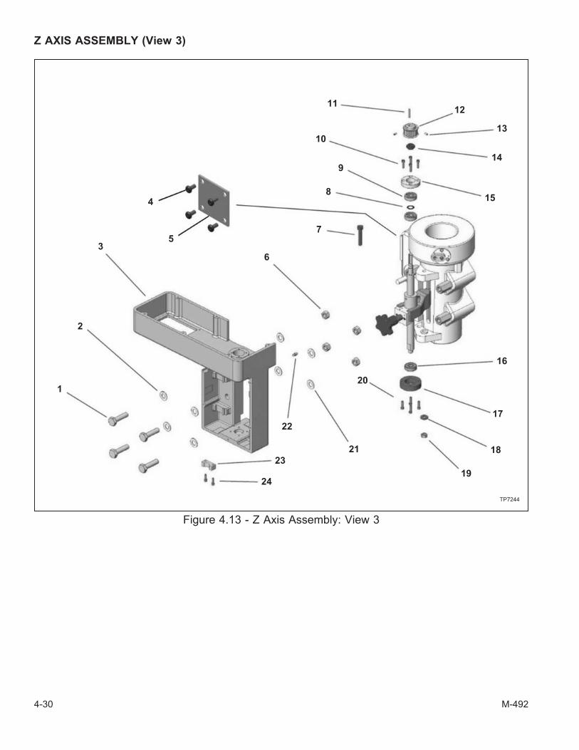
Z AXIS ASSEMBLY (View 3)
4-30 M-492
Figure 4.13 - Z Axis Assembly: View 3
TP7244
2
1
3
4
5
6
7
8
9
10
1112
13
14
15
16
17
18
19
20
21
22
23
24
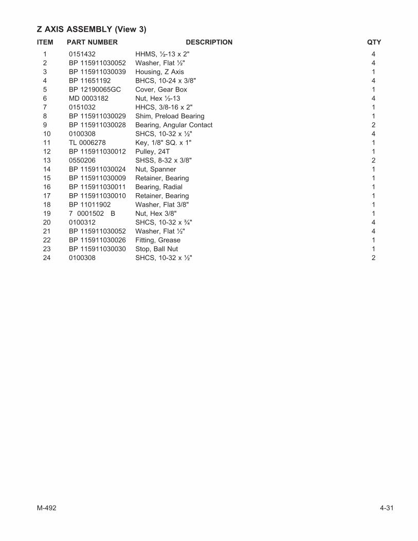
Z AXIS ASSEMBLY (View 3)
ITEM PART NUMBER DESCRIPTION QTY
1 0151432 HHMS, ½-13 x 2" 4
2 BP 115911030052 Washer, Flat ½" 4
3 BP 115911030039 Housing, Z Axis 1
4 BP 11651192 BHCS, 10-24 x 3/8" 4
5 BP 12190065GC Cover, Gear Box 1
6 MD 0003182 Nut, Hex ½-13 4
7 0151032 HHCS, 3/8-16 x 2" 1
8 BP 115911030029 Shim, Preload Bearing 1
9 BP 115911030028 Bearing, Angular Contact 2
10 0100308 SHCS, 10-32 x ½" 4
11 TL 0006278 Key, 1/8" SQ. x 1" 1
12 BP 115911030012 Pulley, 24T 1
13 0550206 SHSS, 8-32 x 3/8" 2
14 BP 115911030024 Nut, Spanner 1
15 BP 115911030009 Retainer, Bearing 1
16 BP 115911030011 Bearing, Radial 1
17 BP 115911030010 Retainer, Bearing 1
18 BP 11011902 Washer, Flat 3/8" 1
19 7 0001502 B Nut, Hex 3/8" 1
20 0100312 SHCS, 10-32 x ¾" 4
21 BP 115911030052 Washer, Flat ½" 4
22 BP 115911030026 Fitting, Grease 1
23 BP 115911030030 Stop, Ball Nut 1
24 0100308 SHCS, 10-32 x ½" 2
M-492 4-31
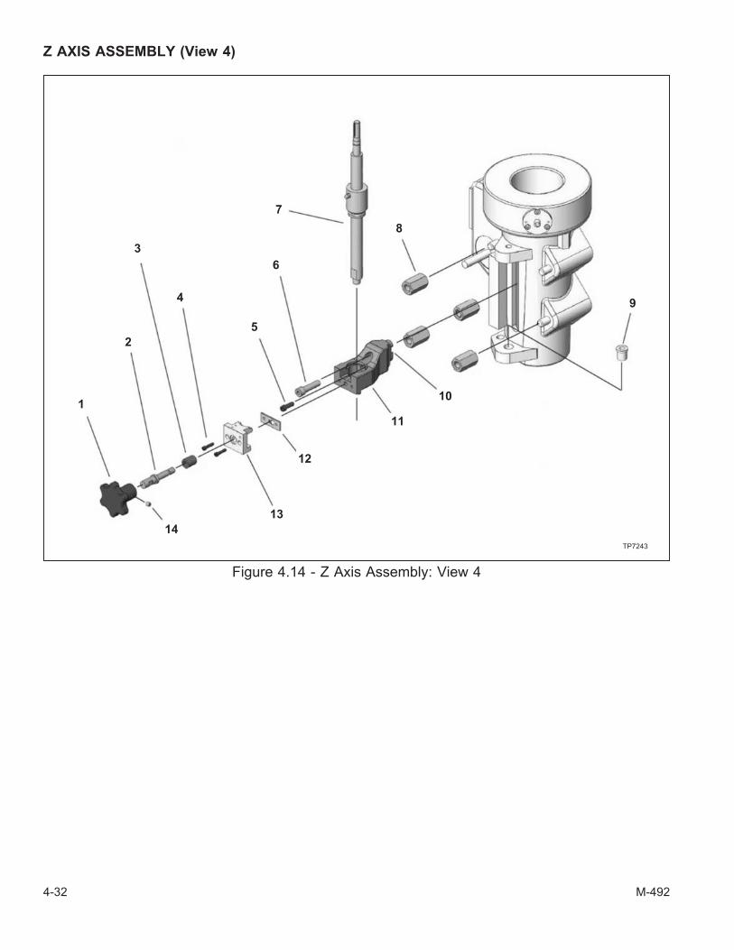
Z AXIS ASSEMBLY (View 4)
4-32 M-492
Figure 4.14 - Z Axis Assembly: View 4
TP7243
1
2
3
4
5
6
7
8
9
10
11
12
13
14

Z AXIS ASSEMBLY (View 4)
ITEM PART NUMBER DESCRIPTION QTY
1 BP 115911030022 Knob, Quick Release 1
2 BP 115911030017 Shaft 1
3 BP 115911030027 Spacer 1
4 0100212 SHCS, 8-32 x ¾" 2
5 0100612 SHCS, ¼-20 x ¾" 1
6 0100924 SHCS, 3/8-24 x 1-1/2" 1
7 BP 115911030008 Ball Screw 1
8 BP 115911030051 Nut, ½-13 External Hex Coupling 4
9 BP 115911030021 Bushing, Alignment 1
10 BP 115911030055 Key, Drive 1
11 BP 115911030014 Block, Nut 1
12 BP 115911030018 Retainer, Shaft 1
13 BP 115911030016 Clamp 1
14 0550604 SHSS, ¼-20 x ¼" 1
M-492 4-33

CONTROL MOUNTING BRACKET
4-34 M-492
Figure 4.15 - Control Mounting Bracket
TP7254
2
1
3
4
5
6
7
8
9
10
11
12
14
13
15
1617
18
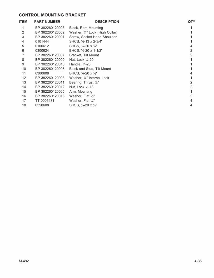
CONTROL MOUNTING BRACKET
ITEM PART NUMBER DESCRIPTION QTY
1 BP 382260120003 Block, Ram Mounting 1
2 BP 382260120002 Washer, ¾" Lock (High Collar) 1
3 BP 382260120001 Screw, Socket Head Shoulder 1
4 0101444 SHCS, ½-13 x 2-3/4" 1
5 0100612 SHCS, ¼-20 x ¾" 4
6 0300624 BHCS, ¼-20 x 1-1/2" 2
7 BP 382260120007 Bracket, Tilt Mount 2
8 BP 382260120009 Nut, Lock ¼-20 1
9 BP 382260120010 Handle, ¼-20 1
10 BP 382260120006 Block and Stud, Tilt Mount 1
11 0300608 BHCS, ¼-20 x ½" 4
12 BP 382260120008 Washer, ¼" Internal Lock 1
13 BP 382260120011 Bearing, Thrust ½" 2
14 BP 382260120012 Nut, Lock ½-13 2
15 BP 382260120005 Arm, Mounting 1
16 BP 382260120013 Washer, Flat ½" 2
17 TT 0006431 Washer, Flat ¼" 4
18 0550608 SHSS, ¼-20 x ½" 4
M-492 4-35

SPINDLE CONTROL CASE (View 1)
4-36 M-492
Figure 4.16 - Spindle Control Case: View 1
TP7264
1
23
4
5
6
78
9
13
14
16
15
17
21
19
20
18
22

SPINDLE CONTROL CASE (View 1)
ITEM PART NUMBER DESCRIPTION QTY
1 BP 115911030064 Enclosure, Spindle Control 1
2 BP 115911030059 Wraparound, Filter 1
3 BP 115911030058 Cover, Filter 1
4 BP 115911030060 Plate, Louver 1
5 BP 115911030097 Fan 1
6 BP 115911030098 Fingerguard, Fan 1
7 BP 115911030099 Standoff, 6-32 x 3/8" Long Hex 4
8 BP 115911030075 Gasket, Neoprene U-Channel 1
9 BP 115911030095 Filter, Air 1
13 BP 115911030110 Hinge, In-Line Knuckle 2
14 SL 0008137 Washer, #6 External Star Lock 4
15 0110130 Screw, PHMS 6-32 x 1 7/8" 4
16 0110106 Screw, PHMS 6-32 x 3/8" 4
17 BP 115911030096 Filter, Servo Vent 1
18 BP 115911030106 Nut, Wing 6-32 Type A 4
19 0300306 Screw, Machine 10-32 x 3/8" 4
20 BP 115911030108 Plug, Nylon .875" x .12" 8
21 BP 115911030109 Plug, Nylon 1.13" x .13" 1
22 BP 115911030102 Screw, 10-32 x 3/8" w/Star Washer 4
M-492 4-37
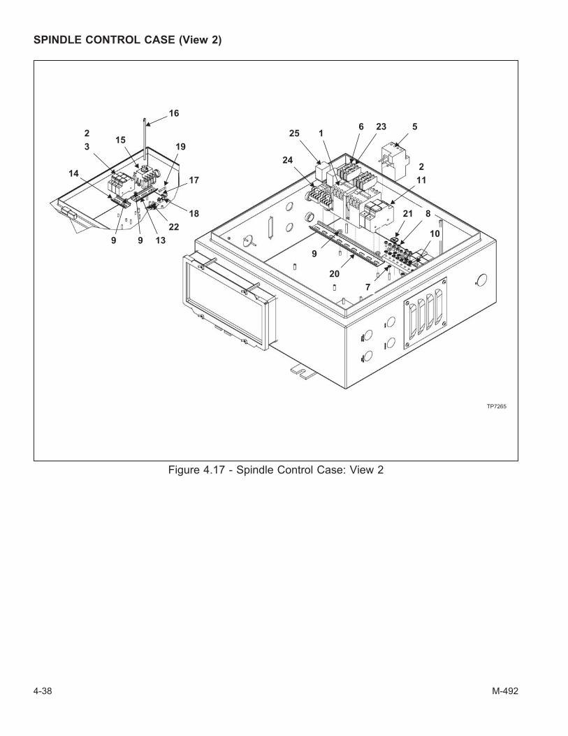
SPINDLE CONTROL CASE (View 2)
4-38 M-492
Figure 4.17 - Spindle Control Case: View 2
TP7265
16
19
17
18
22
139
153
14
2
9
24
25 16 23 5
2
11
21 8
10
7
20
9
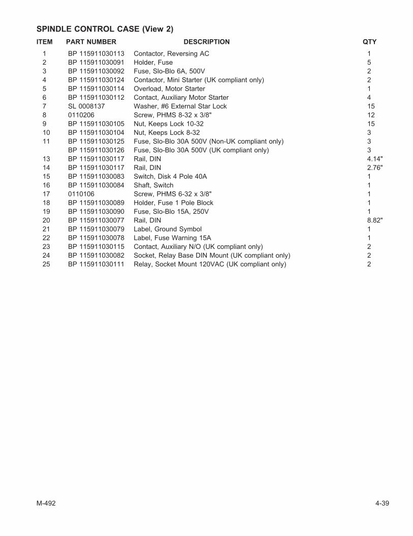
SPINDLE CONTROL CASE (View 2)
ITEM PART NUMBER DESCRIPTION QTY
1 BP 115911030113 Contactor, Reversing AC 1
2 BP 115911030091 Holder, Fuse 5
3 BP 115911030092 Fuse, Slo-Blo 6A, 500V 2
4 BP 115911030124 Contactor, Mini Starter (UK compliant only) 2
5 BP 115911030114 Overload, Motor Starter 1
6 BP 115911030112 Contact, Auxiliary Motor Starter 4
7 SL 0008137 Washer, #6 External Star Lock 15
8 0110206 Screw, PHMS 8-32 x 3/8" 12
9 BP 115911030105 Nut, Keeps Lock 10-32 15
10 BP 115911030104 Nut, Keeps Lock 8-32 3
11 BP 115911030125 Fuse, Slo-Blo 30A 500V (Non-UK compliant only) 3
BP 115911030126 Fuse, Slo-Blo 30A 500V (UK compliant only) 3
13 BP 115911030117 Rail, DIN 4.14"
14 BP 115911030117 Rail, DIN 2.76"
15 BP 115911030083 Switch, Disk 4 Pole 40A 1
16 BP 115911030084 Shaft, Switch 1
17 0110106 Screw, PHMS 6-32 x 3/8" 1
18 BP 115911030089 Holder, Fuse 1 Pole Block 1
19 BP 115911030090 Fuse, Slo-Blo 15A, 250V 1
20 BP 115911030077 Rail, DIN 8.82"
21 BP 115911030079 Label, Ground Symbol 1
22 BP 115911030078 Label, Fuse Warning 15A 1
23 BP 115911030115 Contact, Auxiliary N/O (UK compliant only) 2
24 BP 115911030082 Socket, Relay Base DIN Mount (UK compliant only) 2
25 BP 115911030111 Relay, Socket Mount 120VAC (UK compliant only) 2
M-492 4-39

SPINDLE CONTROL CASE (View 3)
4-40 M-492
Figure 4.18 - Spindle Control Case: View 3
TP7266
13
12
7
28 4
8
5 9
11
7
1

SPINDLE CONTROL CASE (View 3)
ITEM PART NUMBER DESCRIPTION QTY
1 BP 115911030056 Assembly, AMI PCB 1
2 BP 115911030057 Assembly, SCI PCB (UK compliant only) 1
4 BP 115911030069 Assembly, Harness, Work Light/Pump (UK compliant only) 1
5 BP 115911030068 Assembly, Harness, Guard (UK compliant only) 1
6 BP 115911030070 Assembly, Harness, AMI 1
7 0110106 Screw, PHMS 6-32 x 3/8" 9
8 BP 115911030103 Nut, Keeps Lock 6-32 (UK compliant only) 4
9 BP 115911030081 Connector, Mounting Hareware 1
11 BP 115911030071 Assembly, Power Cord Harness 1
12 BP 115911030067 Interface PCB, Spindle Control 1
13 BP 115911030074 Relay, PCB Mount G2R-24 (UK compliant only) 2
M-492 4-41
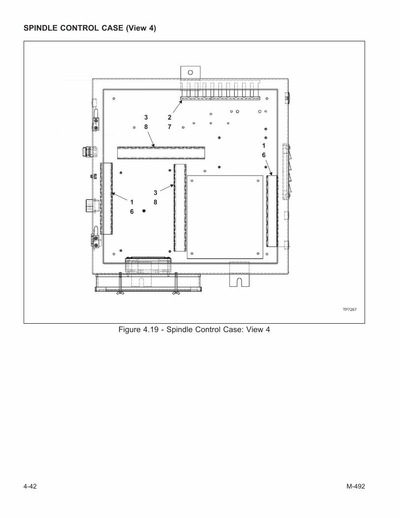
SPINDLE CONTROL CASE (View 4)
4-42 M-492
Figure 4.19 - Spindle Control Case: View 4
TP7267
2
7
3
81
6
3
8
1
6

SPINDLE CONTROL CASE (View 4)
ITEM PART NUMBER DESCRIPTION QTY
1 BP 115911030119 Cover, Wireway 7.3"
2 BP 115911030119 Cover, Wireway 8.0"
3 BP 115911030119 Cover, Wireway 9.8"
6 BP 115911030120 Wireway 7.3"
7 BP 115911030120 Wireway 8.0"
8 BP 115911030120 Wireway 9.8"
M-492 4-43

SPINDLE CONTROL CASE (View 5)
4-44 M-492
Figure 4.20 - Spindle Control Case: View 5
TP7268
2
17
3
6
54

SPINDLE CONTROL CASE (View 5)
ITEM PART NUMBER DESCRIPTION QTY
1 BP 115911030065 Door, Spindle Control Enclosure 1
2 BP 115911030076 Gasket, Neoprene 1
3 BP 115911030110 Hinge, In-Line Knuckle 2
4 BP 115911030061 Latch, Door 2
5 0110204 Screw, PHMS 8-32 x 1/4" 2
6 BP 115911030102 Screw, 10-32 x 3/8" w/Star Washer 2
7 BP 115911030083 Switch, Disk 4 Pole 40A 1
M-492 4-45

SPINDLE CONTROL CASE (View 6)
4-46 M-492
Figure 4.21 - Spindle Control Case: View 6
TP7269
3
1
2

SPINDLE CONTROL CASE (View 6)
ITEM PART NUMBER DESCRIPTION QTY
1 BP 115911030118 Transformer, Step-Down 2KVA 1
2 BP 115911030107 Washer, Flat #10 SAE 4
3 BP 115911030105 Nut, Keeps Lock 10-32 4
M-492 4-47
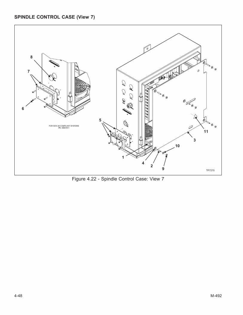
SPINDLE CONTROL CASE (View 7)
4-48 M-492
Figure 4.22 - Spindle Control Case: View 7
TP7270
8
7
6
5
1
42
9
10
3
11

SPINDLE CONTROL CASE (View 7)
ITEM PART NUMBER DESCRIPTION QTY
1 BP 115911030100 Standoff, 10-32 x 7" Long, 1/2" Hex (UK compliant only) 5
2 0550316 Screw, SHSS 10-32 x 1" (UK compliant only) 5
3 BP 115911030066 Shield, Plexi-Glass (UK compliant only) 1
4 BP 115911030101 Grommet, .63" OD x .25" ID x .25" (UK compliant only) 5
5 BP 115911030093 Plate, Weatherproof Cover (UK compliant only) 1
6 0110112 Screw, PHMS 6-32 x 3/4" Black (Non-UK compliant only) 4
7 BP 115911030094 Plate, Weatherproof Blank Cover (Non-UK compliant only) 1
8 BP 115911030109 Plug, Nylon 1.13" x .13" (Non-UK compliant only) 1
9 BP 115911030105 Nut, Keeps Lock 10-32 (UK compliant only) 5
10 BP 115911030107 Washer, Flat #10 SAE (UK compliant only) 5
11 BP 115911030080 Label, Electrical Hazard (UK compliant only) 1
M-492 4-49
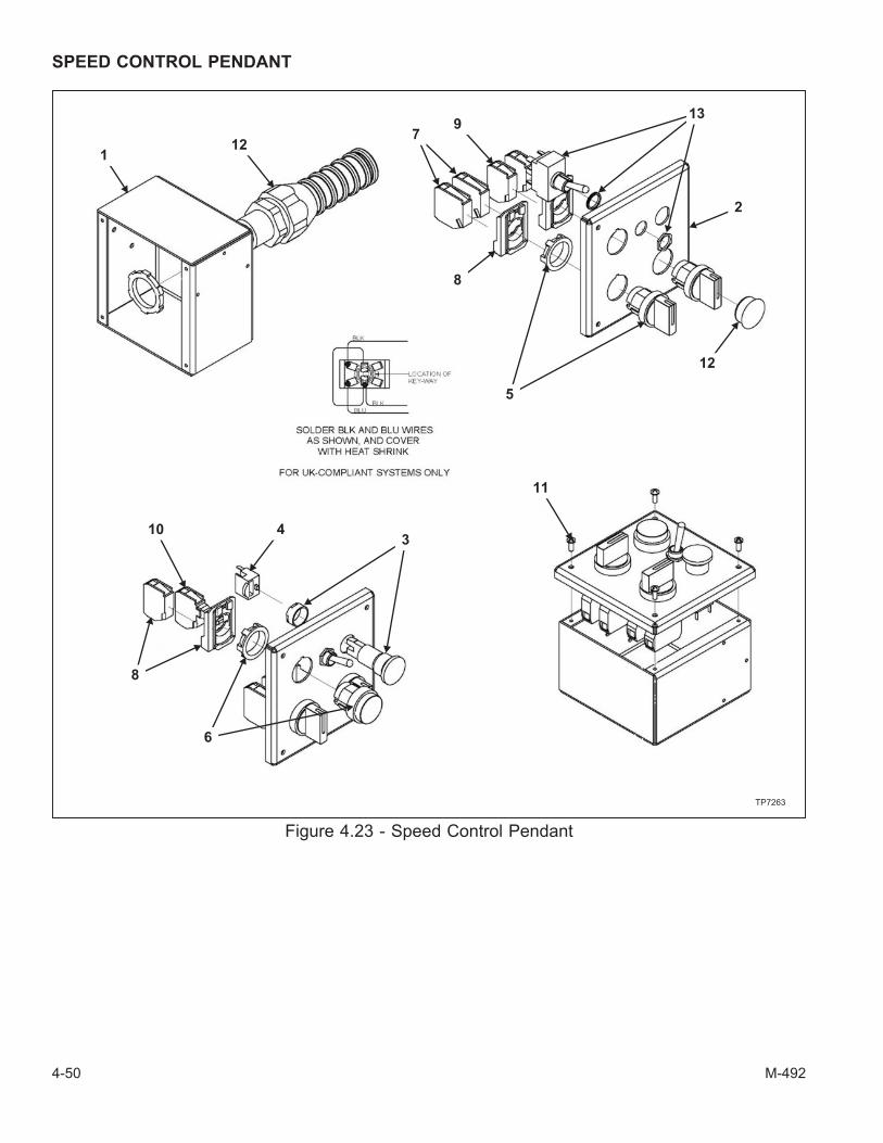
SPEED CONTROL PENDANT
4-50 M-492
Figure 4.23 - Speed Control Pendant
112
79
13
2
8
5
12
11
10
8
43
6
TP7263

SPEED CONTROL PENDANT
- NOTE -
There are two versions of the UK-compliant pendant interface harness assemblylisted as item 13. Refer to the MILLPWR control serial number to determine the cor-rect harness assembly.
Controls with serial numbers 0607-xxxx and earlier use the harness assembly desig-nated "version 1".
Controls with serial numbers after 0607-xxxx use the harness assembly designated"version 2".
ITEM PART NUMBER DESCRIPTION QTY
1 BP 115911030062 Enclosure, Spindle Control Pendant 1
2 BP 115911030063 Cover, Pendant Enclosure 1
3 BP 115911030072 Switch, Emergency Stop 1
4 BP 115911030073 Contact, Emergency Stop Switch 1
5 BP 115911030085 Switch, 3 Position Selector (Non-UK compliant only) 1
BP 115911030085 Switch, 3 Position Selector (UK compliant only) 2
6 BP 115911030086 Switch, Push Button Illum. Green 1
7 BP 115911030116 Contact Block, Switch 2
8 BP 115911030087 Block, Contact with Mount (Non-UK compliant only) 1
BP 115911030087 Block, Contact with Mount (UK compliant only) 2
9 BP 115911030123 Contact Block, Switch 1
10 BP 115911030088 Module, Green LED with Contact Block 1
11 0110106 Screw, PHMS 6-32 x 3/8" 4
12 BP 115911030108 Plug, Nylon .875" x .12" (Non-UK compliant only) 1
13 BP 115911030129 Assembly, Harness Pendant Interface (Non-UK compliant only) 1
BP 115911030127 Assembly, Harness Pendant Interface (UK compliant, version 1 only) 1
BP 115911030128 Assembly, Harness Pendant Interface (UK compliant, version 2 only) 1
M-492 4-51

- NOTES -
4-52 M-492

CHAPTER 5 - SPECIFICATIONS
PRINCIPLE DIMENSIONS
A B C D E F
MIN 82” (2083) 51” (1295) 8.750” (222) 2.500” (64) 0 6.750” (171)MAX 82” (2083) 63” (1600) 20.750” (527) 18.500” (470) 12” (305) 18.750” (476)
Note: Metric specifications in parenthesis
M-492 5-1
Figure 5.1 - Machine Dimensions: Left Side View
TP5264
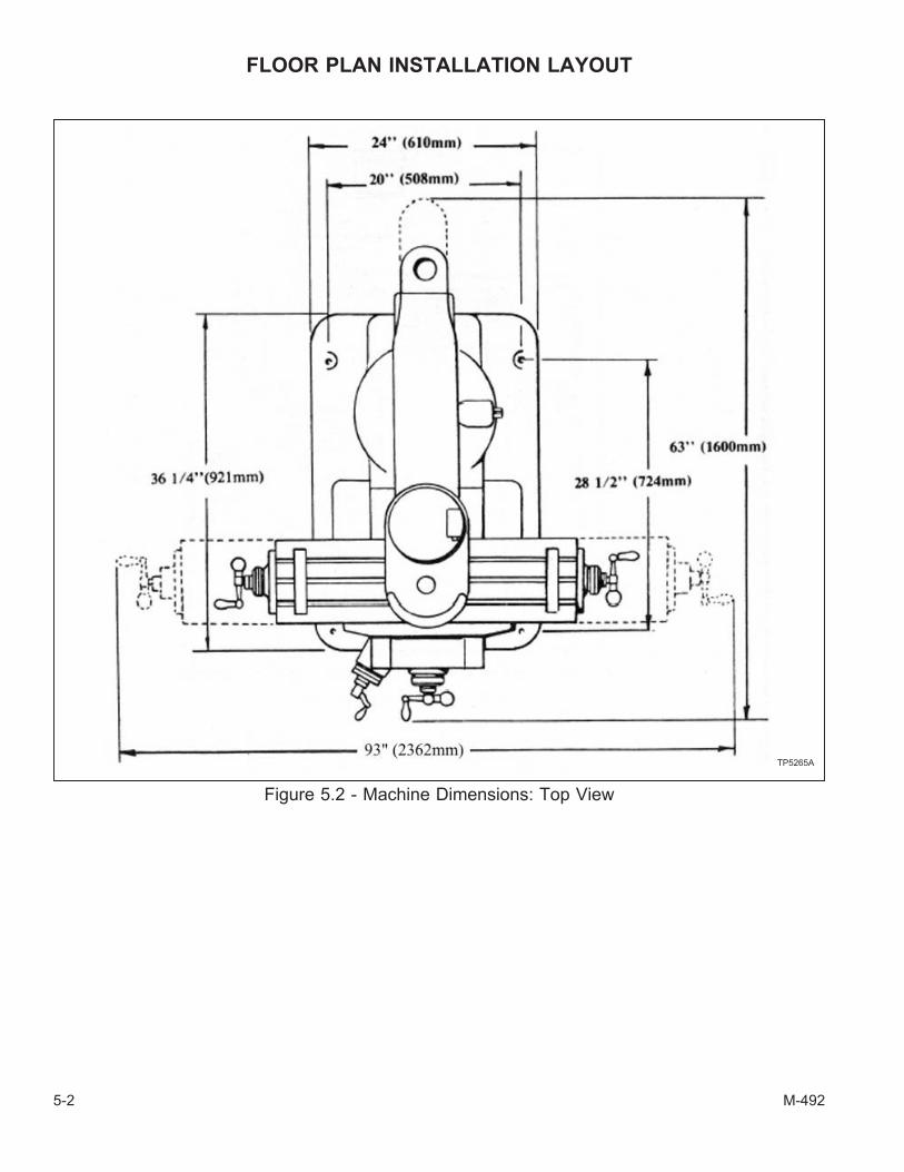
FLOOR PLAN INSTALLATION LAYOUT
5-2 M-492
Figure 5.2 - Machine Dimensions: Top View
TP5265A

M-492 5-3
Figure 5.3 - Machine Dimensions:Right Side View
TP5266
Figure 5.4 - Machine Dimensions:Front View
TP5267A
Figure 5.5 - Hold-Down Bolt
TP5383
5-3/4”
(146mm)
5/8”� (16mm)

MACHINE SPECIFICATIONS
RANGE
Table Travel (X-Axis) 30” [762 mm]
Saddle Travel (Y-Axis) 12” [305 mm]
Quill Travel 5” [127 mm]
Knee Travel (Z-Axis Manual) 16” [406 mm]
Ram Travel 12” [305 mm]
Throat Distance
(Minimum) 6.75” [171 mm]
(Maximum) 18.75” [476 mm]
Table to Spindle Nose Gage Line
(Minimum) 2.25” [57 mm]
Maximum Weight of Workpiece 750 lb. [340 Kg]
TABLE
Overall Size 9” x 48” [229 mm x 1219 mm]
T-Slots 3 on 2.5” [64 mm] centers
T-Slot Size .625” [16 mm]
Height Above Floor (Max.) 47.75” [1213 mm]
MILLING
Maximum Feed Rate 100 IPM [2540 mm/min]
SPACE AND WEIGHT
Floor Area 7’ x 10’ [2.1m x 3.1m]
Height 82” [2083 mm]
Net Weight 1988 lb. [900 Kg]
Shipping Weight 2180 lb. [989 Kg]
POWER
Electric Supply – 60 Hz, 3-Phase 208/230/460/575v
COLOR
Standard Standard Machine Gray
5-4 M-492

HEAD SPECIFICATIONS
Power 2.0 HP
Motor RPM 1,800 RPM
Speed Ranges - RPM:
Low
High
60 - 500
500 - 4200
Quill Travel 4.250" [108 mm]
Quill Diameter 3.375" [86 mm]
Spindle Taper R-8#30 QC
Spindle Diameter 1.875" [48 mm]
Spindle Feedrate .0015 in/rev [.038 mm/rev]
.003 in/rev [.076 mm/rev]
.006 in/rev [.152 mm/rev]
Drilling Capacity:
Manual
Power
.87" [22 mm] Diameter
.37" [9.4 mm] Diameter
Boring Capacity 6.0" [152.4 mm] Diameter
Milling Capacity 2.0 ci [32 cc] /minute
Spindle to Column Distance:
Minimum
Maximum
6.0" [152.4 mm]
23.0" [584 mm]
RECOMMENDATIONS:
Use 2, 3, or 4 flute end mills. Eight-flute end mills are usually not satisfactory for general milling.When using shell mills, face mills, or any other tooling, proper machining practice should be observed.
Power feed can be used for drills up to .375”�. Use manual feed for drills larger than .375”�.
M-492 5-5

GENERAL SPEED RECOMMENDATIONS
FEET PER MINUTE
ROUGH ROUGH AND LIGHT ANDMATERIAL TO BE CUT CUT FINISH FINISH CUT
Cast Iron – Soft (Under 150 Brinnell) 70 80 – 90 120Cast Iron – Med (150-200 Brinnell) 55 60 – 70 90Cast Iron – Hard (Over 200 Brinnell) 40 50 – 60 70Steel (Chrome Nickel 40-45 Shore) 30 40 50Steel (Stainless) 60 80 90Steel (Low Carbon) 80 90 140Steel (High Carbon) 40 50 70Bronze (Medium) 90 120 150Bronze (Hard) 65 90 130Brass (Hard) 100 150 200Copper 150 200 300Duraluminum 400 600Aluminum 600 1000
TABLE OF CUTTING SPEEDS AND FEEDS
Feet perMinute 15 20 25 30 40 50 60 70 80 90 100
REVOLUTIONS PER MINUTE
� inInches
.063” 917 1222 1528 1833 2445 3056 3667 4278.125” 458 611 764 917 1222 1528 1833 2139 2445 2750 3056.187” 306 407 509 611 815 1019 1222 1426 1630 1833 2037.250” 229 306 382 458 611 764 917 1070 1375 1375 1528.312” 183 244 306 367 489 611 733 856 978 1100 1222.375” 153 204 255 306 407 509 611 713 815 917 1019.438” 131 175 218 262 349 437 524 611 698 786 873.500” 115 153 191 229 306 382 458 535 611 688 764.625” 91 122 153 183 244 306 367 428 489 550 611.750” 76 102 127 153 204 255 306 357 407 458 509.875” 65 87 109 131 175 218 262 306 349 393 437
1.000” 60 76 95 115 153 191 229 267 306 344 3821.125” 67 84 102 136 170 204 238 272 306 3401.250” 61 76 91 122 153 183 214 244 275 3061.375” 69 83 111 139 167 194 222 250 2781.500” 63 76 102 127 153 178 204 229 2551.625” 60 70 94 118 141 165 188 212 2351.750” 65 87 109 131 153 175 196 2181.875” 61 81 102 122 143 163 183 2042.000” 76 95 115 134 153 172 191
5-6 M-492

Spindle Taper R8 R8
Spindle Speeds – RPM 60-4200 60-4200
Motor *2 HP 1.5 kw
Quill Travel 5” 127mm
Power Feed of Quill .0015” .04mm
per Rev of Spindle (3 Rates) .003” .08mm
.006” .15mm
Collet Capacity .125” –.750” x .063” 3 – 19mm x 1.5mm
Weight 196 lb. 89 kg
*2 HP Continuous – 3 HP Intermittent
M-492 5-7
Figure 5.6 - 2J-Head Specifications
TP5268

- NOTES -
5-8 M-492

- NOTES -
M-492 5-9