
INSTALLATION MANUAL - MAXON Lift MANUAL GPT-25, GPT-3, GPT-4 & GPT-5 M-16-19 JULY 2016 To fi nd...
68
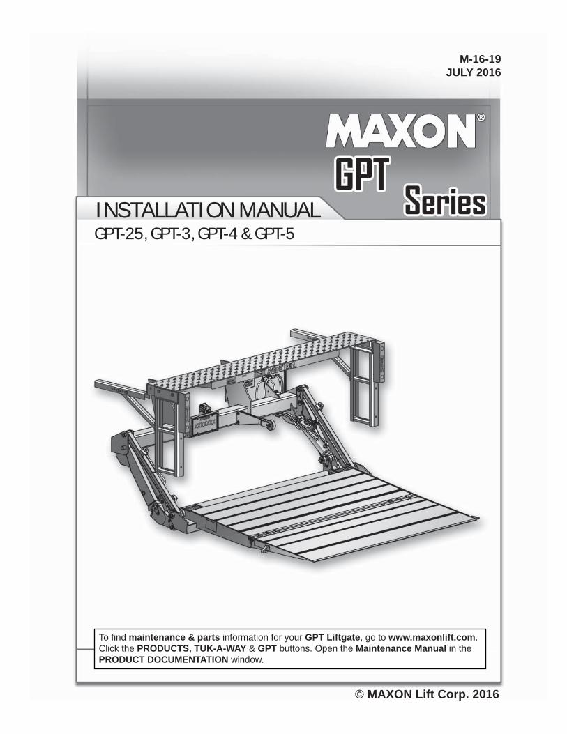
© MAXON Lift Corp. 2016 INSTALLATION MANUAL GPT-25, GPT-3, GPT-4 & GPT-5 M-16-19 JULY 2016 To find maintenance & parts information for your GPT Liftgate, go to www.maxonlift.com. Click the PRODUCTS, TUK-A-WAY & GPT buttons. Open the Maintenance Manual in the PRODUCT DOCUMENTATION window.
Transcript of INSTALLATION MANUAL - MAXON Lift MANUAL GPT-25, GPT-3, GPT-4 & GPT-5 M-16-19 JULY 2016 To fi nd...
© MAXON Lift Corp. 2016
INSTALL ATION MANUALGPT-25, GPT-3, GPT-4 & GPT-5
M-16-19JULY 2016
To fi nd maintenance & parts information for your GPT Liftgate, go to www.maxonlift.com. Click the PRODUCTS, TUK-A-WAY & GPT buttons. Open the Maintenance Manual in the PRODUCT DOCUMENTATION window.

TABLE OF CONTENTS
SUMMARY OF CHANGES: M-16-19 .................................................................................... 4
WARNINGS ........................................................................................................................... 5
SAFETY INSTRUCTIONS .................................................................................................... 6
NOTICE ................................................................................................................................. 6
STANDARD LIFTGATE COMPONENTS .............................................................................. 7
GPT-SERIES INSTALLATION PARTS BOX .......................................................................... 8
GPT-SERIES MANUALS & DECALS .................................................................................... 9
VEHICLE REQUIREMENTS ............................................................................................... 10
CENTER OF MASS ............................................................................................................. 13
STEP 1 - ATTACH EXTENSION PLATE TO VEHICLE ....................................................... 15
BOLT EXTENSION PLATE................................................................................... 15
WELD EXTENSION PLATE (ALTERNATE METHOD) ......................................... 18
STEP 2 - WELD LIFTGATE TO VEHICLE ......................................................................... 20
STEP 3 - ATTACH OPTIONAL BATTERY BOX & FRAME TO VEHICLE (IF EQUIPPED) . 24
STEP 4 - RUN POWER CABLE .......................................................................................... 32
STEP 5 - CONNECT POWER CABLE ................................................................................ 34
STEP 6 - INSTALL CONTROL SWITCH ............................................................................. 36
STEP 7 - ADDING HYDRAULIC FLUID .............................................................................. 38
STEP 8 - CONNECT POWER CABLE TO BATTERY ......................................................... 40
STEP 9 - REMOVE LOCKING ANGLES & KNUCKLE BOLTS, CHECK FOR
INTERFERENCE ................................................................................................. 41
STEP 10 - INSTALL OPENER, LICENSE PLATE BRACKET, & ICC BUMPER (IF
EQUIPPED) ....................................................................................................... 46
STEP 11 - ADJUST PLATFORM (IF REQUIRED) ............................................................... 50
STEP 12 - FINISH WELDING LIFTGATE TO VEHICLE ..................................................... 52
STEP 13 - BOLT STEPS TO EXTENSION PLATE ............................................................ 53
STEP 14 - LUBE GREASE FITTINGS (AS NEEDED) ........................................................ 57
APPLY DECALS ................................................................................................................. 58
DECALS & PLATES ........................................................................................................... 60
TOUCHUP PAINTED OR GALVANIZED FINISH ............................................................... 61
SYSTEM DIAGRAMS ......................................................................................................... 62
PUMP & MOTOR SOLENOID SWITCH OPERATION ........................................................ 62
HYDRAULIC SCHEMATIC (POWER DOWN) .................................................................... 63
ELECTRICAL SCHEMATIC (POWER DOWN) ................................................................... 64
OPTIONS ............................................................................................................................ 65
OPTIONAL LIFTGATE COMPONENTS .............................................................................. 65
1192
1 Sl
auso
n A
ve.
Sant
a Fe
Spr
ings
, CA
. 90
670
(80
0) 2
27-4
116
FA
X (
888)
771
-771
3
4
PAGE DESCRIPTION OF CHANGE
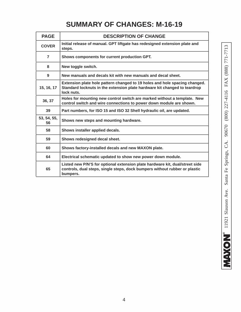
COVER Initial release of manual. GPT liftgate has redesigned extension plate and steps.
7 Shows components for current production GPT.
8 New toggle switch.
9 New manuals and decals kit with new manuals and decal sheet.
15, 16, 17Extension plate hole pattern changed to 19 holes and hole spacing changed. Standard locknuts in the extension plate hardware kit changed to teardrop lock nuts.
36, 37 Holes for mounting new control switch are marked without a template. New control switch and wire connections to power down module are shown.
39 Part numbers, for ISO 15 and ISO 32 Shell hydraulic oil, are updated.
53, 54, 55, 56 Shows new steps and mounting hardware.
58 Shows installer applied decals.
59 Shows redesigned decal sheet.
60 Shows factory-installed decals and new MAXON plate.
64 Electrical schematic updated to show new power down module.
65Listed new P/N’S for optional extension plate hardware kit, dual/street side controls, dual steps, single steps, dock bumpers without rubber or plastic bumpers.
SUMMARY OF CHANGES: M-16-19
1192
1 Sl
auso
n A
ve.
Sant
a Fe
Spr
ings
, CA
. 90
670
(80
0) 2
27-4
116
FA
X (
888)
771
-771
3
5
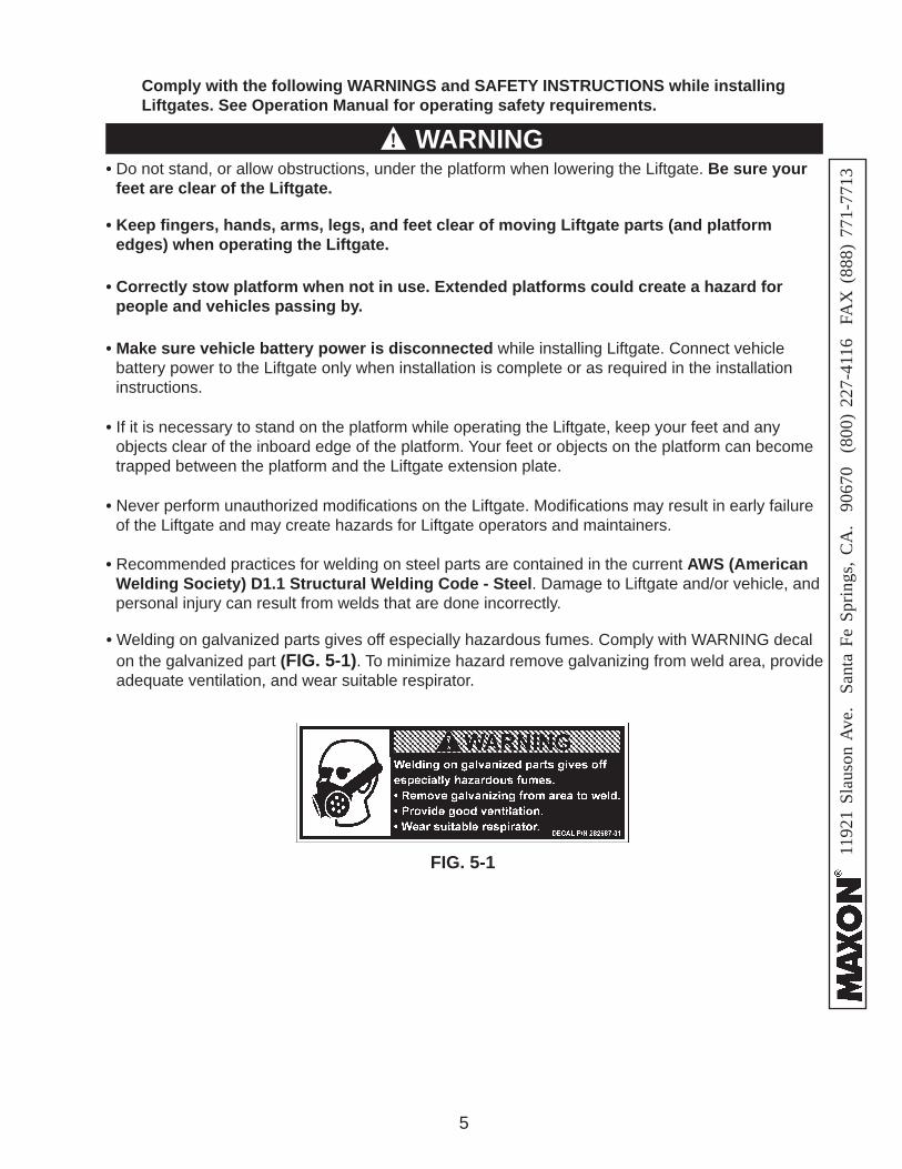
• Do not stand, or allow obstructions, under the platform when lowering the Liftgate. Be sure your feet are clear of the Liftgate.
• Keep fi ngers, hands, arms, legs, and feet clear of moving Liftgate parts (and platform edges) when operating the Liftgate.
• Make sure vehicle battery power is disconnected while installing Liftgate. Connect vehicle battery power to the Liftgate only when installation is complete or as required in the installation instructions.
Comply with the following WARNINGS and SAFETY INSTRUCTIONS while installing Liftgates. See Operation Manual for operating safety requirements.
• If it is necessary to stand on the platform while operating the Liftgate, keep your feet and any objects clear of the inboard edge of the platform. Your feet or objects on the platform can become trapped between the platform and the Liftgate extension plate.
• Never perform unauthorized modifi cations on the Liftgate. Modifi cations may result in early failure of the Liftgate and may create hazards for Liftgate operators and maintainers.
• Correctly stow platform when not in use. Extended platforms could create a hazard for people and vehicles passing by.
WARNING
• Recommended practices for welding on steel parts are contained in the current AWS (American Welding Society) D1.1 Structural Welding Code - Steel. Damage to Liftgate and/or vehicle, and personal injury can result from welds that are done incorrectly.
!WARNINGS
• Welding on galvanized parts gives off especially hazardous fumes. Comply with WARNING decal on the galvanized part (FIG. 5-1). To minimize hazard remove galvanizing from weld area, provide adequate ventilation, and wear suitable respirator.
FIG. 5-1
1192
1 Sl
auso
n A
ve.
Sant
a Fe
Spr
ings
, CA
. 90
670
(80
0) 2
27-4
116
FA
X (
888)
771
-771
3
6
NOTICE NOTICE• Maxon Lift is responsible for the instructions to correctly install MAXON Liftgates on
trucks or trailers only.
• Liftgate installers, not Maxon Lift, are responsible for reviewing and complying with all applicable Federal, State, and Local regulations pertaining to the trailer or truck.
SAFETY INSTRUCTIONSSAFETY INSTRUCTIONS
• Comply with all WARNING and instruction decals attached to the Liftgate.
• Keep decals clean and legible. If decals are illegible or missing, replace them. Free replacement decals are available from Maxon Customer Service.
• Consider the safety and location of bystanders and location of nearby objects when operating the Liftgate. Stand to one side of the platform while operating the Liftgate.
• Wear appropriate safety equipment such as protective eyeglasses, faceshield and clothing while performing maintenance on the Liftgate and handling the battery. Debris from drilling and contact with battery acid may injure unprotected eyes and skin.
• Do not allow untrained persons to operate the Liftgate.
• Be careful working by an automotive type battery. Make sure the work area is well ventilated and there are no fl ames or sparks near the battery. Never lay objects on the battery that can short the terminals together. If battery acid gets in your eyes, immediately seek fi rst aid. If acid gets on your skin, immediately wash it off with soap and water.
• If an emergency situation arises (vehicle or Liftgate) while operating the Liftgate, release the con-trol switch to stop the Liftgate.
• Read and understand the instructions in this Installation Manual before installing Liftgate.
• Before operating the Liftgate, read and understand the operating instructions in Operation Manual.
• A correctly installed Liftgate operates smoothly and reasonably quiet. The only noticeable noise during operation comes from the power unit while the platform is raised and lowered. Listen for scraping, grating and binding noises and correct the problem before continuing to operate Liftgate.
• Installers of the liftgate should ensure that all trucks and trailers are equipped with grab handles as needed.
1192
1 Sl
auso
n A
ve.
Sant
a Fe
Spr
ings
, CA
. 90
670
(80
0) 2
27-4
116
FA
X (
888)
771
-771
3
7
STANDARD LIFTGATE COMPONENTSCAUTION
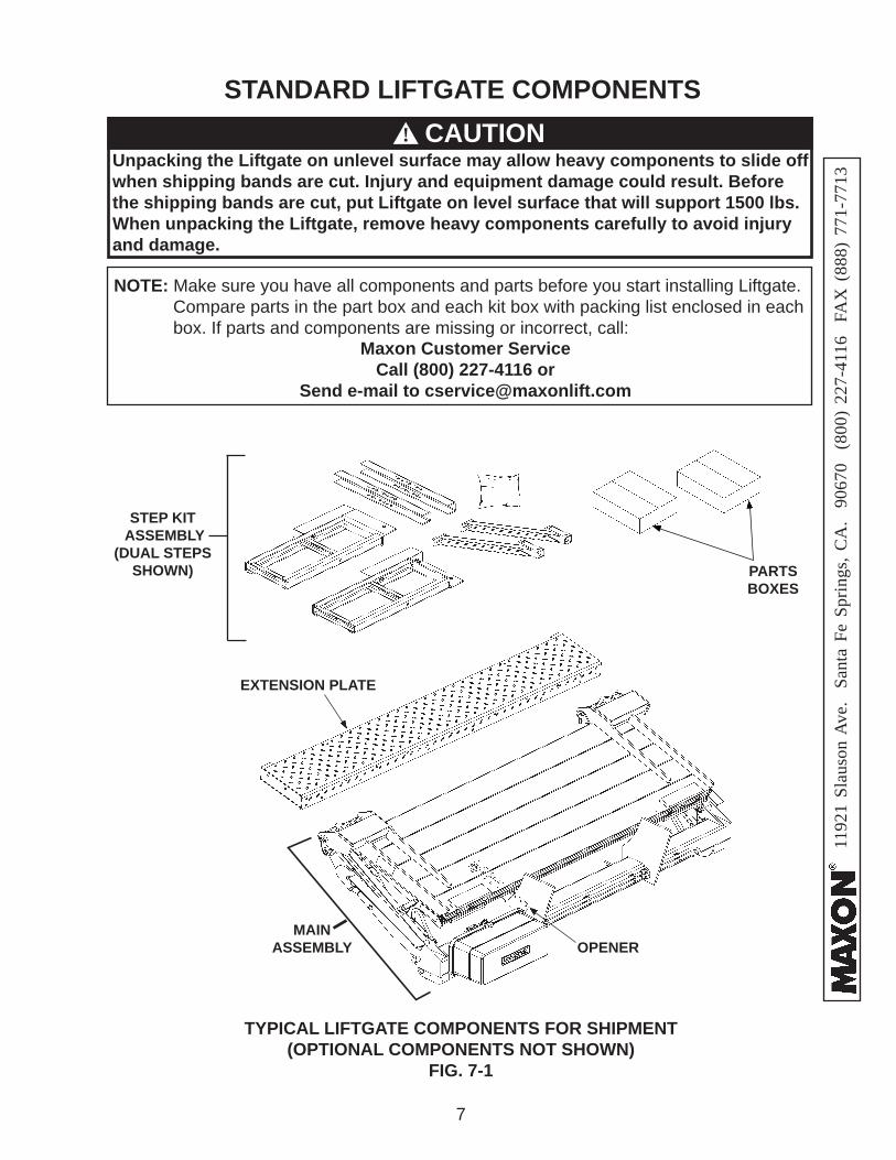
TYPICAL LIFTGATE COMPONENTS FOR SHIPMENT(OPTIONAL COMPONENTS NOT SHOWN)
FIG. 7-1
!
NOTE: Make sure you have all components and parts before you start installing Liftgate. Compare parts in the part box and each kit box with packing list enclosed in each box. If parts and components are missing or incorrect, call:
Maxon Customer ServiceCall (800) 227-4116 or
Send e-mail to [email protected]
EXTENSION PLATE
MAIN ASSEMBLY
Unpacking the Liftgate on unlevel surface may allow heavy components to slide off when shipping bands are cut. Injury and equipment damage could result. Before the shipping bands are cut, put Liftgate on level surface that will support 1500 lbs. When unpacking the Liftgate, remove heavy components carefully to avoid injury and damage.
PARTS BOXES
OPENER
STEP KIT ASSEMBLY
(DUAL STEPS SHOWN)
1192
1 Sl
auso
n A
ve.
Sant
a Fe
Spr
ings
, CA
. 90
670
(80
0) 2
27-4
116
FA
X (
888)
771
-771
3
8
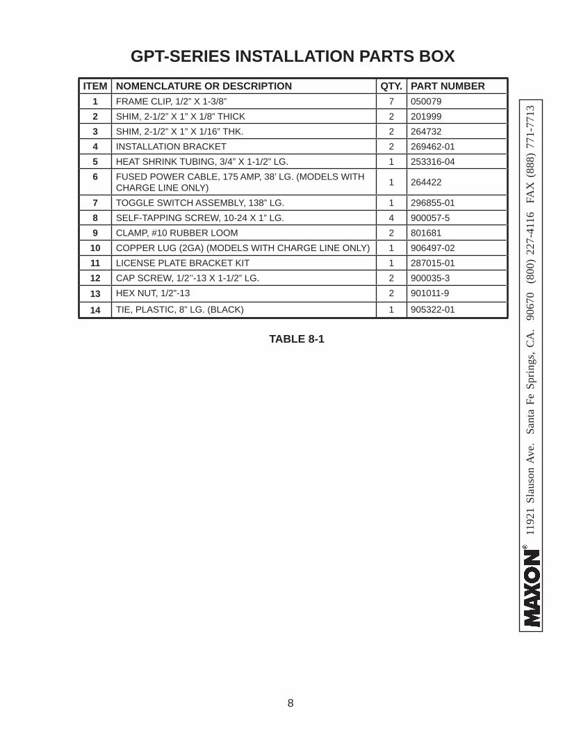
GPT-SERIES INSTALLATION PARTS BOX
TABLE 8-1
ITEM NOMENCLATURE OR DESCRIPTION QTY. PART NUMBER1 FRAME CLIP, 1/2” X 1-3/8” 7 0500792 SHIM, 2-1/2” X 1” X 1/8” THICK 2 2019993 SHIM, 2-1/2” X 1” X 1/16” THK. 2 2647324 INSTALLATION BRACKET 2 269462-015 HEAT SHRINK TUBING, 3/4” X 1-1/2” LG. 1 253316-046 FUSED POWER CABLE, 175 AMP, 38’ LG. (MODELS WITH
CHARGE LINE ONLY) 1 264422
7 TOGGLE SWITCH ASSEMBLY, 138” LG. 1 296855-018 SELF-TAPPING SCREW, 10-24 X 1” LG. 4 900057-59 CLAMP, #10 RUBBER LOOM 2 801681
10 COPPER LUG (2GA) (MODELS WITH CHARGE LINE ONLY) 1 906497-0211 LICENSE PLATE BRACKET KIT 1 287015-0112 CAP SCREW, 1/2’’-13 X 1-1/2” LG. 2 900035-3
13 HEX NUT, 1/2”-13 2 901011-9
14 TIE, PLASTIC, 8” LG. (BLACK) 1 905322-01
1192
1 Sl
auso
n A
ve.
Sant
a Fe
Spr
ings
, CA
. 90
670
(80
0) 2
27-4
116
FA
X (
888)
771
-771
3
9
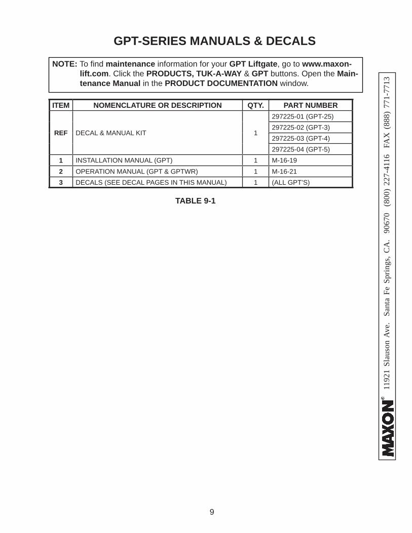
GPT-SERIES MANUALS & DECALS
ITEM NOMENCLATURE OR DESCRIPTION QTY. PART NUMBER
REF DECAL & MANUAL KIT 1
297225-01 (GPT-25)297225-02 (GPT-3)297225-03 (GPT-4)297225-04 (GPT-5)
1 INSTALLATION MANUAL (GPT) 1 M-16-192 OPERATION MANUAL (GPT & GPTWR) 1 M-16-213 DECALS (SEE DECAL PAGES IN THIS MANUAL) 1 (ALL GPT’S)
TABLE 9-1
NOTE: To fi nd maintenance information for your GPT Liftgate, go to www.maxon-lift.com. Click the PRODUCTS, TUK-A-WAY & GPT buttons. Open the Main-tenance Manual in the PRODUCT DOCUMENTATION window.
1192
1 Sl
auso
n A
ve.
Sant
a Fe
Spr
ings
, CA
. 90
670
(80
0) 2
27-4
116
FA
X (
888)
771
-771
3
10
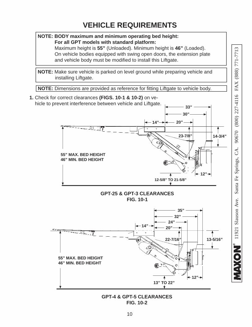
VEHICLE REQUIREMENTS
1. Check for correct clearances (FIGS. 10-1 & 10-2) on ve-hicle to prevent interference between vehicle and Liftgate.
GPT-25 & GPT-3 CLEARANCESFIG. 10-1
12-5/8” TO 21-5/8”
55” MAX. BED HEIGHT46” MIN. BED HEIGHT
NOTE: Make sure vehicle is parked on level ground while preparing vehicle and installing Liftgate.
NOTE: BODY maximum and minimum operating bed height: For all GPT models with standard platform: Maximum height is 55” (Unloaded). Minimum height is 46” (Loaded). On vehicle bodies equipped with swing open doors, the extension plate
and vehicle body must be modifi ed to install this Liftgate.
NOTE: Dimensions are provided as reference for fi tting Liftgate to vehicle body.
14-3/4”
20”14”
33”30”
12”
GPT-4 & GPT-5 CLEARANCESFIG. 10-2
13” TO 22”
55” MAX. BED HEIGHT46” MIN. BED HEIGHT
13-5/16”
24”14”
35”32”
12”
23-7/8”
22-7/16”
20”
1192
1 Sl
auso
n A
ve.
Sant
a Fe
Spr
ings
, CA
. 90
670
(80
0) 2
27-4
116
FA
X (
888)
771
-771
3
11
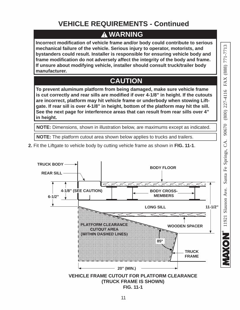
2. Fit the Liftgate to vehicle body by cutting vehicle frame as shown in FIG. 11-1.
VEHICLE REQUIREMENTS - Continued
VEHICLE FRAME CUTOUT FOR PLATFORM CLEARANCE (TRUCK FRAME IS SHOWN)
FIG. 11-1
20” (MIN.)
6-1/2”
WOODEN SPACER
BODY FLOOR
To prevent aluminum platform from being damaged, make sure vehicle frame is cut correctly and rear sills are modifi ed if over 4-1/8” in height. If the cutouts are incorrect, platform may hit vehicle frame or underbody when stowing Lift-gate. If rear sill is over 4-1/8” in height, bottom of the platform may hit the sill.See the next page for interference areas that can result from rear sills over 4”in height.
CAUTION
BODY CROSS-MEMBERS
LONG SILL
TRUCKFRAME
PLATFORM CLEARANCE CUTOUT AREA
(WITHIN DASHED LINES)
TRUCK BODY
4-1/8” (SEE CAUTION)
REAR SILL
NOTE: The platform cutout area shown below applies to trucks and trailers.
NOTE: Dimensions, shown in illustration below, are maximums except as indicated.
11-1/2”
85º
Incorrect modifi cation of vehicle frame and/or body could contribute to serious mechanical failure of the vehicle. Serious injury to operator, motorists, and bystanders could result. Installer is responsible for ensuring vehicle body and frame modifi cation do not adversely affect the integrity of the body and frame. If unsure about modifying vehicle, installer should consult truck/trailer body manufacturer.
WARNING!
1192
1 Sl
auso
n A
ve.
Sant
a Fe
Spr
ings
, CA
. 90
670
(80
0) 2
27-4
116
FA
X (
888)
771
-771
3
12
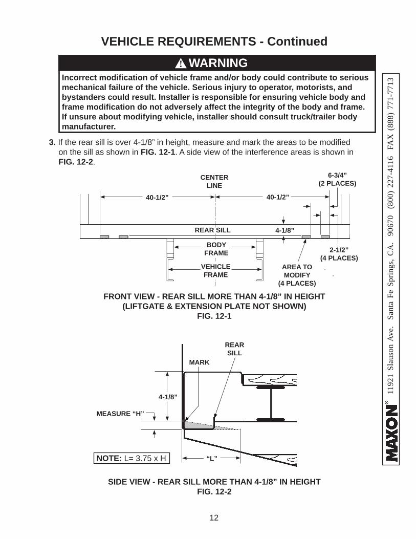
VEHICLE REQUIREMENTS - Continued
FRONT VIEW - REAR SILL MORE THAN 4-1/8” IN HEIGHT(LIFTGATE & EXTENSION PLATE NOT SHOWN)
FIG. 12-1
CENTERLINE
40-1/2”
3. If the rear sill is over 4-1/8” in height, measure and mark the areas to be modifi ed on the sill as shown in FIG. 12-1. A side view of the interference areas is shown in FIG. 12-2.
2-1/2”(4 PLACES)
VEHICLE FRAME
BODY FRAME
40-1/2”
SIDE VIEW - REAR SILL MORE THAN 4-1/8” IN HEIGHTFIG. 12-2
REAR SILL
6-3/4”(2 PLACES)
4-1/8”
REARSILL
4-1/8”
MEASURE “H”
MARK
“L”NOTE: L= 3.75 x H
AREA TO MODIFY
(4 PLACES)
Incorrect modifi cation of vehicle frame and/or body could contribute to serious mechanical failure of the vehicle. Serious injury to operator, motorists, and bystanders could result. Installer is responsible for ensuring vehicle body and frame modifi cation do not adversely affect the integrity of the body and frame. If unsure about modifying vehicle, installer should consult truck/trailer body manufacturer.
WARNING!
1192
1 Sl
auso
n A
ve.
Sant
a Fe
Spr
ings
, CA
. 90
670
(80
0) 2
27-4
116
FA
X (
888)
771
-771
3
13
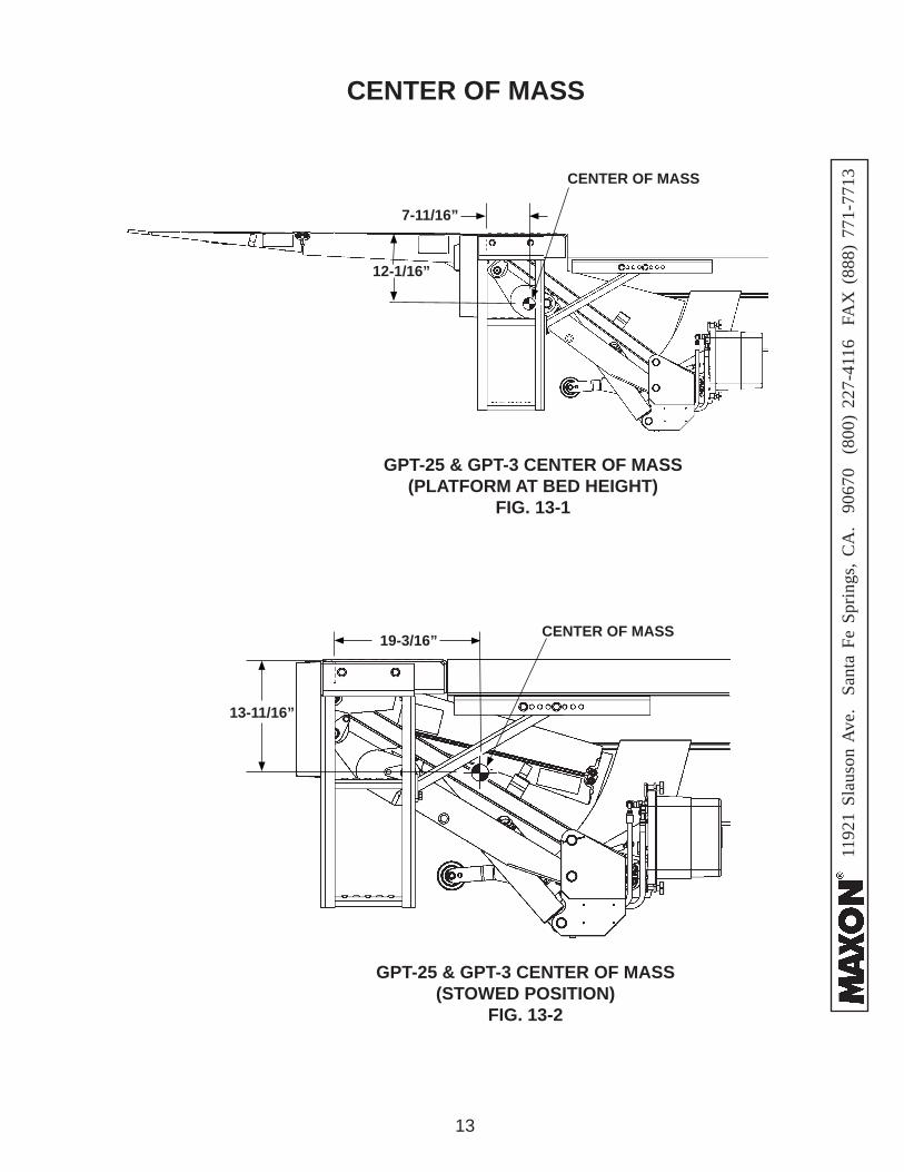
CENTER OF MASS
GPT-25 & GPT-3 CENTER OF MASS(STOWED POSITION)
FIG. 13-2
GPT-25 & GPT-3 CENTER OF MASS(PLATFORM AT BED HEIGHT)
FIG. 13-1
12-1/16”
CENTER OF MASS
7-11/16”
13-11/16”
19-3/16” CENTER OF MASS

1192
1 Sl
auso
n A
ve.
Sant
a Fe
Spr
ings
, CA
. 90
670
(80
0) 2
27-4
116
FA
X (
888)
771
-771
3
14
CENTER OF MASS - Continued
GPT-4 & GPT-5 CENTER OF MASS(STOWED POSITION)
FIG. 14-2
GPT-4 & GPT-5 CENTER OF MASS(PLATFORM AT BED HEIGHT)
FIG. 14-1
10-7/8”
CENTER OF MASS
13-11/16”
20-5/16” CENTER OF MASS
7-11/16”
1192
1 Sl
auso
n A
ve.
Sant
a Fe
Spr
ings
, CA
. 90
670
(80
0) 2
27-4
116
FA
X (
888)
771
-771
3
15
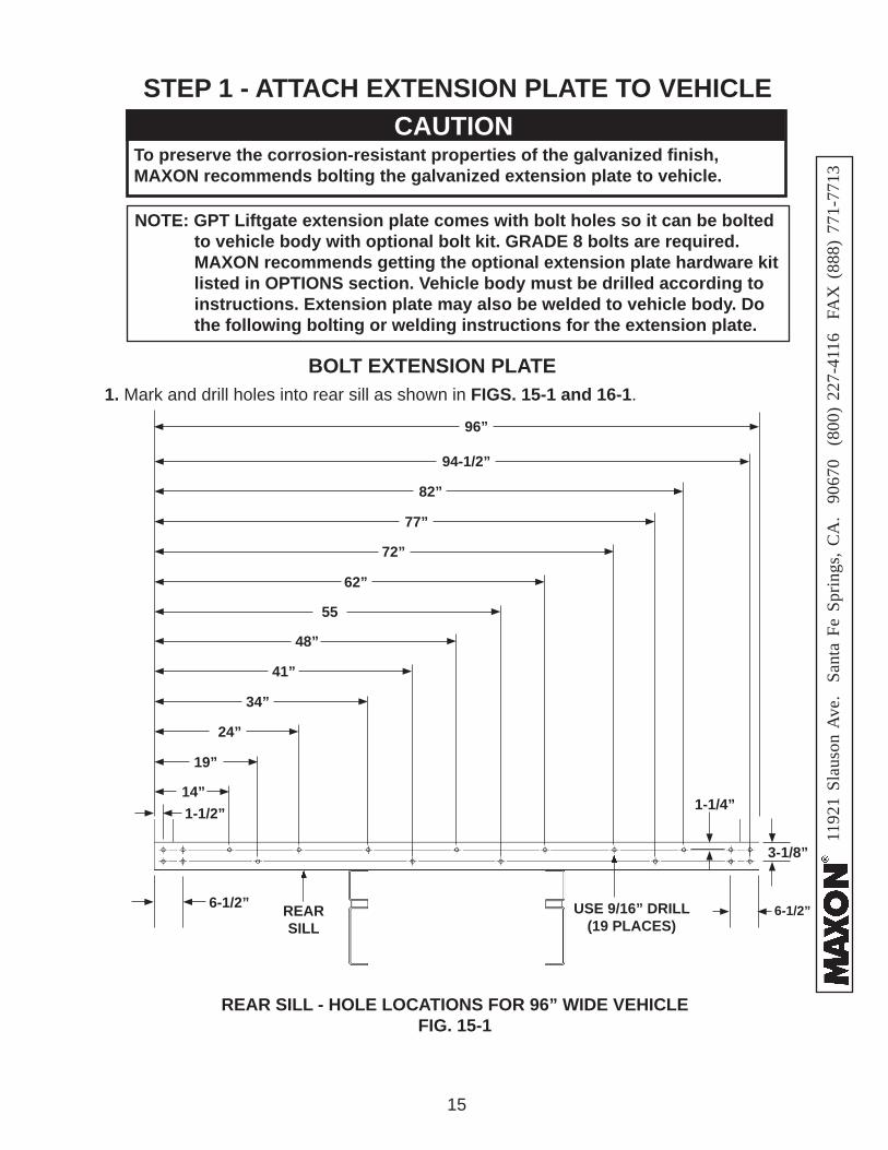
STEP 1 - ATTACH EXTENSION PLATE TO VEHICLE
1. Mark and drill holes into rear sill as shown in FIGS. 15-1 and 16-1.
REAR SILL - HOLE LOCATIONS FOR 96” WIDE VEHICLEFIG. 15-1
USE 9/16” DRILL(19 PLACES)
1-1/4”
3-1/8”
REAR SILL
1-1/2”
19”
24”
14”
34”
41”
48”
55
62”
72”
77”
82”
94-1/2”
96”
BOLT EXTENSION PLATE
NOTE: GPT Liftgate extension plate comes with bolt holes so it can be bolted to vehicle body with optional bolt kit. GRADE 8 bolts are required. MAXON recommends getting the optional extension plate hardware kit listed in OPTIONS section. Vehicle body must be drilled according to instructions. Extension plate may also be welded to vehicle body. Do the following bolting or welding instructions for the extension plate.
CAUTIONTo preserve the corrosion-resistant properties of the galvanized fi nish,MAXON recommends bolting the galvanized extension plate to vehicle.
CAUTION
6-1/2” 6-1/2”
1192
1 Sl
auso
n A
ve.
Sant
a Fe
Spr
ings
, CA
. 90
670
(80
0) 2
27-4
116
FA
X (
888)
771
-771
3
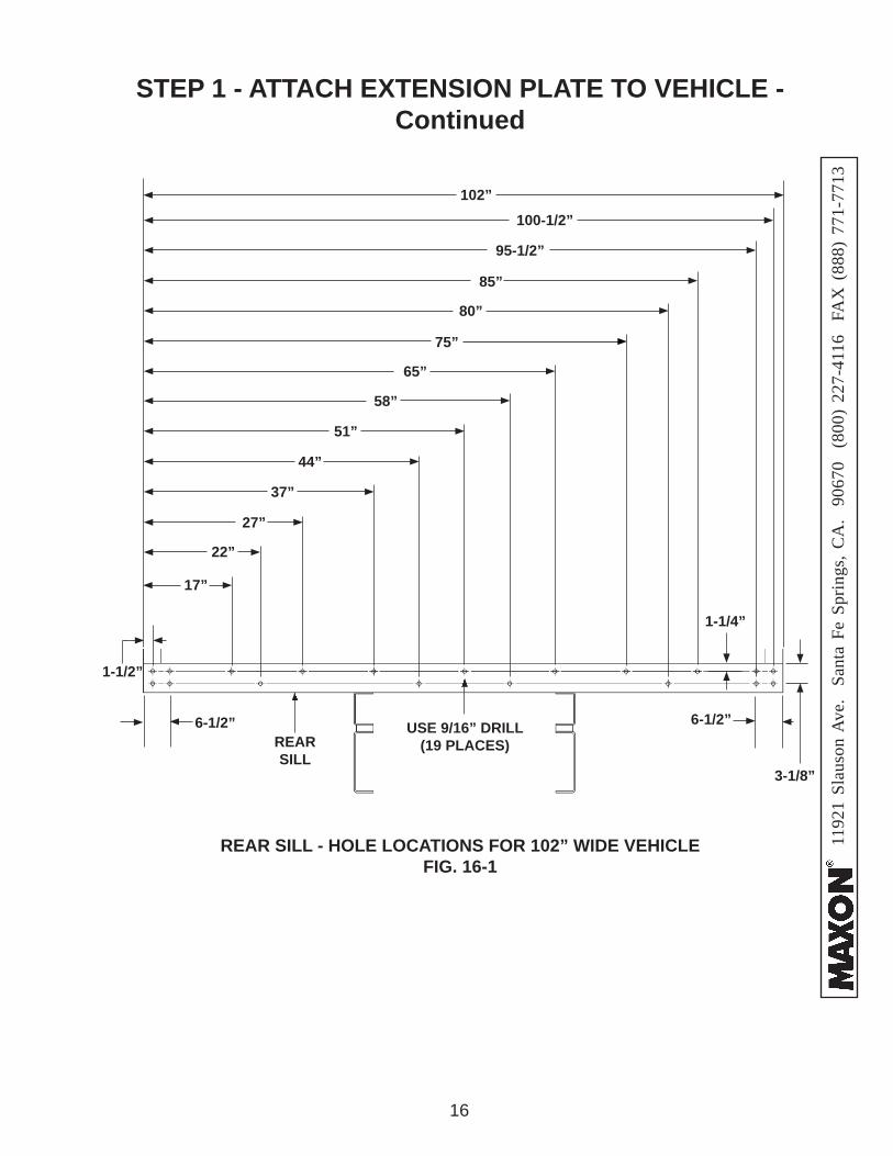
16
REAR SILL - HOLE LOCATIONS FOR 102” WIDE VEHICLEFIG. 16-1
1-1/4”
1-1/2”
27”
37”
44”
51”
58”
65”
75”
80”
85”
95-1/2”
100-1/2”102”
22”
17”
STEP 1 - ATTACH EXTENSION PLATE TO VEHICLE - Continued
REAR SILL
USE 9/16” DRILL(19 PLACES)
6-1/2” 6-1/2”
3-1/8”
1192
1 Sl
auso
n A
ve.
Sant
a Fe
Spr
ings
, CA
. 90
670
(80
0) 2
27-4
116
FA
X (
888)
771
-771
3
17
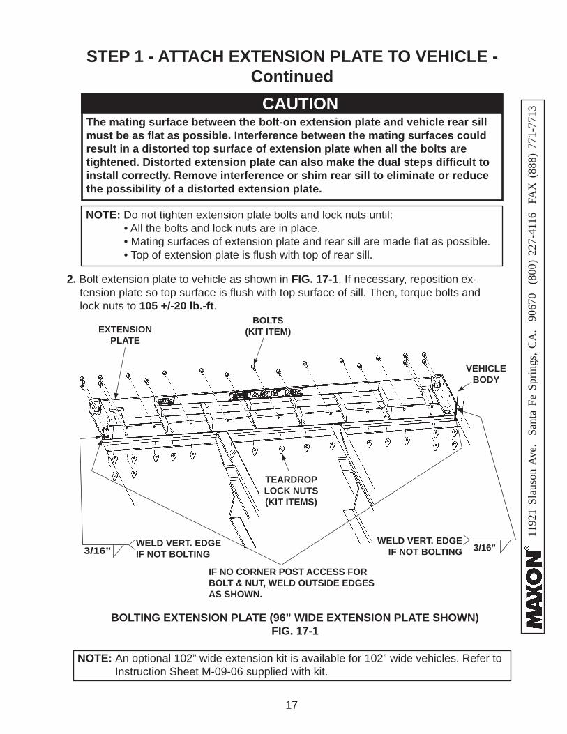
2. Bolt extension plate to vehicle as shown in FIG. 17-1. If necessary, reposition ex-tension plate so top surface is fl ush with top surface of sill. Then, torque bolts and lock nuts to 105 +/-20 lb.-ft.
NOTE: Do not tighten extension plate bolts and lock nuts until: • All the bolts and lock nuts are in place. • Mating surfaces of extension plate and rear sill are made fl at as possible. • Top of extension plate is fl ush with top of rear sill.
STEP 1 - ATTACH EXTENSION PLATE TO VEHICLE - ContinuedCAUTION
The mating surface between the bolt-on extension plate and vehicle rear sill must be as fl at as possible. Interference between the mating surfaces could result in a distorted top surface of extension plate when all the bolts are tightened. Distorted extension plate can also make the dual steps diffi cult to install correctly. Remove interference or shim rear sill to eliminate or reduce the possibility of a distorted extension plate.
CAUTION
BOLTING EXTENSION PLATE (96” WIDE EXTENSION PLATE SHOWN)FIG. 17-1
BOLTS(KIT ITEM)EXTENSION
PLATE
VEHICLE BODY
NOTE: An optional 102” wide extension kit is available for 102” wide vehicles. Refer to Instruction Sheet M-09-06 supplied with kit.
TEARDROP LOCK NUTS(KIT ITEMS)
IF NO CORNER POST ACCESS FORBOLT & NUT, WELD OUTSIDE EDGESAS SHOWN.
3/16”WELD VERT. EDGEIF NOT BOLTING
WELD VERT. EDGEIF NOT BOLTING 3/16”
1192
1 Sl
auso
n A
ve.
Sant
a Fe
Spr
ings
, CA
. 90
670
(80
0) 2
27-4
116
FA
X (
888)
771
-771
3
18
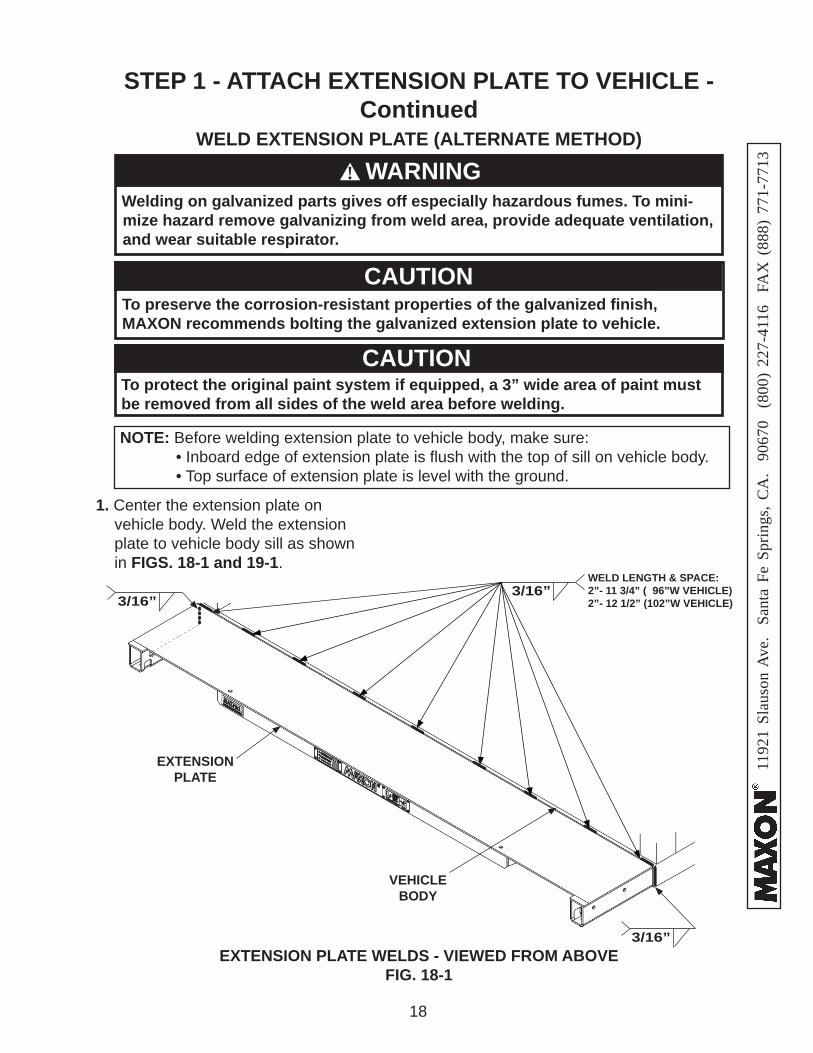
WELD EXTENSION PLATE (ALTERNATE METHOD)
STEP 1 - ATTACH EXTENSION PLATE TO VEHICLE - Continued
NOTE: Before welding extension plate to vehicle body, make sure: • Inboard edge of extension plate is fl ush with the top of sill on vehicle body. • Top surface of extension plate is level with the ground.
1. Center the extension plate on vehicle body. Weld the extension plate to vehicle body sill as shown in FIGS. 18-1 and 19-1.
To protect the original paint system if equipped, a 3” wide area of paint must be removed from all sides of the weld area before welding.
CAUTION
`
Welding on galvanized parts gives off especially hazardous fumes. To mini-mize hazard remove galvanizing from weld area, provide adequate ventilation, and wear suitable respirator.
WARNING!
EXTENSION PLATE WELDS - VIEWED FROM ABOVEFIG. 18-1
3/16”3/16”
EXTENSION PLATE
VEHICLE BODY
3/16”
WELD LENGTH & SPACE:2”- 11 3/4” ( 96”W VEHICLE)2”- 12 1/2” (102”W VEHICLE)
To preserve the corrosion-resistant properties of the galvanized fi nish,MAXON recommends bolting the galvanized extension plate to vehicle.
CAUTION
1192
1 Sl
auso
n A
ve.
Sant
a Fe
Spr
ings
, CA
. 90
670
(80
0) 2
27-4
116
FA
X (
888)
771
-771
3
19
EXTENSION PLATE
BRACKET(2 PLACES)
BOLTING ON INSTALLATION BRACKETSFIG. 19-2
CAP SCREW1/2”-13 X 1-1/2” LG.
(2 PLACES)
HEX NUT1/2”-13
(2 PLACES)
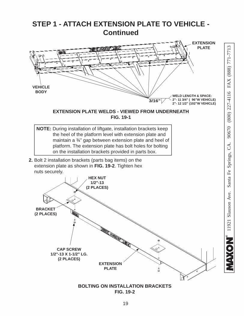
2. Bolt 2 installation brackets (parts bag items) on the extension plate as shown in FIG. 19-2. Tighten hex nuts securely.
EXTENSION PLATE WELDS - VIEWED FROM UNDERNEATHFIG. 19-1
3/16”
EXTENSION PLATE
VEHICLE BODY
WELD LENGTH & SPACE:2”- 11 3/4” ( 96”W VEHICLE)2”- 12 1/2” (102”W VEHICLE)
NOTE: During installation of liftgate, installation brackets keep the heel of the platform level with extension plate and maintain a ¾” gap between extension plate and heel of platform. The extension plate has bolt holes for bolting on the installation brackets provided in parts box.
STEP 1 - ATTACH EXTENSION PLATE TO VEHICLE - Continued
1192
1 Sl
auso
n A
ve.
Sant
a Fe
Spr
ings
, CA
. 90
670
(80
0) 2
27-4
116
FA
X (
888)
771
-771
3
20
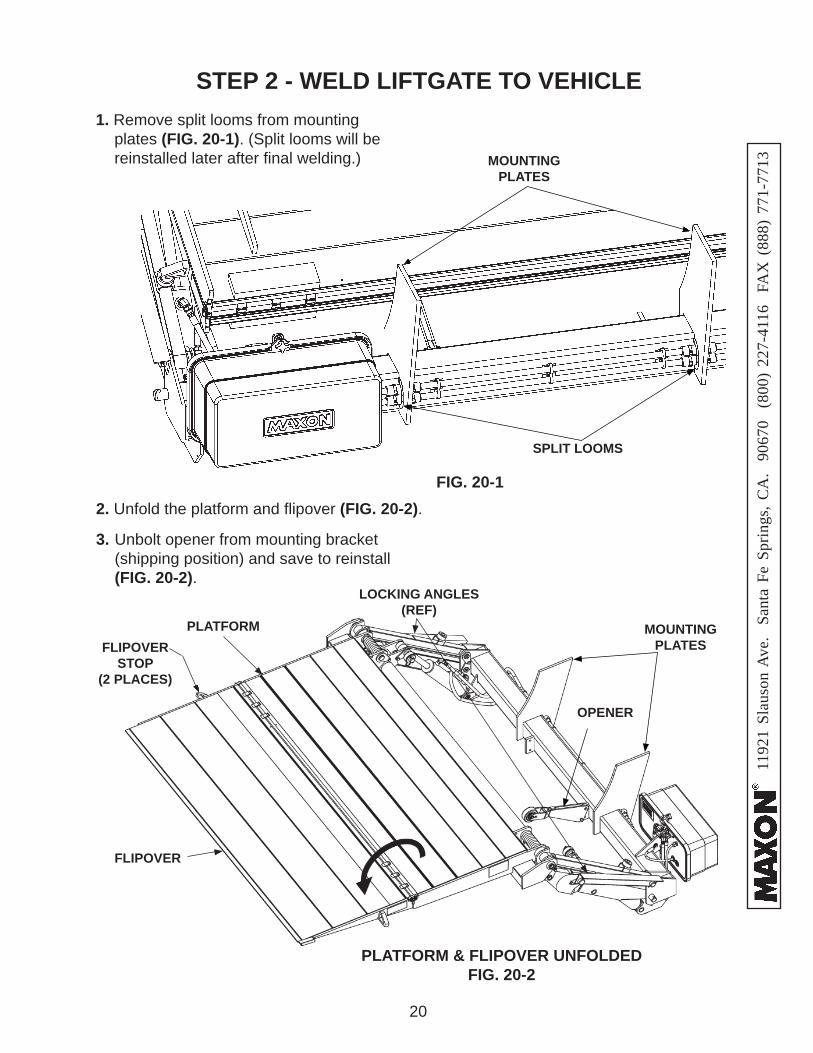
STEP 2 - WELD LIFTGATE TO VEHICLE 1. Remove split looms from mounting
plates (FIG. 20-1). (Split looms will be reinstalled later after fi nal welding.)
2. Unfold the platform and fl ipover (FIG. 20-2).
PLATFORM & FLIPOVER UNFOLDEDFIG. 20-2
FIG. 20-1
SPLIT LOOMS
MOUNTING PLATES
FLIPOVER
PLATFORM MOUNTING PLATES
LOCKING ANGLES (REF)
3. Unbolt opener from mounting bracket (shipping position) and save to reinstall (FIG. 20-2).
OPENER
FLIPOVERSTOP
(2 PLACES)
1192
1 Sl
auso
n A
ve.
Sant
a Fe
Spr
ings
, CA
. 90
670
(80
0) 2
27-4
116
FA
X (
888)
771
-771
3
21
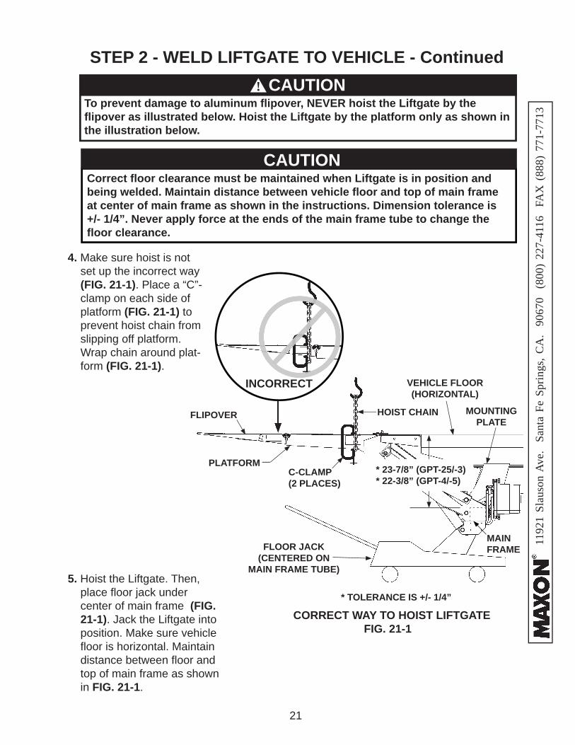
To prevent damage to aluminum fl ipover, NEVER hoist the Liftgate by the fl ipover as illustrated below. Hoist the Liftgate by the platform only as shown in the illustration below.
CAUTION
5. Hoist the Liftgate. Then, place fl oor jack under center of main frame (FIG. 21-1). Jack the Liftgate into position. Make sure vehicle fl oor is horizontal. Maintain distance between fl oor and top of main frame as shown in FIG. 21-1.
!
STEP 2 - WELD LIFTGATE TO VEHICLE - Continued
Correct fl oor clearance must be maintained when Liftgate is in position and being welded. Maintain distance between vehicle fl oor and top of main frame at center of main frame as shown in the instructions. Dimension tolerance is +/- 1/4”. Never apply force at the ends of the main frame tube to change the fl oor clearance.
CAUTION
FLOOR JACK(CENTERED ON
MAIN FRAME TUBE)
HOIST CHAIN
MAIN FRAME
VEHICLE FLOOR(HORIZONTAL)
MOUNTING PLATE
FLIPOVER
PLATFORMC-CLAMP(2 PLACES)
* TOLERANCE IS +/- 1/4”
CCORRECT WAY TO HOIST LIFTGATEFIG. 21-1
INCORRECT
* 23-7/8” (GPT-25/-3)* 22-3/8” (GPT-4/-5)
4. Make sure hoist is not set up the incorrect way (FIG. 21-1). Place a “C”-clamp on each side of platform (FIG. 21-1) to prevent hoist chain from slipping off platform. Wrap chain around plat-form (FIG. 21-1).
1192
1 Sl
auso
n A
ve.
Sant
a Fe
Spr
ings
, CA
. 90
670
(80
0) 2
27-4
116
FA
X (
888)
771
-771
3
22
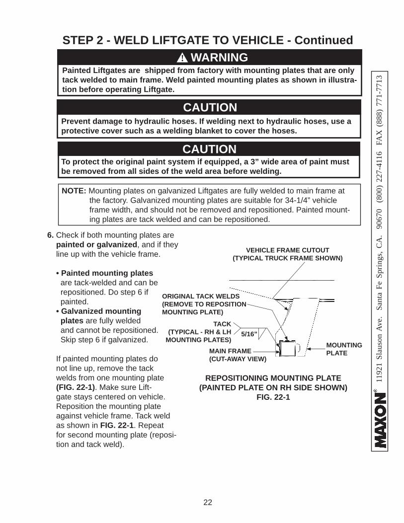
6. Check if both mounting plates are painted or galvanized, and if they line up with the vehicle frame.
• Painted mounting plates are tack-welded and can be repositioned. Do step 6 if painted. • Galvanized mounting plates are fully welded and cannot be repositioned. Skip step 6 if galvanized. If painted mounting plates do
not line up, remove the tack welds from one mounting plate (FIG. 22-1). Make sure Lift-gate stays centered on vehicle. Reposition the mounting plate against vehicle frame. Tack weld as shown in FIG. 22-1. Repeat for second mounting plate (reposi-tion and tack weld).
ORIGINAL TACK WELDS(REMOVE TO REPOSITION MOUNTING PLATE)
5/16”TACK
(TYPICAL - RH & LH MOUNTING PLATES)
REPOSITIONING MOUNTING PLATE (PAINTED PLATE ON RH SIDE SHOWN)
FIG. 22-1
MAIN FRAME(CUT-AWAY VIEW)
MOUNTINGPLATE
STEP 2 - WELD LIFTGATE TO VEHICLE - Continued
WARNING
Prevent damage to hydraulic hoses. If welding next to hydraulic hoses, use a protective cover such as a welding blanket to cover the hoses.
CAUTION
VEHICLE FRAME CUTOUT(TYPICAL TRUCK FRAME SHOWN)
To protect the original paint system if equipped, a 3” wide area of paint must be removed from all sides of the weld area before welding.
CAUTION
Painted Liftgates are shipped from factory with mounting plates that are only tack welded to main frame. Weld painted mounting plates as shown in illustra-tion before operating Liftgate.
WARNING!
NOTE: Mounting plates on galvanized Liftgates are fully welded to main frame at the factory. Galvanized mounting plates are suitable for 34-1/4” vehicle frame width, and should not be removed and repositioned. Painted mount-ing plates are tack welded and can be repositioned.
1192
1 Sl
auso
n A
ve.
Sant
a Fe
Spr
ings
, CA
. 90
670
(80
0) 2
27-4
116
FA
X (
888)
771
-771
3
23
STEP 2 - WELD LIFTGATE TO VEHICLE - Continued
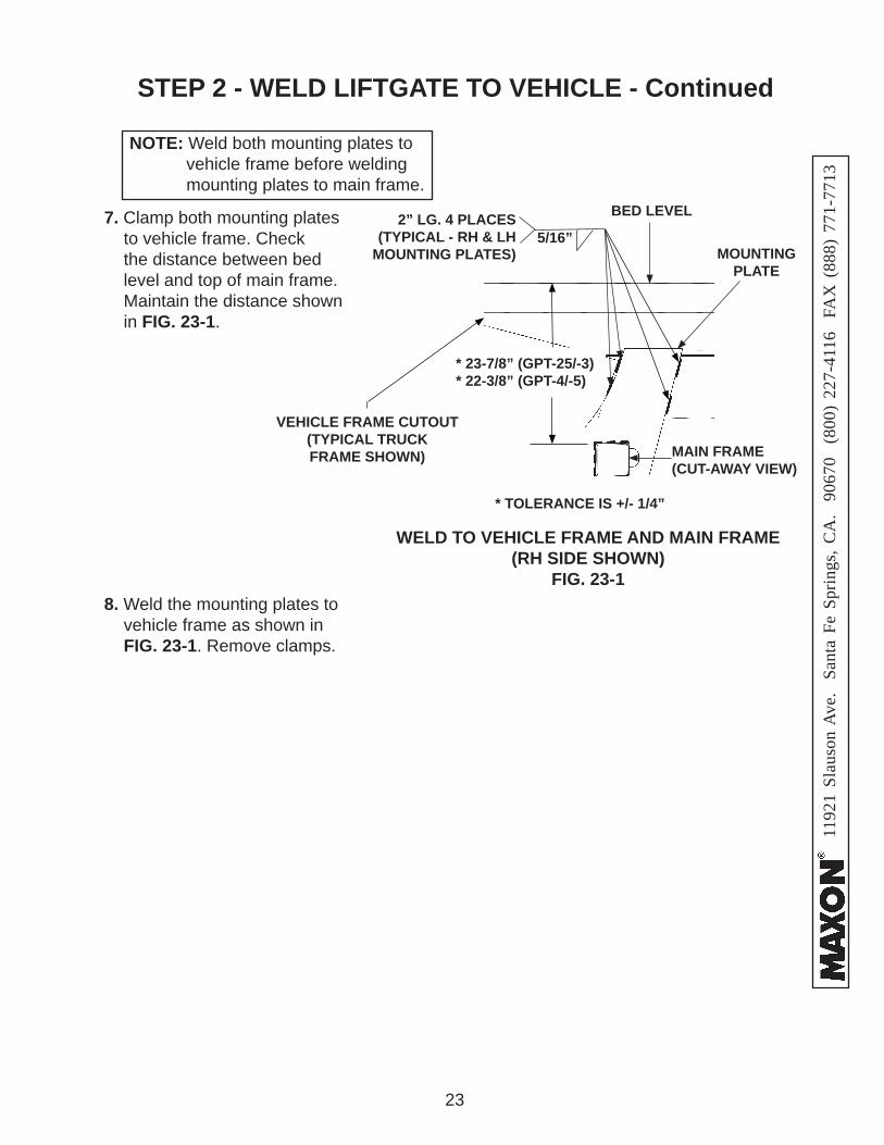
7. Clamp both mounting plates to vehicle frame. Check the distance between bed level and top of main frame. Maintain the distance shown in FIG. 23-1.
NOTE: Weld both mounting plates to vehicle frame before welding mounting plates to main frame.
VEHICLE FRAME CUTOUT(TYPICAL TRUCK FRAME SHOWN) MAIN FRAME
(CUT-AWAY VIEW)
MOUNTINGPLATE
BED LEVEL
WELD TO VEHICLE FRAME AND MAIN FRAME(RH SIDE SHOWN)
FIG. 23-1
2” LG. 4 PLACES(TYPICAL - RH & LH
MOUNTING PLATES)5/16”
8. Weld the mounting plates to vehicle frame as shown in FIG. 23-1. Remove clamps.
* TOLERANCE IS +/- 1/4”
* 23-7/8” (GPT-25/-3)* 22-3/8” (GPT-4/-5)
1192
1 Sl
auso
n A
ve.
Sant
a Fe
Spr
ings
, CA
. 90
670
(80
0) 2
27-4
116
FA
X (
888)
771
-771
3
24
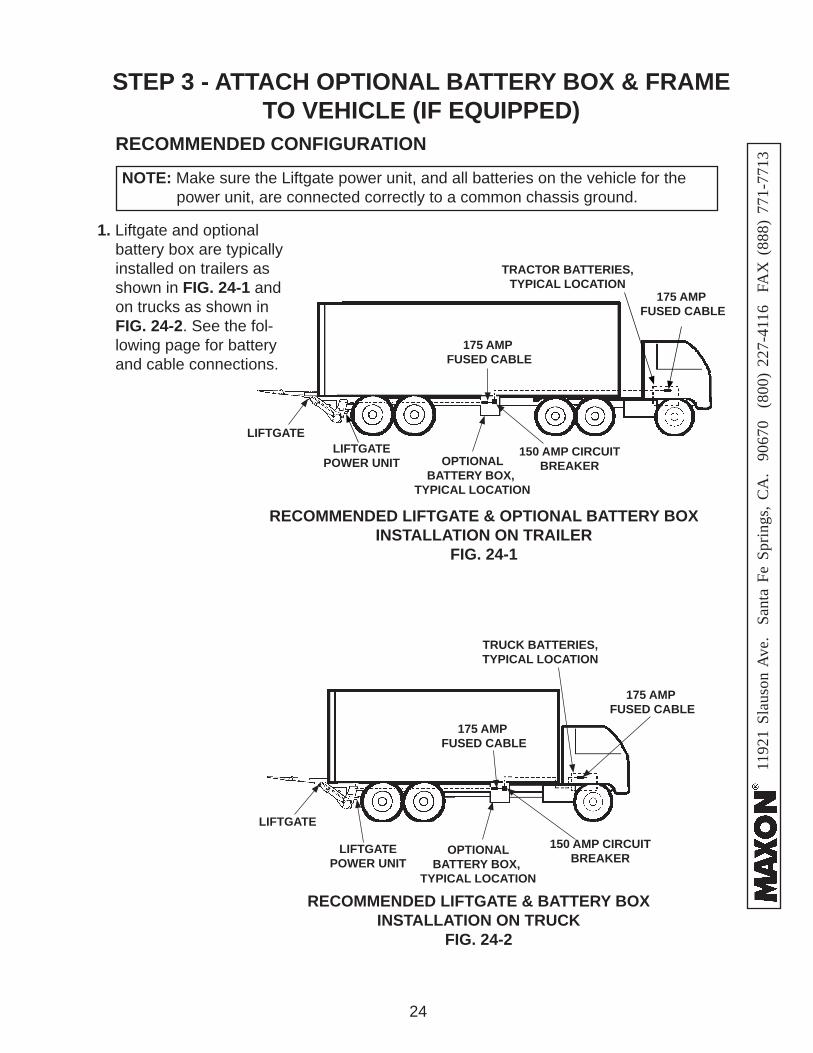
STEP 3 - ATTACH OPTIONAL BATTERY BOX & FRAME TO VEHICLE (IF EQUIPPED)
1. Liftgate and optional battery box are typically installed on trailers as shown in FIG. 24-1 and on trucks as shown in FIG. 24-2. See the fol-lowing page for battery and cable connections.
LIFTGATE
OPTIONAL BATTERY BOX,
TYPICAL LOCATION
RECOMMENDED LIFTGATE & OPTIONAL BATTERY BOX INSTALLATION ON TRAILER
FIG. 24-1
150 AMP CIRCUITBREAKER
175 AMP FUSED CABLE
TRACTOR BATTERIES,TYPICAL LOCATION
LIFTGATE
LIFTGATEPOWER UNIT
RECOMMENDED LIFTGATE & BATTERY BOX INSTALLATION ON TRUCK
FIG. 24-2
150 AMP CIRCUITBREAKER
RECOMMENDED CONFIGURATION
NOTE: Make sure the Liftgate power unit, and all batteries on the vehicle for the power unit, are connected correctly to a common chassis ground.
LIFTGATEPOWER UNIT
175 AMP FUSED CABLE
175 AMP FUSED CABLE
TRUCK BATTERIES,TYPICAL LOCATION
175 AMP FUSED CABLE
OPTIONAL BATTERY BOX,
TYPICAL LOCATION
1192
1 Sl
auso
n A
ve.
Sant
a Fe
Spr
ings
, CA
. 90
670
(80
0) 2
27-4
116
FA
X (
888)
771
-771
3
25
CROSSMEMBER
CAP SCREW
WASHER
WASHER
LOCK NUT
TRAILER BODYCROSS MEMBER
TRUCK BODY CROSS MEMBER
MOUNTING BRACKETS
BATTERY BOX FRAMEBATTERY BOX
FRAME
BATTERY BOX FRAME
MOUNTING BRACKETS
MOUNTING BRACKETS
BOLTING BRACKETS (8 PLACES) FIG. 25-1C
FLUSH BRACKETS FOR TRAILERS
(8 PLACES) FIG. 25-1B
FLUSH BRACKETS FOR TRUCKS(8 PLACES)
FIG. 25-2
ALIGNING BATTERY BOX FRAME
(TRAILER SHOWN)FIG. 25-1A
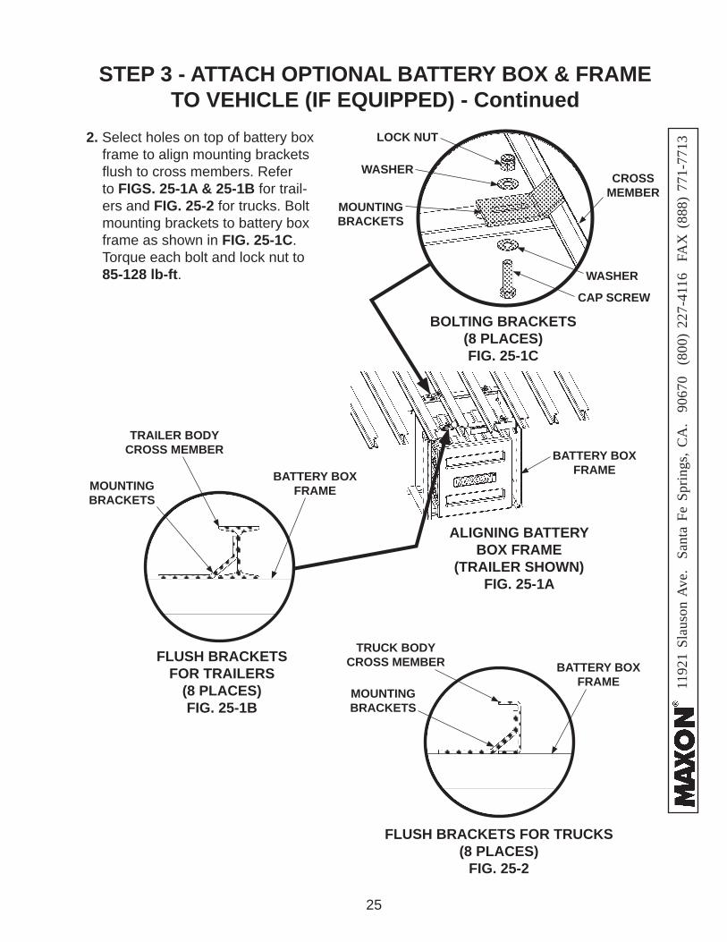
2. Select holes on top of battery box frame to align mounting brackets fl ush to cross members. Refer to FIGS. 25-1A & 25-1B for trail-ers and FIG. 25-2 for trucks. Bolt mounting brackets to battery box frame as shown in FIG. 25-1C. Torque each bolt and lock nut to 85-128 lb-ft.
STEP 3 - ATTACH OPTIONAL BATTERY BOX & FRAME TO VEHICLE (IF EQUIPPED) - Continued
1192
1 Sl
auso
n A
ve.
Sant
a Fe
Spr
ings
, CA
. 90
670
(80
0) 2
27-4
116
FA
X (
888)
771
-771
3
26
STEP 3 - ATTACH OPTIONAL BATTERY BOX & FRAME TO VEHICLE (IF EQUIPPED) - Continued
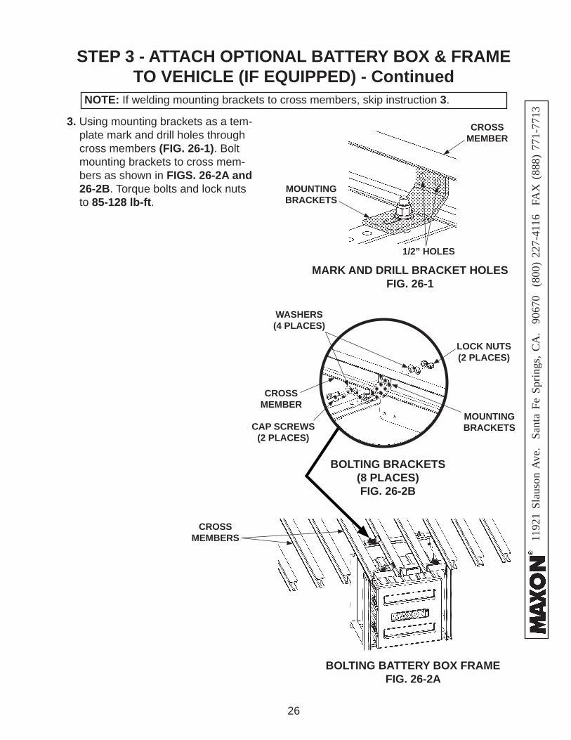
3. Using mounting brackets as a tem-plate mark and drill holes through cross members (FIG. 26-1). Bolt mounting brackets to cross mem-bers as shown in FIGS. 26-2A and 26-2B. Torque bolts and lock nuts to 85-128 lb-ft.
NOTE: If welding mounting brackets to cross members, skip instruction 3.
CROSSMEMBER
CROSSMEMBERS
MOUNTING BRACKETS
1/2” HOLES
BOLTING BATTERY BOX FRAMEFIG. 26-2A
BOLTING BRACKETS(8 PLACES)FIG. 26-2B
CROSSMEMBER
CAP SCREWS(2 PLACES)
WASHERS(4 PLACES)
LOCK NUTS(2 PLACES)
MOUNTING BRACKETS
MARK AND DRILL BRACKET HOLESFIG. 26-1
1192
1 Sl
auso
n A
ve.
Sant
a Fe
Spr
ings
, CA
. 90
670
(80
0) 2
27-4
116
FA
X (
888)
771
-771
3
27
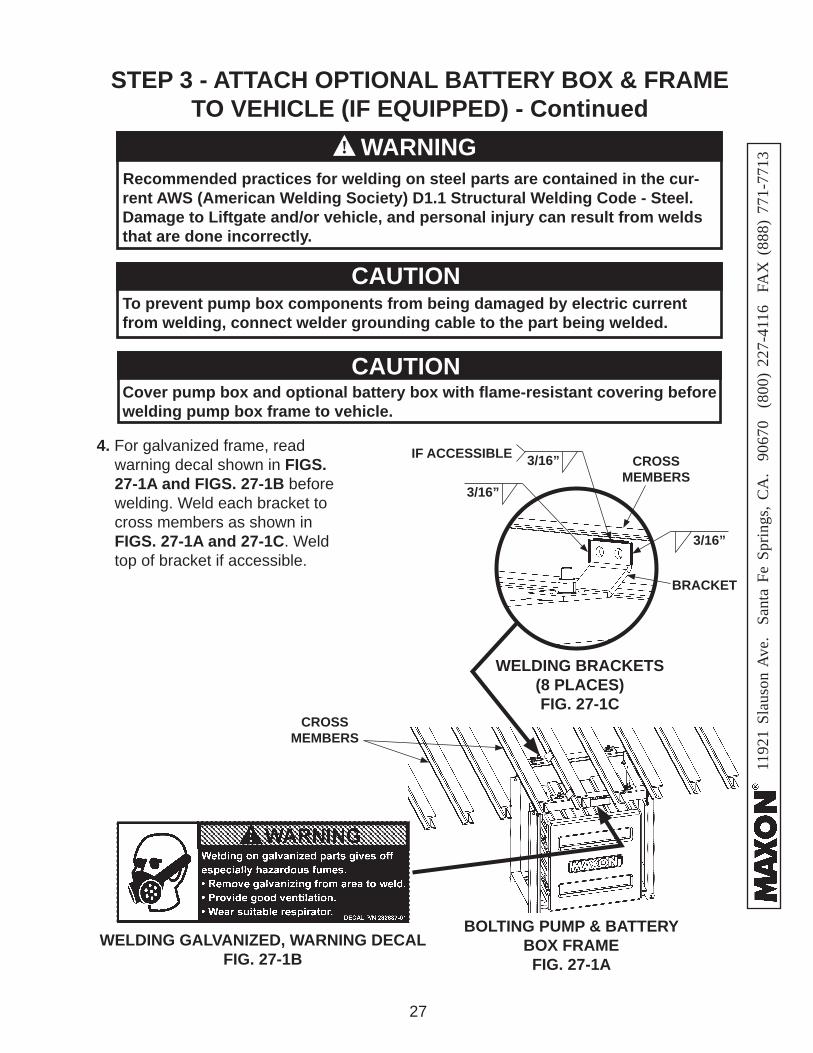
Cover pump box and optional battery box with fl ame-resistant covering before welding pump box frame to vehicle.
CAUTION
To prevent pump box components from being damaged by electric current from welding, connect welder grounding cable to the part being welded.
CAUTION
Recommended practices for welding on steel parts are contained in the cur-rent AWS (American Welding Society) D1.1 Structural Welding Code - Steel. Damage to Liftgate and/or vehicle, and personal injury can result from welds that are done incorrectly.
WARNING!
BOLTING PUMP & BATTERY BOX FRAMEFIG. 27-1A
CROSSMEMBERS
CROSSMEMBERS
BRACKET
WELDING BRACKETS(8 PLACES)FIG. 27-1C
WELDING GALVANIZED, WARNING DECALFIG. 27-1B
3/16”
3/16”
3/16”IF ACCESSIBLE4. For galvanized frame, read warning decal shown in FIGS. 27-1A and FIGS. 27-1B before welding. Weld each bracket to cross members as shown in FIGS. 27-1A and 27-1C. Weld top of bracket if accessible.
STEP 3 - ATTACH OPTIONAL BATTERY BOX & FRAME TO VEHICLE (IF EQUIPPED) - Continued
1192
1 Sl
auso
n A
ve.
Sant
a Fe
Spr
ings
, CA
. 90
670
(80
0) 2
27-4
116
FA
X (
888)
771
-771
3
28
STEP 3 - ATTACH OPTIONAL BATTERY BOX & FRAME TO VEHICLE (IF EQUIPPED) - Continued
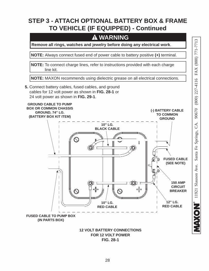
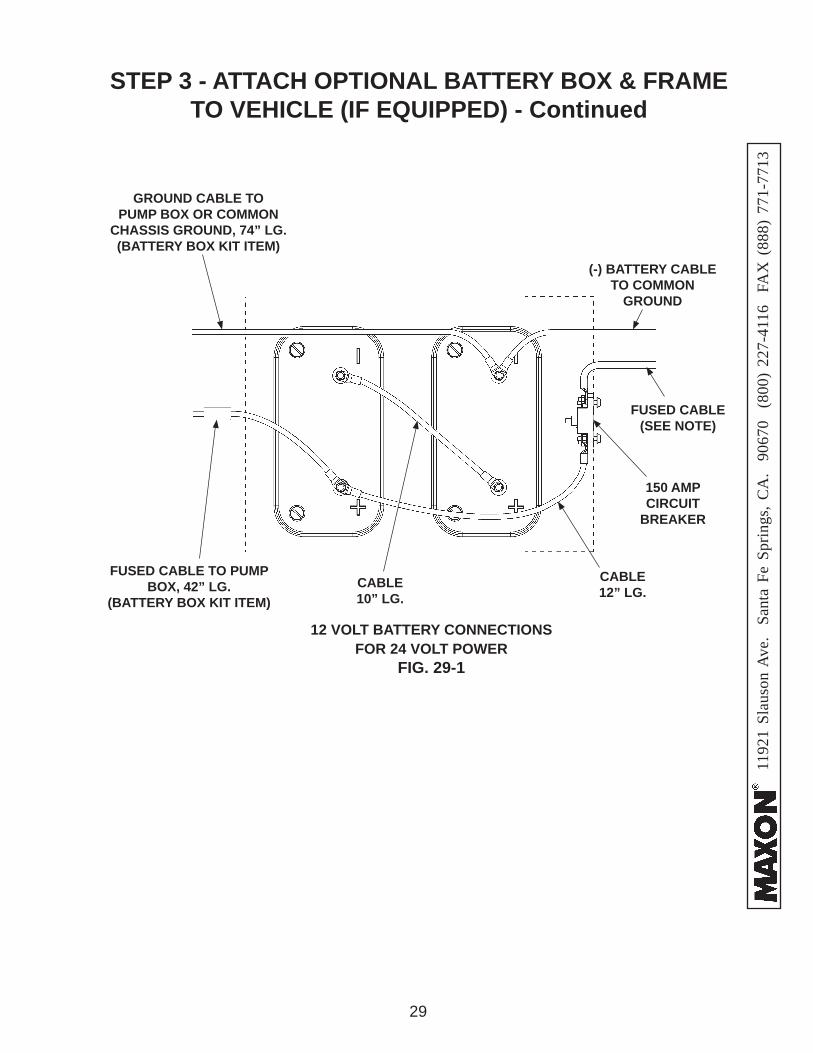
5. Connect battery cables, fused cables, and ground cables for 12 volt power as shown in FIG. 28-1 or 24 volt power as shown in FIG. 29-1.
NOTE: Always connect fused end of power cable to battery positive (+) terminal.
NOTE: To connect charge lines, refer to instructions provided with each charge line kit.
NOTE: MAXON recommends using dielectric grease on all electrical connections.
Remove all rings, watches and jewelry before doing any electrical work.WARNING!
FUSED CABLE(SEE NOTE)
FUSED CABLE TO PUMP BOX (IN PARTS BOX)
10” LG.RED CABLE
GROUND CABLE TO PUMP BOX OR COMMON CHASSIS
GROUND, 74” LG.(BATTERY BOX KIT ITEM)
12 VOLT BATTERY CONNECTIONSFOR 12 VOLT POWER
FIG. 28-1
10” LG.BLACK CABLE
12” LG. RED CABLE
150 AMPCIRCUIT
BREAKER
(-) BATTERY CABLE TO COMMON
GROUND
1192
1 Sl
auso
n A
ve.
Sant
a Fe
Spr
ings
, CA
. 90
670
(80
0) 2
27-4
116
FA
X (
888)
771
-771
3
29
STEP 3 - ATTACH OPTIONAL BATTERY BOX & FRAME TO VEHICLE (IF EQUIPPED) - Continued
FUSED CABLE(SEE NOTE)
(-) BATTERY CABLE TO COMMON
GROUND
FUSED CABLE TO PUMP BOX, 42” LG.
(BATTERY BOX KIT ITEM)
150 AMPCIRCUIT
BREAKER
CABLE12” LG.
CABLE10” LG.
GROUND CABLE TO PUMP BOX OR COMMON
CHASSIS GROUND, 74” LG.(BATTERY BOX KIT ITEM)
12 VOLT BATTERY CONNECTIONSFOR 24 VOLT POWER
FIG. 29-1
1192
1 Sl
auso
n A
ve.
Sant
a Fe
Spr
ings
, CA
. 90
670
(80
0) 2
27-4
116
FA
X (
888)
771
-771
3
30
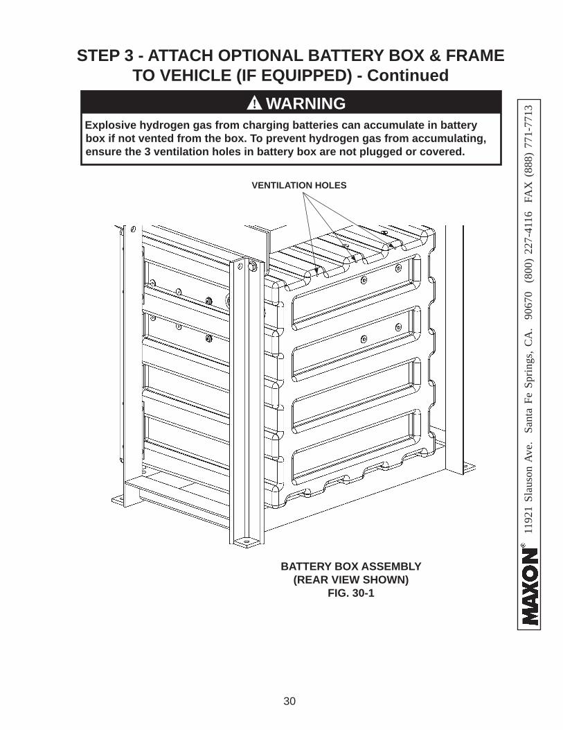
Explosive hydrogen gas from charging batteries can accumulate in battery box if not vented from the box. To prevent hydrogen gas from accumulating, ensure the 3 ventilation holes in battery box are not plugged or covered.
WARNING!
BATTERY BOX ASSEMBLY(REAR VIEW SHOWN)
FIG. 30-1
VENTILATION HOLES
STEP 3 - ATTACH OPTIONAL BATTERY BOX & FRAME TO VEHICLE (IF EQUIPPED) - Continued
1192
1 Sl
auso
n A
ve.
Sant
a Fe
Spr
ings
, CA
. 90
670
(80
0) 2
27-4
116
FA
X (
888)
771
-771
3
31
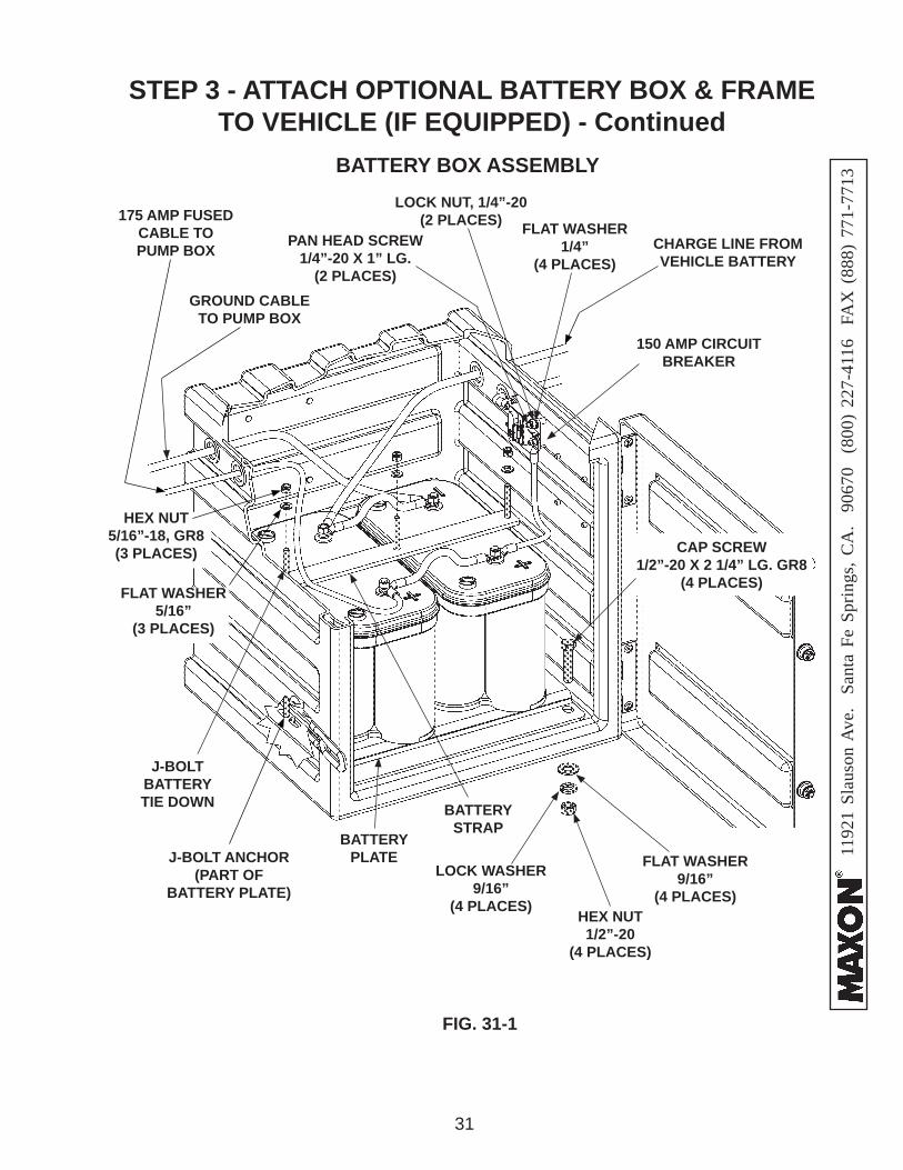
STEP 3 - ATTACH OPTIONAL BATTERY BOX & FRAME TO VEHICLE (IF EQUIPPED) - Continued
BATTERY BOX ASSEMBLY
FIG. 31-1
BATTERYPLATE
BATTERY STRAP
LOCK NUT, 1/4”-20(2 PLACES)
HEX NUT1/2”-20
(4 PLACES)
LOCK WASHER9/16”
(4 PLACES)
FLAT WASHER9/16”
(4 PLACES)
J-BOLT ANCHOR(PART OF
BATTERY PLATE)
FLAT WASHER1/4”
(4 PLACES)PAN HEAD SCREW
1/4”-20 X 1” LG.(2 PLACES)
CAP SCREW1/2”-20 X 2 1/4” LG. GR8
(4 PLACES)
J-BOLT BATTERY TIE DOWN
175 AMP FUSED CABLE TO PUMP BOX
GROUND CABLE TO PUMP BOX
CHARGE LINE FROM VEHICLE BATTERY
150 AMP CIRCUIT BREAKER
FLAT WASHER5/16”
(3 PLACES)
HEX NUT5/16”-18, GR8(3 PLACES)

1192
1 Sl
auso
n A
ve.
Sant
a Fe
Spr
ings
, CA
. 90
670
(80
0) 2
27-4
116
FA
X (
888)
771
-771
3
32
STEP 4 - RUN POWER CABLE
1. Liftgate powered from truck batteries is typically installed on trailers as shown in FIG. 32-1 and on trucks as shown in FIG. 32-2. See the fol-lowing page for running the power cable.
LIFTGATE
RECOMMENDED LIFTGATE & POWER CABLE INSTALLATION ON TRAILER
FIG. 32-1
175 AMP FUSED CABLE
TRACTOR BATTERIES,TYPICAL LOCATION
LIFTGATE
LIFTGATEPOWER UNIT
RECOMMENDED LIFTGATE & POWER CABLEINSTALLATION ON TRUCK
FIG. 32-2
NOTE: Make sure the Liftgate power unit, and all batteries on the vehicle for the power unit, are connected correctly to a common chassis ground.
LIFTGATEPOWER UNIT
175 AMP FUSED CABLE
TRUCK BATTERIES,TYPICAL LOCATION
175 AMP FUSED CABLE
RECOMMENDED CONFIGURATION
1192
1 Sl
auso
n A
ve.
Sant
a Fe
Spr
ings
, CA
. 90
670
(80
0) 2
27-4
116
FA
X (
888)
771
-771
3
33
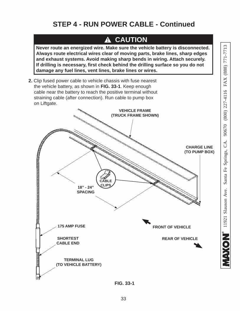
2. Clip fused power cable to vehicle chassis with fuse nearest the vehicle battery, as shown in FIG. 33-1. Keep enough cable near the battery to reach the positive terminal without straining cable (after connection). Run cable to pump box on Liftgate.
FIG. 33-1
Never route an energized wire. Make sure the vehicle battery is disconnected. Always route electrical wires clear of moving parts, brake lines, sharp edges and exhaust systems. Avoid making sharp bends in wiring. Attach securely. If drilling is necessary, fi rst check behind the drilling surface so you do not damage any fuel lines, vent lines, brake lines or wires.
CAUTION
175 AMP FUSE
SHORTEST CABLE END
TERMINAL LUG (TO VEHICLE BATTERY)
VEHICLE FRAME (TRUCK FRAME SHOWN)
18” - 24”SPACING
CHARGE LINE (TO PUMP BOX)
FRONT OF VEHICLE
REAR OF VEHICLE
CABLE CLIPS
!
STEP 4 - RUN POWER CABLE - Continued
1192
1 Sl
auso
n A
ve.
Sant
a Fe
Spr
ings
, CA
. 90
670
(80
0) 2
27-4
116
FA
X (
888)
771
-771
3
34
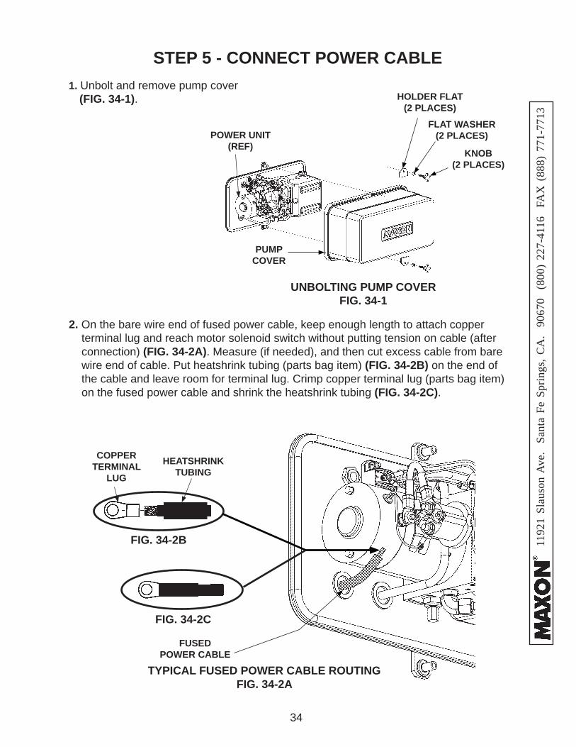
2. On the bare wire end of fused power cable, keep enough length to attach copper terminal lug and reach motor solenoid switch without putting tension on cable (after connection) (FIG. 34-2A). Measure (if needed), and then cut excess cable from bare wire end of cable. Put heatshrink tubing (parts bag item) (FIG. 34-2B) on the end of the cable and leave room for terminal lug. Crimp copper terminal lug (parts bag item) on the fused power cable and shrink the heatshrink tubing (FIG. 34-2C).
STEP 5 - CONNECT POWER CABLE
TYPICAL FUSED POWER CABLE ROUTINGFIG. 34-2A
FIG. 34-2B
COPPER TERMINAL
LUG
HEATSHRINK TUBING
FIG. 34-2C
FUSEDPOWER CABLE
1. Unbolt and remove pump cover (FIG. 34-1).
UNBOLTING PUMP COVERFIG. 34-1
PUMP COVER
KNOB(2 PLACES)
POWER UNIT(REF)
FLAT WASHER(2 PLACES)
HOLDER FLAT(2 PLACES)
1192
1 Sl
auso
n A
ve.
Sant
a Fe
Spr
ings
, CA
. 90
670
(80
0) 2
27-4
116
FA
X (
888)
771
-771
3
35
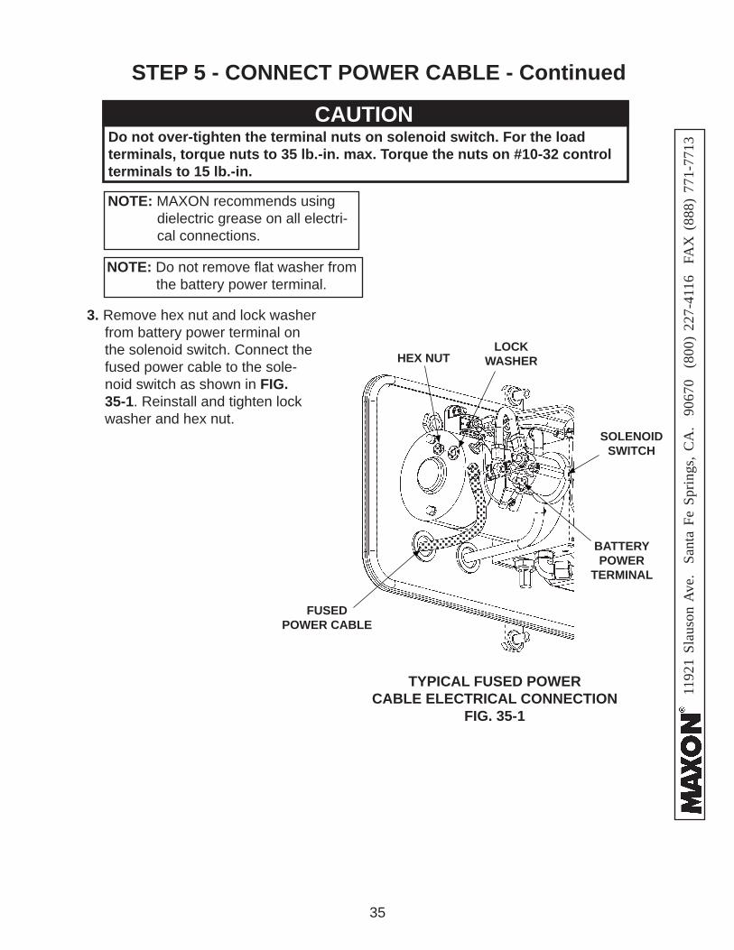
3. Remove hex nut and lock washer from battery power terminal on the solenoid switch. Connect the fused power cable to the sole-noid switch as shown in FIG. 35-1. Reinstall and tighten lock washer and hex nut.
TYPICAL FUSED POWERCABLE ELECTRICAL CONNECTION
FIG. 35-1
NOTE: MAXON recommends using dielectric grease on all electri-cal connections.
Do not over-tighten the terminal nuts on solenoid switch. For the load terminals, torque nuts to 35 lb.-in. max. Torque the nuts on #10-32 control terminals to 15 lb.-in.
CAUTION
NOTE: Do not remove fl at washer from the battery power terminal.
FUSEDPOWER CABLE
BATTERY POWER
TERMINAL
SOLENOID SWITCH
HEX NUTLOCK
WASHER
STEP 5 - CONNECT POWER CABLE - Continued

1192
1 Sl
auso
n A
ve.
Sant
a Fe
Spr
ings
, CA
. 90
670
(80
0) 2
27-4
116
FA
X (
888)
771
-771
3
36
STEP 6 - INSTALL CONTROL SWITCH
DRILLING MOUNTING HOLES FIG. 36-1
1. Drill one 3/4“ hole and two #21–size holes in the vertical post on curb side of vehicle body as shown in FIG. 36-1.
VEHICLE BODY VERTICAL POST
(CURB SIDE)
1192
1 Sl
auso
n A
ve.
Sant
a Fe
Spr
ings
, CA
. 90
670
(80
0) 2
27-4
116
FA
X (
888)
771
-771
3
37
STEP 6 - INSTALL CONTROL SWITCH - ContinuedSTEP 6 - INSTALL CONTROL SWITCH - Continued
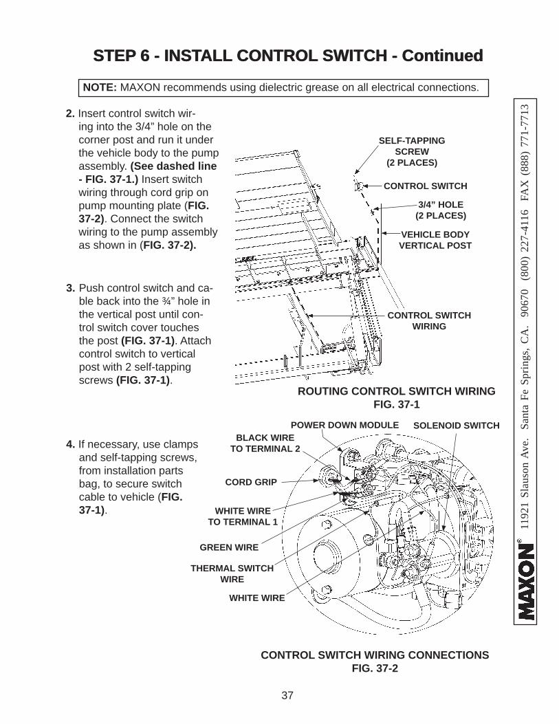
NOTE: MAXON recommends using dielectric grease on all electrical connections.
2. Insert control switch wir-ing into the 3/4” hole on the corner post and run it under the vehicle body to the pump assembly. (See dashed line - FIG. 37-1.) Insert switch wiring through cord grip on pump mounting plate (FIG. 37-2). Connect the switch wiring to the pump assembly as shown in (FIG. 37-2).
3. Push control switch and ca-ble back into the ¾” hole in the vertical post until con-trol switch cover touches the post (FIG. 37-1). Attach control switch to vertical post with 2 self-tapping screws (FIG. 37-1).
4. If necessary, use clamps and self-tapping screws, from installation parts bag, to secure switch cable to vehicle (FIG. 37-1).
ROUTING CONTROL SWITCH WIRING FIG. 37-1
3/4” HOLE(2 PLACES)
VEHICLE BODY VERTICAL POST
CONTROL SWITCH WIRING
CONTROL SWITCH
CONTROL SWITCH WIRING CONNECTIONS FIG. 37-2
SELF-TAPPING SCREW
(2 PLACES)
SOLENOID SWITCHPOWER DOWN MODULE
WHITE WIRE
THERMAL SWITCH WIRE
GREEN WIRE
CORD GRIP
WHITE WIRE TO TERMINAL 1
BLACK WIRE TO TERMINAL 2
1192
1 Sl
auso
n A
ve.
Sant
a Fe
Spr
ings
, CA
. 90
670
(80
0) 2
27-4
116
FA
X (
888)
771
-771
3
38
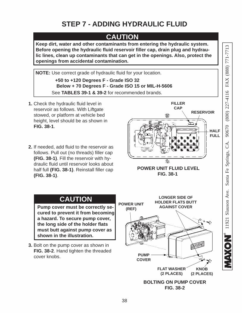
STEP 7 - ADDING HYDRAULIC FLUID
CAUTIONKeep dirt, water and other contaminants from entering the hydraulic system. Before opening the hydraulic fl uid reservoir fi ller cap, drain plug and hydrau-lic lines, clean up contaminants that can get in the openings. Also, protect the openings from accidental contamination.
+50 to +120 Degrees F - Grade ISO 32 Below + 70 Degrees F - Grade ISO 15 or MIL-H-5606
NOTE: Use correct grade of hydraulic fl uid for your location.
See TABLES 39-1 & 39-2 for recommended brands.
2. If needed, add fl uid to the reservoir as follows. Pull out (no threads) fi ller cap (FIG. 38-1). Fill the reservoir with hy-draulic fl uid until reservoir looks about half full (FIG. 38-1). Reinstall fi ller cap (FIG. 38-1).
POWER UNIT FLUID LEVELFIG. 38-1
FILLER CAP
3. Bolt on the pump cover as shown in FIG. 38-2. Hand tighten the threaded cover knobs.
1. Check the hydraulic fl uid level in reservoir as follows. With Liftgate stowed, or platform at vehicle bed height, level should be as shown in FIG. 38-1.
CAUTIONPump cover must be correctly se-cured to prevent it from becoming a hazard. To secure pump cover, the long side of the holder fl ats must butt against pump cover as shown in the illustration.
RESERVOIR
HALF FULL
LONGER SIDE OF HOLDER FLATS BUTT
AGAINST COVER
BOLTING ON PUMP COVERFIG. 38-2
PUMP COVER
KNOB(2 PLACES)
POWER UNIT(REF)
FLAT WASHER(2 PLACES)
1192
1 Sl
auso
n A
ve.
Sant
a Fe
Spr
ings
, CA
. 90
670
(80
0) 2
27-4
116
FA
X (
888)
771
-771
3
39
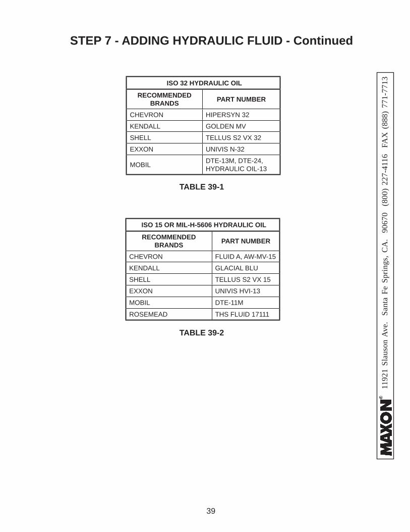
TABLE 39-2
TABLE 39-1
ISO 32 HYDRAULIC OIL
RECOMMENDED BRANDS PART NUMBER
CHEVRON HIPERSYN 32
KENDALL GOLDEN MV
SHELL TELLUS S2 VX 32
EXXON UNIVIS N-32
MOBIL DTE-13M, DTE-24,HYDRAULIC OIL-13
ISO 15 OR MIL-H-5606 HYDRAULIC OIL
RECOMMENDED BRANDS PART NUMBER
CHEVRON FLUID A, AW-MV-15
KENDALL GLACIAL BLU
SHELL TELLUS S2 VX 15
EXXON UNIVIS HVI-13
MOBIL DTE-11M
ROSEMEAD THS FLUID 17111
STEP 7 - ADDING HYDRAULIC FLUID - Continued
1192
1 Sl
auso
n A
ve.
Sant
a Fe
Spr
ings
, CA
. 90
670
(80
0) 2
27-4
116
FA
X (
888)
771
-771
3
40
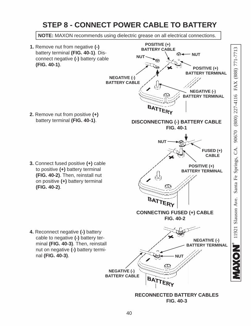
STEP 8 - CONNECT POWER CABLE TO BATTERY
1. Remove nut from negative (-) battery terminal (FIG. 40-1). Dis-connect negative (-) battery cable (FIG. 40-1).
DISCONNECTING (-) BATTERY CABLEFIG. 40-1
NOTE: MAXON recommends using dielectric grease on all electrical connections.
NEGATIVE (-) BATTERY TERMINAL
NEGATIVE (-) BATTERY CABLE
RECONNECTED BATTERY CABLESFIG. 40-3
POSITIVE (+) BATTERY TERMINAL
POSITIVE (+) BATTERY CABLE
NUTNUT
2. Remove nut from positive (+) battery terminal (FIG. 40-1).
3. Connect fused positive (+) cable to positive (+) battery terminal (FIG. 40-2). Then, reinstall nut on positive (+) battery terminal (FIG. 40-2).
4. Reconnect negative (-) battery cable to negative (-) battery ter-minal (FIG. 40-3). Then, reinstall nut on negative (-) battery termi-nal (FIG. 40-3).
CONNECTING FUSED (+) CABLEFIG. 40-2
POSITIVE (+) BATTERY TERMINAL
FUSED (+) CABLE
NEGATIVE (-) BATTERY CABLE
NEGATIVE (-) BATTERY TERMINAL
NUT
NUT
1192
1 Sl
auso
n A
ve.
Sant
a Fe
Spr
ings
, CA
. 90
670
(80
0) 2
27-4
116
FA
X (
888)
771
-771
3
41
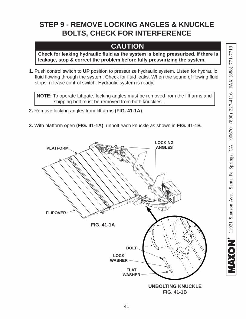
STEP 9 - REMOVE LOCKING ANGLES & KNUCKLE BOLTS, CHECK FOR INTERFERENCE
1. Push control switch to UP position to pressurize hydraulic system. Listen for hydraulic fl uid fl owing through the system. Check for fl uid leaks. When the sound of fl owing fl uid stops, release control switch. Hydraulic system is ready.
2. Remove locking angles from lift arms (FIG. 41-1A).
NOTE: To operate Liftgate, locking angles must be removed from the lift arms and shipping bolt must be removed from both knuckles.
3. With platform open (FIG. 41-1A), unbolt each knuckle as shown in FIG. 41-1B.
FLIPOVER
PLATFORMLOCKING ANGLES
CAUTIONCheck for leaking hydraulic fl uid as the system is being pressurized. If there is leakage, stop & correct the problem before fully pressurizing the system.
FIG. 41-1A
UNBOLTING KNUCKLEFIG. 41-1B
BOLT
FLATWASHER
LOCKWASHER
1192
1 Sl
auso
n A
ve.
Sant
a Fe
Spr
ings
, CA
. 90
670
(80
0) 2
27-4
116
FA
X (
888)
771
-771
3
42
STEP 9 - REMOVE LOCKING ANGLES & KNUCKLE BOLTS, CHECK FOR INTERFERENCE - Continued
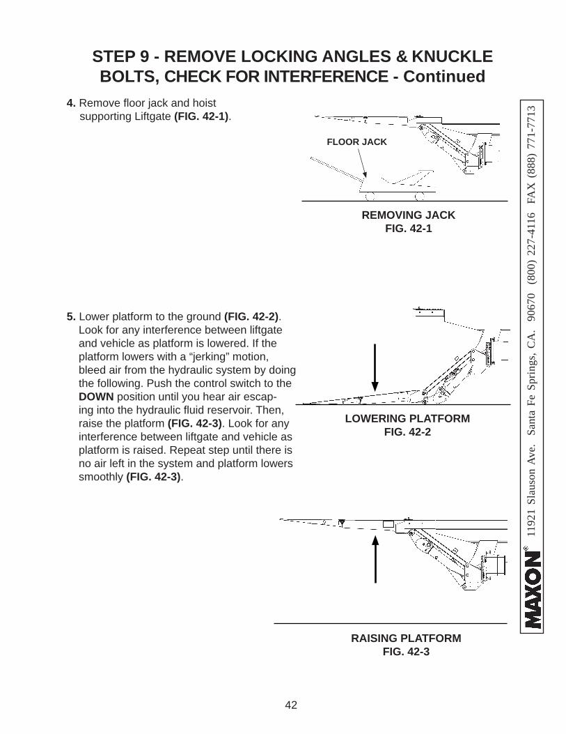
5. Lower platform to the ground (FIG. 42-2). Look for any interference between liftgate and vehicle as platform is lowered. If the platform lowers with a “jerking” motion, bleed air from the hydraulic system by doing the following. Push the control switch to the DOWN position until you hear air escap-ing into the hydraulic fl uid reservoir. Then, raise the platform (FIG. 42-3). Look for any interference between liftgate and vehicle as platform is raised. Repeat step until there is no air left in the system and platform lowers smoothly (FIG. 42-3).
4. Remove fl oor jack and hoist supporting Liftgate (FIG. 42-1).
REMOVING JACKFIG. 42-1
FLOOR JACK
LOWERING PLATFORMFIG. 42-2
RAISING PLATFORMFIG. 42-3
1192
1 Sl
auso
n A
ve.
Sant
a Fe
Spr
ings
, CA
. 90
670
(80
0) 2
27-4
116
FA
X (
888)
771
-771
3
43
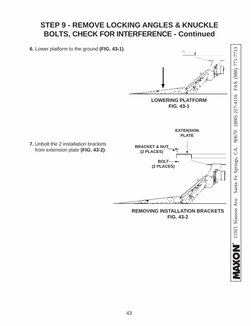
BRACKET & NUT (2 PLACES)
6. Lower platform to the ground (FIG. 43-1).
REMOVING INSTALLATION BRACKETSFIG. 43-2
7. Unbolt the 2 installation brackets from extension plate (FIG. 43-2).
BOLT(2 PLACES)
EXTENSIONPLATE
LOWERING PLATFORMFIG. 43-1
STEP 9 - REMOVE LOCKING ANGLES & KNUCKLE BOLTS, CHECK FOR INTERFERENCE - Continued
1192
1 Sl
auso
n A
ve.
Sant
a Fe
Spr
ings
, CA
. 90
670
(80
0) 2
27-4
116
FA
X (
888)
771
-771
3
44
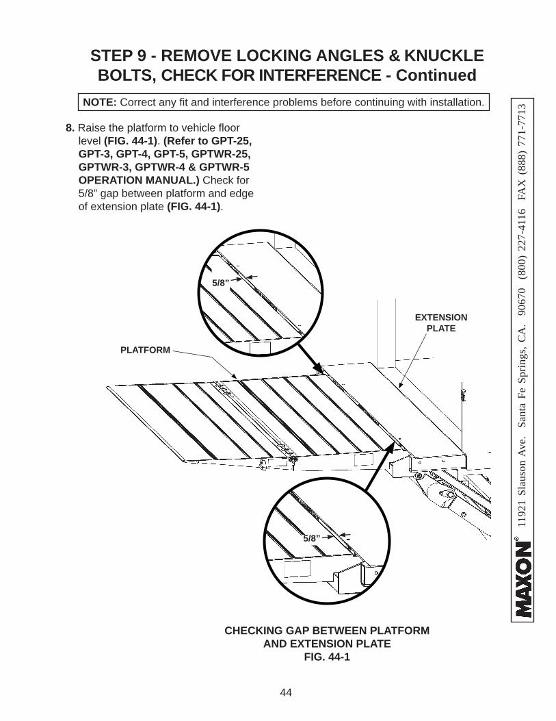
8. Raise the platform to vehicle fl oor level (FIG. 44-1). (Refer to GPT-25, GPT-3, GPT-4, GPT-5, GPTWR-25, GPTWR-3, GPTWR-4 & GPTWR-5 OPERATION MANUAL.) Check for 5/8” gap between platform and edge of extension plate (FIG. 44-1).
PLATFORM
EXTENSION PLATE
NOTE: Correct any fi t and interference problems before continuing with installation.
CHECKING GAP BETWEEN PLATFORM AND EXTENSION PLATE
FIG. 44-1
5/8”
5/8”
STEP 9 - REMOVE LOCKING ANGLES & KNUCKLE BOLTS, CHECK FOR INTERFERENCE - Continued
1192
1 Sl
auso
n A
ve.
Sant
a Fe
Spr
ings
, CA
. 90
670
(80
0) 2
27-4
116
FA
X (
888)
771
-771
3
45
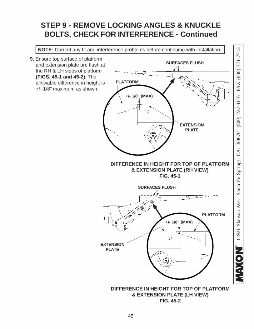
9. Ensure top surface of platform and extension plate are fl ush at the RH & LH sides of platform (FIGS. 45-1 and 45-2). The allowable difference in height is +/- 1/8” maximum as shown.
SURFACES FLUSH
+/- 1/8” (MAX)
SURFACES FLUSH
EXTENSIONPLATE
EXTENSIONPLATE
PLATFORM
PLATFORM
DIFFERENCE IN HEIGHT FOR TOP OF PLATFORM & EXTENSION PLATE (RH VIEW)
FIG. 45-1
DIFFERENCE IN HEIGHT FOR TOP OF PLATFORM & EXTENSION PLATE (LH VIEW)
FIG. 45-2
NOTE: Correct any fi t and interference problems before continuing with installation.
+/- 1/8” (MAX)
STEP 9 - REMOVE LOCKING ANGLES & KNUCKLE BOLTS, CHECK FOR INTERFERENCE - Continued
1192
1 Sl
auso
n A
ve.
Sant
a Fe
Spr
ings
, CA
. 90
670
(80
0) 2
27-4
116
FA
X (
888)
771
-771
3
46
STEP 10 - INSTALL OPENER, LICENSE PLATE BRACKET, & ICC BUMPER (IF EQUIPPED)
To prevent personal injury and equipment damage, keep the Liftgate from being operated while working between the platform and extension plate.
WARNING!
DISCONNECTING POWERFIG. 46-2
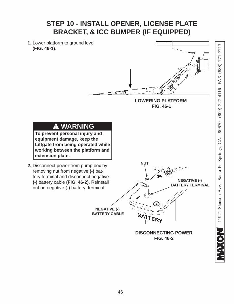
2. Disconnect power from pump box by removing nut from negative (-) bat-tery terminal and disconnect negative (-) battery cable (FIG. 46-2). Reinstall nut on negative (-) battery terminal.
NEGATIVE (-) BATTERY CABLE
NEGATIVE (-) BATTERY TERMINAL
NUT
1. Lower platform to ground level (FIG. 46-1).
LOWERING PLATFORM FIG. 46-1
1192
1 Sl
auso
n A
ve.
Sant
a Fe
Spr
ings
, CA
. 90
670
(80
0) 2
27-4
116
FA
X (
888)
771
-771
3
47
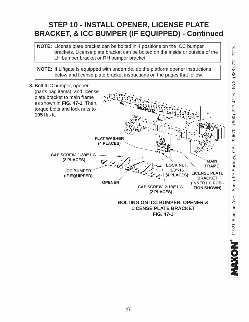
NOTE: License plate bracket can be bolted in 4 positions on the ICC bumper brackets. License plate bracket can be bolted on the inside or outside of the LH bumper bracket or RH bumper bracket.
STEP 10 - INSTALL OPENER, LICENSE PLATE BRACKET, & ICC BUMPER (IF EQUIPPED) - Continued
3. Bolt ICC bumper, opener (parts bag items), and license plate bracket to main frame as shown in FIG. 47-1. Then, torque bolts and lock nuts to 105 lb.-ft.
BOLTING ON ICC BUMPER, OPENER & LICENSE PLATE BRACKET
FIG. 47-1
OPENER
LOCK NUT, 3/8”-16
(4 PLACES)
MAIN FRAME
FLAT WASHER(4 PLACES)
LICENSE PLATE BRACKET
(INNER LH POSI-TION SHOWN)
CAP SCREW, 1-3/4” LG.(2 PLACES)
ICC BUMPER(IF EQUIPPED)
CAP SCREW, 2-1/4” LG.(2 PLACES)
NOTE: If Liftgate is equipped with underride, do the platform opener instructions below and license plate bracket instructions on the pages that follow.
1192
1 Sl
auso
n A
ve.
Sant
a Fe
Spr
ings
, CA
. 90
670
(80
0) 2
27-4
116
FA
X (
888)
771
-771
3
48
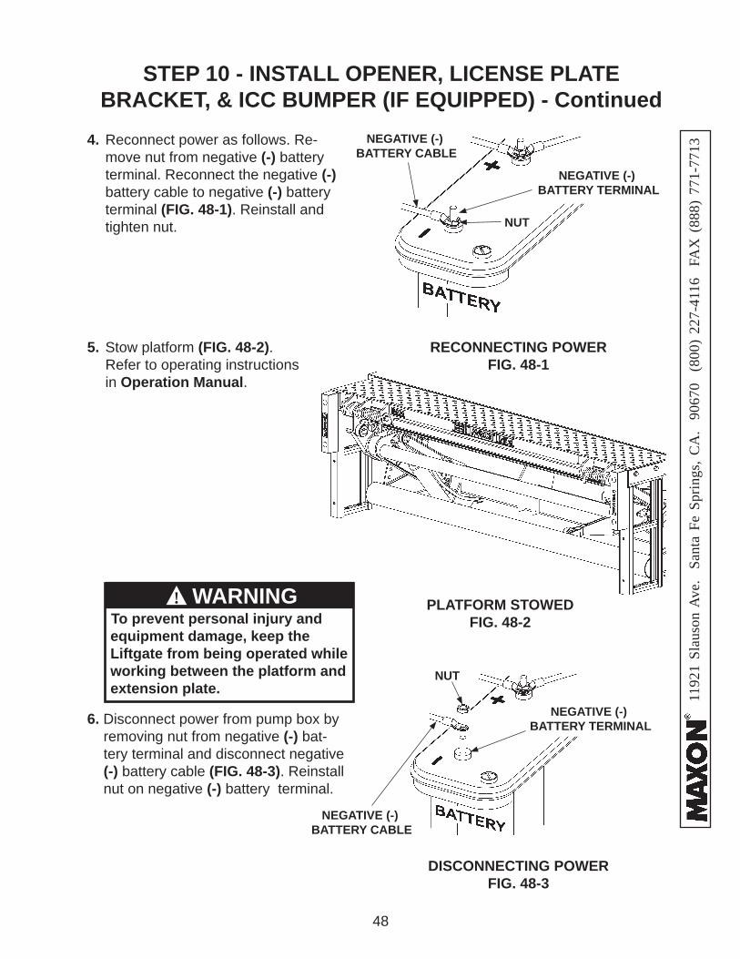
4. Reconnect power as follows. Re-move nut from negative (-) battery terminal. Reconnect the negative (-) battery cable to negative (-) battery terminal (FIG. 48-1). Reinstall and tighten nut.
RECONNECTING POWERFIG. 48-1
STEP 10 - INSTALL OPENER, LICENSE PLATE BRACKET, & ICC BUMPER (IF EQUIPPED) - Continued
NEGATIVE (-) BATTERY TERMINAL
NUT
NEGATIVE (-) BATTERY CABLE
5. Stow platform (FIG. 48-2). Refer to operating instructions in Operation Manual.
PLATFORM STOWEDFIG. 48-2To prevent personal injury and
equipment damage, keep the Liftgate from being operated while working between the platform and extension plate.
WARNING!
DISCONNECTING POWERFIG. 48-3
6. Disconnect power from pump box by removing nut from negative (-) bat-tery terminal and disconnect negative (-) battery cable (FIG. 48-3). Reinstall nut on negative (-) battery terminal.
NEGATIVE (-) BATTERY CABLE
NEGATIVE (-) BATTERY TERMINAL
NUT
1192
1 Sl
auso
n A
ve.
Sant
a Fe
Spr
ings
, CA
. 90
670
(80
0) 2
27-4
116
FA
X (
888)
771
-771
3
49
STEP 10 - INSTALL OPENER, LICENSE PLATE BRACKET, & ICC BUMPER (IF EQUIPPED) - Continued
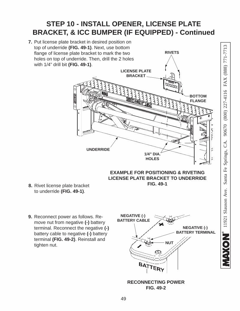
7. Put license plate bracket in desired position on top of underride (FIG. 49-1). Next, use bottom fl ange of license plate bracket to mark the two holes on top of underride. Then, drill the 2 holes with 1/4” drill bit (FIG. 49-1).
8. Rivet license plate bracket to underride (FIG. 49-1).
EXAMPLE FOR POSITIONING & RIVETING LICENSE PLATE BRACKET TO UNDERRIDE
FIG. 49-1
RIVETS
1/4” DIA.HOLES
BOTTOM FLANGE
LICENSE PLATE BRACKET
UNDERRIDE
9. Reconnect power as follows. Re-move nut from negative (-) battery terminal. Reconnect the negative (-) battery cable to negative (-) battery terminal (FIG. 49-2). Reinstall and tighten nut.
RECONNECTING POWERFIG. 49-2
NEGATIVE (-) BATTERY TERMINAL
NUT
NEGATIVE (-) BATTERY CABLE
1192
1 Sl
auso
n A
ve.
Sant
a Fe
Spr
ings
, CA
. 90
670
(80
0) 2
27-4
116
FA
X (
888)
771
-771
3
50
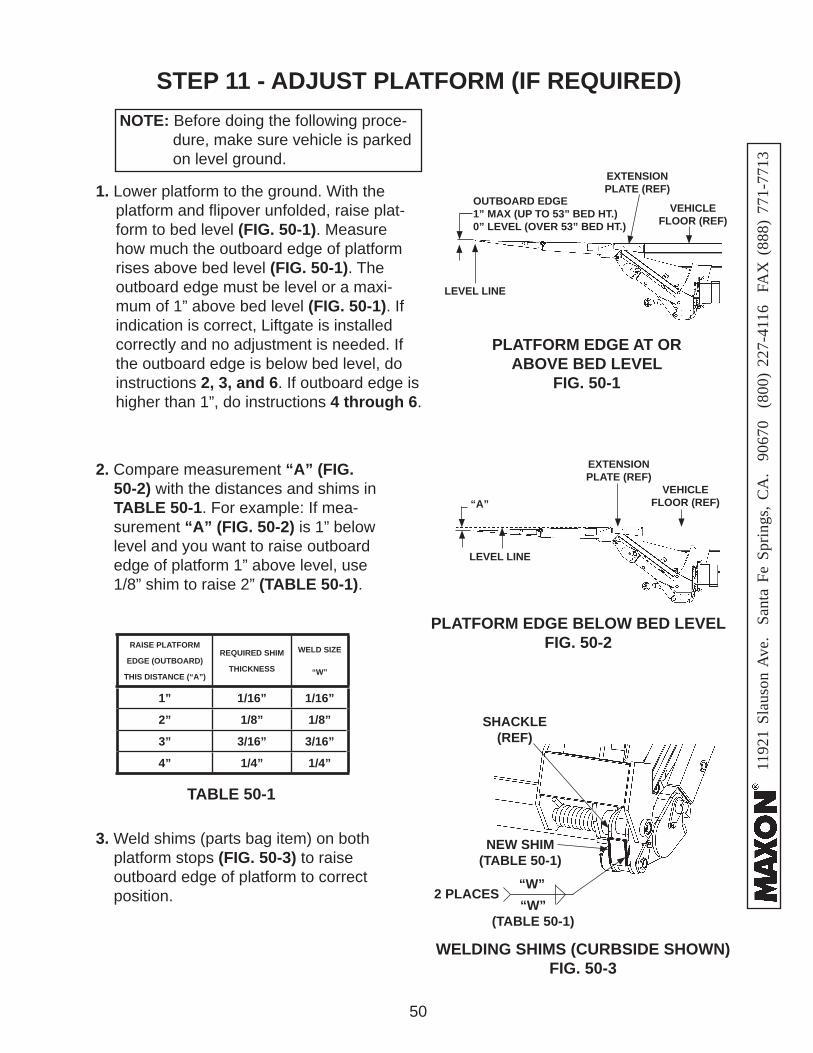
STEP 11 - ADJUST PLATFORM (IF REQUIRED)NOTE: Before doing the following proce- dure, make sure vehicle is parked on level ground.
PLATFORM EDGE AT OR ABOVE BED LEVEL
FIG. 50-1
1. Lower platform to the ground. With the platform and fl ipover unfolded, raise plat-form to bed level (FIG. 50-1). Measure how much the outboard edge of platform rises above bed level (FIG. 50-1). The outboard edge must be level or a maxi-mum of 1” above bed level (FIG. 50-1). If indication is correct, Liftgate is installed correctly and no adjustment is needed. If the outboard edge is below bed level, do instructions 2, 3, and 6. If outboard edge is higher than 1”, do instructions 4 through 6.
3. Weld shims (parts bag item) on both platform stops (FIG. 50-3) to raise outboard edge of platform to correct position.
PLATFORM EDGE BELOW BED LEVEL FIG. 50-2
LEVEL LINE
“A”
SHACKLE(REF)
WELDING SHIMS (CURBSIDE SHOWN)FIG. 50-3
“W”(TABLE 50-1)
TABLE 50-1
RAISE PLATFORM
EDGE (OUTBOARD)
THIS DISTANCE (“A”)
REQUIRED SHIM
THICKNESS
WELD SIZE
“W”
1” 1/16” 1/16”
2” 1/8” 1/8”
3” 3/16” 3/16”
4” 1/4” 1/4”
NEW SHIM(TABLE 50-1)
2 PLACES
2. Compare measurement “A” (FIG. 50-2) with the distances and shims in TABLE 50-1. For example: If mea-surement “A” (FIG. 50-2) is 1” below level and you want to raise outboard edge of platform 1” above level, use 1/8” shim to raise 2” (TABLE 50-1).
VEHICLEFLOOR (REF)
EXTENSIONPLATE (REF)
LEVEL LINE
VEHICLEFLOOR (REF)
EXTENSIONPLATE (REF)
OUTBOARD EDGE 1” MAX (UP TO 53” BED HT.)0” LEVEL (OVER 53” BED HT.)
“W”
1192
1 Sl
auso
n A
ve.
Sant
a Fe
Spr
ings
, CA
. 90
670
(80
0) 2
27-4
116
FA
X (
888)
771
-771
3
51
STEP 11 - ADJUST PLATFORM - Continued
LOWER PLATFORM EDGE (OUTBOARD)
THIS DISTANCE (“B”)
GRIND METAL FROM PLATFORM
STOP
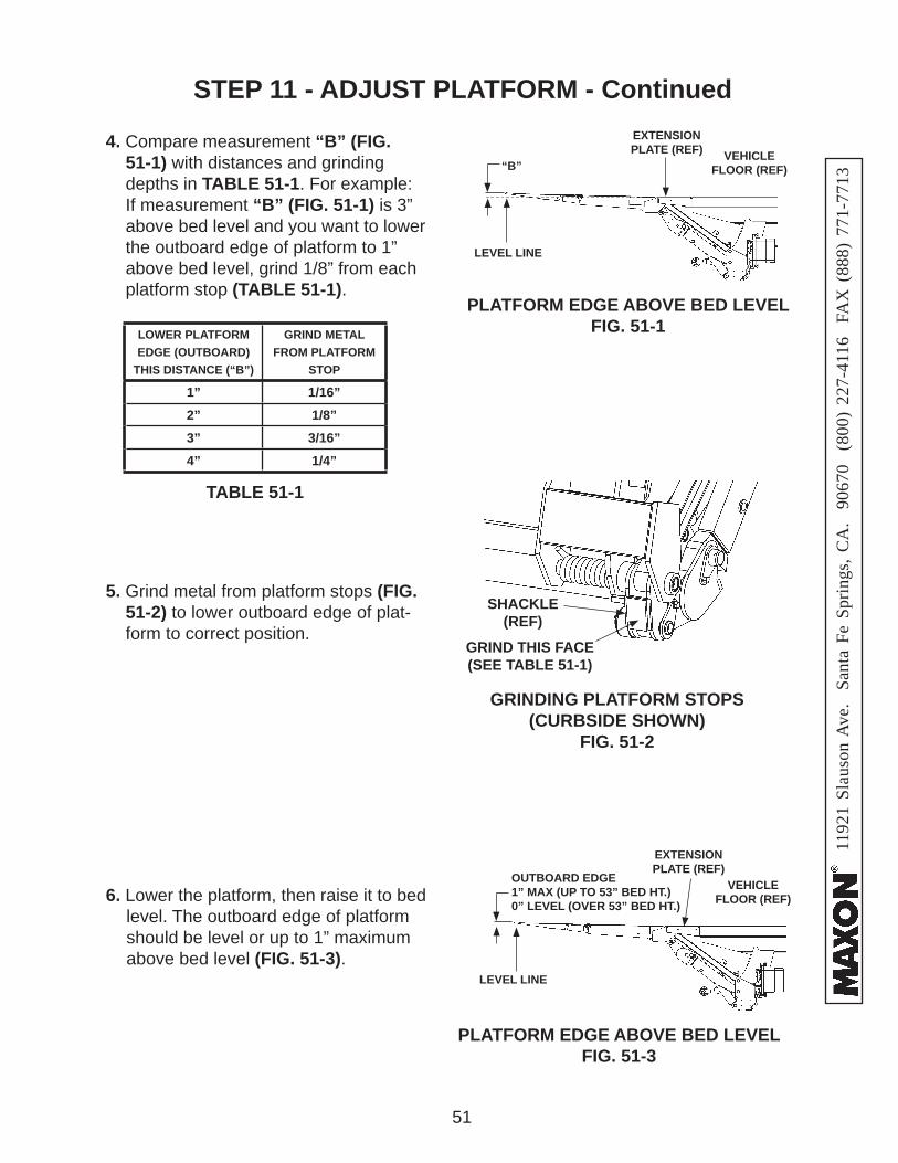
1” 1/16”2” 1/8”3” 3/16”4” 1/4”
TABLE 51-1
6. Lower the platform, then raise it to bed level. The outboard edge of platform should be level or up to 1” maximum above bed level (FIG. 51-3).
4. Compare measurement “B” (FIG. 51-1) with distances and grinding depths in TABLE 51-1. For example: If measurement “B” (FIG. 51-1) is 3” above bed level and you want to lower the outboard edge of platform to 1” above bed level, grind 1/8” from each platform stop (TABLE 51-1).
5. Grind metal from platform stops (FIG. 51-2) to lower outboard edge of plat-form to correct position.
GRINDING PLATFORM STOPS (CURBSIDE SHOWN)
FIG. 51-2
GRIND THIS FACE(SEE TABLE 51-1)
SHACKLE(REF)
PLATFORM EDGE ABOVE BED LEVEL FIG. 51-1
LEVEL LINE
“B”
PLATFORM EDGE ABOVE BED LEVEL FIG. 51-3
VEHICLEFLOOR (REF)
EXTENSIONPLATE (REF)
LEVEL LINE
VEHICLEFLOOR (REF)
EXTENSIONPLATE (REF)
OUTBOARD EDGE 1” MAX (UP TO 53” BED HT.)0” LEVEL (OVER 53” BED HT.)
1192
1 Sl
auso
n A
ve.
Sant
a Fe
Spr
ings
, CA
. 90
670
(80
0) 2
27-4
116
FA
X (
888)
771
-771
3
52
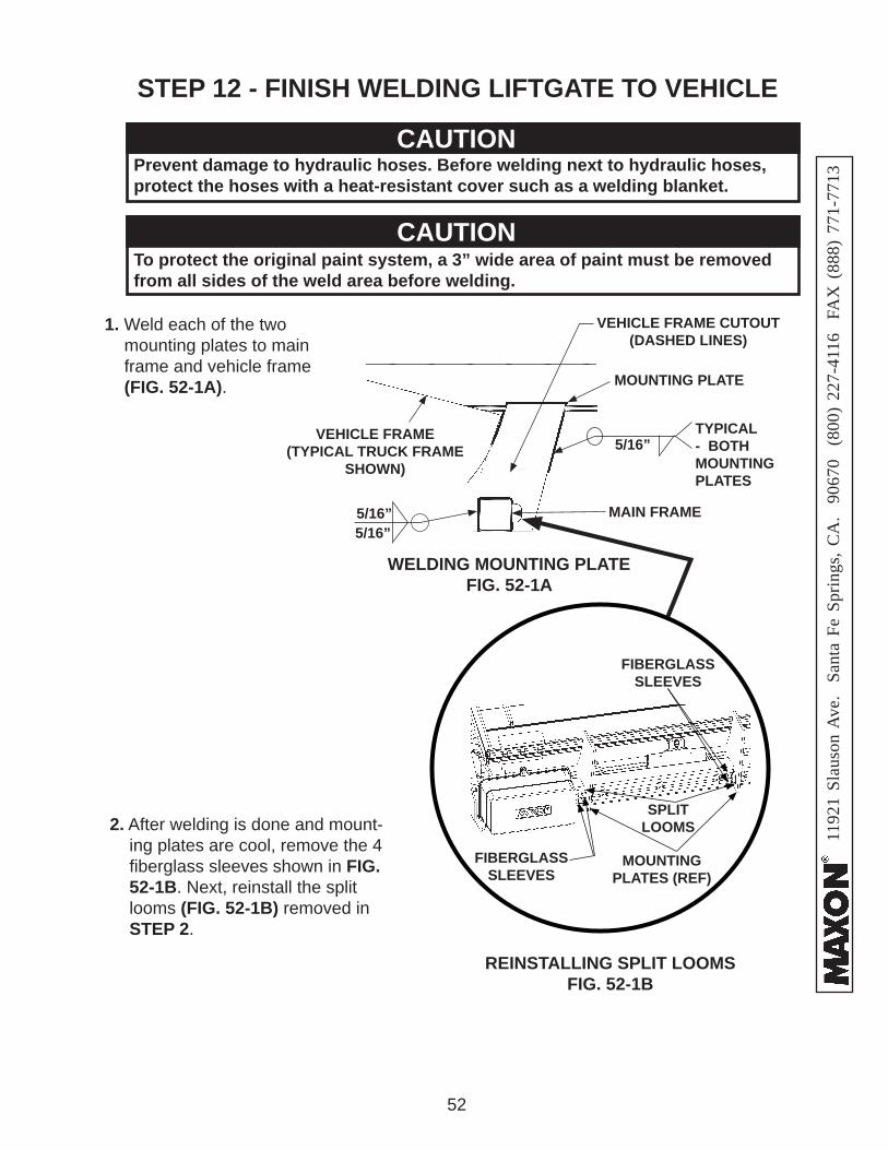
STEP 12 - FINISH WELDING LIFTGATE TO VEHICLE
MOUNTING PLATE
WELDING MOUNTING PLATE FIG. 52-1A
TYPICAL - BOTHMOUNTING PLATES
5/16”VEHICLE FRAME
(TYPICAL TRUCK FRAME SHOWN)
VEHICLE FRAME CUTOUT(DASHED LINES)
Prevent damage to hydraulic hoses. Before welding next to hydraulic hoses, protect the hoses with a heat-resistant cover such as a welding blanket.
CAUTION
2. After welding is done and mount-ing plates are cool, remove the 4 fi berglass sleeves shown in FIG. 52-1B. Next, reinstall the split looms (FIG. 52-1B) removed in STEP 2.
REINSTALLING SPLIT LOOMSFIG. 52-1B
SPLIT LOOMS
FIBERGLASS SLEEVES
MOUNTINGPLATES (REF)
FIBERGLASS SLEEVES
To protect the original paint system, a 3” wide area of paint must be removed from all sides of the weld area before welding.
CAUTION
5/16”MAIN FRAME
1. Weld each of the two mounting plates to main frame and vehicle frame (FIG. 52-1A).
5/16”
1192
1 Sl
auso
n A
ve.
Sant
a Fe
Spr
ings
, CA
. 90
670
(80
0) 2
27-4
116
FA
X (
888)
771
-771
3
53
PLATFORM LOWERED TO GROUNDFIG. 53-1
To prevent personal injury and equipment damage, keep the Liftgate from being operated while installing steps on extension plate.
WARNING!
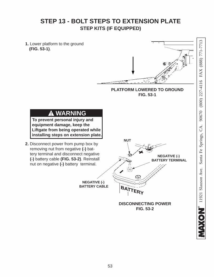
1. Lower platform to the ground (FIG. 53-1).
DISCONNECTING POWERFIG. 53-2
2. Disconnect power from pump box by removing nut from negative (-) bat-tery terminal and disconnect negative (-) battery cable (FIG. 53-2). Reinstall nut on negative (-) battery terminal.
NEGATIVE (-) BATTERY CABLE
NEGATIVE (-) BATTERY TERMINAL
NUT
STEP 13 - BOLT STEPS TO EXTENSION PLATE STEP KITS (IF EQUIPPED)
1192
1 Sl
auso
n A
ve.
Sant
a Fe
Spr
ings
, CA
. 90
670
(80
0) 2
27-4
116
FA
X (
888)
771
-771
3
54
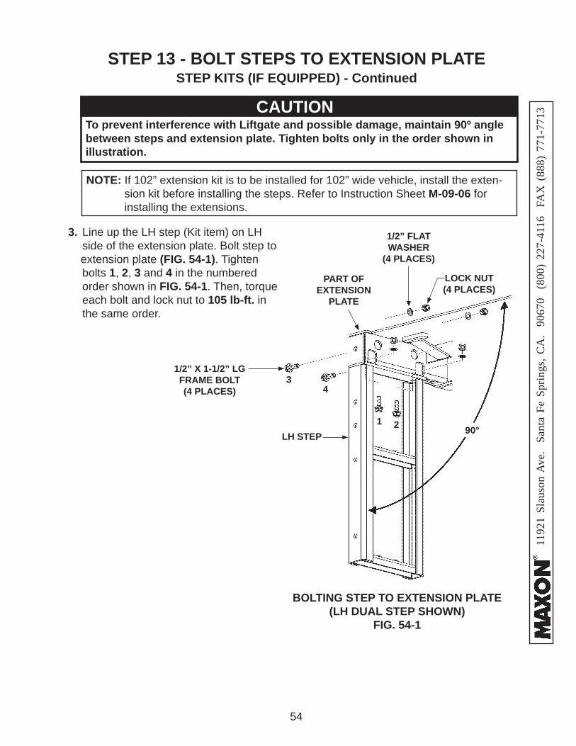
NOTE: If 102” extension kit is to be installed for 102” wide vehicle, install the exten-sion kit before installing the steps. Refer to Instruction Sheet M-09-06 for installing the extensions.
3. Line up the LH step (Kit item) on LH side of the extension plate. Bolt step to
extension plate (FIG. 54-1). Tighten bolts 1, 2, 3 and 4 in the numbered order shown in FIG. 54-1. Then, torque each bolt and lock nut to 105 lb-ft. in the same order.
BOLTING STEP TO EXTENSION PLATE(LH DUAL STEP SHOWN)
FIG. 54-1
1/2” X 1-1/2” LG FRAME BOLT (4 PLACES)
PART OF EXTENSION
PLATE
To prevent interference with Liftgate and possible damage, maintain 90º angle between steps and extension plate. Tighten bolts only in the order shown in illustration.
CAUTION
2
34
1
STEP 13 - BOLT STEPS TO EXTENSION PLATE STEP KITS (IF EQUIPPED) - Continued
90°
1/2” FLAT WASHER
(4 PLACES)
LOCK NUT(4 PLACES)
LH STEP
1192
1 Sl
auso
n A
ve.
Sant
a Fe
Spr
ings
, CA
. 90
670
(80
0) 2
27-4
116
FA
X (
888)
771
-771
3
55
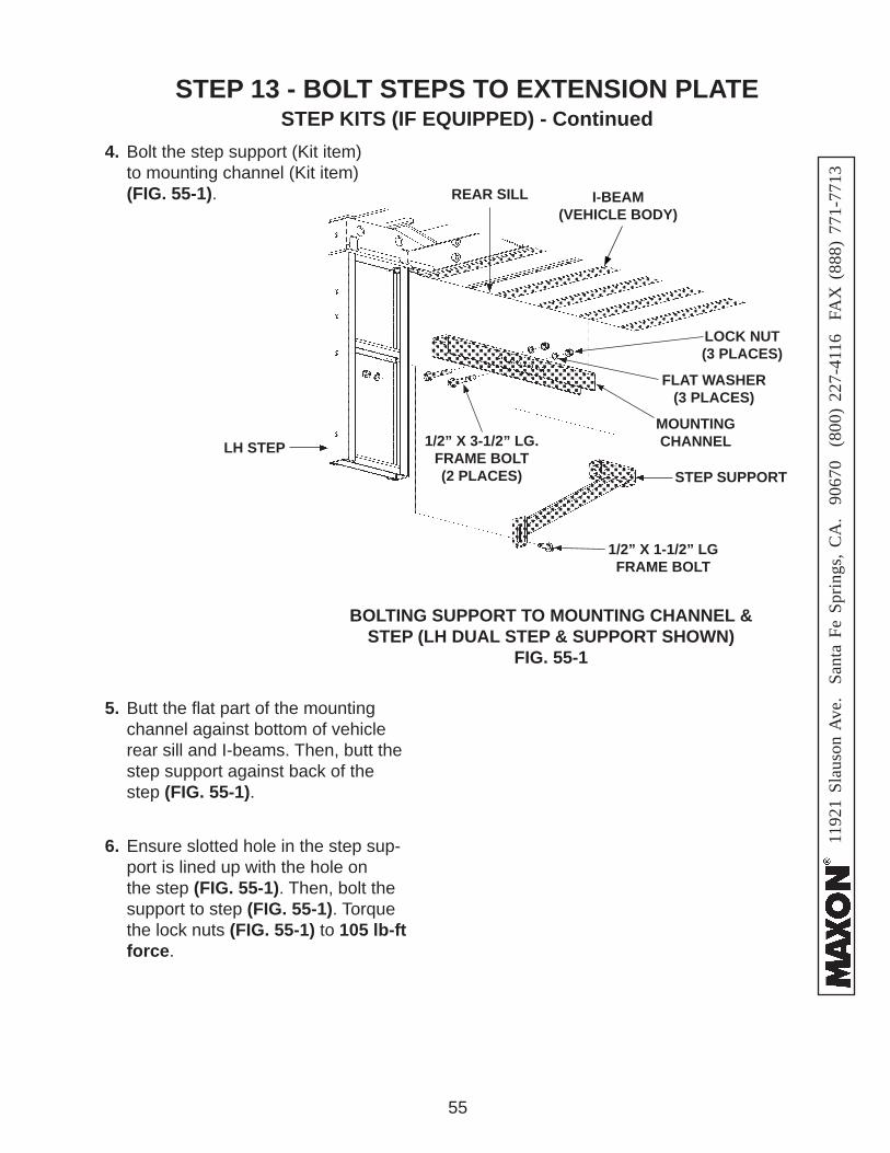
4. Bolt the step support (Kit item) to mounting channel (Kit item) (FIG. 55-1).
BOLTING SUPPORT TO MOUNTING CHANNEL & STEP (LH DUAL STEP & SUPPORT SHOWN)
FIG. 55-1
I-BEAM(VEHICLE BODY)
5. Butt the fl at part of the mounting channel against bottom of vehicle rear sill and I-beams. Then, butt the step support against back of the step (FIG. 55-1).
LH STEP
STEP SUPPORT
MOUNTING CHANNEL
LOCK NUT (3 PLACES)
FLAT WASHER (3 PLACES)
REAR SILL
6. Ensure slotted hole in the step sup-port is lined up with the hole on the step (FIG. 55-1). Then, bolt the support to step (FIG. 55-1). Torque the lock nuts (FIG. 55-1) to 105 lb-ft force.
STEP 13 - BOLT STEPS TO EXTENSION PLATE STEP KITS (IF EQUIPPED) - Continued
1/2” X 3-1/2” LG. FRAME BOLT(2 PLACES)
1/2” X 1-1/2” LG FRAME BOLT
1192
1 Sl
auso
n A
ve.
Sant
a Fe
Spr
ings
, CA
. 90
670
(80
0) 2
27-4
116
FA
X (
888)
771
-771
3
56
WELDING FLAT OF MOUNTING CHANNEL TO VEHICLE BODY (LH DUAL STEP SHOWN)
FIG. 56-1
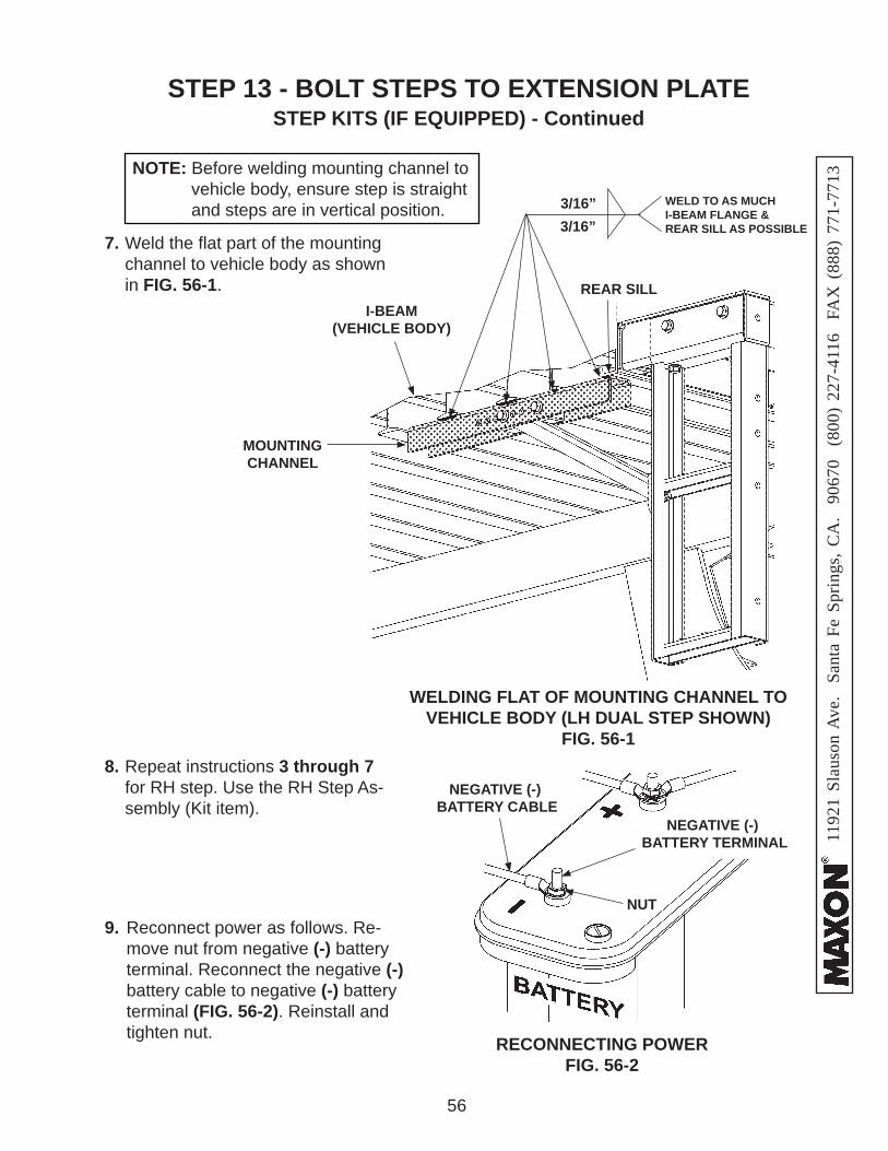
7. Weld the fl at part of the mounting channel to vehicle body as shown in FIG. 56-1.
3/16”
WELD TO AS MUCH I-BEAM FLANGE & REAR SILL AS POSSIBLE
I-BEAM (VEHICLE BODY)
NOTE: Before welding mounting channel to vehicle body, ensure step is straight and steps are in vertical position.
REAR SILL
8. Repeat instructions 3 through 7 for RH step. Use the RH Step As-sembly (Kit item).
9. Reconnect power as follows. Re-move nut from negative (-) battery terminal. Reconnect the negative (-) battery cable to negative (-) battery terminal (FIG. 56-2). Reinstall and tighten nut. RECONNECTING POWER
FIG. 56-2
NEGATIVE (-) BATTERY CABLE
NEGATIVE (-) BATTERY TERMINAL
NUT
STEP 13 - BOLT STEPS TO EXTENSION PLATE STEP KITS (IF EQUIPPED) - Continued
3/16”
MOUNTING CHANNEL

1192
1 Sl
auso
n A
ve.
Sant
a Fe
Spr
ings
, CA
. 90
670
(80
0) 2
27-4
116
FA
X (
888)
771
-771
3
57
Refer to lubrication diagram (FIG. 57-1) to fi nd the lube fi ttings on cylinders and arms. Pump EP chassis grease in each lube fi tting on the cylinders and arms until grease starts oozing from ends of the bearings. Then, wipe off excess grease with a clean lint-free cloth.
STEP 14 - LUBE GREASE FITTINGS (AS NEEDED)
LUBRICATION DIAGRAMFIG. 57-1
NOTE: Lube fi ttings are shown for the RH cylinder, lift arm, and parallel arm. There are also lube fi ttings at the same places on the LH cylinder, lift arm, and parallel arm.
LH CYLINDER,LIFT ARM &PARALLEL ARM
RH CYLINDER,LIFT ARM &PARALLEL ARM
1192
1 Sl
auso
n A
ve.
Sant
a Fe
Spr
ings
, CA
. 90
670
(80
0) 2
27-4
116
FA
X (
888)
771
-771
3
58
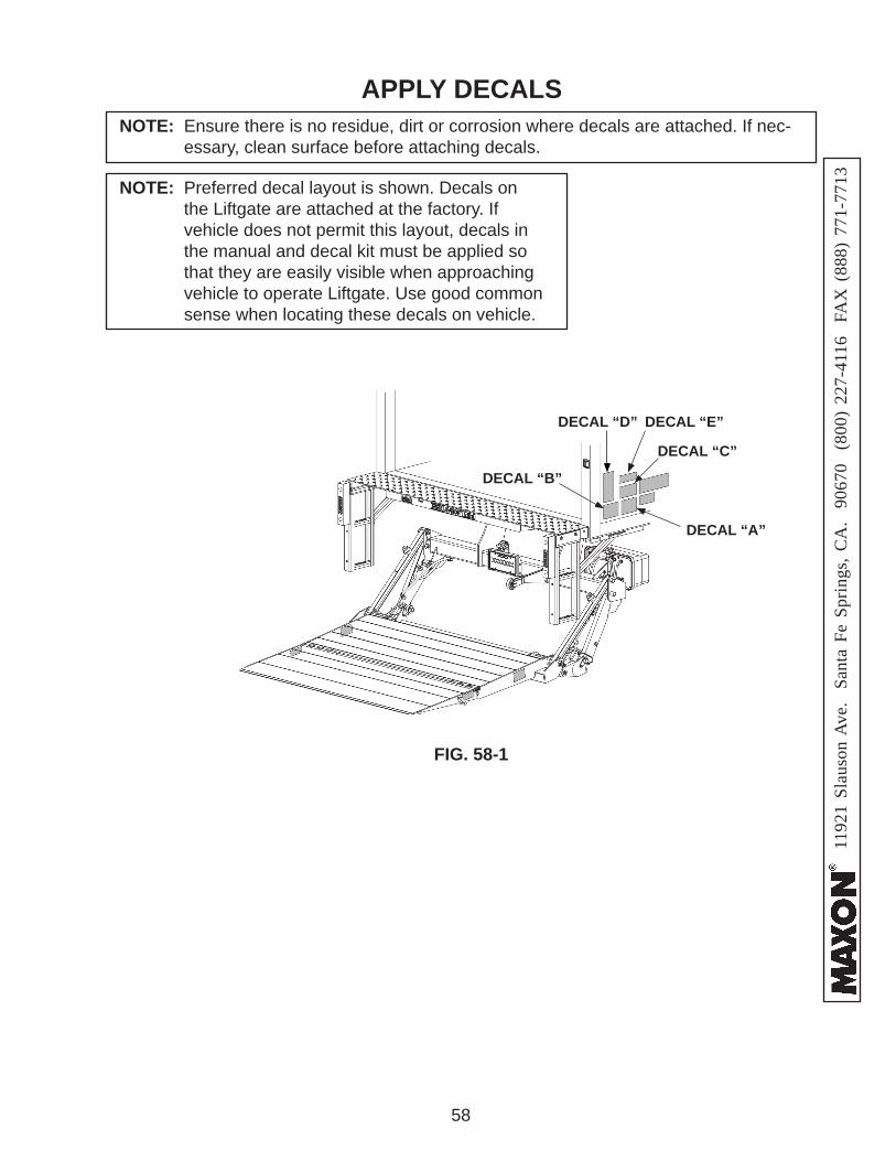
APPLY DECALS
FIG. 58-1
DECAL “A”
DECAL “E”DECAL “D”
DECAL “C”
NOTE: Ensure there is no residue, dirt or corrosion where decals are attached. If nec-essary, clean surface before attaching decals.
NOTE: Preferred decal layout is shown. Decals on the Liftgate are attached at the factory. If vehicle does not permit this layout, decals in the manual and decal kit must be applied so that they are easily visible when approaching vehicle to operate Liftgate. Use good common sense when locating these decals on vehicle.
DECAL “B”
1192
1 Sl
auso
n A
ve.
Sant
a Fe
Spr
ings
, CA
. 90
670
(80
0) 2
27-4
116
FA
X (
888)
771
-771
3
59
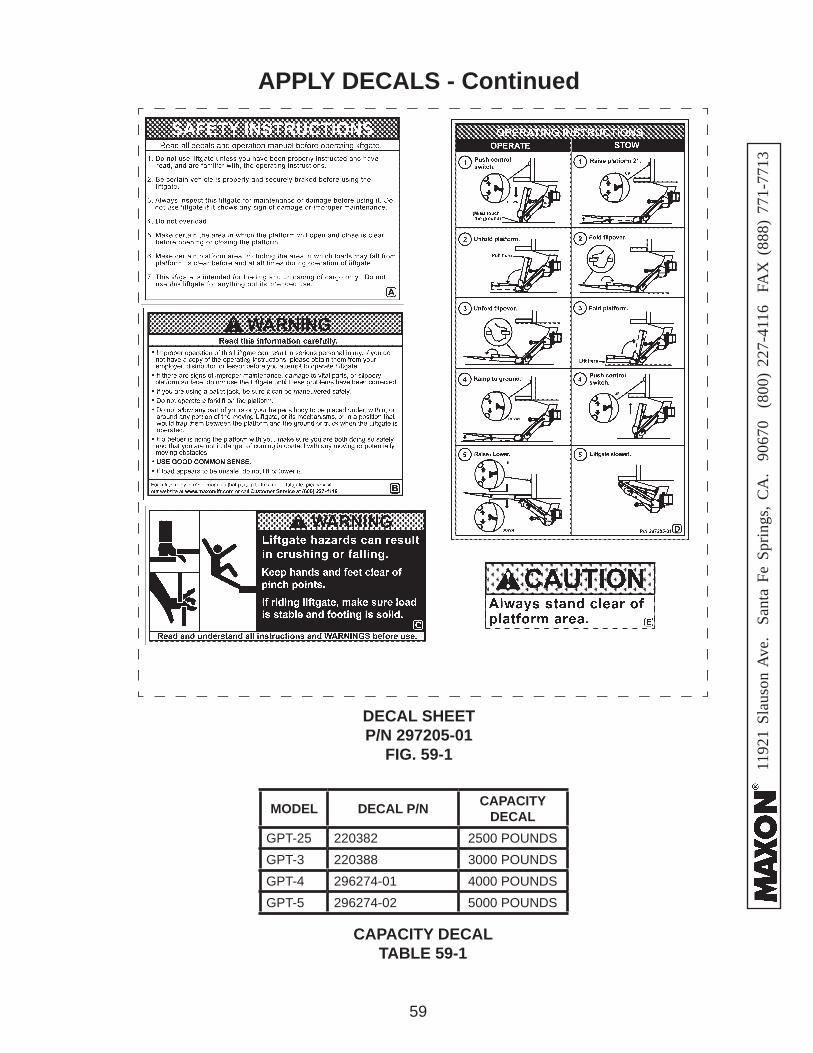
APPLY DECALS - Continued
DECAL SHEET P/N 297205-01
FIG. 59-1
CAPACITY DECALTABLE 59-1
MODEL DECAL P/N CAPACITY DECAL
GPT-25 220382 2500 POUNDSGPT-3 220388 3000 POUNDSGPT-4 296274-01 4000 POUNDSGPT-5 296274-02 5000 POUNDS
1192
1 Sl
auso
n A
ve.
Sant
a Fe
Spr
ings
, CA
. 90
670
(80
0) 2
27-4
116
FA
X (
888)
771
-771
3
60
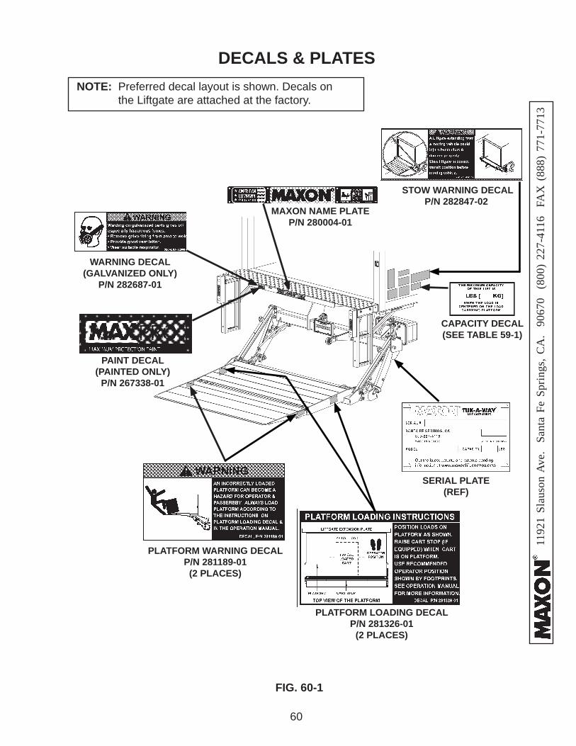
DECALS & PLATES
FIG. 60-1
SERIAL PLATE(REF)
PLATFORM LOADING DECALP/N 281326-01
(2 PLACES)
PLATFORM WARNING DECALP/N 281189-01
(2 PLACES)
PAINT DECAL (PAINTED ONLY)
P/N 267338-01
STOW WARNING DECALP/N 282847-02
NOTE: Preferred decal layout is shown. Decals on the Liftgate are attached at the factory.
MAXON NAME PLATEP/N 280004-01
CAPACITY DECAL(SEE TABLE 59-1)
WARNING DECAL (GALVANIZED ONLY)
P/N 282687-01

1192
1 Sl
auso
n A
ve.
Sant
a Fe
Spr
ings
, CA
. 90
670
(80
0) 2
27-4
116
FA
X (
888)
771
-771
3
61
Damaged cylinder seals and contaminated hydraulic fl uid can result from painting the polished portion of the cylinder rod. To prevent damage, protect the exposed polished portion of the cylinder rod while painting.
CAUTION
TOUCHUP PAINTED OR GALVANIZED FINISH
• If bare metal or primer is exposed on the painted portions of the Liftgate, touch up the paint. To maintain the protection provided by the original paint system, MAXON recom-mends aluminum primer touchup paint kit, P/N 908134-01.
• If bare metal is exposed on galvanized portions of the Liftgate, touch up the galvanized fi nish. To maintain the protection provided by the original galvanized fi nish, MAXON recommends cold galvanize spray.
908134-01
1192
1 Sl
auso
n A
ve.
Sant
a Fe
Spr
ings
, CA
. 90
670
(80
0) 2
27-4
116
FA
X (
888)
771
-771
3
62
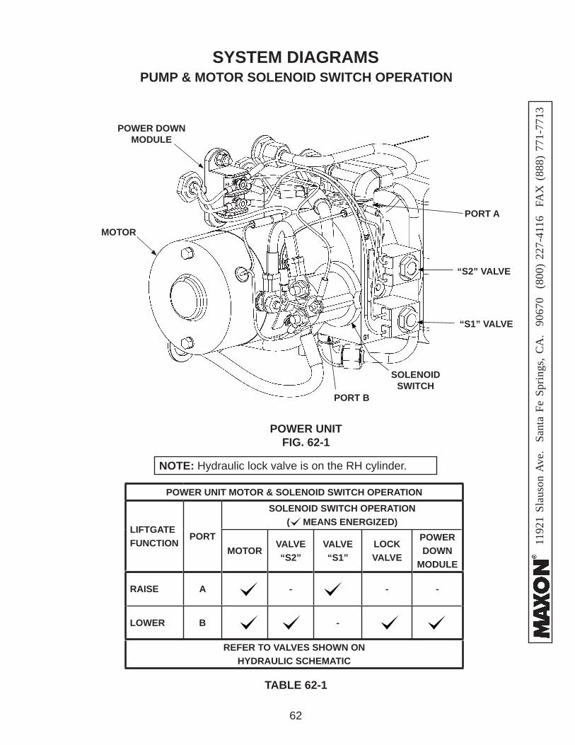
PUMP & MOTOR SOLENOID SWITCH OPERATIONSYSTEM DIAGRAMS
TABLE 62-1
POWER UNITFIG. 62-1
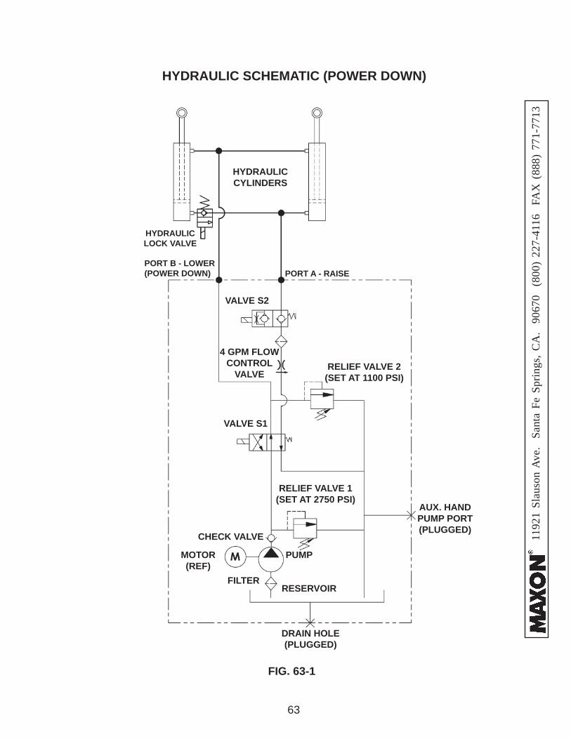
NOTE: Hydraulic lock valve is on the RH cylinder.
SOLENOID SWITCH
“S1” VALVE
“S2” VALVE
MOTOR
PORT B
PORT A
POWER UNIT MOTOR & SOLENOID SWITCH OPERATION
LIFTGATE FUNCTION
PORT
SOLENOID SWITCH OPERATION ( MEANS ENERGIZED)
MOTORVALVE “S2”
VALVE “S1”
LOCK VALVE
POWER DOWN
MODULE
RAISE A - - -
LOWER B -
REFER TO VALVES SHOWN ON HYDRAULIC SCHEMATIC
POWER DOWN MODULE
1192
1 Sl
auso
n A
ve.
Sant
a Fe
Spr
ings
, CA
. 90
670
(80
0) 2
27-4
116
FA
X (
888)
771
-771
3
63
HYDRAULIC SCHEMATIC (POWER DOWN)
FIG. 63-1
PORT B - LOWER (POWER DOWN) PORT A - RAISE
RELIEF VALVE 2(SET AT 1100 PSI)
PUMP
AUX. HANDPUMP PORT (PLUGGED)
VALVE S2
VALVE S1
HYDRAULICCYLINDERS
4 GPM FLOW CONTROL
VALVE
RESERVOIR
DRAIN HOLE(PLUGGED)
FILTER
MOTOR(REF)
RELIEF VALVE 1(SET AT 2750 PSI)
HYDRAULIC LOCK VALVE
CHECK VALVE
1192
1 Sl
auso
n A
ve.
Sant
a Fe
Spr
ings
, CA
. 90
670
(80
0) 2
27-4
116
FA
X (
888)
771
-771
3
64
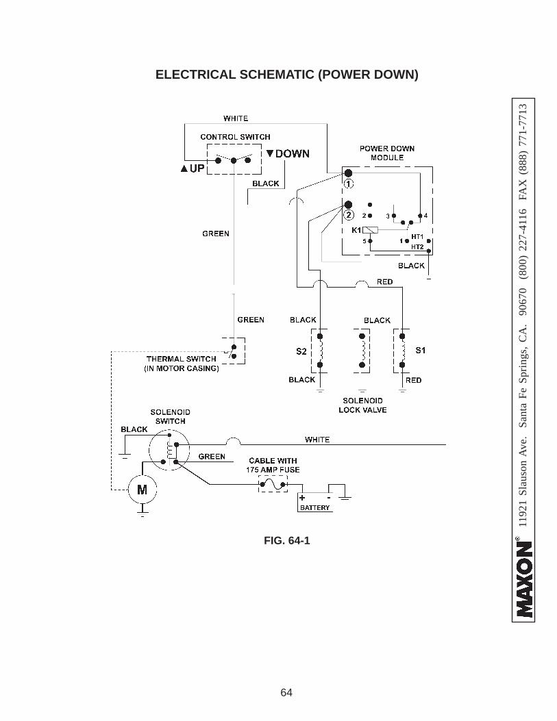
ELECTRICAL SCHEMATIC (POWER DOWN)
FIG. 64-1
1192
1 Sl
auso
n A
ve.
Sant
a Fe
Spr
ings
, CA
. 90
670
(80
0) 2
27-4
116
FA
X (
888)
771
-771
3
65
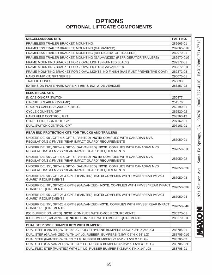
OPTIONAL LIFTGATE COMPONENTSOPTIONS
MISCELLANEOUS KITS PART NO.FRAMELESS TRAILER BRACKET, MOUNTING 282665-01FRAMELESS TRAILER BRACKET, MOUNTING (GALVANIZED) 282665-01GFRAMELESS TRAILER BRACKET, MOUNTING (REFRIGERATOR TRAILERS) 282970-01FRAMELESS TRAILER BRACKET, MOUNTING (GALVANIZED) (REFRIGERATOR TRAILERS) 282970-01GFRAME MOUNTING BRACKET FOR 2 OVAL LIGHTS (PAINTED BLACK) 282372-01FRAME MOUNTING BRACKET FOR 2 OVAL LIGHTS (GALVANIZED) 282372-01GFRAME MOUNTING BRACKET FOR 2 OVAL LIGHTS, NO FINISH (HAS RUST PREVENTIVE COAT) 282372-03HAND PUMP KIT, GPT SERIES 296075-01TRAFFIC CONES 268893EXTENSION PLATE HARDWARE KIT (96” & 102” WIDE VEHICLE) 283257-02
ELECTRICAL KITSIN CAB ON-OFF SWITCH 250477CIRCUIT BREAKER (150 AMP) 251576GROUND CABLE, 2 GAUGE X 38’ LG. 269190-01CYCLE COUNTER, GPT 282520-02HAND HELD CONTROL, GPT 263260-12STREET SIDE CONTROL, GPT 297162-01DUAL SWITCH CONTROL, GPT 297161-01
REAR END PROTECTION KITS FOR TRUCKS AND TRAILERSUNDERRIDE, 90", GPT-4 & GPT-5 (PAINTED) NOTE: COMPLIES WITH CANADIAN MVS REGULATIONS & FMVSS “REAR IMPACT GUARD” REQUIREMENTS 287050-01
UNDERRIDE, 90", GPT-4 & GPT-5 (GALVANIZED) NOTE: COMPLIES WITH CANADIAN MVS REGULATIONS & FMVSS “REAR IMPACT GUARD” REQUIREMENTS 287050-01G
UNDERRIDE, 95", GPT-4 & GPT-5 (PAINTED) NOTE: COMPLIES WITH CANADIAN MVS REGULATIONS & FMVSS “REAR IMPACT GUARD” REQUIREMENTS 287050-02
UNDERRIDE, 95", GPT-4 & GPT-5 (GALVANIZED) NOTE: COMPLIES WITH CANADIAN MVS REGULATIONS & FMVSS “REAR IMPACT GUARD” REQUIREMENTS 287050-02G
UNDERRIDE, 90", GPT-25 & GPT-3 (PAINTED) NOTE: COMPLIES WITH FMVSS “REAR IMPACT GUARD” REQUIREMENTS 287050-03
UNDERRIDE, 90", GPT-25 & GPT-3 (GALVANIZED) NOTE: COMPLIES WITH FMVSS “REAR IMPACT GUARD” REQUIREMENTS 287050-03G
UNDERRIDE, 95", GPT-25 & GPT-3 (PAINTED) NOTE: COMPLIES WITH FMVSS “REAR IMPACT GUARD” REQUIREMENTS 287050-04
UNDERRIDE, 95", GPT-25 & GPT-3 (GALVANIZED) NOTE: COMPLIES WITH FMVSS “REAR IMPACT GUARD” REQUIREMENTS 287050-04G
ICC BUMPER (PAINTED) NOTE: COMPLIES WITH OMCS REQUIREMENTS 283270-01ICC BUMPER (GALVANIZED) NOTE: COMPLIES WITH OMCS REQUIREMENTS 283270-01G
DUAL STEP DOCK BUMPER KITS WITH BUMPERSDUAL STEP (PAINTED) WITH 14” LG. POLYETHYLENE BUMPERS (2.5W X 3”H X 24” LG) 288705-01DUAL STEP (GALVANIZED) WITH 14” LG. RUBBER BUMPERS (2.5W X 3”H X 24” LG) 288705-01GDUAL STEP (PAINTED) WITH 13.5” LG. RUBBER BUMPERS (2.9”W X 1.5”H X 14”LG) 288705-02DUAL STEP (GALVANIZED) WITH 13.5” LG. RUBBER BUMPERS (2.9”W X 1.5”H X 14”LG) 288705-02GDUAL FLEX STEP (PAINTED) WITH 14” LG. RUBBER BUMPERS (2.5W X 3”H X 14” LG) 288705-21
1192
1 Sl
auso
n A
ve.
Sant
a Fe
Spr
ings
, CA
. 90
670
(80
0) 2
27-4
116
FA
X (
888)
771
-771
3
66
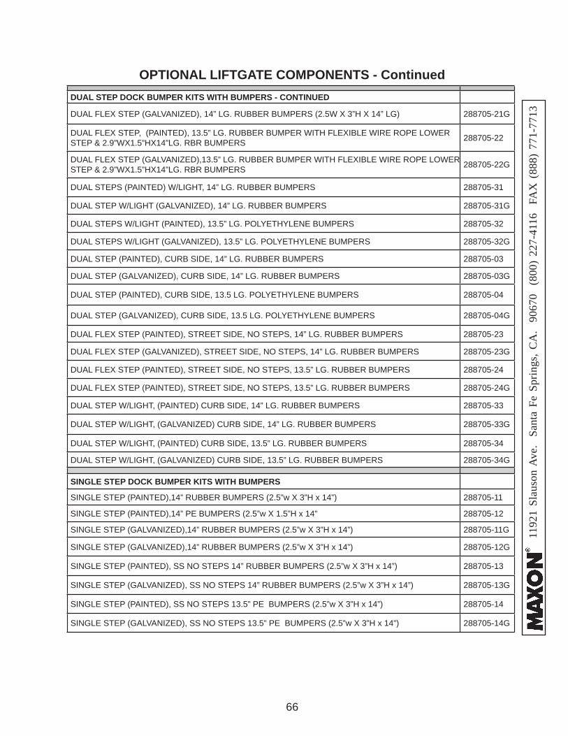
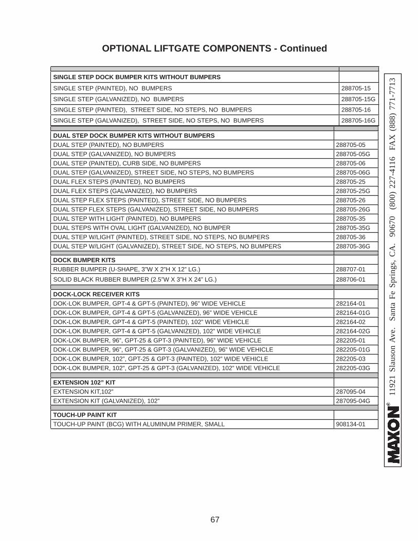
OPTIONAL LIFTGATE COMPONENTS - ContinuedDUAL STEP DOCK BUMPER KITS WITH BUMPERS - CONTINUED
DUAL FLEX STEP (GALVANIZED), 14” LG. RUBBER BUMPERS (2.5W X 3”H X 14” LG) 288705-21G
DUAL FLEX STEP, (PAINTED), 13.5” LG. RUBBER BUMPER WITH FLEXIBLE WIRE ROPE LOWER STEP & 2.9”WX1.5”HX14”LG. RBR BUMPERS 288705-22
DUAL FLEX STEP (GALVANIZED),13.5” LG. RUBBER BUMPER WITH FLEXIBLE WIRE ROPE LOWER STEP & 2.9”WX1.5”HX14”LG. RBR BUMPERS 288705-22G
DUAL STEPS (PAINTED) W/LIGHT, 14” LG. RUBBER BUMPERS 288705-31
DUAL STEP W/LIGHT (GALVANIZED), 14” LG. RUBBER BUMPERS 288705-31G
DUAL STEPS W/LIGHT (PAINTED), 13.5” LG. POLYETHYLENE BUMPERS 288705-32
DUAL STEPS W/LIGHT (GALVANIZED), 13.5” LG. POLYETHYLENE BUMPERS 288705-32G
DUAL STEP (PAINTED), CURB SIDE, 14” LG. RUBBER BUMPERS 288705-03
DUAL STEP (GALVANIZED), CURB SIDE, 14” LG. RUBBER BUMPERS 288705-03G
DUAL STEP (PAINTED), CURB SIDE, 13.5 LG. POLYETHYLENE BUMPERS 288705-04
DUAL STEP (GALVANIZED), CURB SIDE, 13.5 LG. POLYETHYLENE BUMPERS 288705-04G
DUAL FLEX STEP (PAINTED), STREET SIDE, NO STEPS, 14” LG. RUBBER BUMPERS 288705-23
DUAL FLEX STEP (GALVANIZED), STREET SIDE, NO STEPS, 14” LG. RUBBER BUMPERS 288705-23G
DUAL FLEX STEP (PAINTED), STREET SIDE, NO STEPS, 13.5” LG. RUBBER BUMPERS 288705-24
DUAL FLEX STEP (PAINTED), STREET SIDE, NO STEPS, 13.5” LG. RUBBER BUMPERS 288705-24G
DUAL STEP W/LIGHT, (PAINTED) CURB SIDE, 14” LG. RUBBER BUMPERS 288705-33
DUAL STEP W/LIGHT, (GALVANIZED) CURB SIDE, 14” LG. RUBBER BUMPERS 288705-33G
DUAL STEP W/LIGHT, (PAINTED) CURB SIDE, 13.5” LG. RUBBER BUMPERS 288705-34
DUAL STEP W/LIGHT, (GALVANIZED) CURB SIDE, 13.5” LG. RUBBER BUMPERS 288705-34G
SINGLE STEP DOCK BUMPER KITS WITH BUMPERS
SINGLE STEP (PAINTED),14” RUBBER BUMPERS (2.5”w X 3”H x 14”) 288705-11
SINGLE STEP (PAINTED),14” PE BUMPERS (2.5”w X 1.5”H x 14” 288705-12
SINGLE STEP (GALVANIZED),14” RUBBER BUMPERS (2.5”w X 3”H x 14”) 288705-11G
SINGLE STEP (GALVANIZED),14” RUBBER BUMPERS (2.5”w X 3”H x 14”) 288705-12G
SINGLE STEP (PAINTED), SS NO STEPS 14” RUBBER BUMPERS (2.5”w X 3”H x 14”) 288705-13
SINGLE STEP (GALVANIZED), SS NO STEPS 14” RUBBER BUMPERS (2.5”w X 3”H x 14”) 288705-13G
SINGLE STEP (PAINTED), SS NO STEPS 13.5” PE BUMPERS (2.5”w X 3”H x 14”) 288705-14
SINGLE STEP (GALVANIZED), SS NO STEPS 13.5” PE BUMPERS (2.5”w X 3”H x 14”) 288705-14G
1192
1 Sl
auso
n A
ve.
Sant
a Fe
Spr
ings
, CA
. 90
670
(80
0) 2
27-4
116
FA
X (
888)
771
-771
3
67
OPTIONAL LIFTGATE COMPONENTS - Continued
DUAL STEP DOCK BUMPER KITS WITHOUT BUMPERSDUAL STEP (PAINTED), NO BUMPERS 288705-05DUAL STEP (GALVANIZED), NO BUMPERS 288705-05GDUAL STEP (PAINTED), CURB SIDE, NO BUMPERS 288705-06DUAL STEP (GALVANIZED), STREET SIDE, NO STEPS, NO BUMPERS 288705-06GDUAL FLEX STEPS (PAINTED), NO BUMPERS 288705-25DUAL FLEX STEPS (GALVANIZED), NO BUMPERS 288705-25GDUAL STEP FLEX STEPS (PAINTED), STREET SIDE, NO BUMPERS 288705-26DUAL STEP FLEX STEPS (GALVANIZED), STREET SIDE, NO BUMPERS 288705-26GDUAL STEP WITH LIGHT (PAINTED), NO BUMPERS 288705-35DUAL STEPS WITH OVAL LIGHT (GALVANIZED), NO BUMPER 288705-35GDUAL STEP W/LIGHT (PAINTED), STREET SIDE, NO STEPS, NO BUMPERS 288705-36DUAL STEP W/LIGHT (GALVANIZED), STREET SIDE, NO STEPS, NO BUMPERS 288705-36G
DOCK BUMPER KITSRUBBER BUMPER (U-SHAPE, 3”W X 2”H X 12” LG.) 288707-01SOLID BLACK RUBBER BUMPER (2.5”W X 3”H X 24” LG.) 288706-01
DOCK-LOCK RECEIVER KITSDOK-LOK BUMPER, GPT-4 & GPT-5 (PAINTED), 96” WIDE VEHICLE 282164-01DOK-LOK BUMPER, GPT-4 & GPT-5 (GALVANIZED), 96” WIDE VEHICLE 282164-01GDOK-LOK BUMPER, GPT-4 & GPT-5 (PAINTED), 102” WIDE VEHICLE 282164-02DOK-LOK BUMPER, GPT-4 & GPT-5 (GALVANIZED), 102” WIDE VEHICLE 282164-02GDOK-LOK BUMPER, 96”, GPT-25 & GPT-3 (PAINTED), 96” WIDE VEHICLE 282205-01DOK-LOK BUMPER, 96”, GPT-25 & GPT-3 (GALVANIZED), 96” WIDE VEHICLE 282205-01GDOK-LOK BUMPER, 102”, GPT-25 & GPT-3 (PAINTED), 102” WIDE VEHICLE 282205-03DOK-LOK BUMPER, 102”, GPT-25 & GPT-3 (GALVANIZED), 102” WIDE VEHICLE 282205-03G
EXTENSION 102” KITEXTENSION KIT,102” 287095-04EXTENSION KIT (GALVANIZED), 102” 287095-04G
TOUCH-UP PAINT KITTOUCH-UP PAINT (BCG) WITH ALUMINUM PRIMER, SMALL 908134-01
SINGLE STEP DOCK BUMPER KITS WITHOUT BUMPERS
SINGLE STEP (PAINTED), NO BUMPERS 288705-15
SINGLE STEP (GALVANIZED), NO BUMPERS 288705-15G
SINGLE STEP (PAINTED), STREET SIDE, NO STEPS, NO BUMPERS 288705-16
SINGLE STEP (GALVANIZED), STREET SIDE, NO STEPS, NO BUMPERS 288705-16G