Installation Manual IM1253-1 - Daikin Applied
32
Installation Manual IM1253-1 Group: Controls Part Number: IM 1253 Date: February 2017 Daikin System Manager Use with Daikin Intelligent Systems ™
Transcript of Installation Manual IM1253-1 - Daikin Applied

Installation Manual IM1253-1Group: ControlsPart Number: IM 1253Date: February 2017
Daikin System Manager
Use with Daikin Intelligent Systems™

IM1253-1 • INTELLIGENT SYSTEM MANAGER 2 www.DaikinApplied.com
Table of ConTenTs
Table of ConTenTs
Revision History . . . . . . . . . . . . . . . . . . . . . . . . . . . . . 2Reference Documents . . . . . . . . . . . . . . . . . . . . . . . . 2
Introduction . . . . . . . . . . . . . . . . . . . . . . . . . . . . . . . . . . 3Limited Warranty . . . . . . . . . . . . . . . . . . . . . . . . . . . . . 3General Information . . . . . . . . . . . . . . . . . . . . . . . . . . 3Hazardous Information Messages . . . . . . . . . . . . . . . 3Installer Responsibilities . . . . . . . . . . . . . . . . . . . . . . . 3Receiving Inspection . . . . . . . . . . . . . . . . . . . . . . . . . . 3
Communication Network Wiring . . . . . . . . . . . . . . . . . 4Avoid Signal Noise. . . . . . . . . . . . . . . . . . . . . . . . . . 6
Control Panel (System Manager) . . . . . . . . . . . . . . . . 7All Units . . . . . . . . . . . . . . . . . . . . . . . . . . . . . . . . . . 7System Manager Calibration . . . . . . . . . . . . . . . . . . 7
System Manager Shut Down/Restart . . . . . . . . . . . . . 8Shut down . . . . . . . . . . . . . . . . . . . . . . . . . . . . . . . . . . 8Restart. . . . . . . . . . . . . . . . . . . . . . . . . . . . . . . . . . . . . 8
Windows Features . . . . . . . . . . . . . . . . . . . . . . . . . . . . 9On-Screen Keyboard . . . . . . . . . . . . . . . . . . . . . . . . . 9Updating Local Time . . . . . . . . . . . . . . . . . . . . . . . . . . 9Disabling Windows Firewall . . . . . . . . . . . . . . . . . . . 10Windows Update . . . . . . . . . . . . . . . . . . . . . . . . . . . . 10
Networking . . . . . . . . . . . . . . . . . . . . . . . . . . . . . . . . . 11Determining IP Address and Subnet Mask . . . . . . . . 11Setting Manual IP Address and Subnet Mask. . . . . . 12
Startup . . . . . . . . . . . . . . . . . . . . . . . . . . . . . . . . . . . . . 13Discovery Mode . . . . . . . . . . . . . . . . . . . . . . . . . . . . 13Service Utilities – Global Actions. . . . . . . . . . . . . . . . 13Service Utilities - Balancing. . . . . . . . . . . . . . . . . . . . 13Service Utilities – Network Actions . . . . . . . . . . . . . . 14
ATS Auto Assignment. . . . . . . . . . . . . . . . . . . . . . . 14WCIS Software Tool for VAVs . . . . . . . . . . . . . . . . . . 14
Scheduling . . . . . . . . . . . . . . . . . . . . . . . . . . . . . . . . . 16Creating Schedules. . . . . . . . . . . . . . . . . . . . . . . . . . 16Giving Devices a Schedule . . . . . . . . . . . . . . . . . . . . 16Adding Users. . . . . . . . . . . . . . . . . . . . . . . . . . . . . . . 17Saving the Configuration . . . . . . . . . . . . . . . . . . . . . . 19System Manager Back Plate Connections . . . . . . . . 20
LED Indicators . . . . . . . . . . . . . . . . . . . . . . . . . . . . 20MS/TP Network Connector . . . . . . . . . . . . . . . . . . 20LAN 1/LAN 2 & USB . . . . . . . . . . . . . . . . . . . . . . . 20VGA & HDMI . . . . . . . . . . . . . . . . . . . . . . . . . . . . . 20Power Connection (PWR) . . . . . . . . . . . . . . . . . . . 20Headphone & Microphone Jack. . . . . . . . . . . . . . . 20
Troubleshooting . . . . . . . . . . . . . . . . . . . . . . . . . . . . . 21Event Log Troubleshooting . . . . . . . . . . . . . . . . . . . . 22
Troubleshooting . . . . . . . . . . . . . . . . . . . . . . . . . . . . . 23Warranty Registration Form . . . . . . . . . . . . . . . . . . . 27Quality Assurance Survey Form . . . . . . . . . . . . . . 31
Revision HistoryVersion Number Date Comment
IM 1253-1 February, 2017 Name Change
IM 1253 March, 2016 Initial Release
Reference DocumentsLiterature Number Company Title Source
OM 1254
Daikin Applied
Daikin System Manager
DaikinApplied.com
IOM 1135 MicroTech III Generic I/O Manager
IOM 1150 LWM Installation and Operation Manual
OM 920 MicroTech III Operation Manual for Rooftop units
OM 931 MicroTech III Unit Controller for WSHP Units
OM 1063 BACnet VAV Actuator Owner’s Manual
ED 15112Protocol Information for MicroTech III Rooftop and Self-Contained Units
ED 19013MicroTech III Generic I/O Unit Controller Protocol Implementation Conformance Statement (PICS)
ED 19014 MicroTech III Generic I/O Unit Controller Protocol Information
ED 19015 LWM PICS and Protocol Information
ED 19069 Technical Specification SheetIM 1255 Quick Installation Guide

InTroduCTIon
www.DaikinApplied.com 3 IM1253-1 • INTELLIGENT SYSTEM MANAGER
InTroduCTIon
Limited WarrantyConsult your local Daikin Applied representative for warranty details. To find your local Daikin Applied representative, go to www.DaikinApplied.com
General InformationThis manual provides general information about the Intelligent System Manager. In addition to an overall description of the unit, it includes mechanical and electrical installation procedures.
The System Manager is in a headless encasement accompanied by a touch screen. For a detailed description of the operation of the System Manager refer to OM 1254
The System Manager consists of a web-based user interface (Web-like pages accessible with Chrome) which allows the user to edit control parameters required for control of the Intelligent Systems. It is a Windows® Embedded Standard 7 with Ethernet Card and TCP/IP Protocol, Chrome browser, and Ethernet Cable access to network.
Hazardous Information Messages CAUTION
Cautions indicate potentially hazardous situations, which can result in personal injury or equipment damage if not avoided.
WARNINGWarnings indicate potentially hazardous situations, which can result in property damage, severe personal injury, or death if not avoided.
DANGERDangers indicate a hazardous situation which will result in death or serious injury if not avoided.
NOTICENotices give important information concerning a process, procedure, special handling or equipment attributes.
CAUTIONStatic sensitive components . Can cause equipment damage .Discharge any static electrical charge by touching the bare metal inside the control panel before performing any service work. Never unplug cables, circuit board terminal blocks, or power plugs while power is applied to the Manager.
Installer ResponsibilitiesThe installation of this equipment shall be in accordance with the regulations of authorities having jurisdiction and all applicable codes. It is the responsibility of the installer to determine and follow the applicable codes.
Receiving InspectionWhen the device is received, all items should be carefully checked against the bill of lading to be sure all packages have been received.
Inspect the System Manager for any shipping damage. Report all shipping damage to the carrier and file a claim.
Included Items:
A. System Manager
B. 15.6" touch screen monitor
C. System Manager display bracket
D. 4 × screws and 4 × 10mm standoffs for VESA mounting
E. Cables – VGA male to male plug, USB type A to type B
F. 120AC-12VDC adapter with screw lug power connector
**Wall-mounting screws and anchors are not included
Required Tools:
• Screwdriver• Controls screwdrivers
Optional Jobsite Tools:
• Laptop• USB storage device• USB keyboard• USB mouse• Ethernet crossover cable• Voltmeter• Nut driver• WCIS Cable – P/N 250804701• Network wiring map• OM 1254
Intelligent System Manager
250801500
A BC
DE
F

IM1253-1 • INTELLIGENT SYSTEM MANAGER 4 www.DaikinApplied.com
CommunICaTIon neTwork wIrIng
CommunICaTIon neTwork wIrIng
Communication wires to all devices on the network, including the System Manager, shall be installed per standard BACnet MS/TP wiring guidelines. All devices in the network shall be Daisy-Chained in any order using 22 AWG twisted pair stranded shielded wire. For lengths over 4000 feet a repeater shall be used, however minimize wire length when possible. Do not “Star” or “T” the network wire. See Figure 1 for a detailed diagram. It is recommended to trace the wiring network on the building layout and upload to the System Manager and to keep a copy for your records.
Figure 1: Intelligent Systems Field Wiring Details

CommunICaTIon neTwork wIrIng
www.DaikinApplied.com 5 IM1253-1 • INTELLIGENT SYSTEM MANAGER
To properly connect the communication wires to the appropriate terminal block follow these steps:
1. Cut off 1 inch of the outer jacket of the cable, being cautious to not nick the inner insulation.
2. For each inner wire strip off 0.25 inches of the insulation.
3. Ensure the polarity (+/-) for each conductor is maintained throughout all devices.
4. When wiring two cables to the controller, twist together the shield wires from both cables and secure with a wire nut, shown in Figure 2. Twist the wire nut in the same direction the wires were twisted together. Land shield to earth ground at ONE END ONLY to prevent ground currents from being created as seen in Figure 4. Ensure that the shield wire does not ground against the case .
5. Insert the wires into the appropriate terminal block. The bare communication wire shall not extend beyond 0.125 inches, shown in Figure 3.
Figure 2: Twisted Pair Wiring with The Shields Twisted Together. Use a Wire-Nut on the Shield Connection
Figure 3: Communication Wires Inserted into Terminal Block
NOTE: If bare communication wire contacts the cable’s foil shield, shield wire, or a metal surface other than the terminal block, communications may fail.
In Figure 4 all of the non-isolated devices use two-wire connections with the reference level between devices established by an internal earth ground connection made through some impedance (Z) at each device. This is generally the lowest cost solution and is sufficient for installations where electrical noise, ground noise, and stray fields are low. EIA-485 is designed to operate with voltages on the signaling wires between -7 and +12 volts.
Figure 4: Twisted Pair Wiring with Devices and Shield Grounded at One Location
A 120 ohm end of line (EOL) resister, also known as a termination resistor, is required on both ends, as seen in Figure 5. This will reduce bounce back interference when the MS/TP token gets to the end of the trunk. If a MicroTech III controller is EOL, an internal EOL resistor can be enabled, however if this unit needs to be powered down for maintenance, the software EOL resistor will no longer be applied. Therefore, it is highly recommended to use a physical EOL resistor.
Figure 5: Wiring at EOL Device. Only Ground Shield at One Location

IM1253-1 • INTELLIGENT SYSTEM MANAGER 6 www.DaikinApplied.com
CommunICaTIon neTwork wIrIng
Hardware improvements include bias resistors built into the System Manager. NOTE: The older version of the System Manager required
the installation of bias resistors.
Up to one additional set of bias resistors (510Ω ± 5%) may be added if desired. Refer to Figure 6 for wiring details.
Avoid Signal NoiseFor best communication avoid running communication wires or sensor input wires next to AC power wires, VFDs, or the controller’s relay output wires. These can be sources of noise that can affect signal quality. Devices that could cause noise are:
• Spark igniters• Radio transmitter• VFD• Electric motor > 1 hp• Generator• Relays• Transformers• Induction heaters• Large conductors• Video display devices
Figure 6: Bias Resistors and EOL Resistors on Network

CommunICaTIon neTwork wIrIng
www.DaikinApplied.com 7 IM1253-1 • INTELLIGENT SYSTEM MANAGER
Control Panel (System Manager)The System Manager shall be located in a conditioned space that is easily accessible. Allow for space around the System Manager for air flow circulation, this is needed for rejection of heat. It is recommended to install surge protection and an uninterruptible power supply (UPS) to protect the System Manager from a hard shutdown due to building power failure.
The VESA mounts on the display bracket allows the System Manager to be attached to the back of the monitor via VESA mounting screws. The display bracket can also be mounted on a wall, with the monitor attached to the front, see Figure 7.
1. Fasten the display bracket to the back of the monitor using the screws.
2. Fasten wall mounting screws and anchors into a wall, leaving space to attach the display bracket. Slide the display bracket mounting holes onto the screws and fasten. It is recommended that at least one screw should be mounted in a wall stud.
NOTE: The wall mounting screws and anchors are not included.
3. Slide the System Manager into the display bracket, the rubber feet should be facing away from the monitor.
4. Connect cables.
a. VGA – System Manager to Monitor
b. USB – System Manager to touch screen Monitor
c. (2) Power Supply – Barrel Screw Connector to System Manager and touchscreen monitor
5. Connect the BACnet MS/TP twisted pair wire to the BACnet MS/TP terminal maintaining polarity throughout the daisy-chain, refer to Figure 8 and Figure 9.
6. The Intelligent Systems automatically starts when the System Manager has power and the BACnet MS/TP network is run appropriately. Refer to OM 1254 for user operation.
Figure 7: System Manager Vesa Mounted on the Touch Screen Monitor (monitor stand not included)
Figure 8: Wiring to the System Manager
If the System Manager is at the end of the network, a 120 Ω resistor should be inserted into the terminal in addition to the twisted pair.
Figure 9: Rear Plate of System Manager
All UnitsAll units must be installed and started up per their Installation Manuals. Duct and building pressure tubing shall be run to pressure transducers per unit Installation Manual. VAV units shall be installed per their Installation Manual in the proper location. All VAV controllers shall have their space sensor wired with the provided cat3 cable. WSHP and Fan Coil Units shall be installed per their Installation Manual in the proper location.
System Manager CalibrationTo ensure a judicious mode of operation, the System Manager should be calibrated. Tap on the top of the screen and a window saying “You have gone full screen. Press F11 to exit full screen.” Press “Press F11 to exit full screen” and minimize chrome in the upper right corner. Go into the start menu by pressing at the extreme bottom of the screen, or by moving a mouse down to the bottom of the screen. “Search Programs and Files” and type “Calibrate the screen for pen or touch input”. Select “Calibrate the screen for pen or touch input”. A window shown in Figure 10 should appear. Select “Calibrate…” and a screen with some border lines will appear. Tab the crosshairs as they appear in each corner to complete calibration.
Figure 10: Configuration

IM1253-1 • INTELLIGENT SYSTEM MANAGER 8 www.DaikinApplied.com
sysTem manager shuT down/resTarT
sysTem manager shuT down/resTarT
Shut downThe System Manager can be shut down safely using the shutdown button located in the left hand menu bar on the main screen, shown in Figure 11. This button is available if accessing the controller remotely only to commission level, but is available to all user levels locally at the System Manager. Do not power down using the power cord . The System Manager can also be shutdown using the power switch located on the controller itself.
Restart CAUTION
Not following the proper shut down methods can result in corruption to the System Manager database
The System Manager can be restarted safely using the restart button located in the left hand menu bar on the main screen, shown in Figure 11. This button is available if accessing the controller remotely only to commission level, but is available to all user levels locally at the System Manager. Do not restart using the power cord . The system may also be restarted or shutdown remotely at Commission access level.
Figure 11: System Shutdown and Restart Buttons

wIndows feaTures
www.DaikinApplied.com 9 IM1253-1 • INTELLIGENT SYSTEM MANAGER
wIndows feaTures
The System Manager is a Windows® Embedded Standard 7 computer that has a few features to change and update for installation.
On-Screen KeyboardWindows Embedded Standard 7 has an on-screen keyboard application that can be used instead of a USB keyboard. This keyboard is used when needing to type outside of the Intelligent Systems application. To open the on-screen keyboard select the tab along the left side of the screen, shown in Figure 12. The on-screen keyboard, Figure 13, will appear.
Figure 12: On-Screen Keyboard Tab
Figure 13: On-Screen Keyboard
To type within the System Manager, you may either use the embedded keyboard as shown above, or use the built-in virtual keyboard through the System Manager. By selecting the keyboard icon next to the small alarm notification icon in the top right corner, a notification saying “virtual keyboard enabled” or “virtual keyboard disabled” will appear. If it is enabled, the icon will be lit up, and whenever an interactive text box is selected, the virtual keyboard will appear.
Updating Local Time NOTICE
You must restart the Intelligent Systems for Time/Date changes to apply.
To avoid problems with following scheduling plans, it’s necessary to update the Time and Time Zone of your System Manager.
Tap on the top of the screen and a window saying “You have gone full screen. Press F11 to exit full screen.” Press “Press F11 to exit full screen” and minimize chrome in the upper right corner. Tap at the extreme bottom of the screen. Go to your system clock, which you will find on the bottom right corner of the desktop, double press on the Date/Time to open the properties window, Figure 14. Use this window to adjust your system time. Update the Time Zone if necessary as seen in Figure 15. The Intelligent Systems application needs to be restarted for the changes to apply. Go to the Home screen and select Restart.
Figure 14: Date and Time Properties
Figure 15: Time Zone Settings

IM1253-1 • INTELLIGENT SYSTEM MANAGER 10 www.DaikinApplied.com
wIndows feaTures
Disabling Windows FirewallTo avoid network complications when viewing the system remotely, the Windows firewall needs to be either configured or disabled on the System Manager. To configure the firewall, navigate to the start menu. From the start menu, select the search box “Search Programs and Files” and type “Windows Firewall”. Next select “Windows Firewall”. Then click on the “Turn Windows Firewall ON or OFF” link on the left side menu. Select the “OFF” option to disable Windows Firewall. The other option is to navigate to “Windows Firewall with Advanced Security” where configuration options are available under “Windows Firewall Properties”. Click OK to apply new firewall settings.
Windows UpdateBy default, Windows Update has been disabled on the System Manager. The rationale behind this decision is if a selection window pops up during a shutdown or a system boot, the System Manager may not start properly. This is inconvenient, especially if the restart or shutdown was done remotely. The other reasoning is that some System Managers will not be connected to the internet (it is not required for it to run).
If you would like to enable it, make sure the System Manager is connected to the internet. Exit full screen and minimize Chrome, then select the Windows start menu. In “Search Programs & Features” type “Windows Update” and select “Windows Update .” This will bring you to the Windows Update section of the Control Panel where you may change Update Settings such as Automatic Updates, or tell the System Manager to check for updates manually.

neTworkIng
www.DaikinApplied.com 11 IM1253-1 • INTELLIGENT SYSTEM MANAGER
neTworkIng
Determining IP Address and Subnet MaskThe System Manager local touch screen is a Windows based PC and can be added into a network like any other personal computer with a Windows operating system. The System Manager interface is a browser window. When a network connection is provided to the touch screen PC through the Ethernet port on the bottom of the Controller, any other computer on that network will have full access to the same system interface using the browser on their local device. Your System Manager will control properly without being connected to a network, but it will not have full functionality. Applications that require a network connection (such as remote monitoring and alarm notifications) will simply not work without access to the internet. The following steps will explain how to determine and set the IP address and subnet mask, and then connect to the System Manager through a browser window.NOTE: Before you can view an IP Address you must first
make sure that the controller is connected to the LAN Network via an Ethernet cable. If the controller isn’t connected you will not be given an IP Address, and will therefore be unable to connect remotely to the device.
To find the System Manager IP Address and Subnet mask follow these steps:
1. Minimize the web-application (Exit full screen by going to the top of the screen).
2. Click the Windows desktop Start button.
3. Search Programs and Files → Type “cmd” and hit enter
4. From the command prompt screen type in “ipconfig” and hit enter.
5. A readout showing your IP Address and Subnet Mask should appear, shown in Figure 16.
Figure 16: Viewing System Manager’s IP Address and Subnet Mask
IM1253-1 • INTELLIGENT SYSTEM MANAGER 12 www.DaikinApplied.com
neTworkIng
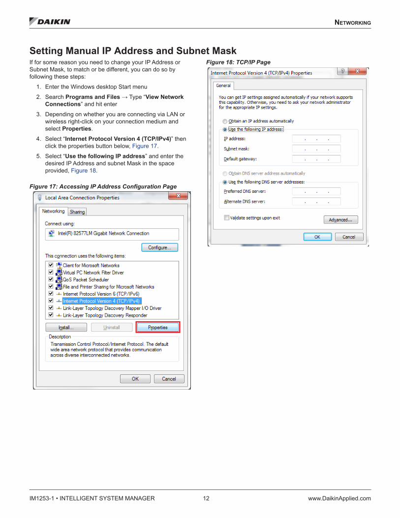
Setting Manual IP Address and Subnet MaskIf for some reason you need to change your IP Address or Subnet Mask, to match or be different, you can do so by following these steps:
1. Enter the Windows desktop Start menu
2. Search Programs and Files → Type “View Network Connections” and hit enter
3. Depending on whether you are connecting via LAN or wireless right-click on your connection medium and select Properties.
4. Select “Internet Protocol Version 4 (TCP/IPv4)” then click the properties button below, Figure 17.
5. Select “Use the following IP address” and enter the desired IP Address and subnet Mask in the space provided, Figure 18.
Figure 17: Accessing IP Address Configuration Page
Figure 18: TCP/IP Page

sTarTup
www.DaikinApplied.com 13 IM1253-1 • INTELLIGENT SYSTEM MANAGER
sTarTup
Commissioner level access will be needed during start-up for some of the actions required. Select the “login” button in the upper right corner of the screen and enter the appropriate user name and password. The default user names, passwords, and settings are shown in Table 1.
Table 1: Access Levels, User Names, Passwords for Default Users and Settings
Access Level User Name Password Settings Menu Access (Tabs/Buttons)
Guest (Default User) N/A N/A
Manage Users (View Only), System Configuration (View Only), Manage Documents
Tenant Tenant daikin123 See Guest
Maintenance Maintenance daikin123
Manage Users (may add), System Configuration, Network Setup, Manage Documents
Owner Owner daikin123Maintenance level plus access to Service and System Log tabs
Commissioning Commission daikin72639Owner level plus access to Ancillary Control, Device Templates
Discovery ModeAfter installation the Discovery Mode is the first stage for the System Manager. During this time all the devices and their associated points will be discovered if wired, powered, and addressed properly. At the top of the screen in the Daikin banner “Discovery Mode” will be displayed. Allow 10-15 minutes for the System Manager to go through this process.
If you expected to see a device and it is not appearing, there are two main things to check. Wiring tends to be the most common issue. Check the BACnet MS/TP connections of a particular device, and double check it is daisy chained appropriately if applicable. Also check to make sure the wiring is not wrapped around any source of power as this may introduce noise into the signal and prevent proper communication with the device. If wiring is fine, also check that the MAC address of the device is in the 0 to 127 range and the Device Instance number is in the 3101000 to 3101999 range. Many types of Daikin equipment will already have this addressing completed, and the Device Instance number will have its last three digits match the MAC address (e.g. 3101047 and 47).
Service Utilities – Global ActionsUse the Service tab for Global Actions, Balancing, and Network Actions.
The System Stop button will set all VAVs to unoccupied and the AHUs and WSHPs to “App Mode: OFF”. Selecting Start will set the VAVs back to occupied and AHUs and WSHPs to “App Mode: Auto”.
The tabular list shows all devices connected to the System Manager. In this list you may update a particular device’s set points, parents, or even schedules. This list makes it easy to change a large number of devices all at once rather than one at a time. If more control over a single device is desired, select the pencil icon at the end of a particular device on the list, and you may edit all three properties (set points, parents, and schedule) of a single device.
Service Utilities - BalancingEnable the Manual Mode - this will override critical control points. Once enabled, the page allows the user to select either a single air handler unit, or all known air handlers, and then select an action to perform.
• Max Flow: The air handling unit’s associated VAVs’ control flow setpoint will be overridden to 100% to maintain maximum design cfm.
• Min Flow: The air handling unit’s associated VAVs’ control flow setpoint will be overridden to the minimum percentage (Flow Minimum/Flow Maximum) to maintain the minimum design cfm.
• Open Dampers: The air handling unit’s associated VAV’s damper command setpoint will be overridden to 100%.
After selecting an action to perform press Go to command all the VAVs connected to the indicated air handler. This override will remain as long as the System Manager remains in Manual Mode. To stop the override, select Automatic. This will return VAVs back to local control.
Depending on the physical location and construction of the VAV box the Flow Coefficient may need adjusting. Scrolling down on the Balancing Tab, a Flow Coefficients table lists all of the VAV terminals recognized by the System Manager along with their Current Flow Coefficient and Displayed Air Volume. To edit a particular VAV’s flow coefficient, select the pencil icon under Action. Upon selection, you will have the ability to enter the Actual Air Volume for the VAV, and based on that the New Flow Coefficient will be calculated. This Flow Coefficient is limited in value between 0 and 2.55. Before exiting this page, remember to select Update to save any changes that have been made.

IM1253-1 • INTELLIGENT SYSTEM MANAGER 14 www.DaikinApplied.com
sTarTup
Service Utilities – Network ActionsTo remove an override on a VAV point, select the Network Actions tab. In the VAV Point Release submenu, first select one or many VAV terminals, then select one or many points to release on those VAV terminals. Once selections have been made, press the Release button to release selected points on selected VAV terminals. This Release function is also useful if any overrides were done through WCIS (described in the next section) at the VAV actuator and will release all of the overrides.
ATS Auto AssignmentATS Auto Assignment is a tool that will assist in locating and identifying the various WSHP and Fan Coil units within the building. WSHP and Fan Coil units will initiate communication on the network when the tenant override button on their associated space sensor is held in for more than 10 seconds.
The strategy for doing this is as follows. Turn on Discovery Mode in the Network Actions – ATS Auto Assignment if it is not already enabled. Go zone to zone and initiate communications on each of the WSHP and Fan Coil units right away, one right after another. Record the time and order when pressing the tenant override button for each device. Do this on all units and then go back and identify them on the Intelligent Systems by the time stamp the communication was initiated in the System Log (Owner access level and above). This will help with device labeling in the System Manager. Once devices have been discovered to your liking, press Optimize Communication. This will reassign MAC addresses to the devices that have been discovered to get them in line with the rest of the devices. This should speed up token passing on the BACnet MS/TP network.
WCIS Software Tool for VAVs CAUTION
Adjusting the application software, addressing, or setpoints on the controller can be harmful – affecting system operation and communication. Software should only be used by trained technicians experienced with the particular equipment.
WCIS is a BACnet VAV controller software that allows for gathering or manipulating setpoints and information directly on the BACnet VAV controllers through a personal computer. This can be particularly useful during balancing or in the troubleshooting of a particular VAV terminal unit because it is an unfiltered steady stream of data directly from the VAV controller itself. Also, it eliminates the typical communication delays that are present when reading data over the network. The WCIS Software Tool is used in conjunction with the WCIS cable (part number 250804701). Personal computers without a male serial connection need a serial to USB adapter. The WCIS program can be obtained by contacting the Daikin Applied controls group. Run the setup.exe file and follow the wizard instructions.
The WCIS cable RJ-11 connector can be plugged into the bottom of the room sensor connected to the VAV actuator, or directly into the VAV actuator room sensor input. Open the WCIS Software Tool on your PC. Select Device and then Connection Settings to configure the software, see Figure 19. Select the appropriate COM port on your PC that has the WCIS cable connected, and use the default Baud Rate (1200). Use Device Address of 99 and select OK. Select Device and then Connect, a pop-up screen will appear, press OK. The software should have a highlighted row scrolling through continuously updating the data points.
Figure 19: Connection Settings in WCIS

sTarTup
www.DaikinApplied.com 15 IM1253-1 • INTELLIGENT SYSTEM MANAGER
Applications and setpoints can be viewed and manipulated in the software. To change point values double-click on the value to open a new screen. The pop-up screen will give a brief description of the data point, and the value can be adjusted in the text box, after adjustments select OK to save configurations. Some convenient data points to view and configure are: controller address, cooling and heating setpoints, flow minimums and maximums, air volume, flow coefficient, and duct area. For more information on data points, refer to OM 1063 BACnet VAV Actuator Operation Manual.
NOTE: Anytime you make a manual change to a data point in WCIS, you are overriding that point and disabling the internal logic that generally governs it. This will be indicated to you in the WCIS tool, under the stats column. You must release that point again before the controller will return to normal operation! Right click on the column to release the point in WCIS, or this can be done globally at the System Manager under the service tab. Also, if a point has failed because of an input that doesn’t exist or a hardware issue, it will show up as a red line and this will be indicated in the status column as well.

IM1253-1 • INTELLIGENT SYSTEM MANAGER 16 www.DaikinApplied.com
sChedulIng
sChedulIng
Scheduling is done at a zone level, not at an air handling unit level. The VAV boxes, WSHPs, and Fan Coil Units are assigned to schedules, and their parent devices will follow their schedules.
Creating SchedulesTo create a schedule, select the “Schedule” tab. A window labeled “Manage Schedules” will appear with a list of existing schedules. To create a new schedule, select the “Add New Schedule” button. A weekly schedule will appear with a default setting of occupied times on Monday through Friday and unoccupied on the weekend. Occupied is represented in blue and Unoccupied is represented in white.
Give the schedule a unique name at the top of the window. If the name matches another schedule, a notification at the top saying “A schedule by this name already exists.” will appear. Set up the desired schedule by sliding the slider tabs to adjust times, or by pressing the clock button to the right of the times to enter the desired time, shown in Figure 20. For each day a maximum of 4 slider bars is allowed. To add a slider bar, select “+”. To remove the last slider bar added, select “X”. To switch the occupied and unoccupied times in a day select “Toggle Occupancy”.
Holiday schedules can be added by selecting the “Holiday Schedule” subtab. Here the user can add holidays assigned for special hours of operation on a specific day.
Giving Devices a ScheduleWith a new schedule being created, the user must specify which devices are going to follow the new schedule. Select the “Devices” subtab. A dropdown box appears listing all of the connected devices, shown in Figure 21. To select a device, select it from the dropdown box and a checkmark will appear to the left of the device name. In addition, the device’s name will now appear below the “Assign Devices to Schedule” menu. To remove a device from the schedule, select the “X” next to the device name below “Assign Devices to Schedule” or go into the dropdown box and select the device name again to remove the checkmark. When finished, click “Save” and Intelligent Systems will display a notification confirming the action.
Figure 20: Adjusting Schedule Times
Figure 21: Assign Devices to Schedule

sChedulIng
www.DaikinApplied.com 17 IM1253-1 • INTELLIGENT SYSTEM MANAGER
To quickly reference what devices are following which schedule, select the “Schedules” tab. On the list of saved schedules, a black arrow will be next to any schedule with assigned devices. Toggle the arrow to see what devices are currently assigned to the schedule, along with a room temperature measurement for each device, shown in Figure 22. The device listings are also linked back to their respective device information and settings page.
Adding Users1. Login as Maintenance access level or higher
2. Select the “Settings” tab
3. Select “Manage Users” (Figure 23)
4. Select the “New User” button
5. Input the required information into the “Add User” window: First Name, Last Name, User Name, Security Level*, Password that meets listed criteria, and confirmed Password. (Figure 24)
6. Once all information has been entered, select “Add”
NOTE: *The access level at which you login will dictate the level of access you may provide to the new user. Table 2 lists the access levels from lowest to highest. For instance, since a commissioner is the highest access level, they can create a new user with any access. An owner, though, cannot create a commissioner level, but can create a user with any other access level.
Table 2: Access Levels, User Names, Passwords for Default Users and Settings
Access Level User Name Password Settings Menu Access (Tabs/Buttons)
Guest (Default User) N/A N/A
Manage Users (View Only), System Configuration (View Only), Manage Documents
Tenant Tenant daikin123 See Guest
Maintenance Maintenance daikin123Manage Users (may add), System Configuration, Network Setup, Manage Documents
Owner Owner daikin123Maintenance level plus access to Service and System Log tabs
Commissioning Commission daikin72639Owner level plus access to Ancillary Control, Device Templates
NOTE: For security purposes, it is recommended to change the default passwords from what is published in OM 1254. Be sure to record them somewhere for safe keeping. Passwords cannot be reset again without higher level access.
Figure 22: Schedule Device Quick Reference

IM1253-1 • INTELLIGENT SYSTEM MANAGER 18 www.DaikinApplied.com
sChedulIng
Figure 23: Manage Users Page
Figure 24: Add User Page

sChedulIng
www.DaikinApplied.com 19 IM1253-1 • INTELLIGENT SYSTEM MANAGER
Saving the ConfigurationAfter completing the setup for the System manager, save the configuration file. This will have all the settings created and allows for quick recovery in the event of a PC failure. To do so follow these steps (refer to Figure 25):
1. Go to the “Settings” tab → “System Configuration”
2. Under “System Actions” press the “Export Local Config” button
The configuration is now saved in case of future need to upload the file to return to the systems original settings. It is recommended to save the configuration file to a USB flash drive. The location of the LocalConfig.xml file is C:\MISystem\Config\System.
In addition to saving the LocalConfig.xml file, it is also recommended to save and send Template xml files. They organize device information on each Device Property page and are located in C:\MISystem\Config\Templates – please create a .zip file of the Config folder (outlined in the next paragraph). If some devices do not have templates in place you may either read up on how to create and edit your own templates in “Manage Device Templates” under “Settings,” or contact Daikin Applied.
Figure 25: Saving the Configuration
To save the current configuration and template files to a removable storage device, simply plug the device into the USB port located on back of the Intelligent Systems. You must first minimize the browser window by touching (or clicking if a mouse is connected) at the upper right hand corner of the screen. With the browser minimized, navigate to the appropriate folder by double clicking the “My Computer” icon, and then navigating to C:\MISystem\. Locate the Config file, then press and hold (or right click if using a mouse). In the menu that appears, select “Send to…” and in the side menu select “Compressed (zipped) folder” (refer to Figure 26). This will create a new .zip folder of the Config folder in the same area. The file will automatically be looking for a new name, but renaming is optional. Tap in the empty space of the file explorer to exit out of changing the file name – or enter a new name. Once renaming is complete (changed or not), press and hold on the zipped Config file. In the menu that appears, select copy. Then on the left side of the file explorer, look for the flash drive connected under Computer. If it does not appear, double tap or double-click on Computer to see the various storage locations available and find and select your USB drive. Once in your USB drive, press and hold anywhere in the file area for the USB until the menu appears, and select Paste.
It is recommended to email the Config.zip file to [email protected]. This will ensure any replacement PCs get set up prior to shipping.
Figure 26: Creating a Zipped File

IM1253-1 • INTELLIGENT SYSTEM MANAGER 20 www.DaikinApplied.com
sChedulIng
System Manager Back Plate ConnectionsSee the System Manager back plate in Figure 27.
Figure 27: System Manager Back Plate
LED IndicatorsFour LED indicators provide diagnostic information.
• LED D1 – Flashes each time the Communication Module sends a message to the host PC
• LED D2 – Flashes each time the Communication Module receives a message from the host PC
• LED D3 – Flashes each time the Communication Module sends a message to the MS/TP network
• LED D4 – Flashes each time the Communication Module receives a message from the MS/TP network
MS/TP Network ConnectorA four pin plug connector is used to connect to the MS/TP network. For troubleshooting purposes, the start-up LED sequence may be useful:
On power-up:1. All LEDs ON.
2. LED D1 OFF immediately after power, then short pulse about every 4 seconds. This is a request to the Intelligent Systems computer to send configuration data to the BACnet module. The other three LEDs remain ON until the BACnet module is configured by the Intelligent Systems application.
When the Intelligent Systems Application starts:
1. LED D2 short pulse indicating Intelligent Systems application is sending configuration data to the BACnet module.
2. LED D3 starts fast flicker as the BACnet module is now sending Poll for Master (PFM) requests to the BACnet network.
3. LED D4 remains ON steady indicating no network traffic received.
4. LED D2 flickers about every 8 seconds as Intelligent Systems sends Who-IS requests attempting to wake up devices that may connect to the MS/TP network.
LAN 1/LAN 2 & USBRJ-45 or Ethernet connections used to connect the System Manager to the Internet. The other port may be used for troubleshooting or other applications.
The USB ports are there for uses such as: Keyboard, Mouse, external storage, etc.
VGA & HDMIThe System Manager by default is connected through VGA to the touch screen. If desired, it could be instead hooked up through HDMI to a different display.
Power Connection (PWR)This pin connection is used to deliver power to the System Manager. The actual power button is found on the front plate on the left side.
Headphone & Microphone JackAlthough there is no sound currently being emitted by the System Manager, these ports are also included on the back of the device (it is a computer with internet access, so it could potentially need sound).

TroubleshooTIng
www.DaikinApplied.com 21 IM1253-1 • INTELLIGENT SYSTEM MANAGER
TroubleshooTIng
Error/Condition Problem Solution
System Manager doesn’t find all devices on the network
• Check network wiring for loose or nicked wires. Ensure polarity for each conductor is maintained throughout all devices
• Verify the devices have power applied• Verify the Device Instance and MS/TP address on the unit controllers• Check the Min and Max Device Instance on the Settings/Network Setup
screen• Check the network addressing and baud rate• Verify the network twisted-pair shield should only be earth grounded at
one location• Verify the EOL resistors are installed properly• Install bias resistors• Verify network wiring is apart from AC power, VFDs, or other devices
causing network interference
MicroTech III RTU controller isn’t communicating to the System Manager
• See steps above in “System Manager doesn’t find all devices on the network”
• Verify the BUS LED and BSP LED are green signifying communication capability
VAV actuator isn’t communicating to the System Manager
• See steps above in “System Manager doesn’t find all devices on the network”
• Verify the RX LED and TX LED are flashing signifying communication
Can’t communicate to the System Manager through a direct connection on my laptop
• Compare the IP Address of your computer to the IP Address of the System Manager.
• Verify you are on the same subnet.• Turn firewall off on System Manager
Can’t log in to my System Manager Incorrect username or password• The password is case sensitive. Be sure you are typing the username
and password correctly.• Use a higher access level to reset your password
Alarms are not being sent to my phone or email
Which alarms are sent depend on the configuration in the System Manager and the configuration of the unit controller
• While logged in to the System Manager go to Settings, then System Configuration. Select Alarm Configuration, and scroll all the way down.
• Verify the “Enable Email/Text Alarming” checkbox is checked and select “Save”
Cannot access certain screens or data on my System Manager
You are most likely logged on at a lower user level than is needed for that particular screen • Log in under higher user access level to access additional menus
I try to access certain screens like the list or property pages, but I’m redirected to the main screen
The server is disabled. The main screen shows the message “VAV Server Disabled”
• Start the server with the link on the System Manger desktop• Reboot System Manager PC with toggle switch
The points I want to trend on the Trend Log page are not available in the object drop down list
This object is either not available for this unit, has not yet been read or is not setup to be trended
• Verify the point you are looking for is a valid point for this unit.• Verify the data point is configured for trending by accessing the “Unit
Config” menu. See OM 1254 for details.
I try to add a user, but the User Level I want to assign is not available
You can only add users with a User Level equal to or lower than the User Level you are currently logged in as
• Assign the new user a different user level. • Log in as a higher level user and create the new user.• Have some with a higher user level add the new user.
System Manager is responding slowly, showing timeout errors, or not applying changes I’ve made
• System Manager is overburdened• Communication errors are consuming PC
resources
• Verify communications are clean by accessing the event log on the System Manager (see OM 1254 for details)
• Reduce trended points, trend intervals, or trend history. Also reduce Event Log history.
The application works fine when I access it locally or from within a local network, but seems incomplete or broken when accessed from outside
• Your local IT firewall may be causing an issue• Too many users are accessing the System
Manager simultaneously
• Consult with local IT staff on troubleshooting firewall rules. This may be commonly caused by an Internet-facing firewall rule that denies an ampersand ‘&’ within URL headers, though there may be other issues.
• Close your web browser and try back later.

IM1253-1 • INTELLIGENT SYSTEM MANAGER 22 www.DaikinApplied.com
TroubleshooTIng
Event Log TroubleshootingNetwork health is key to proper operation and control over any system. Verifying that the communications are happening properly can ensure prompt responsiveness during your interaction with the System Manager and eliminate potential issues down the road. A healthy Intelligent Systems network is one where the System Manager requests updates and writes data to the various unit controllers and they respond appropriately without errors or timeout events. Unhealthy communication events will show up in the Event Log and may indicate a wiring, addressing, or hardware problem. For this reason, it is recommended that you view the Event Log to determine if any of these events are occurring at the time of startup so they can be addressed immediately.
To access the Event Log, log in to the System Manager at a owner level access or higher. From the Home screen, select Event Log. Here you will be able to view the raw BACnet communications between the System Manager and all the HVAC devices on the network. The table below indicates several events that might indicate a “dirty” network and suggested troubleshooting for each type.
Error/Condition Problem Solution
UART errors Physical wiring issue, or duplicate addresses on the network
• Check the network wiring• Check the Device Instance and MS/TP Address on the unit controllers
– Compare to correct addresses in Settings → Network Setup → System Summary
Timeouts No communication to devices. Timeouts could be for a particular device, or for many devices.
• See steps in Troubleshooting “System Manager doesn’t find all devices on the network
Pet MTM The MTM is trying to get a response from the network due to communication errors. • Check LEDs and view LED Indicators on page 39.
MTM_TryConfig
Indicates the MTM is not responding. Normally this would be accompanied with an MTM Failure alarm if a cable had fallen off or the MTM completely failed. Since the MTM would respond before the alarm occurred, the alarm was not created.
• MTM board may be defective

TroubleshooTIng
www.DaikinApplied.com 23 IM1253-1 • INTELLIGENT SYSTEM MANAGER
TroubleshooTIng
Figure 28: Intelligent Systems Alarms Troubleshooting Decision Tree Alarms Troubleshooting Decision Tree
BACnet Module Failure Communication Failure
Check API and BACnetfirmware main version
numbers on Settings pageto see if they are similar
Upgrade needed for BACnet Communication
board or Intelligent Systems application
No?
Are all units uniquelyaddressed? Readdress unitsNo?
Is wiring doneproperly?
All wires securelyconnected?
Polarity maintained? Earth ground at one
location? No splices?
Redo wiringNo?
Check LEDs on BACnetCommunication board, are
they flashing?No?
Alarms Cause Troubleshoot Solution
Loss of communication to aunit
Unit wiring, addressing, orpower failure
Are all units uniquelyaddressed? Readdress unitsNo?
Is wiring doneproperly?
All wires securelyconnected?
Polarity maintained? Earth ground at one
location? No splices?
Redo wiringNo?
Is the unit Device Instancein the System ManagerNetwork Setup Device
Instance range?No?
Are the terminationresistors installed properly?
Install 120Ω terminationresistorsNo?
Are communications clearof AC power, VFDs andother devices causingnetwork interference?
No?
On the Settings/Generalcheck the Initialize Network
on Startup, press Save.Then go to the Home page
and press Restart.
Verify or changeDevice Instance rangeon Settings/NetworkSetup page
Readdress units

IM1253-1 • INTELLIGENT SYSTEM MANAGER 24 www.DaikinApplied.com
TroubleshooTIng
Figure 29: Intelligent Systems System Log Troubleshooting Decision Tree
Timeouts
MTM_TryConfig
Object reference not set toan instance of an object
Pet MTM
BACnet CommunicationBoard not responding
System Log Troubleshooting Decision Tree
Are the BACnetCommunication cables
secured and wiredproperly?
RS232 cable connectedproperly?
Redo wiringNo?
No?
Check LEDs on back ofSystem Manager, are they
flashing?
On the Settings/Generalcheck the Initialize Network
on Startup, press Save.Then go to the Home page
and press Restart.
No?
Communication Failure Are all units uniquelyaddressed? Readdress unitsNo?
Is wiring doneproperly?
All wires securelyconnected?
Polarity maintained? Earth ground at one
location? No splices?
Redo wiringNo?
Check LEDs on back ofSystem Manager, are they
flashing?No?
UART Error
MTM Negotiating Data Upgrade needed for BACnet Communication
board or Intelligent Systems application
No?
Ser.Rx MTM UndefinedSimple Request Data Error
BACnet Communicationboard possibly needs to be
updated or has failed
Go through communicationfailure troubleshooting
steps
Issue Cause Troubleshoot Solution
On the Settings/Generalcheck the Initialize Network
on Startup, press Save.Then go to the Home page
and press Restart.
Check API and BACnetfirmware main version
numbers on Settings pageto see if they are similar
TroubleshooTIng
www.DaikinApplied.com 25 IM1253-1 • INTELLIGENT SYSTEM MANAGER
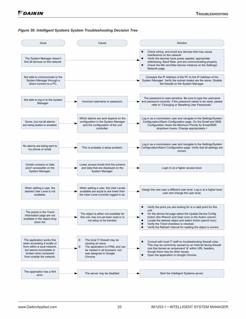
Figure 30: Intelligent Systems System Troubleshooting Decision Tree System Troubleshooting Decision TreeIssue Cause Solution
The System Manager doesn’t find all devices on the network.
Check wiring, and avoid any devices that may causeinterference on the network.
Verify the devices have power applied, appropriateaddressing, Baud Rate, and are communicating properly.
Check the Min and Max Device Instance on the Settings/Network page.
Not able to communicate to theSystem Manager through a
direct connect to a PC.
Compare the IP Address of the PC to the IP Address of theSystem Manager. Verify the subnet masks are the same. Disable
the firewall on the System Manager.
Not able to log in to the SystemManager. Incorrect username or password.
The password is case sensitive. Be sure to type the usernameand password correctly. If the password needs to be reset, please
refer to “Changing or Resetting User Passwords”.
Some, but not all alarmsare being texted or emailed.
Which alarms are sent depend on theconfiguration in the System Manager
and the configuration of the unitcontroller.
Log in as a commission user and navigate to the Settings/SystemConfiguration/Alarm Configuration page. On the Email and SMS
Configuration check the Minimum Priority for Email/SMSdropdown boxes. Change appropriately.=
Certain screens or dataaren’t accessible on the
System Manager.
Lower access levels limit the screensand data that are displayed on the
System Manager.Login in at a higher access level.
When adding a user, thedesired User Level is not
available.
When adding a user, the User Levelsavailable are equal to are lower thanthe User Level currently logged in as.
Assign the new user a different user level. Log in at a higher leveluser and change the user level.
No alarms are being sent tomy phone or email. This is probably a setup problem.
Log in as a commission user and navigate to the Settings/SystemConfiguration/Alarm Configuration page. Verify that all settings are
correct.
The points in the TrendInformation page are not
available in the object dropdown list.
The object is either not available forthis unit, has not yet been read or is
not setup to be trended.
Verify the point you are looking for is a valid point for thisunit.
On the device list page select the Update Device Configbutton (the Wrench and Gear icon) in the Action column.
Locate the desired object and select Action (pencil icon). Verify the Trend checkbox is checked. Verify the Refresh Interval for reading the object is correct.
The application works finewhen accessing it locally orfrom within a local network,
but seems incomplete orbroken when accessed
from outside the network.
� The local IT firewall may becausing an issue.
� The application is HTML and canbe viewed in all browsers, butwas designed in GoogleChrome.
Consult with local IT staff on troubleshooting firewall rules.This may be commonly caused by an Internet facing firewallrule that denies an ampersand ‘&’ within URL headers,though there may be other issues.
Open the application in Google Chrome.
The application has a 404error. The server may be disabled. Start the Intelligent Systems server.

IM1253-1 • INTELLIGENT SYSTEM MANAGER 26 www.DaikinApplied.com
TroubleshooTIng
Figure 31: VAV Troubleshooting Decision Tree VAV Troubleshooting Decision Tree
Air volume reading of 0 cfm Is there air passingthrough?
Are intake tubes connectedproperly and in the right
positions?
Is the damper closed?Reverse direction of damper by manually rotating the damper, or through the Intelligent Systems
Electric heat won’t enable Is there sufficient airflowgoing through the box?
Minimum 70 cfm per kW toenable heating
Check setpoints
Check heating and coolingloopouts
Check mode
Check switch deadband
Default is 10 minutes, if theappropriate conditions are met forthe length of time set in the switch
time the VAV will switch fromcooling to heating
Yes
Is the airflow sensorinstalled properly?Yes
Issue Cause Troubleshoot Solution
Ensure there isn’t air leakage coming from the tubing. The bluestripe tubing is the HIGH pressureside and is what the air hits first.
The red striped tubing is the LOWpressure side and is the farthest
away from the airflow.
No
Install the airflow sensor properly.No
No Yes
No Air flow must be increased tosatisfy mechanical safety switches.No
Adjust setpoints if necessary
The loopouts show the demand forheating/cooling. The heating
loopout must be above zero toenable heating.
Ensure the VAV is in heat mode
The switch deadband default is 1°F, the control temp must be less than the control setpoint by at least the value
of the switch deadband to go into heating
Check switch time
Check application number
2562 = Single duct withelectric reheat/baseboardradiation
2563 = Single duct with SCRelectric reheat
2564 = Series fan with electricreheat
2565 = Series fan with SCRelectric reheat
2566 = Parallel fan withelectric reheat
2567 = Parallel fan with SCRelectric reheat

warranTy regIsTraTIon form
www.DaikinApplied.com 27 IM1253-1 • INTELLIGENT SYSTEM MANAGER
warranTy regIsTraTIon form
13F-4181 (02/17) ©2017 Daikin Applied • (800) 432-1342 • www.DaikinApplied.com
System Manager Equipment Warranty Registration FormTo comply with the terms of Daikin Applied Warranty, complete and return this form within 10 days to Daikin Applied at [email protected].
Check, test, and start procedure for Intelligent Systems™.
GENERAL INFORMATION
Job Name: ____________________________________________________________ SOI No.:________________________________
Installation address: _____________________________________________________________________________________________
City: _________________________________________________________________ State: _________________________________
Purchasing contractor: ___________________________________________________________________________________________
City: _________________________________________________________________ State: _________________________________
UNIT INFORMATION
Model Number: ________________________________________________________ Serial Number: __________________________
BRING TO SITE (OPTIONAL)
□ OM 1254
□ IM 1253
□ Laptop
□ USB storage device
□ USB Keyboard
□ USB mouse
□WCIS Cable (p/n 250804701)
□ Control Screwdriver

IM1253-1 • INTELLIGENT SYSTEM MANAGER 28 www.DaikinApplied.com
warranTy regIsTraTIon form
System Manager Equipment Warranty Registration Form (continued)
13F-4181 (02/17) 2
Select Yes, No or Complete.
I. Initial CheckA. Is there any shipping damage to System Manager?. . . . . . . . . . . . . . . . . . . . . . . . . . . . . Yes □ No □B. Is the System Manager installed and powered with 120VAC?. . . . . . . . . . . . . . . . . . . . . . . . Yes □ No □C. Is each Rooftop or Self Contained unit installed and started up per their Installation Manual? . . . . . . . Yes □ No □D. Is duct and building pressure tubing run to pressure transducers per unit Installation Manual? . . . . . . Yes □ No □
Unit ManualRPS/RDT/RFS/RCS 015C-105C IM 926RPS/RDT/RFS/RCS 050D-140D IM 893SWP Self-Contained 018-105 IM 937RoofPak® RAH/RDS IM 987Maverick® II Rooftop 62-75 ton IM 991Maverick® II Rooftop 15-50 ton IM 1058Rebel® IM 1125
E. Is each WSHP unit installed and started up per their Installation Manual? . . . . . . . . . . . . . . . . . Yes □ No □Unit ManualSmartSource® GSH/GSV IM 1139SmartSource® GTH/GTV IM 1140Enfinity® CCH/CCW ½-6 ton IM 1049Enfinity® CCH/CCW 6-10 ton IM 1060Enfinity® LVC/LVW IM 1059Enfinity® VFC/VFW IM 930Vertical Stack VHC/VHF IM 986
F. Is each Fan Coil Unit with MicroTech III controls installed and started up per their Installation Manual? . . Yes □ No □Unit ManualThinLine Horizontal Fan Coils IM 1152
G. Is the LWM unit installed and started per IOM 1150? . . . . . . . . . . . . . . . . . . . . . . . . . . . . Yes □ No □H. Is the I/O Manager installed and started per IOM 1135?. . . . . . . . . . . . . . . . . . . . . . . . . . . Yes □ No □I. Is each VAV unit located as indicated on the building plans? . . . . . . . . . . . . . . . . . . . . . . . . Yes □ No □J. Is each VAV unit installed per IM 1063? . . . . . . . . . . . . . . . . . . . . . . . . . . . . . . . . . . . Yes □ No □K. Are the communication wires to each VAV box, air handler, and System Manager installed
per the BACnet MS/TP wiring specification? . . . . . . . . . . . . . . . . . . . . . . . . . . . . . . . . Yes □ No □1. 22 AWG, shielded twisted pair? . . . . . . . . . . . . . . . . . . . . . . . . . . . . . . . . . . . . Yes □ No □2. 120 ohm terminal resistors on each end? . . . . . . . . . . . . . . . . . . . . . . . . . . . . . . . Yes □ No □3. Polarity (+/-) verified at each device? . . . . . . . . . . . . . . . . . . . . . . . . . . . . . . . . . Yes □ No □4. Shield grounded at one location only: Location of shield ground:_________________ . . . . . . . Yes □ No □
L. Are all space sensors wired to VAV controllers with cat3 cable provided? . . . . . . . . . . . . . . . . . Yes □ No □M. Optional: Is the System Manager PC installed on a network for remote access?* . . . . . . . . . . . . . Yes □ No □
1. Panel static IP address:____________________________ . . . . . . . . . . . . . . . . . . . . . . Yes □ No □N. Is the electrical wiring completed and power applied to all devices and System Manager?. . . . . . . . . Yes □ No □O. Is control wiring run from VAV Box controller to appropriate field controls per wiring diagrams provided? . Yes □ No □

warranTy regIsTraTIon form
www.DaikinApplied.com 29 IM1253-1 • INTELLIGENT SYSTEM MANAGER
System Manager Equipment Warranty Registration Form (continued)
13F-4181 (02/17) 3
Select Yes, No or Complete.
*NOTE: It is the building owner’s responsibility to properly protect the System Manager PC that is connected to the internet with the appro-priate protection software as required (firewall, anti-virus, anti-spyware, etc).
Exceptions to the initial check:
____________________________________________________________________________________________________
____________________________________________________________________________________________________
____________________________________________________________________________________________________
____________________________________________________________________________________________________
II. Start-upA. Do you have IM 1253 and OM 1254 for System Manager? . . . . . . . . . . . . . . . . . . . . . . . . . Yes □ No □B. Apply power to the System Manager and allow the system to boot up . . . . . . . . . . . . . . . . . . . Complete □C. Perform calibrate procedure per IM or OM. . . . . . . . . . . . . . . . . . . . . . . . . . . . . . . . . . Complete □D. Set time/date on system panel per IM or OM . . . . . . . . . . . . . . . . . . . . . . . . . . . . . . . . Complete □E. Reboot System Manager via the “Restart” button on the home screen . . . . . . . . . . . . . . . . . . . Complete □F. Launch Google Chrome browser if it did not start automatically . . . . . . . . . . . . . . . . . . . . . . . Complete □G. Allow several minutes (up to 30) for the panel to discover all units connected to the MS/TP trunk.
During this time “Discovery Mode Active” will appear at the top of the screen. . . . . . . . . . . . . . . . Complete □H. Were all devices discovered successfully? . . . . . . . . . . . . . . . . . . . . . . . . . . . . . . . . . Yes □ No □I. Note all units not discovered in the exceptions portion following . . . . . . . . . . . . . . . . . . . . . . Complete □J. Resolve any discrepancies in communication by verifying power and communication wiring to devices . . Complete □
Exceptions to the startup:
____________________________________________________________________________________________________
____________________________________________________________________________________________________
____________________________________________________________________________________________________
____________________________________________________________________________________________________

IM1253-1 • INTELLIGENT SYSTEM MANAGER 30 www.DaikinApplied.com
warranTy regIsTraTIon form
System Manager Equipment Warranty Registration Form (continued)
13F-4181 (02/17) 4
Select Yes, No or Complete.
III. System ConfigurationOnce all units are running and there are no communications errors, ATS Auto Commissioning should be run to confirm all units are underthe control of the System Manager and to resolve any discrepancies between the factory configuration and actual build. Run the ATSAuto Commissioning by following the instructions in the System Manager Operators Manual (OM 1254) or System Manager InstallationManual (IM 1253).
A. Run ATS Auto Commissioning for WSHP and Fan Coil Units.. . . . . . . . . . . . . . . . . . . . . . . . Yes □ No □B. Were the WSHP and FCU units found successfully? . . . . . . . . . . . . . . . . . . . . . . . . . . . . Yes □ No □C. Were the WSHP and FCU units assigned successfully? . . . . . . . . . . . . . . . . . . . . . . . . . . Yes □ No □D. Save the Current System. . . . . . . . . . . . . . . . . . . . . . . . . . . . . . . . . . . . . . . . . . . Complete □E. Export the new system configuration and save to a remote storage device . . . . . . . . . . . . . . . . . Complete □
1. Location of local configuration xml file:______________________________
F. Email the local configuration file to [email protected] . . . . . . . . . . . . . . . . . . . . . Complete □
Notes from System Configuration:
____________________________________________________________________________________________________
____________________________________________________________________________________________________
____________________________________________________________________________________________________
____________________________________________________________________________________________________
Thank you for completing this form. Please sign and date below.
Performed By: ________________________________________ Title: ______________________________________
Signature _____________________________________________________________ Startup date: ___________________________
Return completed form by mail to: Daikin Warranty Department, 13600 Industrial Park Boulevard, Minneapolis, MN 55441
or by email to: [email protected] Please fill out the Daikin Applied “Quality Assurance Survey Report” and list any additional comments that could affect the operation of this unit; e.g., shipping damage, failed components, adverse installation applications, etc. If additional comment space is needed, write the comment(s) on a separate sheet, attach it to the Survey Report and return it to the Warranty Department of Daikin Applied with the completed Equipment Warranty Registration form.

QualITy assuranCe survey form
www.DaikinApplied.com 31 IM1253-1 • INTELLIGENT SYSTEM MANAGER
QualITy assuranCe survey form
Quality Assurance Survey Report
To whom it may concern:Please review the items below upon receiving and installing our product. Select N/A on any item that does not apply to the product.
Job Name: _____________________________________________________________________ Daikin Applied S.O. No. _______________
Installation address: ____________________________________________________________________________________________________
City: ___________________________________________________________________________ State: _______________________________
Purchasing contractor: __________________________________________________________________________________________________
City: ___________________________________________________________________________ State: _______________________________
Name of person doing start-up (print): ___________________________________________________________________________________
Company name: ______________________________________________________________________________________
Address: ____________________________________________________________________________________________
City/State/Zip: _______________________________________________________________________________________
Unit model number: ____________________________________________________ Unit serial number: __________________________
1. Is there any shipping damage visible? . . . . . . . . . . . . . . . . . . . . . . . . . . . . . . . . . . . . . . . . . . . . . . . . . . . . . . . . . . . . . . . . . . Yes No N/A
Location on unit ____________________________________________________________________________________
2. How would you rate the overall appearance of the product; i.e., paint, fin damage, etc.?Excellent Good Fair Poor
3. Did all sections of the unit fit together properly? . . . . . . . . . . . . . . . . . . . . . . . . . . . . . . . . . . . . . . . . . . . . . . . . . . . . . . . . . . Yes No N/A4. Did the cabinet have any air leakage? . . . . . . . . . . . . . . . . . . . . . . . . . . . . . . . . . . . . . . . . . . . . . . . . . . . . . . . . . . . . . . . . . . Yes No N/A
Location on unit ___________________________________________________________________________________
5. Were there any refrigerant leaks? . . . . . . . . . . . . . . . . . . . . . . . . . . . . . . . . . . . . . . . . . . . . . . . . . . . . . . . . . . . . . . . . . . . . . Yes No N/A
From where did it occur? . . . . . . . . . . . . . . . . . . . . . . . . . . . . . . . . . . . Shipping Workmanship Design
6. Does the refrigerant piping have excessive vibration? . . . . . . . . . . . . . . . . . . . . . . . . . . . . . . . . . . . . . . . . . . . . . . . . . . . . . . Yes No N/A
Location on unit ___________________________________________________________________________________
7. Did all of the electrical controls function at start-up? . . . . . . . . . . . . . . . . . . . . . . . . . . . . . . . . . . . . . . . . . . . . . . . . . . . . . . . Yes No N/A
Comments _______________________________________________________________________________________
8. Did the labeling and schematics provide adequate information? . . . . . . . . . . . . . . . . . . . . . . . . . . . . . . . . . . . . . . . . . . . . . . Yes No N/A
9. How would you rate the serviceability of the product?Excellent Good Fair Poor
10. How would you rate the overall quality of the product?Excellent Good Fair Poor
11. How does the quality of Daikin Applied products rank in relation to competitive products?Excellent Good Fair Poor
Comments _______________________________________________________________________________________
Please list any additional comments which could affect the operation of this unit; i.e., shipping damage, failed components, adverse installation applications, etc. If additional comment space is needed, write the comment(s) on a separate sheet, attach the sheet to this completed Quality Assurance Survey Report, and return it to the Warranty Department with the completed preceding “Equipment Warranty Registration Form”.
13F-4160 (02/16) ©2016 Daikin Applied • (800) 432-1342 • www.DaikinApplied.com

IM1253-1 (02/17) ©2017 Daikin Applied | (800) 432–1342 | www.DaikinApplied.com
Daikin Applied Training and DevelopmentNow that you have made an investment in modern, efficient Daikin equipment, its care should be a high priority. For training information on all Daikin HVAC products, please visit us at www.DaikinApplied.com and click on Training, or call 540-248-9646 and ask for the Training Department.
Warranty
All Daikin equipment is sold pursuant to its standard terms and conditions of sale, including Limited Product Warranty. Consult your local Daikin Applied representative for warranty details. To find your local Daikin Applied representative, go to www.DaikinApplied.com.
Aftermarket Services
To find your local parts office, visit www.DaikinApplied.com or call 800-37PARTS (800-377-2787). To find your local service office, visit www.DaikinApplied.com or call 800-432-1342.
This document contains the most current product information as of this printing. For the most up-to-date product information, please go to www.DaikinApplied.com.
Products manufactured in an ISO Certified Facility.