Installation manual FROG-A24 / FROG-A24E€¦ · Installation manual FROG-A24 / FROG-A24E English...
16
UNDERGROUND OPERATOR FOR SWING GATES 119AU35EN Installation manual FROG-A24 / FROG-A24E Englis h EN
-
Upload
truongkiet -
Category
Documents
-
view
264 -
download
0
Transcript of Installation manual FROG-A24 / FROG-A24E€¦ · Installation manual FROG-A24 / FROG-A24E English...

UNDERGROUND OPERATOR FOR SWING GATES119AU35EN
Installation manual
FROG-A24 / FROG-A24E
English EN
Pag
e 22
-
Man
ual
cod
e: 1
19A
U3
5EN
119
AU
35
EN
ver
. 55
0
5/2
014
©
CA
ME c
ance
lli a
uto
mat
ici S
.p.A
. -
The
dat
a an
d in
form
atio
n p
rovi
ded
in t
his
man
ual
are
subje
ct t
o ch
ange
at a
ny t
ime
with
out
prior
not
ice
by
CA
ME C
ance
lli A
uto
mat
ici S
.p.a
.
EN
GLIS
H
Introduction
• Use this product only for the specifi c purpose for which it is designed. Any other use is therefore improper and dangerous. CAME Cancelli Automatici S.p.A. is not liable for any damage due to improper, erroneous and unrea-sonable use • Keep these warnings together with the installation and users' manual for the automation system.
Before installing
(check what's there: if you fi nd something wrong, proceed only after correcting the problem so the equipment is safe to use)• Check that the part you want to automate is in good mechanical condition, that it is balanced and aligned, and that it opens and closes properly. Make sure you have suitable mechanical stops • If the operator will be installed less than 2.5 m from the fl oor or from any other access level, check whether you need additional protections and/ or warnings • With pedestrian doors framed into the doors that will be automated, a system must be in place to block their opening during movement • Make sure the opening of the automated door leaf does not cause any trapping situations involving any surrounding fi xed parts • Do not install the operator upside down or on any elements that may bend. If necessary, add suitable reinforcements at the fastening points • Do not install on sloping ground (only install on fl at ground) • Check that any watering devi-ces cannot wet the gearmotor from the bottom upwards.
Installation
• Properly signal and demarcate the entire site prevent any careless people from entering the works area • Be careful when handling operators that weigh more than 20 kg (see installation manual. If such is the case, make sure you have proper hoisting equipment. All opening commands (buttons, key selec-tors, magnetic card readers, and so on) must be installed at least 1.85 M from the gate's area of movement, or so that they are unreachable from the outside. Moreover, the direct commands (from buttons, swipe cards, and so on) must be installed 1.5 m high off the ground and must not be reachable by the public • All "hold-to-run" commands must be placed where the operating gate leaves and transit areas are completely visible. • Apply a permanent label that shows the position of the release device • Before turning over the instal-lation to the user, check that the system conforms to standards EN 12453 and EN12445 (impact testing), making sure the device has been properly adjusted and that the safety and protection and release devices function properly • Where necessary apply the Warning Signs so that they are clearly visible (e.g. the gate plate)
Instructions and special recommendations for users
• Keep the barrier's areas of operations unobstructed. Check that the photo-cells are free of any vegetation blocking them, and that there are no obstacles to the free movement of the operator. Do not allow children to play with the fi xed command devices, or in the barrier's area of operation. Keep transmitters and any other command devices away from children, to prevent the operator from being activated by mistake • Frequently check the system, to scan for any anomalies or wear and tear in the moving structures, the operator's com-ponents, all fastening points and devices, the cables and accessible connec-tions. Keep any jointed parts like hinges lubricated and clean of debris and the guide-sleds free of any friction • Perform functional checks to the photocells and sensitive edges every six months. To check that the photocells work pro-perly, wave an object in front of them during closing; if the operator inverts its direction of travel or blocks movement, then the photocells are working properly. This is the only maintenance job that can be done to the gate when it is powered up. Ensure proper cleaning of the glass on the photocells (use a slightly damp cloth); do not use any solvents or other chemical products that may ruin the devices) • Should any repairs or changes to the system settings be needed, release the operator and refrain from using it until safety condi-tions have been restored • Cut the power off before releasing the operator for manual opening, to avoid any hazardous situations. Check instructions • It is FORBIDDEN for users to perform ANY OPERATIONS THAT ARE NOT EXPRESSLY REQUESTED OF SAID USERS in the manuals. Any repairs, adjustments or extra-ordinary maintenance, EXCLUSIVELY CALL TECHNICAL ASSISTANCE • Log any service jobs onto the periodic maintenance journal.
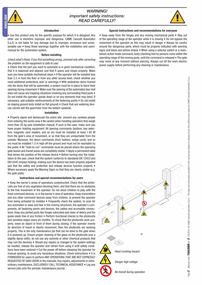
Special instructions and recommendations for everyone
• Keep away from the hinges and any moving mechanical parts • Stay out of the operating range of the operator while it is moving • Do not oppose the movement of the operator as this may result in danger • Always be careful around the dangerous parts, which must be properly indicated with warning signs and black and yellow stripes • When using a selector switch or a main-tained-action mode command, keep checking that no persons come within the operating range of the moving parts, until the command is released • The gate may move at any moment without warning. Always cut off the main electric power supply before performing any cleaning or maintenance.
WARNING!important safety instructions:
READ CAREFULLY!
Hand crushing hazard
Danger high voltage
No transit during operation

13
45
2
Pag
e 33
-
Man
ual
cod
e: 1
19A
U3
5EN
119
AU
35
EN
ver
. 55
0
5/2
014
©
CA
ME c
ance
lli a
uto
mat
ici S
.p.A
. -
The
dat
a an
d in
form
atio
n p
rovi
ded
in t
his
man
ual
are
subje
ct t
o ch
ange
at a
ny t
ime
with
out
prior
not
ice
by
CA
ME C
ance
lli A
uto
mat
ici S
.p.a
.
EN
GLIS
H
With swing gates it is always advisable to install and electro-lock. This is to ensure a reliable closing and to protect the gearmotor’s inner workings.
But whereas with reversible operators it is merely advisable, with irreversible ones, beyond 2.5 m, it is obligatory.
KEY
This symbol indicates parts to read carefully.
⚠This symbol indicates parts about safety.
☞This symbol tells you what to say to the end users.
DESCRIPTION
The product consists of: a foundation box, a gearmotor and motion transmission arms.
Intended use
Designed to power swing gates for residential or condominium use.
Any installation and operation that differs from what is set out in this manual is prohibited.
Packing list
1. 1 x Gearmotor
2. 1 x UNI 5588 M10 nut
3. 1 x UNI 5739 M10 x 100 hex screw
4. 1 x Transmission lever
5. 1 x Installation manual
REGULATORY REFERENCES
Came Cancelli Automatici is a company with an ISO 9001-certified company quality management system and an ISO 14001-certified environmental
management system.
The product in question complies with the regulations referred to in the declaration of conformity.
Limits of use
Model FROG-A24 / FROG-A24E
Gate leaf length (m) 3.5 2.5 2.0
Gate leaf weight (kg) 400 600 800
Technical data
Type FROG-A24 / FROG-A24E
Protection rating (IP) 67
Power supply (V - 50/60 Hz) 230 AC
Motor power supply (V - 50/60 Hz) 24 DC
Current draw (A) 15 max.
Power (W) 180
Thrust (N) 320 max.
Opening time to 90° (sec) ADJUSTABLE
Duty Cycle (%) INTENSIVE USE
Operating temperature (°C) -20 - +55
Motor thermal protection (°C) -
Gear ratio 1/1152
Insulation class I
Weight (kg) 11.5

2
6
5
8
10
9
3
4
7
10 11
12
1
13
14 15
16
5
2
8
8
9
10
11
3
12
12
1
12
3
7
4
6
Pag
e 44
-
Man
ual
cod
e: 1
19A
U3
5EN
119
AU
35
EN
ver
. 55
0
5/2
014
©
CA
ME c
ance
lli a
uto
mat
ici S
.p.A
. -
The
dat
a an
d in
form
atio
n p
rovi
ded
in t
his
man
ual
are
subje
ct t
o ch
ange
at a
ny t
ime
with
out
prior
not
ice
by
CA
ME C
ance
lli A
uto
mat
ici S
.p.a
.
EN
GLIS
H
Example of a system
1. Gearmotor with foundation box
2. Control panel
3. Junction box
4. Key selector
5. Antenna
6. Flashing light
7. Photocells
8. Photocell posts
9. Latch
10. Inspection chamber
11. Drainage chamber
12. Mechanical stop
Description of the components
1. Gearmotor
2. Transmission lever
3. Gearmotor arm
4. Limit switch adjusting screw while closing
5. Couple release lever
6. Mounting bracket to gate
7. Limit switch adjusting screw while opening
8. Foundation box
9. Casing cover
10. Cover fixing screw
11. UNI 5588 M12 nut
12. UNI 6592 washer
13. Limit switch unit
14. Drainage hole
15. Hole for electrical cable routing.
16. Pin

67
330405
160
60
100
Pag
e 55
-
Man
ual
cod
e: 1
19A
U3
5EN
119
AU
35
EN
ver
. 55
0
5/2
014
©
CA
ME c
ance
lli a
uto
mat
ici S
.p.A
. -
The
dat
a an
d in
form
atio
n p
rovi
ded
in t
his
man
ual
are
subje
ct t
o ch
ange
at a
ny t
ime
with
out
prior
not
ice
by
CA
ME C
ance
lli A
uto
mat
ici S
.p.a
.
EN
GLIS
H
Dimensions (mm)
GENERAL INSTALLATION INSTRUCTIONS
⚠ Installation must be carried out by qualified and experienced personnel in compliance with applicable regulations.
Preliminary checks
⚠ Before installing the operator:
• Provide a suitable single-pole disconnection device, with a maximum of 3 mm between the contacts, to disconnect the power supply;
• Prepare suitable piping and ducts for routing the electrical cables, ensuring protection against mechanical damage;
• Prepare a drain pipe to prevent stagnation that may cause oxidation;
• Make sure that any connections within the container (made to ensure the continuity of the protection circuit) are fitted with additional insulation
compared to the other internal conductor parts;
• Make sure the gate structure is sturdy enough, that the hinges are in proper working order and that there is no friction between the moving and fixed parts;
• Make sure there are opening and closing mechanical stops,
Tools and materials
Make sure you have all the tools and materials you will need for the installation at hand to work in total safety and compliance with current standards and
regulations. The figure shows some examples of installer’s tools.
Types of cables and minimum thicknesses
Connection Cable type Cable length1 < 10 m
Cable length10 < 20 m
Cable length20 < 30 m
Control panel power supply 230 V
FROR CEI
20-22
IEC EN
50267-2-1
3G x 1.5 mm2 3G x 1.5 mm2 3G x 2.5 mm2
Motor power supply 24 V 2 x 1.5 mm2 2 x 1.5mm2 2 x 2.5 mm2
Flashing light 2 x 0.5 mm2 2 x 1 mm2 2 x 1.5 mm2
Photocell transmitters 2 x 0.5 mm2 2 x 0.5 mm2 2 x 0.5 mm2
Photocell receivers 4 x 0.5 mm2 4 x 0.5 mm2 4 x 0.5 mm2
Control and safety devices 2 x 0.5 mm2 2 x 0.5 mm2 2 x 0.5 mm2
End run 4 x 0.5 mm2 4 x 0.5 mm2 4 x 0.5 mm2
Encoder TWISTED max. 30 m
Antenna RG58 max. 10 m
N.B. : If the cables differ in length from what is shown in the table, the cable cross-section is determined according to the actual current draw of the devices
connected and according to the provisions of the IEC EN 60204-1 standard.
For connections that require several, sequential loads, the sizes given on the table must be re-evaluated based on actual power draw and distances. When
connecting products that are not specified in this manual, please refer to the documentation provided with said products.

500
650
500
24h
67 mm
ч
Pag
e 66
-
Man
ual
cod
e: 1
19A
U3
5EN
119
AU
35
EN
ver
. 55
0
5/2
014
©
CA
ME c
ance
lli a
uto
mat
ici S
.p.A
. -
The
dat
a an
d in
form
atio
n p
rovi
ded
in t
his
man
ual
are
subje
ct t
o ch
ange
at a
ny t
ime
with
out
prior
not
ice
by
CA
ME C
ance
lli A
uto
mat
ici S
.p.a
.
EN
GLIS
H
INSTALLATION
⚠ The following illustrations are only examples, given that the space for securing the operator and accessories varies depending on the overall dimensions.
The installation technician is responsible for choosing the most suitable solution.
the figures below illustrate the installation of the right-hand foundation box.
Laying the corrugated pipes and inspection chambers
Make the hole for the box.
Prepare the junction boxes and corrugated pipes necessary for connection to the inspection chamber and the drain pipe.
the number of tubes depends on the type of system installed and any accessories.
Installing the foundation box
Lean the box against the pillar making sure that the corrugated pipes and the drain pipe pass through the designated holes.
Fill the hole with concrete.
Position the box level with the ground and place the pin in line with the upper gate hinge. Wait at least 24h to cure.
Clean any remaining concrete from inside the box.
67 mm

Pag
e 77
-
Man
ual
cod
e: 1
19A
U3
5EN
119
AU
35
EN
ver
. 55
0
5/2
014
©
CA
ME c
ance
lli a
uto
mat
ici S
.p.A
. -
The
dat
a an
d in
form
atio
n p
rovi
ded
in t
his
man
ual
are
subje
ct t
o ch
ange
at a
ny t
ime
with
out
prior
not
ice
by
CA
ME C
ance
lli A
uto
mat
ici S
.p.a
.
EN
GLIS
H
Install the gate leaf, inserting the upper hinge.
Check that the leaf opens and closes without difficulty.
Carefully fix or weld the door to the gate fixing bracket.
figure direction: internal right side view.
Lubricate the foundation case pin, the latch and the gate bracket pin.

Pag
e 88
-
Man
ual
cod
e: 1
19A
U3
5EN
119
AU
35
EN
ver
. 55
0
5/2
014
©
CA
ME c
ance
lli a
uto
mat
ici S
.p.A
. -
The
dat
a an
d in
form
atio
n p
rovi
ded
in t
his
man
ual
are
subje
ct t
o ch
ange
at a
ny t
ime
with
out
prior
not
ice
by
CA
ME C
ance
lli A
uto
mat
ici S
.p.a
.
EN
GLIS
H
Open the leaf to simplify gearmotor installation and securing inside the foundation case.
Use studs and nuts (supplied).
M12 nutUNI 5588
RIGHT SIDELEFT SIDE
Securing the gearmotor
Fit the adjusting screw into the motor arm. The direction in which the screw must be installed depends on the position of the operator.
Securing the release
It is important to lubricate the release tab; follow the instructions in the manual of the device selected.
VIEWED FROM INSIDE

3
12
Pag
e 99
-
Man
ual
cod
e: 1
19A
U3
5EN
119
AU
35
EN
ver
. 55
0
5/2
014
©
CA
ME c
ance
lli a
uto
mat
ici S
.p.A
. -
The
dat
a an
d in
form
atio
n p
rovi
ded
in t
his
man
ual
are
subje
ct t
o ch
ange
at a
ny t
ime
with
out
prior
not
ice
by
CA
ME C
ance
lli A
uto
mat
ici S
.p.a
.
EN
GLIS
H
Lubricate the transmission lever and push it into the holes of the gearmotor arm and case lever.
110° maximum opening
Determining the end run points
During opening:
- open the leaves completely (the maximum aperture is 110 °);
- loosen the screw (1) until it makes contact with the case (3);
- Tighten the nut (2) to lock the screw into position.

1
32
Pag
e 1010
-
Man
ual
cod
e: 1
19A
U3
5EN
119
AU
35
EN
ver
. 55
0
5/2
014
©
CA
ME c
ance
lli a
uto
mat
ici S
.p.A
. -
The
dat
a an
d in
form
atio
n p
rovi
ded
in t
his
man
ual
are
subje
ct t
o ch
ange
at a
ny t
ime
with
out
prior
not
ice
by
CA
ME C
ance
lli A
uto
mat
ici S
.p.a
.
EN
GLIS
H
For electrical connection operations follow the information in the control panel technical documents (see table).
ELECTRICAL CONNECTIONS
Gearmotor Control panel
FROG-A24 ZL19N - ZL170N
FROG-A24E ZLJ14 - ZLJ24
During closing:
- close the leaves completely;
- loosen the adjusting screw (1) until it makes contact with the transmission lever (2);
- Tighten the nut (3) to lock the screw into position.

500
500 500
Pag
e 1111
-
Man
ual
cod
e: 1
19A
U3
5EN
119
AU
35
EN
ver
. 55
0
5/2
014
©
CA
ME c
ance
lli a
uto
mat
ici S
.p.A
. -
The
dat
a an
d in
form
atio
n p
rovi
ded
in t
his
man
ual
are
subje
ct t
o ch
ange
at a
ny t
ime
with
out
prior
not
ice
by
CA
ME C
ance
lli A
uto
mat
ici S
.p.a
.
EN
GLIS
H
FINAL OPERATIONS
Establishing slowdown points (only for FROG-A24)
The points where slowdown begins while opening and closing are detected via a magnetic field..
The procedure for determining these points must be repeated several times, or until the leaves begin slowing to 500 mm from the end run.
During opening.
Bring the leaves to about 500 mm from the end runs during opening, operating the gearmotor. On both gearmotors, place the microswitch near the magnet
attached below the motor shaft.
Magnet
Microswitch
Magnet
Microswitch
During closing.
Pag
e 1212
-
Man
ual
cod
e: 1
19A
U3
5EN
119
AU
35
EN
ver
. 55
0
5/2
014
©
CA
ME c
ance
lli a
uto
mat
ici S
.p.A
. -
The
dat
a an
d in
form
atio
n p
rovi
ded
in t
his
man
ual
are
subje
ct t
o ch
ange
at a
ny t
ime
with
out
prior
not
ice
by
CA
ME C
ance
lli A
uto
mat
ici S
.p.a
.
EN
GLIS
H
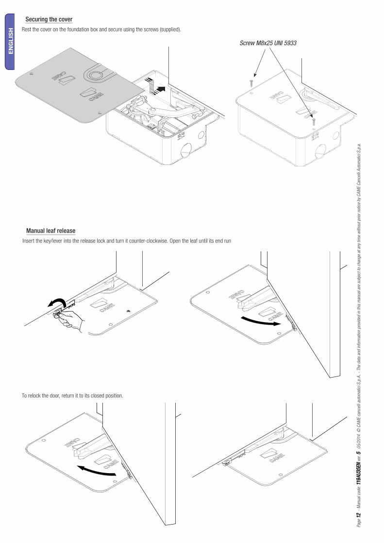
Screw M8x25 UNI 5933
Securing the cover
Rest the cover on the foundation box and secure using the screws (supplied).
To relock the door, return it to its closed position.
Manual leaf release
Insert the key/lever into the release lock and turn it counter-clockwise. Open the leaf until its end run
Pag
e 1313
-
Man
ual
cod
e: 1
19A
U3
5EN
119
AU
35
EN
ver
. 55
0
5/2
014
©
CA
ME c
ance
lli a
uto
mat
ici S
.p.A
. -
The
dat
a an
d in
form
atio
n p
rovi
ded
in t
his
man
ual
are
subje
ct t
o ch
ange
at a
ny t
ime
with
out
prior
not
ice
by
CA
ME C
ance
lli A
uto
mat
ici S
.p.a
.
EN
GLIS
H
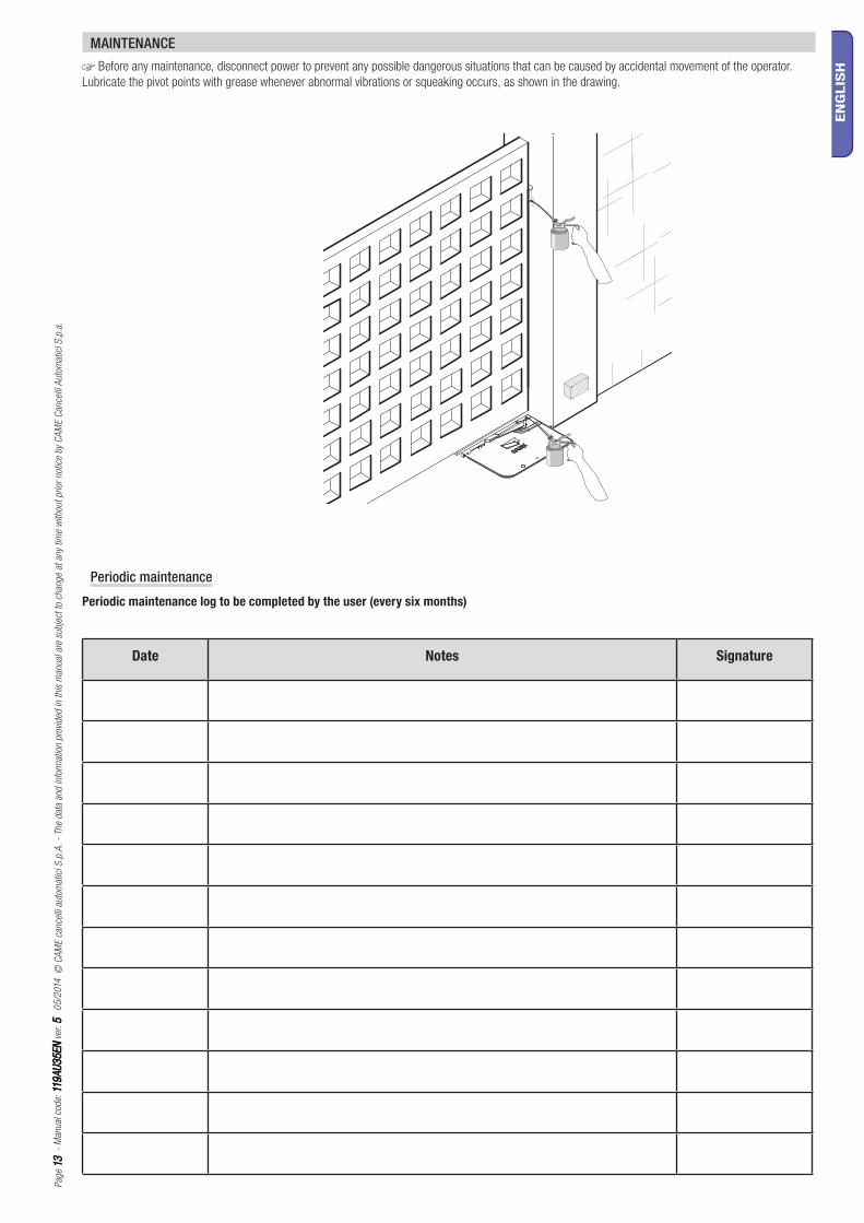
MAINTENANCE
☞ Before any maintenance, disconnect power to prevent any possible dangerous situations that can be caused by accidental movement of the operator.
Lubricate the pivot points with grease whenever abnormal vibrations or squeaking occurs, as shown in the drawing.
Date Notes Signature
Periodic maintenance
Periodic maintenance log to be completed by the user (every six months)

Pag
e 1414
-
Man
ual
cod
e: 1
19A
U3
5EN
119
AU
35
EN
ver
. 55
0
5/2
014
©
CA
ME c
ance
lli a
uto
mat
ici S
.p.A
. -
The
dat
a an
d in
form
atio
n p
rovi
ded
in t
his
man
ual
are
subje
ct t
o ch
ange
at a
ny t
ime
with
out
prior
not
ice
by
CA
ME C
ance
lli A
uto
mat
ici S
.p.a
.
EN
GLIS
H
Installation technician stamp Operator name
Date of intervention
Technician signature
Customer signature
Intervention carried out ________________________________________________________________________________________________________________________________________________________________________________________________________________________________________________________________________________________
Extraordinary maintenance log
Extraordinary maintenance
⚠ The table below is used to note any extraordinary maintenance, repairs or improvements carried out by specialist companies.
⚠Extraordinary maintenance must be carried out by specialist technicians.
Installation technician stamp Operator name
Date of intervention
Technician signature
Customer signature
Intervention carried out ________________________________________________________________________________________________________________________________________________________________________________________________________________________________________________________________________________________
Pag
e 1515
-
Man
ual
cod
e: 1
19A
U3
5EN
119
AU
35
EN
ver
. 55
0
5/2
014
©
CA
ME c
ance
lli a
uto
mat
ici S
.p.A
. -
The
dat
a an
d in
form
atio
n p
rovi
ded
in t
his
man
ual
are
subje
ct t
o ch
ange
at a
ny t
ime
with
out
prior
not
ice
by
CA
ME C
ance
lli A
uto
mat
ici S
.p.a
.
EN
GLIS
H
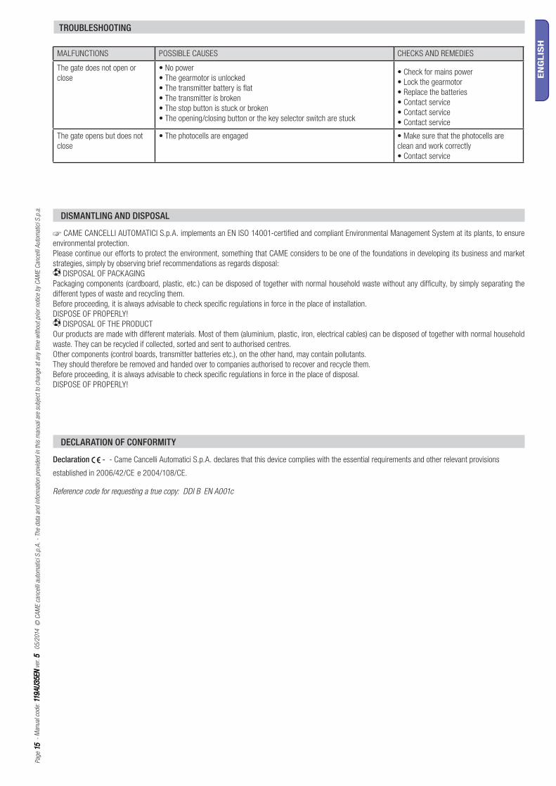
MALFUNCTIONS POSSIBLE CAUSES CHECKS AND REMEDIES
The gate does not open or
close
• No power
• The gearmotor is unlocked
• The transmitter battery is flat
• The transmitter is broken
• The stop button is stuck or broken
• The opening/closing button or the key selector switch are stuck
• Check for mains power
• Lock the gearmotor
• Replace the batteries
• Contact service
• Contact service
• Contact service
The gate opens but does not
close
• The photocells are engaged • Make sure that the photocells are
clean and work correctly
• Contact service
DISMANTLING AND DISPOSAL
☞ CAME CANCELLI AUTOMATICI S.p.A. implements an EN ISO 14001-certified and compliant Environmental Management System at its plants, to ensure
environmental protection.
Please continue our efforts to protect the environment, something that CAME considers to be one of the foundations in developing its business and market
strategies, simply by observing brief recommendations as regards disposal:
DISPOSAL OF PACKAGING
Packaging components (cardboard, plastic, etc.) can be disposed of together with normal household waste without any difficulty, by simply separating the
different types of waste and recycling them.
Before proceeding, it is always advisable to check specific regulations in force in the place of installation.
DISPOSE OF PROPERLY!
DISPOSAL OF THE PRODUCT
Our products are made with different materials. Most of them (aluminium, plastic, iron, electrical cables) can be disposed of together with normal household
waste. They can be recycled if collected, sorted and sent to authorised centres.
Other components (control boards, transmitter batteries etc.), on the other hand, may contain pollutants.
They should therefore be removed and handed over to companies authorised to recover and recycle them.
Before proceeding, it is always advisable to check specific regulations in force in the place of disposal.
DISPOSE OF PROPERLY!
DECLARATION OF CONFORMITY
Declaration - - Came Cancelli Automatici S.p.A. declares that this device complies with the essential requirements and other relevant provisions
established in 2006/42/CE e 2004/108/CE.
Reference code for requesting a true copy: DDI B EN A001c
TROUBLESHOOTING

www. came.comwww. came.com
CAME Cancelli Automatici S.p.a.CAME Cancelli Automatici S.p.a.
Via Martiri Della Libertà, 15
31030 Dosson Di Casier Dosson Di Casier (Tv)
(+39) 0422 4940
(+39) 0422 4941
Assistenza Tecnica/Numero Verde 800 295830Assistenza Tecnica/Numero Verde 800 295830
IT • Per ogni ulteriore informazione su azienda, prodotti e assistenza nella vostra lingua:
EN • For any further information on company, products and assistance in your language:
FR • Pour toute autre information sur la société, les produits et l’assistance dans votre langue :
DE • Weitere Infos über Unternehmen, Produkte und Kundendienst bei:
ES • Por cualquier información sobre la empresa, los productos y asistencia en su idioma:
NL • Voor meer informatie over het bedrijf, de producten en hulp in uw eigen taal:
PT • Para toda e qualquer informação acerca da empresa, de produtos e assistência técnica, em sua língua:
PL • Wszystkie inne informacje dotyczące fi rmy, produktów oraz usług i pomocy technicznej w Waszym języku znajdują się na stronie:
RU • Для получения дополнительной информации о компании, продукции и сервисной поддержке на вашем языке:
HU • A vállalatra, termékeire és a műszaki szervizre vonatkozó minden további információért az Ön nyelvén:
HR • Za sve dodatne informacije o poduzeću, proizvodima i tehničkoj podršci:
UK • Для отримання будь-якої іншої інформації про компанію, продукцію та технічну підтримку:
Englis
hEn
glis
h -
Man
ual
cod
e: 1
19A
U3
5EN
119
AU
35
EN
ver
. 55
0
5/2
014
© C
AM
E c
ance
lli a
uto
mat
ici S
.p.A
.
The
dat
a an
d in
form
atio
n p
rovi
ded
in t
his
man
ual
are
subje
ct t
o ch
ange
at a
ny t
ime
with
out
prior
not
ice
by
CA
ME C
ance
lli A
uto
mat
ici S
.p.a
.