Installation Manual · BS EN 55014-1: 2017: Electromagnetic Compatibility - Requirements for...
42
System Boiler Range System, Systempac & Slimline Systempac Models Installation Manual
Transcript of Installation Manual · BS EN 55014-1: 2017: Electromagnetic Compatibility - Requirements for...
file:///Users/pjaspare/Downloads/LDS7_FINAL.pdf
System Boiler Range System, Systempac & Slimline Systempac Models
Installation Manual
1
Contents
FoReWoRD
We would like to thank you for purchasing a high efficiency Firebird condensing liquid fuel boiler with an Elco low Nox burner. This instruction manual is produced for the reference and guidance of qualified installation engineers, preferably OFTEC (Oil Firing Technical Association) registered. EU legislation governs the manufacture, operation and efficiency of all domestic central heating oil boilers. Our boilers and burners are supplied as matched units.
PAgE
1. saFety .................................................................................................................................................................................................................................................. 2
2. stanDaRDs & Regulations ................................................................................................................................................................... 3 2.1 Condensate Disposal ....................................................................................................................................................................................... 4 2.2 Flue Regulations ....................................................................................................................................................................................................... 7 2.3 Flue Systems ..................................................................................................................................................................................................................... 10 2.4 Liquid Fuel Supply ................................................................................................................................................................................................... 11
3. systeM BoileR 3.1 Householder/End User Information ......................................................................................................................................... 12 3.2 Installer guidelines ............................................................................................................................................................................................... 14 3.3 Technical Details ....................................................................................................................................................................................................... 19
4 . systeMPaC 4.1 Householder/End User Information ......................................................................................................................................... 22 4.2 Installer guidelines ............................................................................................................................................................................................... 23 4.3 Technical Details ....................................................................................................................................................................................................... 27
5. sliMline systeMPaC 5.1 Householder/End User Information ......................................................................................................................................... 30 5.2 Installer guidelines ............................................................................................................................................................................................... 31 5.3 Technical Details ....................................................................................................................................................................................................... 34
6. CoMMissioning ............................................................................................................................................................................................................... 37
7. seRviCing ....................................................................................................................................................................................................................................... 38
8. teRMs & ConDitions oF WaRRanty ....................................................................................................................................... 39
9. PRoDuCt FiCHe .................................................................................................................................................................................................................. 40
1
HealtH & saFety inFoRMation
tHis PRoDuCt Has Been DesigneD to tHe FolloWing stanDaRDs:
this equipment complies with the low voltage Directive 2014/35/eu and Directive 2014/30/eu.
eMC - conformity was demonstrated by meeting the following standards:
BS EN 55014-2: 2015: Electromagnetic Compatibility - Requirements for Household Appliances, Electric Tools and Similar Apparatus - Part 1: Emission
BS EN 55014-1: 2017: Electromagnetic Compatibility - Requirements for Household Appliances, Electric Tools and Similar Apparatus - Part 2: Immunity - Product Family Standard
BS EN 61000-3-2: 2014: Electromagnetic Compatibility (EMC) Part 3-2: Limits - Limits for Harmonic Current Emissions (equipment input current <16 A per phase)
BS EN 61000-3-3: 2013: Electromagnetic Compatibility (EMC) Part 3-3: Limits - Limitation of Voltage Changes, Voltage Fluctuations and Flicker in Public Low-voltage Supply Systems (equipment with rated current <16 A per phase and not subject to conditional connection)
2
saFety
The installer should be aware of his/her responsibilities under the current, local Health and Safety at Work Act. The interests of safety are best served if the boiler is installed and commissioned by a competent, qualified engineer, preferably OFTEC trained and registered. A Building Notice may be required in England and Wales and other parts of the United Kingdom.
Under the Consumer Protection Act 1987 (UK), section 6 of the Health and Safety Act 1974 (UK) and the Safety, Health and Welfare at Work Act 2005 (ROI), we are required to provide information on substances hazardous to health.
insulation anD sealsCeramic Fibre, Alumino - Silicone Fibre material are used for boards, ropes and gaskets. Known hazards are that people may suffer reddening and itching of the skin. Fibre entering the eye will cause foreign body irritation. It may also cause irritation to the respiratory tract.
Precautions should be taken by people with a history of skin complaints or who may be particularly susceptible to irritation. High dust levels are only likely to arise following harsh abrasion. Suitable personal protective equipment should be worn where appropriate.
generally, normal handling and use will not give discomfort. Follow good hygiene practices, wash hands before consuming food, drink or using the toilet.
First Aid - medical attention should be sought following eye contact or prolonged reddening of the skin.
The small quantities of adhesives and sealants used in the product are cured. They present no known hazards when used in the manner for which they are intended.
Fuel sPillage1. Switch off all electrical and other ignition sources.
2. Remove all contaminated clothing to safeguard against fire risk and skin damage. Wash affected skin thoroughly with soap and water and remove clothing to a safe well ventilated area and allow to air before cleaning.
3. Contain and smother the spill using sand or other suitable oil absorbent media or non-combustible material.
4. Do not allow fuel to escape into drains or water courses. If this happens, contact the relevant authorities in your area.
5. Consult local authority about disposal of contaminated soil.
saFetySafe use of Kerosene. These fuels give off a flammable vapour when heated moderately. Vapour ignites easily, burns intensely and may cause explosion. The vapour can follow along at ground level for considerable distances from open containers and spillages collecting as an explosive mixture in drains, cellars, etc.
Fuels remove natural oils and fats from the skin and this may cause irritation and cracking of skin. Barrier cream containing lanolin is highly recommended together with good personal hygiene and where necessary appropriate persona protection equipment (P.P.E.).
gas oil may also cause irreversible damage to health on prolonged or repeated skin contact.
Always store fuels in a properly constructed and labelled tank. Always handle fuel in open air or well ventilated space away from sources of ignition and refrain from smoking.
Always drain fuel using a proper fuel retriever, funnel or mechanical siphon. Never apply heat to a fuel tank, container or pipework. Never siphon fuel through tube by mouth.
Avoid inhaling fuel vapour as this can cause light headedness and seriously impair judgement.
FiRst aiDIf fuel is accidentally swallowed:
* Seek medical attention immediately.Do NOT induce vomiting.
If fuel is splashed into eyes:* Wash out with running water for at least ten
minutes and seek medical attention.
safety - conformity was demonstrated by meeting the following standards:
EN60335-1: 2012 + A13: 2017: Household and Similar Electrical Appliances - Safety - Part 1: general Requirements
EN60335-2-102: 2006 + A2: 2016: Household and Similar Electrical Appliances - Safety - Part 2-102: Particular Requirements for gas, Oil and Solid-fuel Burning Appliances having Electrical Connections
2
3
stanDaRDs & Regulations
Regional water supply (water fittings) regulations/byelaws. Regional control of pollution (oil storage) regulations.
oFteC also publish excellent guides including:• OFTECTechnicalBookOne-Safeworkingforoil
firing and delivery technicians.• OFTECTechnicalBookTwo-Domestic&light
commercial servicing and commissioning. • OFTECTechnicalBookThree-Domesticand
commercialrequirementsforoilstorage&supplyequipment.
• OFTECTechnicalBookFour-Oilfiredappliance&system installation requirements.
COPIES OF BRITISH STANDARDS MAyBE PURCHASED DIRECT FROM:
Bsi (Customer services),389 Chiswick High Rd., london W4 4al.
tel.: +44 (0)345 0869001International and EC Standards are
also available from above.
OFTEC PUBLICATIONS ARE AVAILABLE FROM:oFteC, oil Firing technical association,
Foxwood House, Dobbs lane,Kesgrave, ipswich, iP5 2QQ.
www.oftec.org
BoileR installation:Other than special considerations for condensate removal and plume dispersal, the installation of liquid fuel fired condensing boilers is the same as for non-condensing oil fired boilers.
BS 5410:1: 2014 gives the requirements for domestic boiler and liquid fuel storage installations.
If an appliance is to be installed inside a building or within a restricted area externally, a carbon monoxide detector alarm conforming to BS EN 50291-1: 2018 should be installed in accordance with the manufacturer’s instructions.
For condensing boilers, the same requirements apply for installation with regard to cleaning and flushing and providing inhibitors, as are followed for any other boiler. Manufacturer’s instructions must always be followed together with the requirements of BSEN12828:2012+A1:2014&BSEN12831-1:2017and the statutory requirements of the Building Regulations.
to ensure the highest standards of installation & safety, it is important that the boiler be installed in compliance with the following regulations where applicable. it is the responsibility of the installer and everyone concerned with any aspect of installation, to ensure that all applicable standards and regulations are fully adhered to.
The following is a list of some of the applicable standards and regulations. Please always check for the most up to date version.
All relevant building standards and regulations for Ireland, England, Scotland, Wales and Northern Ireland.
BS 5410-1: 2014 Code of practice for oil firing. Installations up to 45kW output capacity for space heating and hot water supply purposes.
BS 5410-2:2018 Code of practice for liquid fuel firing. Non-domestic installations.
BS 799-5: 2010 Oil burning equipment. Carbon steel oil storage tanks. Specification.
BS EN 303-1: 2017 Heating boilers. Heating boilers with forced draught burners. Terminology, general requirements, testing and marking.
BS EN 12828: 2012 Heating systems in buildings. Design + A1: 2014 for water based heating systems.
BS 7074-1: 1989 Application, selection and installation of expansion vessels and ancillary equipment for sealed water systems. Code of practice for domestic heating and hot water supply.
BS 7593: 2006 Code of practice for treatment of water in domestic hot water central heating systems.
BS EN 13502: 2002 Chimneys. Requirements and test methods for clay/ceramic flue terminals.
BS EN 1856-1: 2009 Chimneys. Requirements for metal chimneys. System chimney products.
BS 8558: 2015 guide to the design, installation, testing and maintenance of services supplying water for domestic use within buildings and their curtilages. Complementary guidance to BS EN 806.
BS 7671: 2018 Requirements for Electrical Installations. IET Wiring Regulations.
BS EN 304: 2017 Heating boilers. Test code for heating boilers for atomizing oil burners.
2
4
2.1 stanDaRDs & Regulations - ConDensate DisPosal
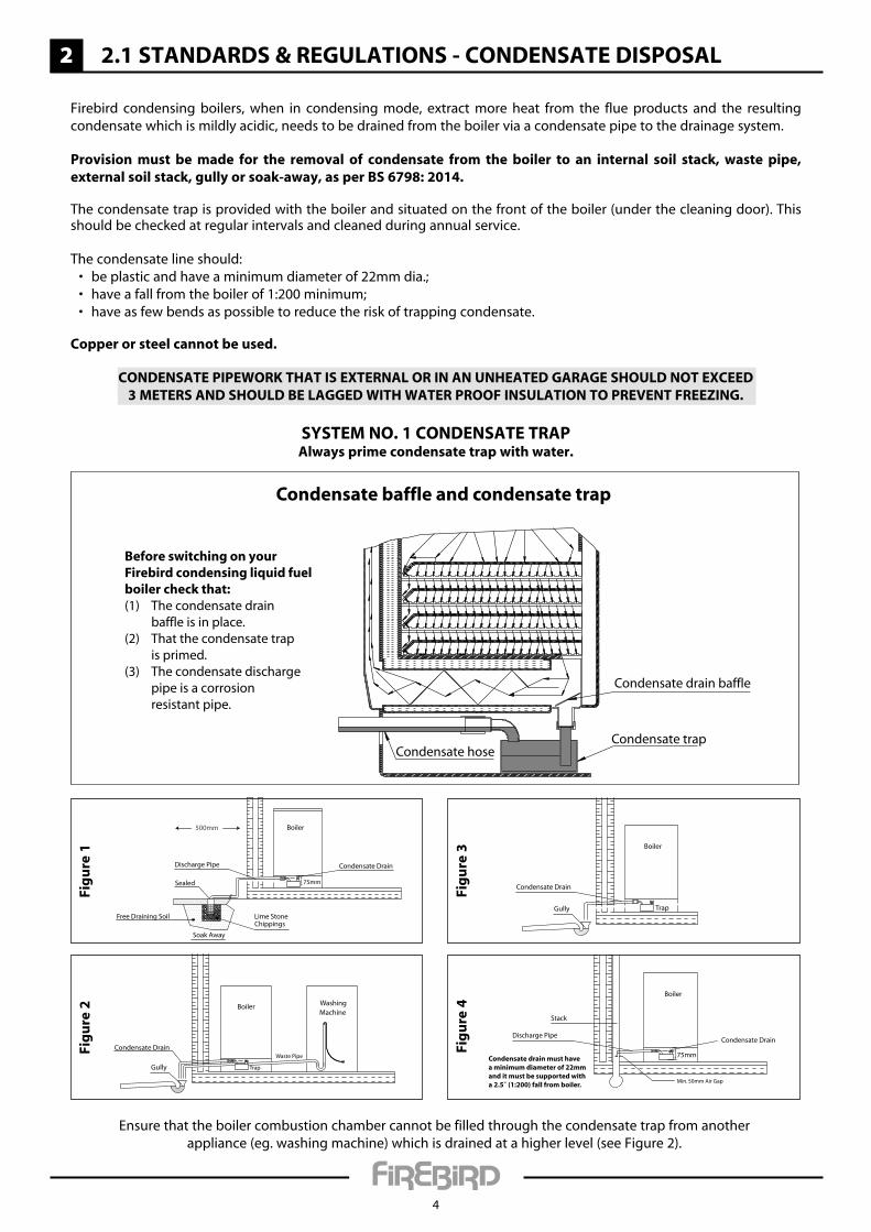
Firebird condensing boilers, when in condensing mode, extract more heat from the flue products and the resulting condensate which is mildly acidic, needs to be drained from the boiler via a condensate pipe to the drainage system.
Provision must be made for the removal of condensate from the boiler to an internal soil stack, waste pipe, external soil stack, gully or soak-away, as per Bs 6798: 2014.
The condensate trap is provided with the boiler and situated on the front of the boiler (under the cleaning door). This should be checked at regular intervals and cleaned during annual service.
The condensate line should: • beplasticandhaveaminimumdiameterof22mmdia.; • haveafallfromtheboilerof1:200minimum; • haveasfewbendsaspossibletoreducetheriskoftrappingcondensate.
Copper or steel cannot be used.
ConDensate PiPeWoRK tHat is exteRnal oR in an unHeateD gaRage sHoulD not exCeeD3 MeteRs anD sHoulD Be laggeD WitH WateR PRooF insulation to PRevent FReezing.
Boiler
Sealed
Condensate DrainDischarge Pipe
75mm
Soak Away
Lime Stone Chippings
Free Draining Soil
500mm
Fig
ure
1
Boiler
Gully
Condensate Drain
Washing Machine
Trap
Waste Pipe
Fig
ure
2
Boiler
Gully
Condensate Drain
Trap
Fig
ure
3
Condensate drain must havea minimum diameter of 22mmand it must be supported witha 2.5˚ (1:200) fall from boiler.
Boiler
Stack
Condensate DrainDischarge Pipe
75mm
Min. 50mm Air Gap
Fig
ure
4
Ensure that the boiler combustion chamber cannot be filled through the condensate trap from anotherappliance (eg. washing machine) which is drained at a higher level (see Figure 2).
systeM no. 1 ConDensate tRaPalways prime condensate trap with water.
Condensate drain baffle
Condensate baffle and condensate trap
Condensate trapCondensate hose
Before switching on your Firebird condensing liquid fuel boiler check that:(1) The condensate drain baffle is in place.(2) That the condensate trap is primed.(3) The condensate discharge pipe is a corrosion resistant pipe.
2
5
2.1 stanDaRDs & Regulations - ConDensate DisPosal
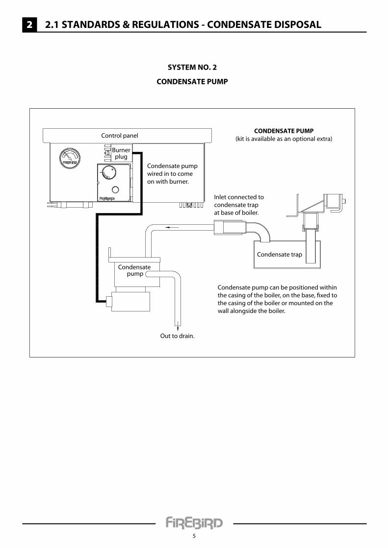
systeM no. 2
ConDensate PuMP
Condensate pump can be positioned withinthe casing of the boiler, on the base, fixed tothe casing of the boiler or mounted on thewall alongside the boiler.
Condensate pumpwired in to comeon with burner.
Inlet connected tocondensate trapat base of boiler.
Out to drain.
Control panel
Condensate pump
Burnerplug
Condensate trap
ConDensate PuMP(kit is available as an optional extra)
2
6
2.1 stanDaRDs & Regulations - ConDensate DisPosal
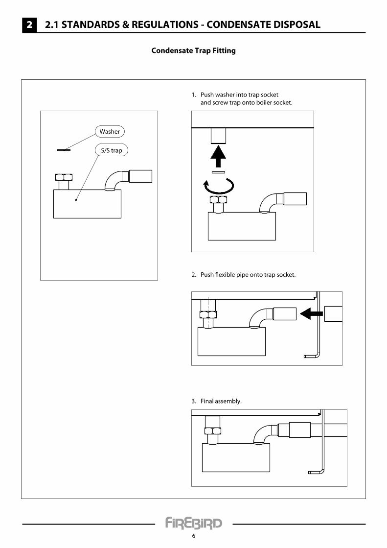
Condensate trap Fitting
1. Push washer into trap socket and screw trap onto boiler socket.
2. Push flexible pipe onto trap socket.
3. Final assembly.
Washer
S/S trap
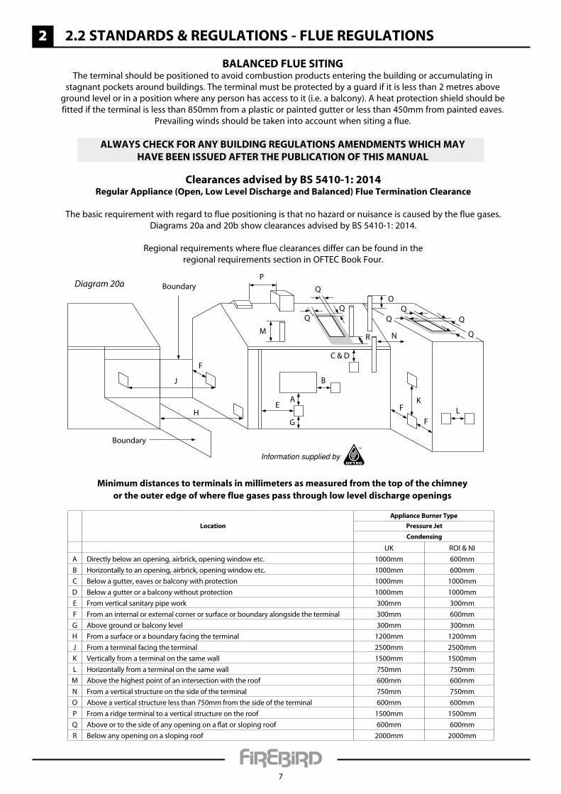
BalanCeD Flue sitingThe terminal should be positioned to avoid combustion products entering the building or accumulating in
stagnant pockets around buildings. The terminal must be protected by a guard if it is less than 2 metres above ground level or in a position where any person has access to it (i.e. a balcony). A heat protection shield should be fitted if the terminal is less than 850mm from a plastic or painted gutter or less than 450mm from painted eaves.
Prevailing winds should be taken into account when siting a flue.
alWays CHeCK FoR any BuilDing Regulations aMenDMents WHiCH MayHave Been issueD aFteR tHe PuBliCation oF tHis Manual
2
7
2.2 stanDaRDs & Regulations - Flue Regulations
Clearances advised by Bs 5410-1: 2014Regular appliance (open, low level Discharge and Balanced) Flue termination Clearance
The basic requirement with regard to flue positioning is that no hazard or nuisance is caused by the flue gases. Diagrams 20a and 20b show clearances advised by BS 5410-1: 2014.
Regional requirements where flue clearances differ can be found in theregional requirements section in OFTEC Book Four.
A
G
E
B
C & D
KF
FL
N
O
P
H
J
Boundary
Boundary
F
Q
QQ Q
Q
Q
Q
R
Pressure JetLocationAppliance Burner Type
Condensing
UK ROI & NI
A Directly below an opening, airbrick, opening window etc. 1000mm 600mm
B Horizontally to an opening, airbrick, opening window etc. 1000mm 600mm
C Below a gutter, eaves or balcony with protection 1000mm 1000mm
D Below a gutter or a balcony without protection 1000mm 1000mm
E From vertical sanitary pipe work 300mm 300mm
F From an internal or external corner or surface or boundary alongside the terminal 300mm 600mm
G Above ground or balcony level 300mm 300mm
H From a surface or a boundary facing the terminal 1200mm 1200mm
J From a terminal facing the terminal 2500mm 2500mm
K Vertically from a terminal on the same wall 1500mm 1500mm
L Horizontally from a terminal on the same wall 750mm 750mm
M Above the highest point of an intersection with the roof 600mm 600mm
N From a vertical structure on the side of the terminal 750mm 750mm
O Above a vertical structure less than 750mm from the side of the terminal 600mm 600mm
P From a ridge terminal to a vertical structure on the roof 1500mm 1500mm
Q Above or to the side of any opening on a flat or sloping roof 600mm 600mm
R Below any opening on a sloping roof 2000mm 2000mm
M
Minimum distances to terminals in millimeters as measured from the top of the chimneyor the outer edge of where flue gases pass through low level discharge openings
Diagram 20a
2
8
2.2 stanDaRDs & Regulations - Flue Regulations
BalanCeD Flue BoileRs
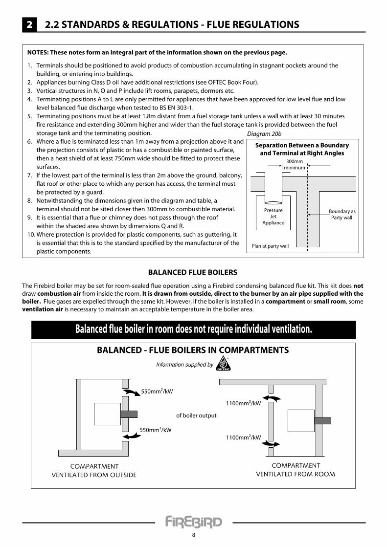
The Firebird boiler may be set for room-sealed flue operation using a Firebird condensing balanced flue kit. This kit does not draw combustion air from inside the room. it is drawn from outside, direct to the burner by an air pipe supplied with the boiler. Flue gases are expelled through the same kit. However, if the boiler is installed in a compartment or small room, some ventilation air is necessary to maintain an acceptable temperature in the boiler area.
550mm²/kW
550mm²/kW
1100mm²/kW
1100mm²/kW
of boiler output
Balanced flue boiler in room does not require individual ventilation.
BalanCeD - Flue BoileRs in CoMPaRtMents
notes: these notes form an integral part of the information shown on the previous page.
1. Terminals should be positioned to avoid products of combustion accumulating in stagnant pockets around the building, or entering into buildings.
2. Appliances burning Class D oil have additional restrictions (see OFTEC Book Four).3. Vertical structures in N, O and P include lift rooms, parapets, dormers etc.4. Terminating positions A to L are only permitted for appliances that have been approved for low level flue and low
level balanced flue discharge when tested to BS EN 303-1.5. Terminating positions must be at least 1.8m distant from a fuel storage tank unless a wall with at least 30 minutes
fire resistance and extending 300mm higher and wider than the fuel storage tank is provided between the fuel storage tank and the terminating position.
6. Where a flue is terminated less than 1m away from a projection above it and the projection consists of plastic or has a combustible or painted surface, then a heat shield of at least 750mm wide should be fitted to protect these surfaces.
7. If the lowest part of the terminal is less than 2m above the ground, balcony, flat roof or other place to which any person has access, the terminal must be protected by a guard.
8. Notwithstanding the dimensions given in the diagram and table, a terminal should not be sited closer then 300mm to combustible material.
9. It is essential that a flue or chimney does not pass through the roof within the shaded area shown by dimensions Q and R.
10. Where protection is provided for plastic components, such as guttering, it is essential that this is to the standard specified by the manufacturer of the plastic components.
Separation Between a Boundaryand Terminal at Right Angles
Boundary asParty wall
PressureJet
Appliance
Plan at party wall
300mmminimum
Diagram 20b
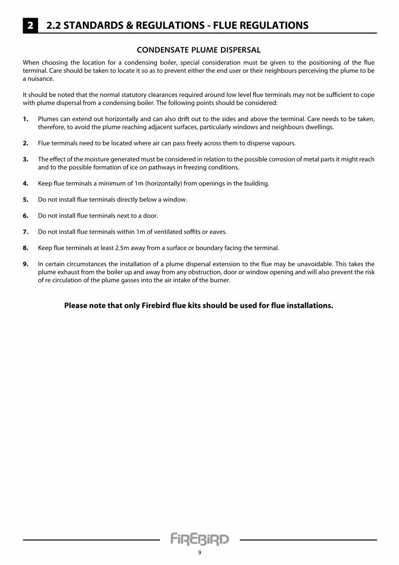
Condensate Plume disPersalWhen choosing the location for a condensing boiler, special consideration must be given to the positioning of the flue terminal. Care should be taken to locate it so as to prevent either the end user or their neighbours perceiving the plume to be a nuisance.
It should be noted that the normal statutory clearances required around low level flue terminals may not be sufficient to cope with plume dispersal from a condensing boiler. The following points should be considered:
1. Plumes can extend out horizontally and can also drift out to the sides and above the terminal. Care needs to be taken, therefore, to avoid the plume reaching adjacent surfaces, particularly windows and neighbours dwellings.
2. Flue terminals need to be located where air can pass freely across them to disperse vapours.
3. The effect of the moisture generated must be considered in relation to the possible corrosion of metal parts it might reach and to the possible formation of ice on pathways in freezing conditions.
4. Keep flue terminals a minimum of 1m (horizontally) from openings in the building.
5. Do not install flue terminals directly below a window.
6. Do not install flue terminals next to a door.
7. Do not install flue terminals within 1m of ventilated soffits or eaves.
8. Keep flue terminals at least 2.5m away from a surface or boundary facing the terminal.
9. In certain circumstances the installation of a plume dispersal extension to the flue may be unavoidable. This takes the plume exhaust from the boiler up and away from any obstruction, door or window opening and will also prevent the risk of re circulation of the plume gasses into the air intake of the burner.
Please note that only Firebird flue kits should be used for flue installations.
2
9
2.2 stanDaRDs & Regulations - Flue Regulations
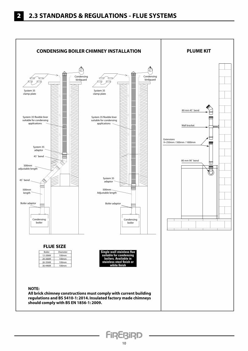
PLUME KIT
80 mm 45˚ bend
Wall bracket
ExtensionsX=250mm / 500mm / 1000mm
80 mm 90˚ bend
CONDENSING BOILER CHIMNEY INSTALLATION
System 35 flexible linersuitable for condensing
applications
System 35adaptor
45˚ bend
500mmadjustable length
45˚ bend
500mmlength
Boiler adaptor
Condensingbirdguard
Condensingbirdguard
System 35clamp plate
System 35clamp plate
System 35 flexible linersuitable for condensing
applications
System 35adaptor
500mmAdjustable length
Boiler adaptor
Condensingboiler
Condensingboiler
NOTE:All brick chimney constructions must comply with current building regulations and BS 5410-1: 2014. Insulated factory made chimneys should comply with BS EN 1856-1: 2009.
Single wall stainless �ue suitable for condensing
boilers. Available in stainless steel nish or
white nish
Boiler
12-20kW
20-26kW
26-35kW
36-44kW
Diameter
100mm
100mm
100mm
100mm
FLUE SIZE
2
10
2.3 stanDaRDs & Regulations - Flue systeMs

2
11
2.4 stanDaRDs & Regulations - liQuD Fuel suPPly
Fuel stoRage tanK sittingConsult OFTEC Manuals
It is unlikely that a fire will start at a fuel tank. However, the stored fuel must be protected from a fire or heat source that originates nearby. For this reason fuel tanks of up to 3,500 litres should be separated from openings, other than airbricks, in the building by a minimum of 1.8m and a non-fire rated boundary by a minimum of 760mm. Where this cannot be achieved, a 30 minute fire rated barrier should be constructed between the hazard and the tank, which extends a minimum of 300mm higher and 300mm past each end of the tank. Note that a minimum separation distance should be maintained between a flue exit and fire barrier (see page 7 (flue regulations)).
Steel tanks must be mounted on brick or block piers with a waterproof membrane between the piers of the tank.
Fuel storage tanks should not be sited within 1.8m of boiler flue outlets.
Do not allow household waste or hot ashes container in vicinity of oil storage tank or boiler flue outlet.
FlexiBle oil PiPe(s)A flexible burner oil hose is supplied with the boiler which must be wholly contained within the appliance case.
Please note: a filter must not be fitted inside the boiler and all joints in the oil line must be oil tight. soldered joints are not permissible. Before connecting to the boiler, always flush the complete oil supply line and ensure that the liquid fuel supply is completely clean and free of any dirt or foreign matter.
oil line ConFiguRationRefer to burner manual section on Hydraulic Systems for:•Twopipesystems.•Pipesizing&distance.•Tankheights.•Pumppriming.
Regulations & stanDaRDsPlease consult all local and regional regulations, relevant to water resources (control of pollution and oil storage) as well as OFTEC Book Three.
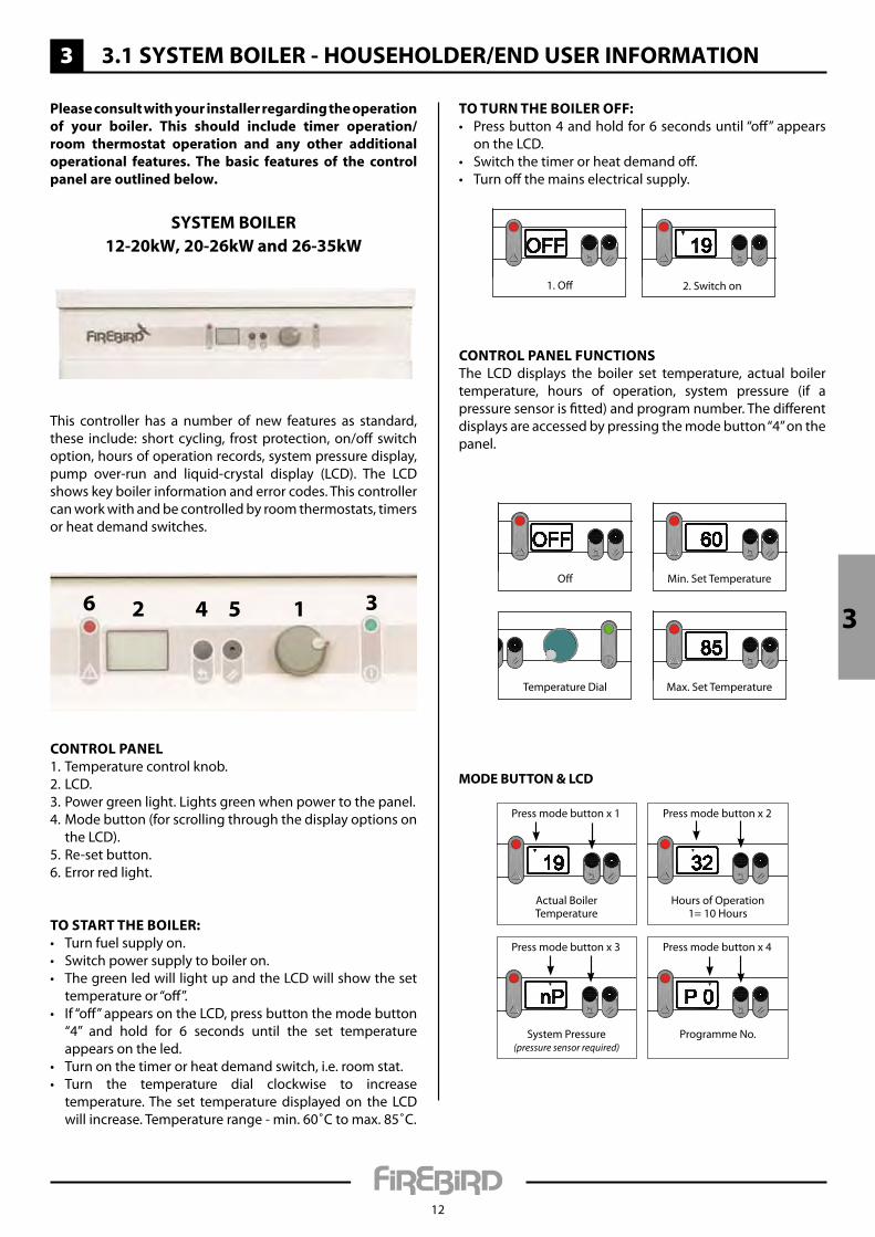
TO TURN THE BOILER OFF:• Pressbutton4andholdfor6secondsuntil“off”appears
on the LCD.• Switchthetimerorheatdemandoff.• Turnoffthemainselectricalsupply.
CONTROL PANEL FUNCTIONSThe LCD displays the boiler set temperature, actual boilertemperature, hours of operation, system pressure (if a pressuresensorisfitted)andprogramnumber.Thedifferentdisplaysareaccessedbypressingthemodebutton“4”onthepanel.
3
12
3.1 systeM BoileR - HouseHolDeR/enD useR inFoRMation
CONTROL PANEL1.Temperaturecontrolknob.2. LCD.3.Powergreenlight.Lightsgreenwhenpowertothepanel.4. Mode button (for scrolling through the display options on
the LCD).5. Re-set button.6.Errorredlight.
TO START THE BOILER:• Turnfuelsupplyon.• Switchpowersupplytoboileron.• ThegreenledwilllightupandtheLCDwillshowtheset
temperatureor“off”.• If“off”appearsontheLCD,pressbuttonthemodebutton
“4” and hold for 6 seconds until the set temperatureappears on the led.
• Turnonthetimerorheatdemandswitch,i.e.roomstat.• Turn the temperature dial clockwise to increase
temperature.The set temperaturedisplayedon the LCDwillincrease.Temperaturerange-min.60˚Ctomax.85˚C.
This controller has a number of new features as standard,these include: short cycling, frostprotection,on/offswitchoption, hours of operation records, system pressure display, pump over-run and liquid-crystal display (LCD). The LCDshowskeyboilerinformationanderrorcodes.Thiscontrollercan work with and be controlled by room thermostats, timers or heat demand switches.
1 3546 2
1.Off 2. Switch on
Min.SetTemperature
TemperatureDial Max.SetTemperature
Off
Actual BoilerTemperature
Pressmodebuttonx1
Hours of Operation1=10Hours
Pressmodebuttonx2
SystemPressure(pressure sensor required)
Pressmodebuttonx3
ProgrammeNo.
Pressmodebuttonx4
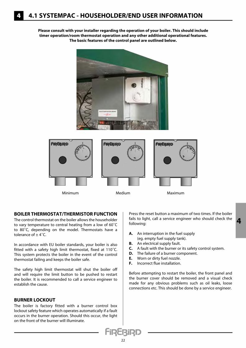
Please consult with your installer regarding the operation of your boiler. this should include timer operation/room thermostat operation and any other additional operational features. the basic features of the control panel are outlined below.
systeM BoileR12-20kW, 20-26kW and 26-35kW
MODE BUTTON & LCD
3

3
13
3.1 systeM BoileR - HouseHolDeR/enD useR inFoRMation
ERROR DISPLAy AND RE-SETWarning: Should an error appear on the control panel display, consult your service engineer or the Firebird technical department before attempting to re-set the error.
systeM BoileR 36-44kW
BoileR tHeRMostat/tHeRMistoR FunCtionThe control thermostat on the boiler allows the householder to vary temperature to central heating from a low of 60˚C to 80˚C, depending on the model. Thermostats have a tolerance of ± 4˚C.
In accordance with EU boiler standards, your boiler is also fitted with a safety high limit thermostat, fixed at 110˚C. This system protects the boiler in the event of the control thermostat failing and keeps the boiler safe.
The safety high limit thermostat will shut the boiler off and will require the limit button to be pushed to restart the boiler. It is recommended to call a service engineer to establish the cause.
BuRneR loCKoutThe boiler is factory fitted with a burner control box lockout safety feature which operates automatically if a fault occurs in the burner operation. Should this occur, the light on the front of the burner will illuminate.
Press the reset button a maximum of two times. If the boiler fails to light, call a service engineer who should check the following:
a. An interruption in the fuel supply (eg. empty fuel supply tank).B. An electrical supply fault.C. A fault with the burner or its safety control system.D. The failure of a burner component.e. Worn or dirty fuel nozzle.F. Incorrect flue installation.
E1Thermistorfault.E2 Flue thermistor fault (if flue thermistor installed into
flue).E5 Burner lockout. Burner fault.
NOTE: In the event of the boiler overheating, the limit thermostatwillshutoffpowertothepanel.
ERROR DISPLAy
Tore-setandclearanerrorfromthecontrolpanel:• Use the tipof apinand insert into the re-setbutton“5”onthepanel.Pressandholduntiltheerrorclears.
• ForE5(burnerlockout),pressthelockoutbuttonontheburnerfirst.Thiswillnotbelitupasnormal,thenpresstheresetbutton“3”onthepanel.
RE-SET CONTROLLER
3
Minimum MaximumMedium
3
14
3.2 systeM BoileR - installeR guiDelines
Please note the following important points before commencing installation.
installation should only be carried out by a competent, qualified engineer, preferably oFteC registered, familiar with the installation of the Firebird boilers referred to in this manual.
WaRningThe manufacturer cannot accept responsibility for any damage to persons, animals or property due to error in installation or in the burner adjustment or due to improper or unreasonable use or non-observance of the technical instruction enclosed with the burner, or due to the intervention of unqualified personnel.
Positioning tHe BoileRCompliance guide to part L now states that when installing a boiler on a new or existing system, the system should be cleaned, flushed and then protected with a suitable protection inhibitor.
Ensure that adequate clearance is available for making the water and flue connections.
The boiler is serviced from the front and a clearance of 750mm must be available at the front of the boiler.
No special hearth is required as the boiler is fully insulated, but the floor must be level and capable of supporting the weight of the boiler and its water content.
Sound levels must also be a consideration. Whilst Firebird condensing liquid fuel boilers are one of the quietest boilers on the market, some householders are particularly sensitive.
a suitable corrosion inhibitor must be added to the heating system.
unDeRFlooR HeatingThe boiler should not be directly connected to underfloor heating, as a minimum return temperature of 40˚C is required (it can be used with underfloor heating with adequate temperature controls to ensure return values are as stated above).
PlastiC PiPingThe boiler thermostat control and safety system is not designed, and must not be relied on, to protect plastic pipe from overheating. Plastic pipe must never be connected directly to the boiler and there must be at least 1 meter of copper pipe between the boiler and the first plastic connection. If you choose to use plastic pipe anywhere on your heating circuits, please consult the plastic pipe manufacturer for their instruction on how to ensure their product never overheats. Our boiler control and safety high limit thermostats are not designed to fulfil this function. Firebird accepts no responsibility for failure of plastic piping and fittings for whatever reason.
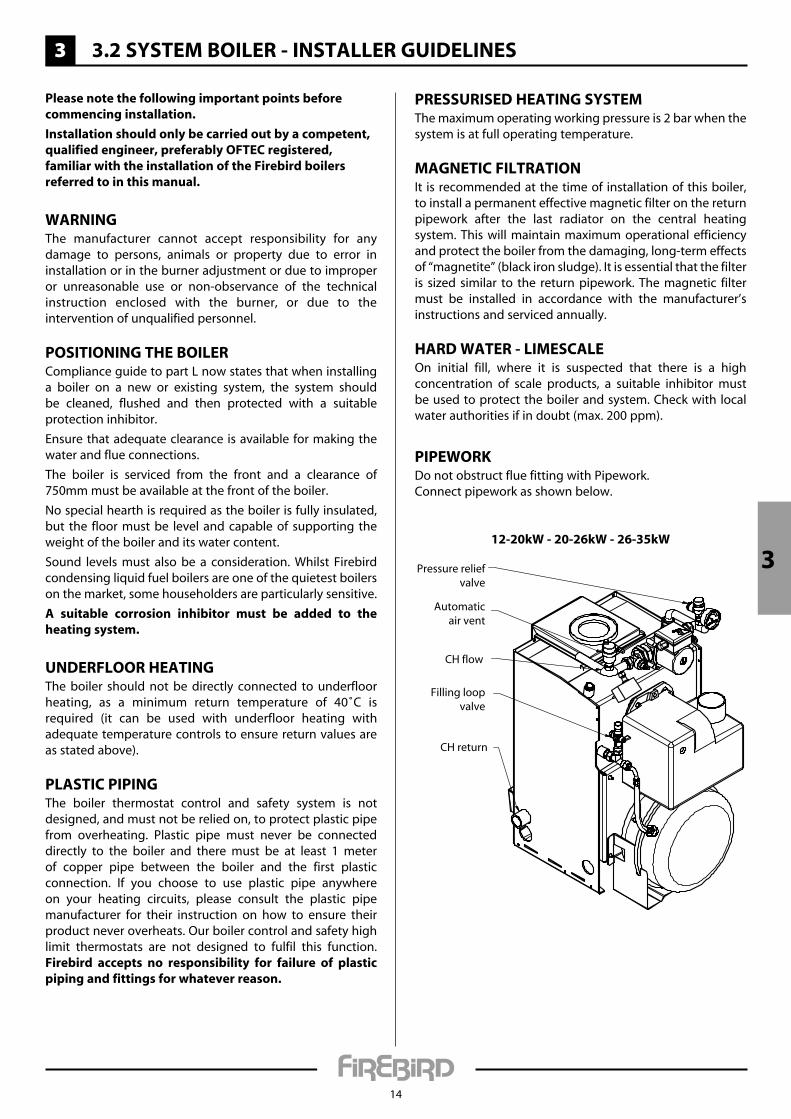
PRessuRiseD Heating systeMThe maximum operating working pressure is 2 bar when the system is at full operating temperature.
MagnetiC FiltRationIt is recommended at the time of installation of this boiler, to install a permanent effective magnetic filter on the return pipework after the last radiator on the central heating system. This will maintain maximum operational efficiency and protect the boiler from the damaging, long-term effects of “magnetite” (black iron sludge). It is essential that the filter is sized similar to the return pipework. The magnetic filter must be installed in accordance with the manufacturer’s instructions and serviced annually.
HaRD WateR - liMesCaleOn initial fill, where it is suspected that there is a high concentration of scale products, a suitable inhibitor must be used to protect the boiler and system. Check with local water authorities if in doubt (max. 200 ppm).
PiPeWoRKDo not obstruct flue fitting with Pipework.Connect pipework as shown below.
12-20kW - 20-26kW - 26-35kW
Automaticair vent
Pressure reliefvalve
CH flow
CH return
Filling loopvalve
3
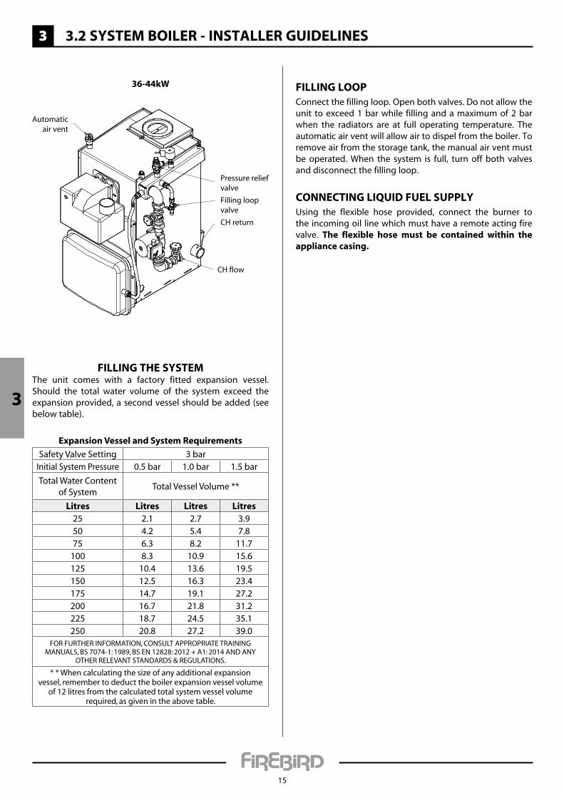
36-44kW
Automaticair vent
Pressure reliefvalve
CH flow
CH return
Filling loopvalve
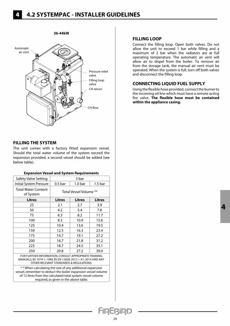
Filling tHe systeMThe unit comes with a factory fitted expansion vessel. Should the total water volume of the system exceed the expansion provided, a second vessel should be added (see below table).
expansion vessel and system Requirements
Safety Valve Setting 3 barInitial System Pressure 0.5 bar 1.0 bar 1.5 bar
Total Water Content of System
Total Vessel Volume **
litres litres litres litres25 2.1 2.7 3.950 4.2 5.4 7.875 6.3 8.2 11.7
100 8.3 10.9 15.6125 10.4 13.6 19.5150 12.5 16.3 23.4175 14.7 19.1 27.2200 16.7 21.8 31.2225 18.7 24.5 35.1250 20.8 27.2 39.0
FOR FURTHER INFORMATION, CONSULT APPROPRIATE TRAININg MANUALS, BS 7074-1: 1989, BS EN 12828: 2012 + A1: 2014 AND ANy
OTHERRELEVANTSTANDARDS®ULATIONS.
* * When calculating the size of any additional expansion vessel, remember to deduct the boiler expansion vessel volume
of 12 litres from the calculated total system vessel volume required, as given in the above table.
3 3.2 systeM BoileR - installeR guiDelines
Filling looPConnect the filling loop. Open both valves. Do not allow the unit to exceed 1 bar while filling and a maximum of 2 bar when the radiators are at full operating temperature. The automatic air vent will allow air to dispel from the boiler. To remove air from the storage tank, the manual air vent must be operated. When the system is full, turn off both valves and disconnect the filling loop.
ConneCting liQuiD Fuel suPPlyUsing the flexible hose provided, connect the burner to the incoming oil line which must have a remote acting fire valve. the flexible hose must be contained within the appliance casing.
15
3

3 3.2 systeM BoileR - installeR guiDelines
16
Correct position of flap valve
"TOP" mark
Jubilee clip
Jubilee clip
Flap valve
Balanced flue
"TOP" mark
Snorkel
1. Push the flap valve into the balanced flue air intake.
2. Ensure that the flap valve is in the correct position.
3. Push the snorkel hose over the flap valve and air intake and secure with a jubilee clip.
4. Attach the other end of the snorkel hose to the burner with jubilee clip.
FlaP valve installation
3
3 3.2 systeM BoileR - installeR guiDelines
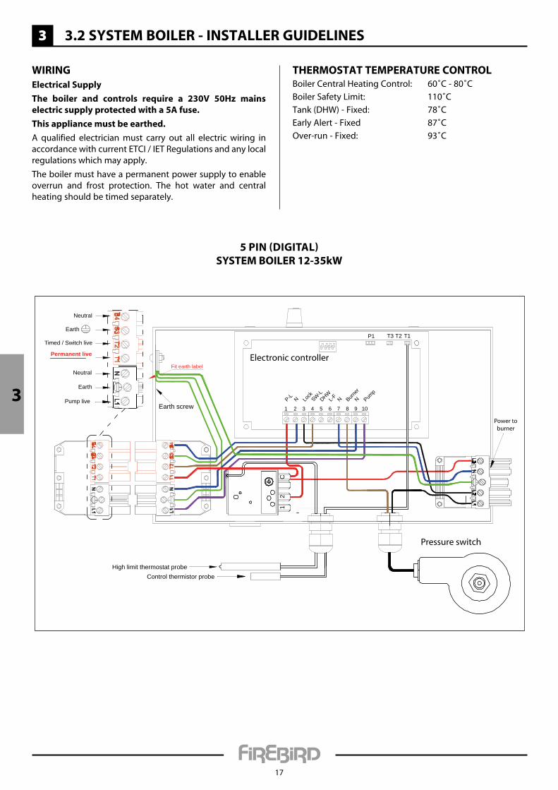
Pump live
Earth
Neutral
Permanent live
Timed / Switch live
Neutral
Earth
Earth screw
Power toburner
High limit thermostat probeControl thermistor probe
1 2 3 4 5 6 7 8 9 10Pum
pNBurner
NL-FDHWSW-L
Lock
NP-L
T1T2T3P1
C2
1
Fit earth labelElectronic controller
Pressure switch
17
5 PIN (DIgITAL)SySTEM BOILER 12-35kW
3
WiRingelectrical supply
the boiler and controls require a 230v 50Hz mains electric supply protected with a 5a fuse.
this appliance must be earthed.
A qualified electrician must carry out all electric wiring in accordance with current ETCI / IET Regulations and any local regulations which may apply.
The boiler must have a permanent power supply to enable overrun and frost protection. The hot water and central heating should be timed separately.
tHeRMostat teMPeRatuRe ContRolBoiler Central Heating Control: 60˚C - 80˚C
Boiler Safety Limit: 110˚C
Tank (DHW) - Fixed: 78˚C
Early Alert - Fixed 87˚C
Over-run - Fixed: 93˚C
3 3.2 systeM BoileR - installeR guiDelines
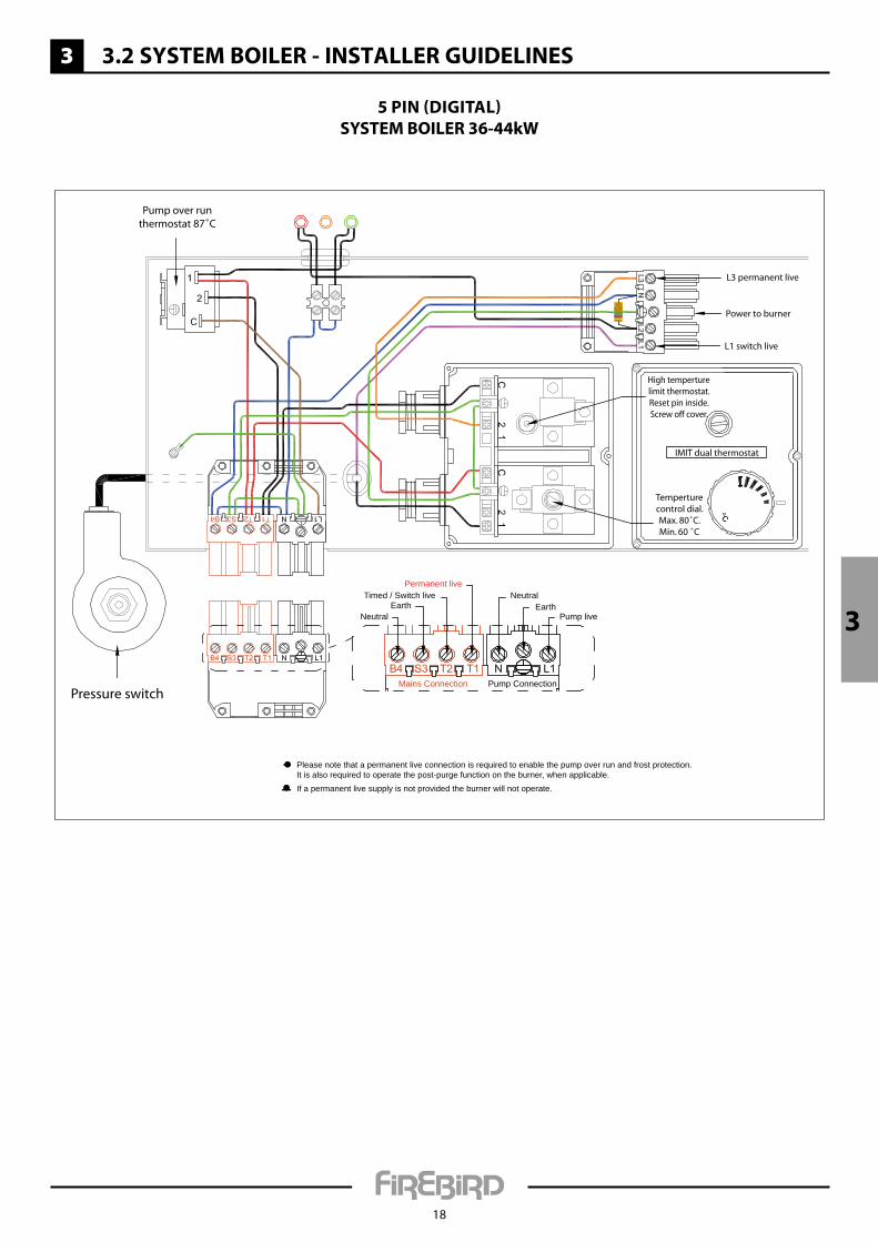
Power to burner
Pressure switch
High temperturelimit thermostat.Reset pin inside.Screw off cover.
Temperturecontrol dial.Max. 80˚C.Min. 60 ˚C
IMIT dual thermostat
Pump over runthermostat 87˚C
Pump liveEarth
NeutralPermanent live
Timed / Switch live
NeutralEarth
L1 switch live
Please note that a permanent live connection is required to enable the pump over run and frost protection.It is also required to operate the post-purge function on the burner, when applicable.If a permanent live supply is not provided the burner will not operate.
Mains Connection Pump Connection
L3 permanent live
18
5 PIN (DIgITAL)SySTEM BOILER 36-44kW
3
3 3.3 systeM BoileR - teCHniCal Details
19
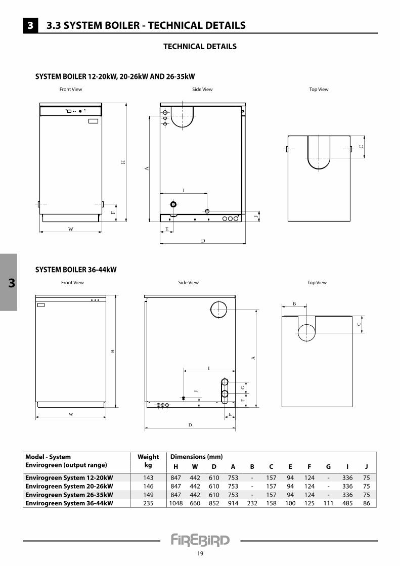
teCHniCal Details
Model - systemenvirogreen (output range)
Weightkg
Dimensions (mm)
H W D a B C e F g i J
envirogreen system 12-20kW 143 847 442 610 753 - 157 94 124 - 336 75envirogreen system 20-26kW 146 847 442 610 753 - 157 94 124 - 336 75envirogreen system 26-35kW 149 847 442 610 753 - 157 94 124 - 336 75envirogreen system 36-44kW 235 1048 660 852 914 232 158 100 125 111 485 86
F
E
J
I
H
D
W
A
C
Front View Side View Top View
H
W
A
I
J
C
FG
E
B
D
Front View Side View Top View
SySTEM BOILER 12-20kW, 20-26kW AND 26-35kW
SySTEM BOILER 36-44kW
3

3
3 3.3 systeM BoileR - teCHniCal Details
20
Only for 36-44 kW3
18 24 5 4
1213 14
3 1 2 11 9 8
15 19 2010
17
21
22
23
6
7
16
19
For burner parts refer to burner manual
No. Qty Description 12-20 kW 20-26 kW 26-35 kW 36-44 kW
1 4 Tube baffle BA110907 BA110907 BA110907 BA111503 (qty 6)
2 5 Tube baffle single BA110908 BA110908 BA110908 BA111502 (qty 8)
3 4 Smoke baffle BA212022 BA212028 BA212122 BA211651 (qty 8)
4 1 Door seal ACC035GRA ACC035GRA ACC035GRA ACC044GRA
5 1 Door duroboard ACC035GSK ACC035GSK ACC035GSK ACC044GSK
6 1 Flue gasket ACC000FRG ACC000FRG ACC000FRG ACC044FRG
7 1 Stat pocket ACC003PKT ACC003PKT ACC003PKT ACC003PKT
8 1 Condensate trap ACC000TRP ACC000TRP ACC000TRP ACC000TRP
9 1 Condensate hose ACC000FLX ACC000FLX ACC000FLX ACC000FLX
10 1 Drain cock ACC012DRC ACC012DRC ACC012DRC ACC012DRC
11 1 Heat deflector ACC000HTD ACC000HTD ACC000HTD ACC044HTD
12 1 Air hose ACC000SSH ACC000SSH ACC000SSH ACC000LSH
13 1 Flap valve ACC000FLP ACC000FLP ACC000FLP -
14 1 Control panel ACP001CSB ACP001CSB ACP001CSB ACP001CK3
15 1 Casing right side ACP002CSR ACP002CSR ACP002CSR ACP011CSR
16 1 Casing left side ACP013CSL ACP013CSL ACP013CSL ACP012CSL
17 1 Casing back support ACP006CK ACP006CK ACP006CK ACP006CK3
18 1 Casing front ACP004CKI ACP004CKI ACP004CKI ACP004CK3
19 2 Side flue blank ACP007CCE ACP007CCE ACP007CCE -
20 1 Side half moon blank ACP008CCE ACP008CCE ACP008CCE -
21 1 Casing top ACP005CKI ACP005CKI ACP005CKI ACP005CK3
22 1 Top flue blank ACP009CKI ACP009CKI ACP009CKI ACP009CK3
23 1 Top half moon blank ACP010CKI ACP010CKI ACP010CKI ACP010CK3
24 1 Pressure vessel ACC012PVL ACC012PVL ACC012PVL ACC018PVL
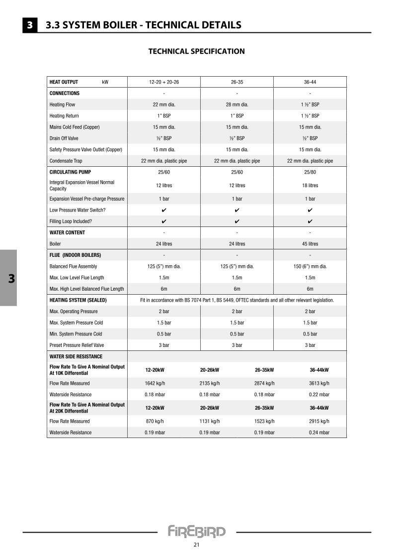
Water Side reSiStance
Flow rate to Give a nominal Output at 10K differential
12-20kW 20-26kW 26-35kW 36-44kW
Flow Rate Measured 1642 kg/h 2135 kg/h 2874 kg/h 3613 kg/h
Waterside Resistance 0.18 mbar 0.18 mbar 0.18 mbar 0.22 mbar
Flow rate to Give a nominal Output at 20K differential
12-20kW 20-26kW 26-35kW 36-44kW
Flow Rate Measured 870 kg/h 1131 kg/h 1523 kg/h 2915 kg/h
Waterside Resistance 0.19 mbar 0.19 mbar 0.19 mbar 0.24 mbar
Heat Output kW 12-20 + 20-26 26-35 36-44
cOnnectiOnS - - -
Heating Flow 22 mm dia. 28 mm dia. 1 ½” BSP
Heating Return 1” BSP 1” BSP 1 ½” BSP
Mains Cold Feed (Copper) 15 mm dia. 15 mm dia. 15 mm dia.
Drain Off Valve ½” BSP ½” BSP ½” BSP
Safety Pressure Valve Outlet (Copper) 15 mm dia. 15 mm dia. 15 mm dia.
Condensate Trap 22 mm dia. plastic pipe 22 mm dia. plastic pipe 22 mm dia. plastic pipe
circulatinG pump 25/60 25/60 25/80
Integral Expansion Vessel Normal Capacity
12 litres 12 litres 18 litres
Expansion Vessel Pre-charge Pressure 1 bar 1 bar 1 bar
Low Pressure Water Switch? ✔ ✔ ✔
Filling Loop Included? ✔ ✔ ✔
Water cOntent - - -
Boiler 24 litres 24 litres 45 litres
Flue (indOOr BOilerS) - - -
Balanced Flue Assembly 125 (5”) mm dia. 125 (5”) mm dia. 150 (6”) mm dia.
Max. Low Level Flue Length 1.5m 1.5m 1.5m
Max. High Level Balanced Flue Length 6m 6m 6m
HeatinG SyStem (Sealed) Fit in accordance with BS 7074 Part 1, BS 5449, OFTEC standards and all other relevant legislation.
Max. Operating Pressure 2 bar 2 bar 2 bar
Max. System Pressure Cold 1.5 bar 1.5 bar 1.5 bar
Min. System Pressure Cold 0.5 bar 0.5 bar 0.5 bar
Preset Pressure Relief Valve 3 bar 3 bar 3 bar
3 3.3 systeM BoileR - teCHniCal Details
21
teCHniCal sPeCiFiCation
3
4
22
4.1 systeMPaC - HouseHolDeR/enD useR inFoRMation
BoileR tHeRMostat/tHeRMistoR FunCtionThe control thermostat on the boiler allows the householder to vary temperature to central heating from a low of 60˚C to 80˚C, depending on the model. Thermostats have a tolerance of ± 4˚C.
In accordance with EU boiler standards, your boiler is also fitted with a safety high limit thermostat, fixed at 110˚C. This system protects the boiler in the event of the control thermostat failing and keeps the boiler safe.
The safety high limit thermostat will shut the boiler off and will require the limit button to be pushed to restart the boiler. It is recommended to call a service engineer to establish the cause.
BuRneR loCKoutThe boiler is factory fitted with a burner control box lockout safety feature which operates automatically if a fault occurs in the burner operation. Should this occur, the light on the front of the burner will illuminate.
Press the reset button a maximum of two times. If the boiler fails to light, call a service engineer who should check the following:
a. An interruption in the fuel supply (eg. empty fuel supply tank).B. An electrical supply fault.C. A fault with the burner or its safety control system.D. The failure of a burner component.e. Worn or dirty fuel nozzle.F. Incorrect flue installation.
Before attempting to restart the boiler, the front panel and the burner cover should be removed and a visual check made for any obvious problems such as oil leaks, loose connections etc. This should be done by a service engineer.
Please consult with your installer regarding the operation of your boiler. this should include timer operation/room thermostat operation and any other additional operational features.
the basic features of the control panel are outlined below.
Minimum MaximumMedium
4
4
23
4.2 systeMPaC - installeR guiDelines
Please note the following important points before commencing installation.
installation should only be carried out by a competent, qualified engineer, preferably oFteC registered, familiar with the installation of the Firebird boilers referred to in this manual.
WaRningThe manufacturer cannot accept responsibility for any damage to persons, animals or property due to error in installation or in the burner adjustment or due to improper or unreasonable use or non-observance of the technical instruction enclosed with the burner, or due to the intervention of unqualified personnel.
Positioning tHe BoileRCompliance guide to part L now states that when installing a boiler on a new or existing system, the system should be cleaned, flushed and then protected with a suitable protection inhibitor.
Ensure that adequate clearance is available for making the water and flue connections.
The boiler is serviced from the front and a clearance of 750mm must be available at the front of the boiler.
No special hearth is required as the boiler is fully insulated, but the floor must be level and capable of supporting the weight of the boiler and its water content.
Sound levels must also be a consideration. Whilst Firebird condensing liquid fuel boilers are one of the quietest boilers on the market, some householders are particularly sensitive.
a suitable corrosion inhibitor must be added to the heating system.
unDeRFlooR HeatingThe boiler should not be directly connected to underfloor heating, as a minimum return temperature of 40˚C is required (it can be used with underfloor heating with adequate temperature controls to ensure return values are as stated above).
PlastiC PiPingThe boiler thermostat control and safety system is not designed, and must not be relied on, to protect plastic pipe from overheating. Plastic pipe must never be connected directly to the boiler and there must be at least 1 meter of copper pipe between the boiler and the first plastic connection. If you choose to use plastic pipe anywhere on your heating circuits, please consult the plastic pipe manufacturer for their instruction on how to ensure their product never overheats. Our boiler control and safety high limit thermostats are not designed to fulfil this function. Firebird accepts no responsibility for failure of plastic piping and fittings for whatever reason.
PRessuRiseD Heating systeMThe maximum operating working pressure is 2 bar when the system is at full operating temperature.
MagnetiC FiltRationIt is recommended at the time of installation of this boiler, to install a permanent effective magnetic filter on the return pipework after the last radiator on the central heating system. This will maintain maximum operational efficiency and protect the boiler from the damaging, long-term effects of “magnetite” (black iron sludge). It is essential that the filter is sized similar to the return pipework. The magnetic filter must be installed in accordance with the manufacturer’s instructions and serviced annually.
HaRD WateR - liMesCaleOn initial fill, where it is suspected that there is a high concentration of scale products, a suitable inhibitor must be used to protect the boiler and system. Check with local water authorities if in doubt (max. 200 ppm).
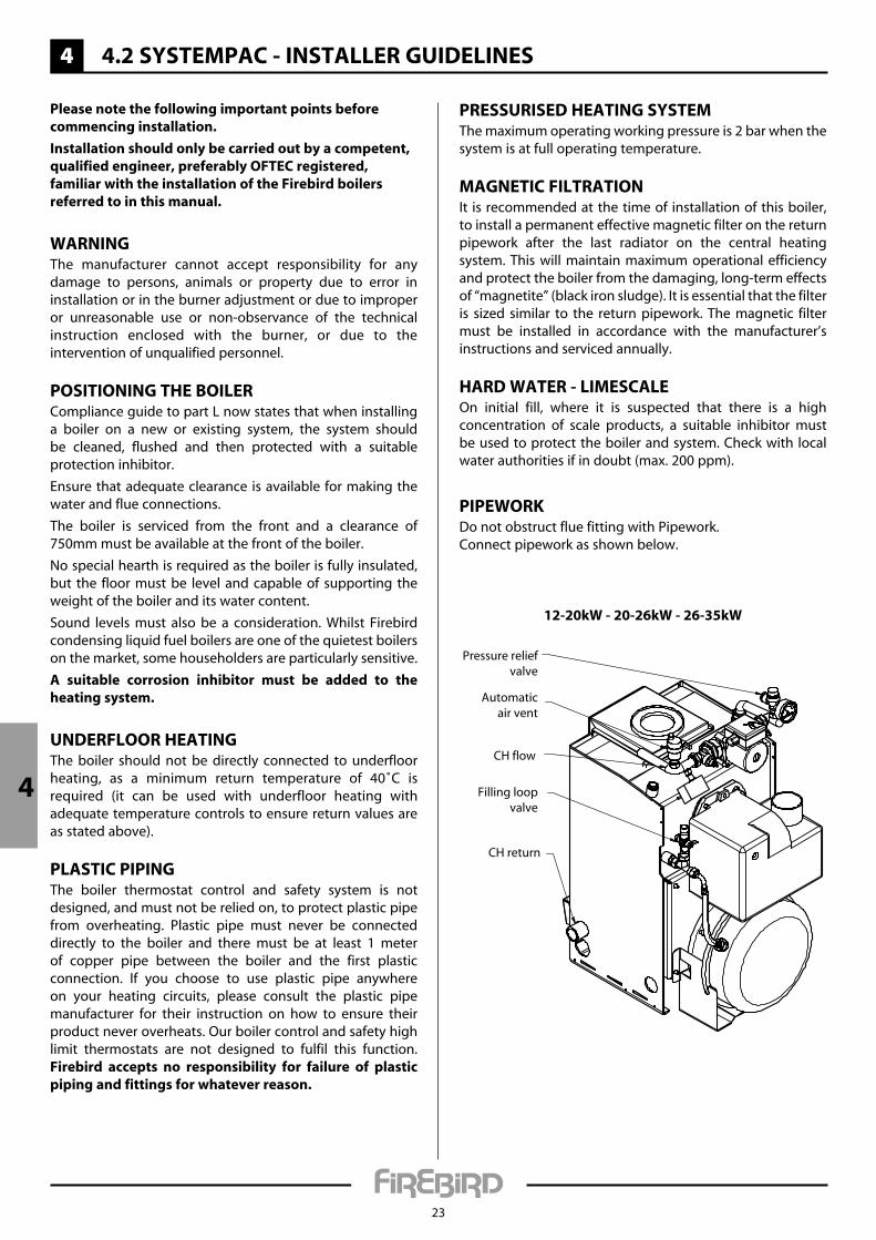
PiPeWoRKDo not obstruct flue fitting with Pipework.Connect pipework as shown below.
12-20kW - 20-26kW - 26-35kW
Automaticair vent
Pressure reliefvalve
CH flow
CH return
Filling loopvalve
4
4
36-44kW
Automaticair vent
Pressure reliefvalve
CH flow
CH return
Filling loopvalve
Filling tHe systeMThe unit comes with a factory fitted expansion vessel. Should the total water volume of the system exceed the expansion provided, a second vessel should be added (see below table).
expansion vessel and system Requirements
Safety Valve Setting 3 barInitial System Pressure 0.5 bar 1.0 bar 1.5 bar
Total Water Content of System
Total Vessel Volume **
litres litres litres litres25 2.1 2.7 3.950 4.2 5.4 7.875 6.3 8.2 11.7
100 8.3 10.9 15.6125 10.4 13.6 19.5150 12.5 16.3 23.4175 14.7 19.1 27.2200 16.7 21.8 31.2225 18.7 24.5 35.1250 20.8 27.2 39.0
FOR FURTHER INFORMATION, CONSULT APPROPRIATE TRAININg MANUALS, BS 7074-1: 1989, BS EN 12828: 2012 + A1: 2014 AND ANy
OTHERRELEVANTSTANDARDS®ULATIONS.
* * When calculating the size of any additional expansion vessel, remember to deduct the boiler expansion vessel volume
of 12 litres from the calculated total system vessel volume required, as given in the above table.
4 4.2 systeMPaC - installeR guiDelines
24
Filling looPConnect the filling loop. Open both valves. Do not allow the unit to exceed 1 bar while filling and a maximum of 2 bar when the radiators are at full operating temperature. The automatic air vent will allow air to dispel from the boiler. To remove air from the storage tank, the manual air vent must be operated. When the system is full, turn off both valves and disconnect the filling loop.
ConneCting liQuiD Fuel suPPlyUsing the flexible hose provided, connect the burner to the incoming oil line which must have a remote acting fire valve. the flexible hose must be contained within the appliance casing.
4 4.2 systeMPaC - installeR guiDelines
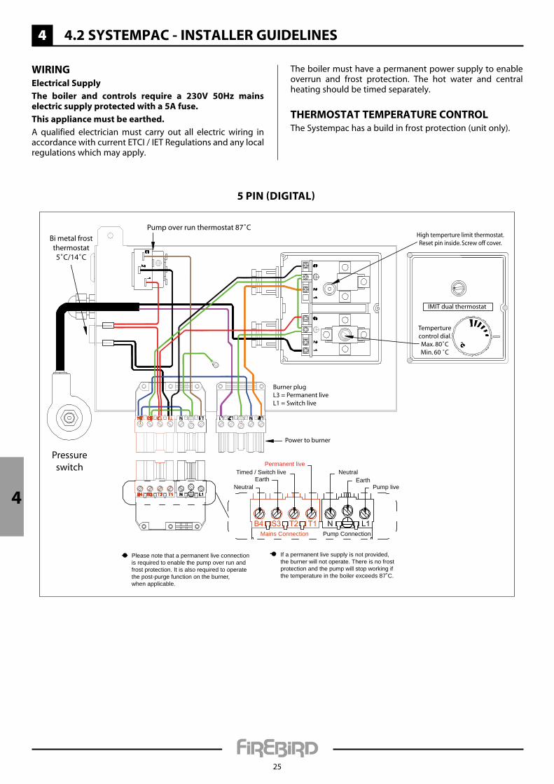
Power to burner
Pressureswitch
High temperture limit thermostat.Reset pin inside. Screw off cover.
Temperturecontrol dial.Max. 80˚CMin. 60 ˚C
IMIT dual thermostat
Pump over run thermostat 87˚C
Pump liveEarth
NeutralPermanent live
Timed / Switch live
NeutralEarth
Burner plugL3 = Permanent liveL1 = Switch live
Please note that a permanent live connectionis required to enable the pump over run andfrost protection. It is also required to operatethe post-purge function on the burner,when applicable.
If a permanent live supply is not provided,the burner will not operate. There is no frostprotection and the pump will stop working ifthe temperature in the boiler exceeds 87˚C.
Bi metal frostthermostat5˚C/14˚C
Mains Connection Pump Connection
25
WiRingelectrical supply
the boiler and controls require a 230v 50Hz mains electric supply protected with a 5a fuse.
this appliance must be earthed.
A qualified electrician must carry out all electric wiring in accordance with current ETCI / IET Regulations and any local regulations which may apply.
The boiler must have a permanent power supply to enable overrun and frost protection. The hot water and central heating should be timed separately.
tHeRMostat teMPeRatuRe ContRolThe Systempac has a build in frost protection (unit only).
4
5 PIN (DIgITAL)

4
4 4.2 systeMPaC - installeR guiDelines
26
Correct position of flap valve
"TOP" mark
Jubilee clip
Jubilee clip
Flap valve
Balanced flue
"TOP" mark
Snorkel
1. Push the flap valve into the balanced flue air intake.
2. Ensure that the flap valve is in the correct position.
3. Push the snorkel hose over the flap valve and air intake and secure with a jubilee clip.
4. Attach the other end of the snorkel hose to the burner with jubilee clip.
Flue installation
4 4.3 systeMPaC - teCHniCal Details
27
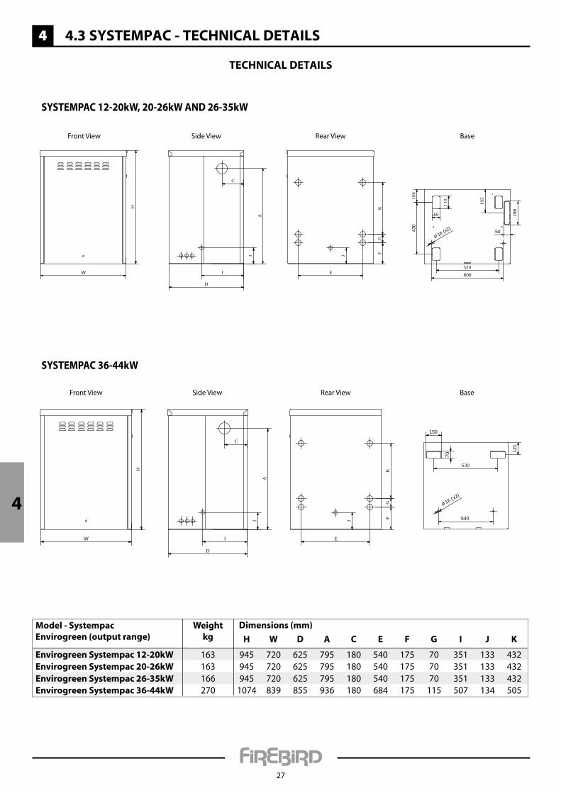
teCHniCal Details
Model - systempacenvirogreen (output range)
Weightkg
Dimensions (mm)
H W D a C e F g i J K
envirogreen systempac 12-20kW 163 945 720 625 795 180 540 175 70 351 133 432envirogreen systempac 20-26kW 163 945 720 625 795 180 540 175 70 351 133 432envirogreen systempac 26-35kW 166 945 720 625 795 180 540 175 70 351 133 432envirogreen systempac 36-44kW 270 1074 839 855 936 180 684 175 115 507 134 505
W
H
Ø 16 (x2)
600
196
430
50
195
110
66
108
520
Front View
J
E
FG
K
Rear View
A
J
I
C
D
Side View Base
W
H
Ø 16 (x2)
150
70
121
540
630
Front View
J
E
FG
KRear View
A
J
I
C
D
Side View Base
SySTEMPAC 12-20kW, 20-26kW AND 26-35kW
SySTEMPAC 36-44kW
4
4
4 4.3 systeMPaC - teCHniCal Details
28
Only for 36-44 kW
3
19 24 5 3 12 89
11
10
1213
4
221815
16 1714 20
7 6
2123
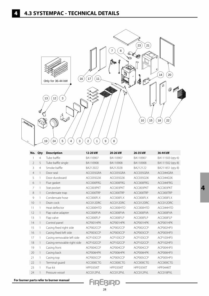
No. Qty Description 12-20 kW 20-26 kW 26-35 kW 36-44 kW
1 4 Tube baffle BA110907 BA110907 BA110907 BA111503 (qty 6)
2 5 Tube baffle single BA110908 BA110908 BA110908 BA111502 (qty 8)
3 4 Smoke baffle BA212022 BA212028 BA212122 BA211651 (qty 8)
4 1 Door seal ACC035GRA ACC035GRA ACC035GRA ACC044GRA
5 1 Door duroboard ACC035GSK ACC035GSK ACC035GSK ACC044GSK
6 1 Flue gasket ACC000FRG ACC000FRG ACC000FRG ACC044FRG
7 1 Stat pocket ACC003PKT ACC003PKT ACC003PKT ACC003PKT
8 1 Condensate trap ACC000TRP ACC000TRP ACC000TRP ACC000TRP
9 1 Condensate hose ACC000FLX ACC000FLX ACC000FLX ACC000FLX
10 1 Drain cock ACC012DRC ACC012DRC ACC012DRC ACC012DRC
11 1 Heat deflector ACC000HTD ACC000HTD ACC000HTD ACC044HTD
12 1 Flap valve adapter ACC000FVA ACC000FVA ACC000FVA ACC000FVA
13 1 Flap valve ACC000FLP ACC000FLP ACC000FLP ACC000FLP
14 1 Control panel ACP001HPK ACP001HPK ACP001HPK ACP001HPK
15 1 Casing fixed right side ACP002CCP ACP002CCP ACP002CCP ACP002HP3
16 1 Casing fixed left side ACP003CCP ACP003CCP ACP003CCP ACP003HP3
17 1 Casing removable left side ACP103CCP ACP103CCP ACP103CCP ACP103HP3
18 1 Casing removable right side ACP102CCP ACP102CCP ACP102CCP ACP102HP3
19 1 Casing front ACP004CCP ACP004CCP ACP004CCP ACP004HP3
20 1 Casing back ACP006HPK ACP006HPK ACP006HPK ACP006HP3
21 1 Casing top ACP005CCP ACP005CCP ACP005CCP ACP005HP3
22 1 Terminal guard ACC000CTG ACC000CTG ACC000CTG ACC000CTG
23 1 Flue kit HPF035KIT HPF035KIT HPF035KIT HPF044KIT
24 1 Pressure vessel ACC012PVL ACC012PVL ACC012PVL ACC018PVL
For burner parts refer to burner manual
4 4.3 systeMPaC - teCHniCal Details
29
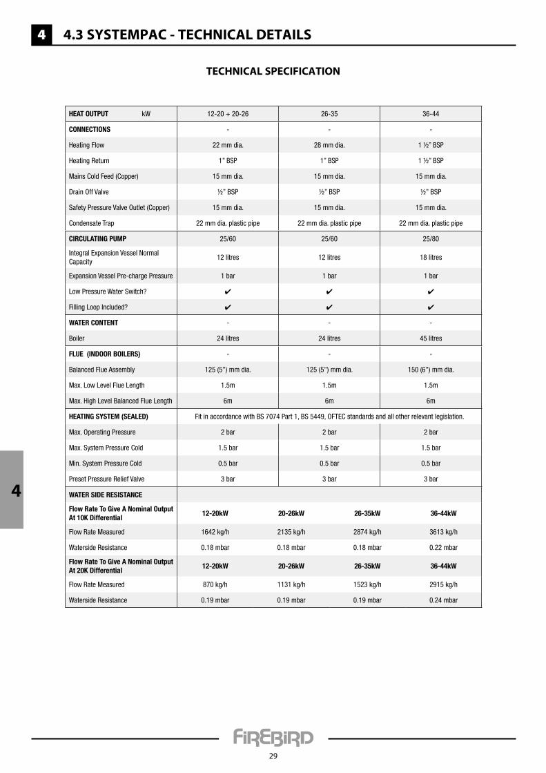
teCHniCal sPeCiFiCation
Heat Output kW 12-20 + 20-26 26-35 36-44
cOnnectiOnS - - -
Heating Flow 22 mm dia. 28 mm dia. 1 ½” BSP
Heating Return 1” BSP 1” BSP 1 ½” BSP
Mains Cold Feed (Copper) 15 mm dia. 15 mm dia. 15 mm dia.
Drain Off Valve ½” BSP ½” BSP ½” BSP
Safety Pressure Valve Outlet (Copper) 15 mm dia. 15 mm dia. 15 mm dia.
Condensate Trap 22 mm dia. plastic pipe 22 mm dia. plastic pipe 22 mm dia. plastic pipe
circulatinG pump 25/60 25/60 25/80
Integral Expansion Vessel Normal Capacity
12 litres 12 litres 18 litres
Expansion Vessel Pre-charge Pressure 1 bar 1 bar 1 bar
Low Pressure Water Switch? ✔ ✔ ✔
Filling Loop Included? ✔ ✔ ✔
Water cOntent - - -
Boiler 24 litres 24 litres 45 litres
Flue (indOOr BOilerS) - - -
Balanced Flue Assembly 125 (5”) mm dia. 125 (5”) mm dia. 150 (6”) mm dia.
Max. Low Level Flue Length 1.5m 1.5m 1.5m
Max. High Level Balanced Flue Length 6m 6m 6m
HeatinG SyStem (Sealed) Fit in accordance with BS 7074 Part 1, BS 5449, OFTEC standards and all other relevant legislation.
Max. Operating Pressure 2 bar 2 bar 2 bar
Max. System Pressure Cold 1.5 bar 1.5 bar 1.5 bar
Min. System Pressure Cold 0.5 bar 0.5 bar 0.5 bar
Preset Pressure Relief Valve 3 bar 3 bar 3 bar
4 Water Side reSiStance
Flow rate to Give a nominal Output at 10K differential
12-20kW 20-26kW 26-35kW 36-44kW
Flow Rate Measured 1642 kg/h 2135 kg/h 2874 kg/h 3613 kg/h
Waterside Resistance 0.18 mbar 0.18 mbar 0.18 mbar 0.22 mbar
Flow rate to Give a nominal Output at 20K differential
12-20kW 20-26kW 26-35kW 36-44kW
Flow Rate Measured 870 kg/h 1131 kg/h 1523 kg/h 2915 kg/h
Waterside Resistance 0.19 mbar 0.19 mbar 0.19 mbar 0.24 mbar

5
30
5.1 sliMline systeMPaC - HouseHolDeR/enD useR inFoRMation
BoileR tHeRMostat/tHeRMistoR FunCtionThe control thermostat on the boiler allows the householder to vary temperature to central heating from a low of 60˚C to 80˚C, depending on the model. Thermostats have a tolerance of ± 4˚C.
In accordance with EU boiler standards, your boiler is also fitted with a safety high limit thermostat, fixed at 110˚C. This system protects the boiler in the event of the control thermostat failing and keeps the boiler safe.
The safety high limit thermostat will shut the boiler off and will require the limit button to be pushed to restart the boiler. It is recommended to call a service engineer to establish the cause.
BuRneR loCKoutThe boiler is factory fitted with a burner control box lockout safety feature which operates automatically if a fault occurs in the burner operation. Should this occur, the light on the front of the burner will illuminate.
Press the reset button a maximum of two times. If the boiler fails to light, call a service engineer who should check the following:
a. An interruption in the fuel supply (eg. empty fuel supply tank).B. An electrical supply fault.C. A fault with the burner or its safety control system.D. The failure of a burner component.e. Worn or dirty fuel nozzle.F. Incorrect flue installation.
Before attempting to restart the boiler, the front panel and the burner cover should be removed and a visual check made for any obvious problems such as oil leaks, loose connections etc. This should be done by a service engineer.
Please consult with your installer regarding the operation of your boiler. this should include timer operation/room thermostat operation and any other additional operational features.
the basic features of the control panel are outlined below.
Minimum MaximumMedium
5

5
31
5.2 sliMline systeMPaC - installeR guiDelines
Please note the following important points before commencing installation.
installation should only be carried out by a competent, qualified engineer, preferably oFteC registered, familiar with the installation of the Firebird boilers referred to in this manual.
WaRningThe manufacturer cannot accept responsibility for any damage to persons, animals or property due to error in installation or in the burner adjustment or due to improper or unreasonable use or non-observance of the technical instruction enclosed with the burner, or due to the intervention of unqualified personnel.
Positioning tHe BoileRCompliance guide to part L now states that when installing a boiler on a new or existing system, the system should be cleaned, flushed and then protected with a suitable protection inhibitor.
Ensure that adequate clearance is available for making the water and flue connections.
The boiler is serviced from the front and a clearance of 750mm must be available at the front of the boiler.
No special hearth is required as the boiler is fully insulated, but the floor must be level and capable of supporting the weight of the boiler and its water content.
Sound levels must also be a consideration. Whilst Firebird condensing liquid fuel boilers are one of the quietest boilers on the market, some householders are particularly sensitive.
a suitable corrosion inhibitor must be added to the heating system.
unDeRFlooR HeatingThe boiler should not be directly connected to underfloor heating, as a minimum return temperature of 40˚C is required (it can be used with underfloor heating with adequate temperature controls to ensure return values are as stated above).
PlastiC PiPingThe boiler thermostat control and safety system is not designed, and must not be relied on, to protect plastic pipe from overheating. Plastic pipe must never be connected directly to the boiler and there must be at least 1 meter of copper pipe between the boiler and the first plastic connection. If you choose to use plastic pipe anywhere on your heating circuits, please consult the plastic pipe manufacturer for their instruction on how to ensure their product never overheats. Our boiler control and safety high limit thermostats are not designed to fulfil this function. Firebird accepts no responsibility for failure of plastic piping and fittings for whatever reason.
PRessuRiseD Heating systeMThe maximum operating working pressure is 2 bar when the system is at full operating temperature.
MagnetiC FiltRationIt is recommended at the time of installation of this boiler, to install a permanent effective magnetic filter on the return pipework after the last radiator on the central heating system. This will maintain maximum operational efficiency
and protect the boiler from the damaging, long-term effects of “magnetite” (black iron sludge). It is essential that the filter is sized similar to the return pipework. The magnetic filter must be installed in accordance with the manufacturer’s instructions and serviced annually.
HaRD WateR - liMesCaleOn initial fill, where it is suspected that there is a high concentration of scale products, a suitable inhibitor must be used to protect the boiler and system. Check with local water authorities if in doubt (max. 200 ppm).
PiPeWoRKDo not obstruct flue fitting with Pipework.Connect pipework as shown below.
Automaticair vent
Pressurereliefvalve
CH flow
CH return
Filling loopvalve
Filling tHe systeMThe unit comes with a factory fitted expansion vessel. Should the total water volume of the system exceed the expansion provided, a second vessel should be added (see below table).
expansion vessel and system Requirements
Safety Valve Setting 3 barInitial System Pressure 0.5 bar 1.0 bar 1.5 bar
Total Water Content of System
Total Vessel Volume **
litres litres litres litres25 2.1 2.7 3.950 4.2 5.4 7.875 6.3 8.2 11.7
100 8.3 10.9 15.6125 10.4 13.6 19.5150 12.5 16.3 23.4175 14.7 19.1 27.2200 16.7 21.8 31.2225 18.7 24.5 35.1250 20.8 27.2 39.0
FOR FURTHER INFORMATION, CONSULT APPROPRIATE TRAININg MANUALS, BS 7074-1: 1989, BS EN 12828: 2012 + A1: 2014 AND ANy
OTHERRELEVANTSTANDARDS®ULATIONS.
* * When calculating the size of any additional expansion vessel, remember to deduct the boiler expansion vessel volume
of 12 litres from the calculated total system vessel volume required, as given in the above table.
5
5
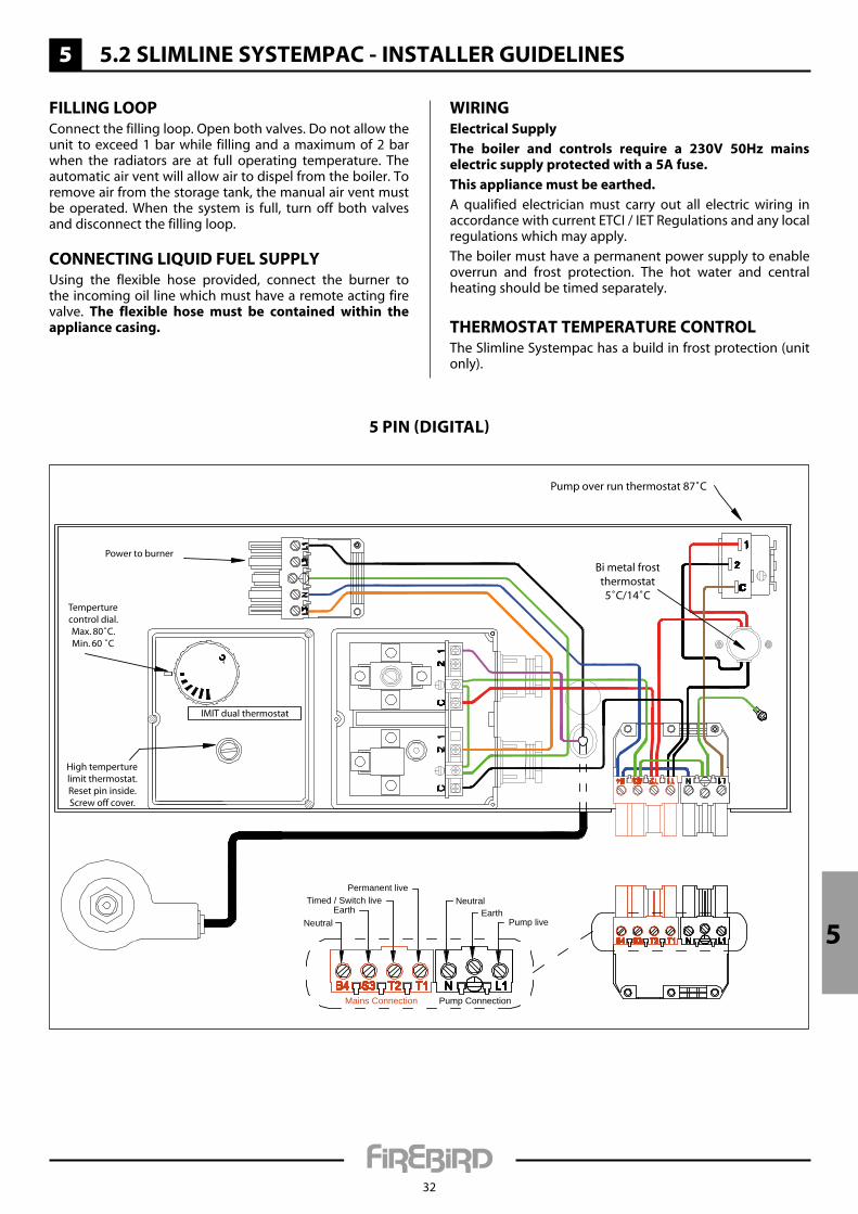
Filling looPConnect the filling loop. Open both valves. Do not allow the unit to exceed 1 bar while filling and a maximum of 2 bar when the radiators are at full operating temperature. The automatic air vent will allow air to dispel from the boiler. To remove air from the storage tank, the manual air vent must be operated. When the system is full, turn off both valves and disconnect the filling loop.
ConneCting liQuiD Fuel suPPlyUsing the flexible hose provided, connect the burner to the incoming oil line which must have a remote acting fire valve. the flexible hose must be contained within the appliance casing.
5 5.2 sliMline systeMPaC - installeR guiDelines
WiRingelectrical supply
the boiler and controls require a 230v 50Hz mains electric supply protected with a 5a fuse.
this appliance must be earthed.
A qualified electrician must carry out all electric wiring in accordance with current ETCI / IET Regulations and any local regulations which may apply.
The boiler must have a permanent power supply to enable overrun and frost protection. The hot water and central heating should be timed separately.
tHeRMostat teMPeRatuRe ContRolThe Slimline Systempac has a build in frost protection (unit only).
Bi metal frostthermostat5˚C/14˚C
Pump over run thermostat 87˚C
Power to burner
High temperturelimit thermostat.Reset pin inside.Screw off cover.
Temperturecontrol dial.Max. 80˚C.Min. 60 ˚C
IMIT dual thermostat
Pump liveEarth
NeutralPermanent live
Timed / Switch live
NeutralEarth
Mains Connection Pump Connection
32
5 PIN (DIgITAL)
5 5.2 sliMline systeMPaC - installeR guiDelines
33
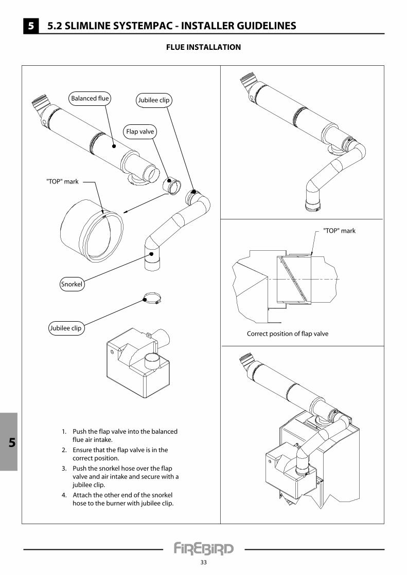
Correct position of flap valve
"TOP" mark
Jubilee clip
Jubilee clip
Flap valve
Balanced flue
"TOP" mark
Snorkel
1. Push the flap valve into the balanced flue air intake.
2. Ensure that the flap valve is in the correct position.
3. Push the snorkel hose over the flap valve and air intake and secure with a jubilee clip.
4. Attach the other end of the snorkel hose to the burner with jubilee clip.
Flue installation
5
5
5 5.3 sliMline systeMPaC - teCHniCal Details
34
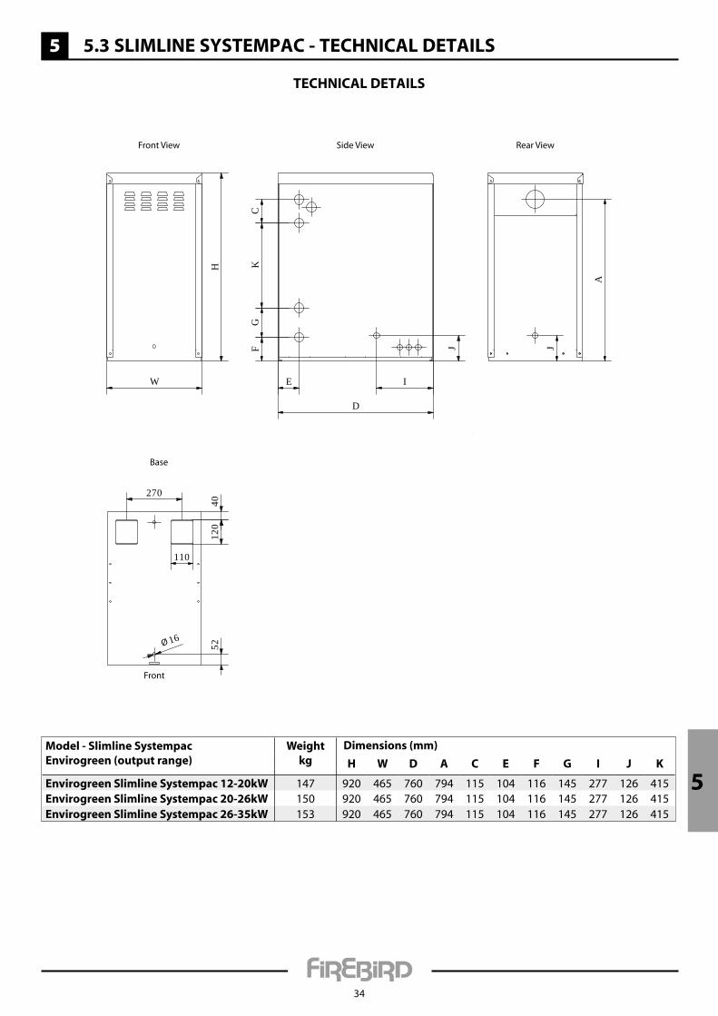
teCHniCal Details
Model - slimline systempacenvirogreen (output range)
Weightkg
Dimensions (mm)
H W D a C e F g i J K
envirogreen slimline systempac 12-20kW 147 920 465 760 794 115 104 116 145 277 126 415envirogreen slimline systempac 20-26kW 150 920 465 760 794 115 104 116 145 277 126 415envirogreen slimline systempac 26-35kW 153 920 465 760 794 115 104 116 145 277 126 415
H
W
FG
C
D
J
I
K
E
J
A
270
4012
0
110
Ø 16
52
Front View Side View Rear View
Base
Front
5 5.3 sliMline systeMPaC - teCHniCal Details
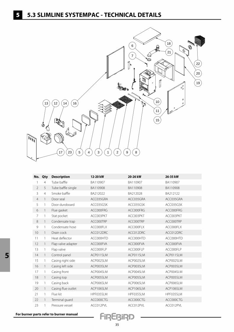
35
13 12 14
17 23 5 4 3 1 2 9 8
10
11
15
16
7
6
21
18
19
20
22
No. Qty Description 12-20 kW 20-26 kW 26-35 kW
1 4 Tube baffle BA110907 BA110907 BA110907
2 5 Tube baffle single BA110908 BA110908 BA110908
3 4 Smoke baffle BA212022 BA212028 BA212122
4 1 Door seal ACC035GRA ACC035GRA ACC035GRA
5 1 Door duroboard ACC035GSK ACC035GSK ACC035GSK
6 1 Flue gasket ACC000FRG ACC000FRG ACC000FRG
7 1 Stat pocket ACC003PKT ACC003PKT ACC003PKT
8 1 Condensate trap ACC000TRP ACC000TRP ACC000TRP
9 1 Condensate hose ACC000FLX ACC000FLX ACC000FLX
10 1 Drain cock ACC012DRC ACC012DRC ACC012DRC
11 1 Heat deflector ACC000HTD ACC000HTD ACC000HTD
12 1 Flap valve adapter ACC000FVA ACC000FVA ACC000FVA
13 1 Flap valve ACC000FLP ACC000FLP ACC000FLP
14 1 Control panel ACP011SLM ACP011SLM ACP011SLM
15 1 Casing right side ACP002SLM ACP002SLM ACP002SLM
16 1 Casing left side ACP003SLM ACP003SLM ACP003SLM
17 1 Casing front ACP004SLM ACP004SLM ACP004SLM
18 1 Casing top ACP005SLM ACP005SLM ACP005SLM
19 1 Casing back ACP006SLM ACP006SLM ACP006SLM
20 1 Casing flue outlet ACP106SLM ACP106SLM ACP106SLM
21 1 Flue kit HPF035SLM HPF035SLM HPF035SLM
22 1 Terminal guard ACC000CTG ACC000CTG ACC000CTG
23 1 Pressure vessel ACC012PVL ACC012PVL ACC012PVL
For burner parts refer to burner manual
5

5
5 5.3 sliMline systeMPaC - teCHniCal Details
36
teCHniCal sPeCiFiCation
Heat Output kW 12-35
cOnnectiOnS -
Heating Flow 22 mm dia.
Heating Return 1” BSP
Mains Cold Feed (Copper) 15 mm dia.
Drain Off Valve ½” BSP
Safety Pressure Valve Outlet (Copper) 15 mm dia.
Condensate Trap 22 mm dia. plastic pipe
circulatinG pump 25/60
Integral Expansion Vessel Normal Capacity
12 litres
Expansion Vessel Pre-charge Pressure 1 bar
Low Pressure Water Switch? ✔
Filling Loop Included? ✔
Water cOntent -
Boiler 24 litres
Flue (indOOr BOilerS) -
Balanced Flue Assembly 125 (5”) mm dia.
Max. Low Level Flue Length 1.5m
Max. High Level Balanced Flue Length 6m
HeatinG SyStem (Sealed) Fit in accordance with BS 7074 Part 1, BS 5449, OFTEC standards and all other relevant legislation.
Max. Operating Pressure 2 bar
Max. System Pressure Cold 1.5 bar
Min. System Pressure Cold 0.5 bar
Preset Pressure Relief Valve 3 bar
Water Side reSiStance
Flow rate to Give a nominal Output at 10K differential
12-20kW 20-26kW 26-35kW
Flow Rate Measured 1642 kg/h 2135 kg/h 2874 kg/h
Waterside Resistance 0.18 mbar 0.18 mbar 0.18 mbar
Flow rate to Give a nominal Output at 20K differential
12-20kW 20-26kW 26-35kW
Flow Rate Measured 870 kg/h 1131 kg/h 1523 kg/h
Waterside Resistance 0.19 mbar 0.19 mbar 0.19 mbar
6
37
CoMMissioning
CoMMissioning
u it is the responsibility of the installer to ensure that the boiler is properly commissioned when first used.
u the boiler should be commissioned by a competent, qualified engineer, preferably oFteC registered and familiar with Firebird products.
u the installation certificate and the commissioning certificate within the Boiler Passport should be completed and posted to Firebird within 28 days of installation (this can also be done online on the Firebird website). a copy should be retained by the commissioning engineer.
u the system should be checked thoroughly.
CHeCKlist FoR installing anDCoMMissioning a FiReBiRD BoileR
Pre-installation check:u Is the following documentation included with the
boiler: installation manual, boiler passport, burner manufacturer’s manual?
u Is the base on which the boiler is to be installed solid?u Allow sufficient room for future servicing of the boiler.
Where does the flue terminate:u Make sure there is no window, door or fence within 1
metre of the flue-terminal.u If the flue terminates in a corner or into an allyway,
re-circulation of the combustion gases in the air intake could occur. A plume dispersal may be required or an alternative flue arrangement might be available. Contact the Firebird technical department for advise.
u The appropriate class 1 flue must be used with a conventional flue installation. Contact Firebird if unsure.
Power supply:u Is a timed, permanent, power supply available, via a
fused spur with a 230V 50Hz mains electrical supply and a 5A fuse?
liquid fuel supply:u The burner is set for 28 Second Class C2 fuel.u A 15 micron oil filter should be placed in line with an
isolating valve prior to entry to the burner.u There must be a remote sensing fire valve.u Verify that the fuel tank has been installed correctly as
per building standards.
Boiler check:u Baffles should be checked as they may have been
disturbed during transport.u Check that the condensate trap is fitted securely,
primed with water and piped out into a suitable drain. It is easier to check the trap when the boiler door is removed.
u The boiler door should be refitted, complete with graphite seal and then tightened.
Flue check: u The flue must be fitted correctly, with a fall back to
the boiler. Note: internal fall of 2.5˚ within the flue.u For concentric balanced flue: - the cone supplied should be inserted in to the end
oftheflue; - the wall plate should be fitted with an opening forairundertheflue; - check that the flue guard is fitted. u When installing a Systempac or Slimline Systempac,
the 90˚ bend should be fitted pointing up.
Please refer to burner manual for thefollowing sections: u Boiler set-up.u Burner settings.u Flue gas analysis and fine tuning of burner.
HanDing oveR
The householder should receive:• Aclearandconcisedemonstrationoftheboiler operation and any system controls.• Thismanual,theburnermanufacturer’smanual and any other instructions.• OFTECformsCD10andCD11.• TheBoilerPassport.
The householder should be advised to:• Servicetheboilerannuallyandtoensurethatthe service records in the Boiler Passport are completed.• Readthetermsandconditionsofwarranty.• Keepallboilerdocumentationinasafeplace.
a commissioning record should be completedand a copy retained by the engineer.
this can be found in the Boiler Passport.
7
38
seRviCing
tHe BuRneR
Please refer to the burner manual for specificationand combustion check information.
ensure service is recorded in the Boiler Passport.
annual servicing must be carried out by a competent, qualified engineer, preferably oFteC registered and familiar with Firebird products.
Do not commence service until both the electrical and fuel supply to the boiler have been safely isolated.
tHe Fuel tanK
Check for oil leaks. Draw off any accumulated water and sludge from the tank by opening the drain valve. Turn off the liquid fuel supply, remove the filter bowl and wash the element clean with Kerosene.
tHe BoileR
Remove combustion access door for access to baffles and to clean heat exchanger.
Cleaning a Firebird condensing boiler:
1. Remove all baffles, including the tubular baffles in the condensing section and clean them.
2. Remove the condensate trap and clean it, place a tray under the connection for the trap. Vacuum out any loose debris from the chamber.
3. Clean the inside of the boiler with a vacuum cleaner.
4. Refit all the baffles and the condensate trap securely.
5. System pressure should not exceed 2 bar at full operating temperature. The expansion vessel should be checked during the annual service to ensure that it is operating correctly.
Check insulation sealing and the silver foil lining in combustion access door - replace if necessary. Check graphite seal and replace if necessary. When refitting this door be careful not to damage the foil and insulation by over tightening.
Check that the condensate trap is secure in position, clean and free of combustion debris. Ensure that the condensate drain is free and not blocked.
Expansion vessel pre -charge pressure should be checked annually and set according to the system design.
39
teRMs & ConDitions oF WaRRanty
Firebird products are designed and manufactured to give many years of trouble free service.
The terms laid down in the warranty must be adhered to
u Firebird provides a comprehensive, conditional warranty of 5 years on the boiler shell and 2 years on all other parts from date of installation, provided installation has occurred within 12 months from date of purchase.
u The 5 year boiler shell warranty consists of parts and labour for the first 3 years and parts only for years 4 and 5.
u The warranty will only apply if the boiler is commissioned by a competent, qualified engineer, preferably OFTEC registered and is serviced annually thereafter.
u Please ensure that the commissioning certificate within the Boiler Passport is fully completed by a competent, qualified engineer, preferably OFTEC registered and is returned to Firebird within 28 days of complete installation and commissioning. The Boiler Passport is included with every boiler and can also be completed online at the following link:
http://www.firebird.ie/index.php/boiler-passport.html.
u Correct commissioning will ensure that your boiler is set to operate at its maximum fuel efficiency.
u Consumable components, the nozzles and the oil hose are excluded.
teRMs & ConDitions oF WaRRanty
1. Warranty implies that the product shall be free from defective parts or workmanship for a period of warranty cover, which begins from the date of installation.
2. All claims under the warranty programme must be within the time limits stated on the left.
3. Installation and commissioning of the product must be in accordance with (a) instruction/technical manuals (b) all relevant standards and codes of practice.
4. A competent, qualified engineer, preferably OFTEC registered, using the correct installation and test equipment must carry out installation and commissioning.
5. This warranty does not cover special, incidental or consequential damages, injury to persons or property, or any other consequential loss.
6. Servicing of the boiler is to be carried out annually to maintain the manufacturer’s warranty.
7. Firebird accepts no liability in respect of any defect arising from incorrect installation, negligence, fair wear and tear, misuse, alteration or repair by unqualified persons.
8. Firebird will not accept any liability in respect of any defect occurring to the product due to limescale build-up and or low return water temperature.
9. The warranty programme extends to reasonable labour costs EXCEPT in the case of a 5 year warranty period whereby any valid claim made after 3 years will not include labour costs.
10. Firebird’s prior authorisation must be obtained before examination or repair of the product takes place.
11. Firebird will examine all claims made under the warranty programme and for any claims that are deemed invalid, the costs incurred will be borne by the owner.
12. The warranty programme only applies where the product was used for normal domestic heating purposes.
13. Any defective part removed under any or all of the warranty programmes MUST be returned to Firebird.
14. If this appliance is installed in a pressurised system, failure to correctly size the expansion vessel may damage the boiler and invalidate the warranty
15. A full set of warranty conditions and terms can be found on the Firebird website.
STATUTORY RIGHTS OF THE OWNER ARE NOTAFFECTED BY THIS WARRANTY
8

9
40
PRoDuCt FiCHe
ErP A Rated
ModelIdentifier
Energyefficiency
class
Rated heat outputSeasonal Efficiency
Base Model
Annual energy consumption Sound power level
kW % GJ dB
ENVIROGREEN SYSTEM
12-20kW A 20 93 50 46
20-26kW A 26 93 71 47
26-35kW A 35 92 95 52
36-44kW A 44 94 123 N/A
ENVIROGREEN SYSTEMPAC
12-20kW A 20 93 50 N/A
20-26kW A 26 93 71 N/A
26-35kW A 35 92 95 N/A
36-44kW A 44 94 123 N/A
ENVIROGREEN SlIMlINE SYSTEMPAC
12-20kW A 20 93 50 N/A
20-26kW A 26 93 71 N/A
26-35kW A 35 92 95 N/A

UK Firebird Products Ltd Phoenix House Eastern Wood Road Langage Industrial Estate Plympton Plymouth PL7 5ET
T: 01752 691177 F: 01752 691131 E: [email protected]
www.firebird.uk.com
Ireland Firebird Heating Solutions Ltd Baile Mhic Íre Co. Cork P12 HK51 Ireland
T: +353 (0)26 45253 F: +353 (0)26 45309 E: [email protected]
www.firebird.ie
This brochure was correct at the time of going to print. However, Firebird’s policy is one of continuous development. The right is reserved to change specifications, colour, and prices of the models and items illustrated and described in the publication at any time. Whilst every care has been exercised in the production of this brochure, Firebird cannot accept any liability for errors or omissions. For current details always consult Firebird Products Ltd.


![Removable Orthodontic Appliances (ROA)2 [Compatibility Mode]](https://static.fdocuments.us/doc/165x107/545eb1bfb1af9f9f638b45e3/removable-orthodontic-appliances-roa2-compatibility-mode-5584510ee0aa1.jpg)