
Installation Manual - Alamarin-JetInstallation Manual AM/288/EN/1.2.0 5 3. Attaching the mounting...
62
Installation Manual
Transcript of Installation Manual - Alamarin-JetInstallation Manual AM/288/EN/1.2.0 5 3. Attaching the mounting...

Installation Manual


Table of contentsInstallation Manual
AM/288/EN/1.2.0 iii
Table of contents1. Introduction .................................................................................................. 1
1.1. Safety precautions ............................................................................. 11.2. Symbols ............................................................................................. 1
2. General description of installation ............................................................... 33. Attaching the mounting template ................................................................ 5
3.1. Repowering installation ..................................................................... 53.1.1. Reinforced plastic mounting template .................................... 53.1.2. Aluminium mounting template .............................................. 123.1.3. Embedding the mounting template to the hull of the boat.......................................................................................................... 13
3.2. Installation out of the mould ........................................................... 133.2.1. Removable mounting template ............................................. 143.2.2. Fixed mounting template ...................................................... 16
4. Attaching the propulsion unit .................................................................... 194.1. Preparations .................................................................................... 194.2. Attaching the body .......................................................................... 204.3. Installing the lubrication system for the bearing ............................ 21
4.3.1. Front bearing ........................................................................ 214.3.2. Rear bearing ......................................................................... 23
4.4. Attaching the hydraulic cylinder ..................................................... 264.5. Attaching the hydraulic pump ......................................................... 294.6. Installing the cooling line for hydraulic cylinder oil ........................ 314.7. Attaching the grass rake ................................................................. 324.8. Installing the raw water cooling line .............................................. 33
5. Installing the control system ..................................................................... 375.1. Connecting the reversing deflector to the control system ............... 37
5.1.1. Connecting the control cables .............................................. 405.1.2. Cylinder adjustment .............................................................. 41
5.2. Connecting the steering nozzle to the control system ..................... 436. Engine installation ..................................................................................... 457. Antifouling .................................................................................................. 47Appendix 1. Grease recommendations ........................................................... 49Appendix 2. Oil recommendations ................................................................. 50Appendix 3. Tightening torques ..................................................................... 51Appendix 4. Mounting template ..................................................................... 52Appendix 5. Change in the v angle ................................................................ 53Appendix 6. Connecting rod for double installation ...................................... 54Appendix 7. Control systems ......................................................................... 55Appendix 8. Lever movement ranges ............................................................ 57

IntroductionInstallation Manual
AM/288/EN/1.2.0 1
1. IntroductionThis is the installation manual for Alamarin-Jet's Jet-288 water jet propulsionunit. This manual is intended for mechanics who install the Alamarin-Jet waterjet propulsion unit to a suitable boat.
© Alamarin-Jet Oy
Tuomisentie 16FI-62300 Härmä, FinlandTelephone: +358 10 7745 260Fax: +358 10 7745 269Internet: www.alamarinjet.com
All rights reserved.
The information in this manual may not be copied, published or reproducedin any way whatsoever or exploited for commercial purposes without explicitwritten permission from Alamarin-Jet Oy.
The information in this manual is subject to change without notice. Alamarin-Jet Oy reserves the right to modify the contents without notice.
1.1. Safety precautionsRead these instructions carefully before carrying out any procedures. Alwaysfollow these instructions and the safety precautions below.
• Only a person with adequate training is allowed to carry out the proceduresdescribed in this manual.
• The person carrying out the procedures must always be wearing appropriateprotective equipment.
• The work premises must be sufficiently large, safe and well-lit.
• The tools used must be clean and appropriate for the purpose.
1.2. SymbolsPlease refer to table 1 for a description of the symbols used in this manual.
Table 1. The symbols used in the manual
Icon DescriptionDANGER
Negligence in the performance of a procedure can cause a threatto your life.WARNING
Negligence in the performance of the procedures can lead topersonal injury, breakdown of equipment, or serious malfunctionof the equipment.CAUTION
The procedure involves minor danger or a possibility of minordamage to equipment.

IntroductionInstallation Manual
2 AM/288/EN/1.2.0
Icon DescriptionWARRANTY
The warranty is voided if the procedure is carried out incorrectly.
NOTE
Important notice or fact.
TIP
Additional information that facilitates the performance of work ora procedure.CARRIED OUT BY ONE PERSON
One person can carry out the procedure.
CARRIED OUT BY TWO PERSONS
Two persons must carry out the procedure.
INDICATOR ARROWARROW DESCRIBING MOTION
Please note that this instruction uses the terms "jet" and "jet propulsion unit".They mainly refer to the same thing.

General description of installationInstallation Manual
AM/288/EN/1.2.0 3
2. General description of installationAlamarin-Jet water jet propulsion unit can be installed on a reinforced plastic,aluminium, steel, polyethylene, or wooden boat.
Perform the installation in the following order:
1. Attach the mounting template to the boat's hull (section 3. Attaching themounting template, page 5).
2. Attach the propulsion unit to the mounting template (section 4. Attachingthe propulsion unit, page 19).
3. Install the control system (section 5. Installing the control system, page37).
4. Install the engine (section 6. Engine installation, page 45).
5. Paint the propulsion unit with antifouling paint (section 7. Antifouling, page47).
This is only necessary if the boat is used in waterways where organismsare likely to attach themselves to the propulsion unit.

General description of installationInstallation Manual
4 AM/288/EN/1.2.0
Attaching the mounting templateInstallation Manual
AM/288/EN/1.2.0 5
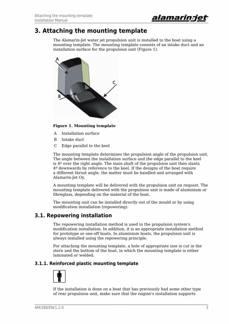
3. Attaching the mounting templateThe Alamarin-Jet water jet propulsion unit is installed to the boat using amounting template. The mounting template consists of an intake duct and aninstallation surface for the propulsion unit (Figure 1).
Figure 1. Mounting template
A Installation surfaceB Intake ductC Edge parallel to the keel
The mounting template determines the propulsion angle of the propulsion unit.The angle between the installation surface and the edge parallel to the keelis 4º over the right angle. The main shaft of the propulsion unit then slants4º downwards by reference to the keel. If the designs of the boat requirea different thrust angle, the matter must be handled and arranged withAlamarin-Jet Oy.
A mounting template will be delivered with the propulsion unit on request. Themounting template delivered with the propulsion unit is made of aluminium orfibreglass, depending on the material of the boat.
The mounting unit can be installed directly out of the mould or by usingmodification installation (repowering).
3.1. Repowering installationThe repowering installation method is used in the propulsion system'smodification installation. In addition, it is an appropriate installation methodfor prototype or one-off boats. In aluminium boats, the propulsion unit isalways installed using the repowering principle.
For attaching the mounting template, a hole of appropriate size is cut in thestern and the bottom of the boat, in which the mounting template is eitherlaminated or welded.
3.1.1. Reinforced plastic mounting template
If the installation is done on a boat that has previously had some other typeof rear propulsion unit, make sure that the engine's installation supports
Attaching the mounting templateInstallation Manual
6 AM/288/EN/1.2.0
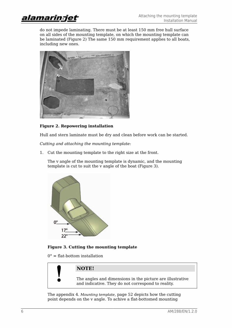
do not impede laminating. There must be at least 150 mm free hull surfaceon all sides of the mounting template, on which the mounting template canbe laminated (Figure 2) The same 150 mm requirement applies to all boats,including new ones.
Figure 2. Repowering installation
Hull and stern laminate must be dry and clean before work can be started.
Cutting and attaching the mounting template:
1. Cut the mounting template to the right size at the front.
The v angle of the mounting template is dynamic, and the mountingtemplate is cut to suit the v angle of the boat (Figure 3).
Figure 3. Cutting the mounting template
0° = flat-bottom installation
NOTE!
The angles and dimensions in the picture are illustrativeand indicative. They do not correspond to reality.
The appendix 4. Mounting template, page 52 depicts how the cuttingpoint depends on the v angle. To achive a flat-bottomed mounting
Attaching the mounting templateInstallation Manual
AM/288/EN/1.2.0 7
template, shorten the mounting template to the length of 361 mm,measured from the installation surface.
The appendix 5. Change in the v angle, page 53 shows the distance of thecutting point from the jet's installation surface.
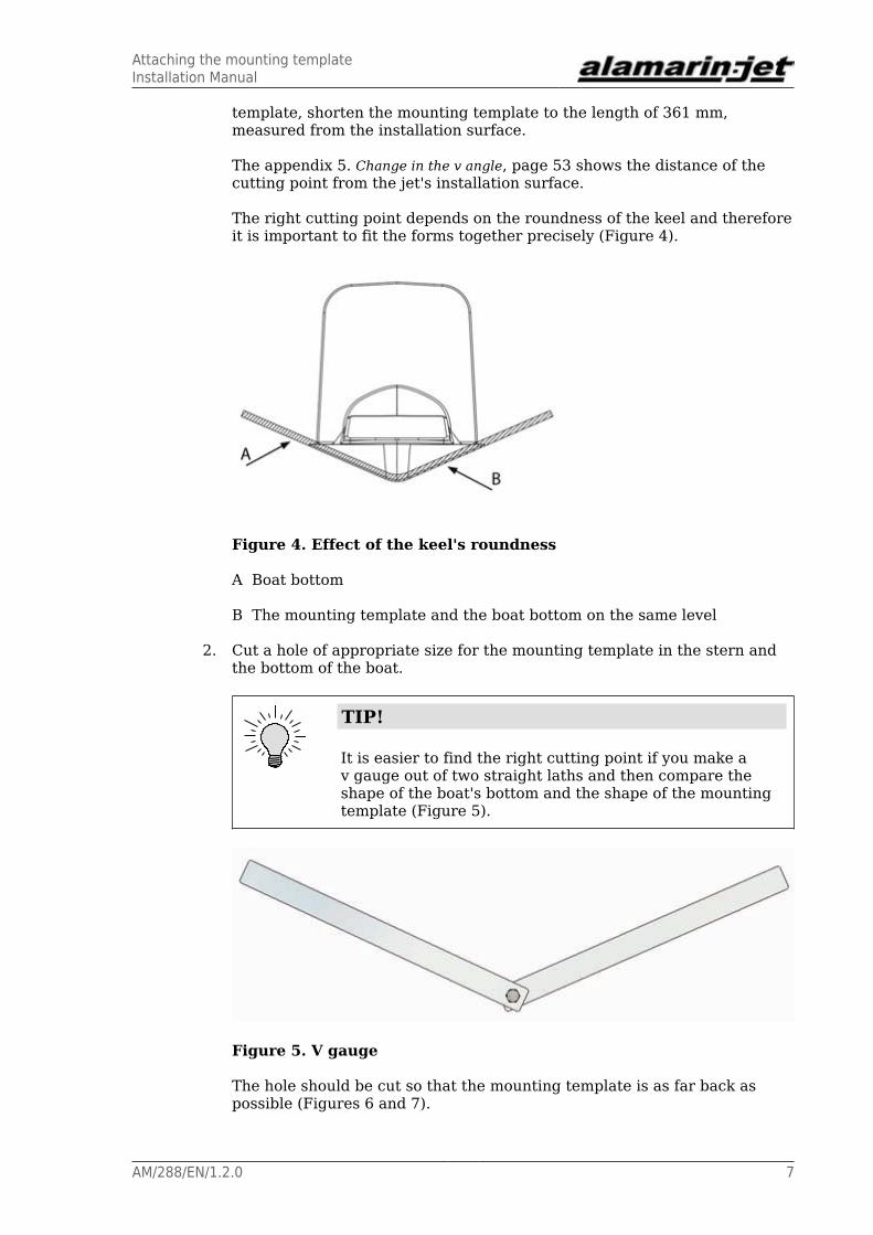
The right cutting point depends on the roundness of the keel and thereforeit is important to fit the forms together precisely (Figure 4).
Figure 4. Effect of the keel's roundness
A Boat bottom
B The mounting template and the boat bottom on the same level
2. Cut a hole of appropriate size for the mounting template in the stern andthe bottom of the boat.
TIP!
It is easier to find the right cutting point if you make av gauge out of two straight laths and then compare theshape of the boat's bottom and the shape of the mountingtemplate (Figure 5).
Figure 5. V gauge
The hole should be cut so that the mounting template is as far back aspossible (Figures 6 and 7).

Attaching the mounting templateInstallation Manual
8 AM/288/EN/1.2.0
Figure 6. Mounting template hole
Figure 7. Mounting template gap
A The bottom part of the mounting template must be level with the inner surface of the stern (the mounting template can also be embedded deeper into the hull, see Chapter 3.1.3. Embedding the mounting template to the hull of the boat, page 13).
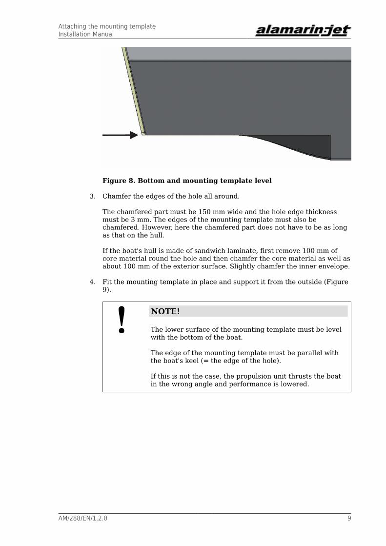
The mounting template must be on the same level with the bottom ofthe boat (Figure 8). The gap between the mounting template and thehull should be fitted so that it is as small as possible. A gap of 2–5 mm isacceptable.
Attaching the mounting templateInstallation Manual
AM/288/EN/1.2.0 9
Figure 8. Bottom and mounting template level
3. Chamfer the edges of the hole all around.
The chamfered part must be 150 mm wide and the hole edge thicknessmust be 3 mm. The edges of the mounting template must also bechamfered. However, here the chamfered part does not have to be as longas that on the hull.
If the boat's hull is made of sandwich laminate, first remove 100 mm ofcore material round the hole and then chamfer the core material as well asabout 100 mm of the exterior surface. Slightly chamfer the inner envelope.
4. Fit the mounting template in place and support it from the outside (Figure9).
NOTE!
The lower surface of the mounting template must be levelwith the bottom of the boat.
The edge of the mounting template must be parallel withthe boat's keel (= the edge of the hole).
If this is not the case, the propulsion unit thrusts the boatin the wrong angle and performance is lowered.
Attaching the mounting templateInstallation Manual
10 AM/288/EN/1.2.0
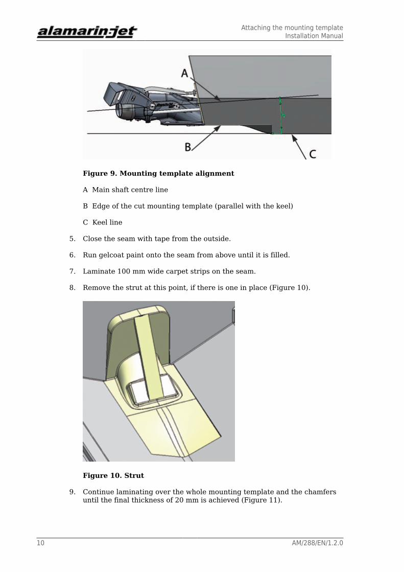
Figure 9. Mounting template alignment
A Main shaft centre line
B Edge of the cut mounting template (parallel with the keel)
C Keel line
5. Close the seam with tape from the outside.
6. Run gelcoat paint onto the seam from above until it is filled.
7. Laminate 100 mm wide carpet strips on the seam.
8. Remove the strut at this point, if there is one in place (Figure 10).
Figure 10. Strut
9. Continue laminating over the whole mounting template and the chamfersuntil the final thickness of 20 mm is achieved (Figure 11).

Attaching the mounting templateInstallation Manual
AM/288/EN/1.2.0 11
Figure 11. Laminating
A Boat shell laminate
B Attachment laminate
C Mounting template laminate
D Seam
E Original gelcoat
F Seam-filling gelcoat
10. Fit engine supports and possible bracings.
11. Cut off the excess collar on the mounting template outside the stern(Figure 12).
Figure 12. Excess collar
12. Smooth the seams and paint the visible reinforced plastic surfaces withtopcoat paint.
This is important because an uncovered laminate absorbs water.

Attaching the mounting templateInstallation Manual
12 AM/288/EN/1.2.0
3.1.2. Aluminium mounting template
The aluminium mounting template is suitable for flat-bottom installation assuch. Attaching to a v bottom is done with a triangular plate (Figure 13). Thelength of the triangular plate must at least 600 mm measured in the directionof the keel.
Figure 13. Triangular plate
Attaching the mounting template:
1. Cut the mounting template to suit flat-bottom installation (section 3.1.1.Reinforced plastic mounting template, page 5, point 1).
2. Cut a suitable hole in the bottom and the stern of the boat (section 3.1.1.Reinforced plastic mounting template, page 5, stage 2).
The hole should be cut so that the mounting template is as far back aspossible. The gap between the mounting template and the hull should befitted so that it is as small as possible.
3. Chamfer the plate edges as required by general welding standards.
4. Attach the mounting template in place (section 3.1.1. Reinforced plasticmounting template, page 5, stage 4).
5. Weld the mounting template in place both on the inside and the outside,and make the seam watertight.
6. Abrade the welded seams so that they are smooth at the bottom area.
Any uneven spots at the bottom must be trimmed by caulking, for example.
7. Paint the mounting template with two-component paint suitable forpainting aluminium.
Follow the paint manufacturer's instructions.
Attaching the mounting templateInstallation Manual
AM/288/EN/1.2.0 13
CAUTION!
Painting is important, because the intake duct is castaluminium.
The structure of cast aluminium is porous and it canabsorb water. This can accelerate the corrosion process.
The material of the cast section of the aluminium mounting template: AlSi7Mg
The material of the plate section: AlMg3
Welding filler metal: AlMg5
3.1.3. Embedding the mounting template to the hull of the boat
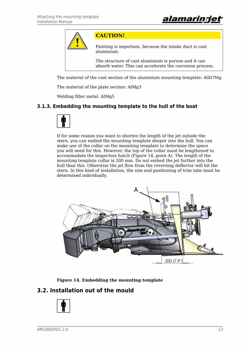
If for some reason you want to shorten the length of the jet outside thestern, you can embed the mounting template deeper into the hull. You canmake use of the collar on the mounting template to determine the spaceyou will need for this. However, the top of the collar must be lengthened toaccommodate the inspection hatch (Figure 14, point A). The length of themounting template collar is 200 mm. Do not embed the jet further into thehull than this. Otherwise the jet flow from the reversing deflector will hit thestern. In this kind of installation, the size and positioning of trim tabs must bedetermined individually.
Figure 14. Embedding the mounting template
3.2. Installation out of the mould

Attaching the mounting templateInstallation Manual
14 AM/288/EN/1.2.0
If you want to produce one type of boat with several varying propulsion unitoptions, it is possible to make a mould of the mounting template and fit itto the standard hull mould (Figure 15). This speeds up installation of thepropulsion unit without adding to mould expenses.
The mould for the mounting template is made from a mounting templateprovided by Alamarin-Jet Oy. In double installations, two moulds must be madefor both sides of the hull.
CAUTION!
Prepare the mounting template to fit exactly in the boat'smould. This must be done carefully, as inaccuracies (bulges)are copied also to the final boat and result in deterioration ofboat performance.
Figure 15. Making a negative of the mounting template
3.2.1. Removable mounting templateIf you use a removable mounting template, you can use the boat's hull mouldin both jet installation and rear propulsion unit installation. There are threestages in preparing and installing a removable mounting template:
1. Make a negative (mould) of the mounting template.
2. Adapt the negative to fit the mould exactly.
3. Install the mounting template on the boat.
All the stages, except for the first stage of processsing the negative, apply bothto single and double installations.
Processing the negative:
1. Cut the excess fibreglass off the mould of the mounting template.
This only applies to double installation.
2. Cut the collar of the mounting template in accordance with the stern of themould.
The collar must be cut carefully and correctly. If the collar is not cutcorrectly, the consequence is that the intake duct position is wrong. Theedge of the intake duct must be parallel with the keel.

Attaching the mounting templateInstallation Manual
AM/288/EN/1.2.0 15
In double installations, this means cutting according to Figure 16 when thestern is not vertical.
Figure 16. Cutting the collar (double installation)
3. Sharpen the front edge and the sides of the intake duct negative so that nothick edge is left between the boat mould and the negative (Figure 17).
If this is not done, the thick edge is copied to the final boat and the boat'sperformance may suffer.
Figure 17. Sharpened negative
4. Reinforce the collar of the mounting template negative with a woodenframe, a plywood plate or for example with urethane foam (Figure 18).
This way the collar will not bend inward during laminating.

Attaching the mounting templateInstallation Manual
16 AM/288/EN/1.2.0
Figure 18. Reinforced collar
Installing the mounting template on the boat :
1. Fit the mounting template negative in the boat mould so that the intakeduct is parallel with the keel (Figure 16).
TIP!
It is advisable to mark the place of the mounting templateon the boat mould after the first installation. This makesfitting the mounting template faster and easier the nexttime.
2. Attach the mounting template negative on the boat's mould with tape orother temporary method.
Make sure that there are no big notches in the seams of the negative andthe boat's mould. A notch caused by tape is not detrimental.
For the part of the jet's mounting template, the boat's mould is now ready forlaminating. When laminating the boat, the paint that is spread first (gelcoat)solidifies the mounting template in place.
CAUTION!
Double installation!
After the boat has been laminated and is ready to be removedfrom the mould, the mounting template negatives detach withthe boat. The mounting templates are removed from the boatfor the next installation.
3.2.2. Fixed mounting template
The mounting template can also be fixed to the mould. In this case, the boat'shull mould can only be used in jet installation. In double installation, theboat's mould must be two-piece in order to make separation of the mountingtemplates possible. A two-piece mould is not necessarily needed for singleinstallation.
Attaching the mounting templateInstallation Manual
AM/288/EN/1.2.0 17
Double installation
1. Make two negatives of the mounting template.
2. Fit and install the mounting templates on the boat's mould (section 3.2.1.Removable mounting template, page 14).
3. Laminate the rear end of the boat in the mould and remove it.
4. Remove the mounting templates.
5. Make a separate mould of the rear end.
Single installation
1. Make a negative of the mounting template.
2. Fit and install the mounting template on the boat mould (section 3.2.1.Removable mounting template, page 14).
3. Laminate the hull of the boat in the mould and remove it.
4. Make a new mould of the hull.

Attaching the mounting templateInstallation Manual
18 AM/288/EN/1.2.0

Attaching the propulsion unitInstallation Manual
AM/288/EN/1.2.0 19
4. Attaching the propulsion unitThe propulsion unit is attached to the boat one part at a time. Attaching iscarried out in the following order:
1. Propulsion unit body
2. Lubrication system for the bearings
3. Hydraulic cylinder
4. hydraulic pump
5. Cooling line for hydraulic cylinder oil
6. Grass rake
7. Raw water cooling line
4.1. Preparations
Holes must be made on the installation surface of the mounting template forattaching the propulsion unit and for the required bushings. An aluminiummounting template is already equipped with the required holes.
Sawing/drilling the holes is carried out with the drilling templates that comewith delivery.
Drilling the holes:
1. Set the template against the installation surface so that the texts arevisible, and centre the template in relation to the ready-drilled centre hole.
2. Mark the holes and drill them.
The gauge has only a centre hole for large holes, and they are drilled tothe right diameter with a hole saw. The name of the bushing and the finaldiameter are marked on the template for clarity (Figure 19).
TIP!
It is advisable to first make one hole and use it to attachthe drilling template to the stern. This way it stays in placewhen drilling the other holes.

Attaching the propulsion unitInstallation Manual
20 AM/288/EN/1.2.0
Figure 19. Drilling template
Before installation, make sure that
1. The installation surface is straight and clean.
2. The holes are drilled/sawn correctly.
3. Stern laminate does not come in the way of the propulsion unit and itsauxiliaries, which means that the laminate is not too thick.
4. The following items have been removed from the propulsion unit:
• Hydraulic cylinder
• Steering shaft
• hydraulic pump
• Lubrication hose or cartridge for the rear bearing
WARNING!
When removing the hydraulic cylinder, the piston rod mustnot twist 180°. The cylinder will not work properly if thatoccurs.
4.2. Attaching the body
Attaching the body of the propulsion unit to the boat:
1. Spread sealing compound (such as Sikaflex 221) on the fixing area (Figure20, point A).
Attaching the propulsion unitInstallation Manual
AM/288/EN/1.2.0 21
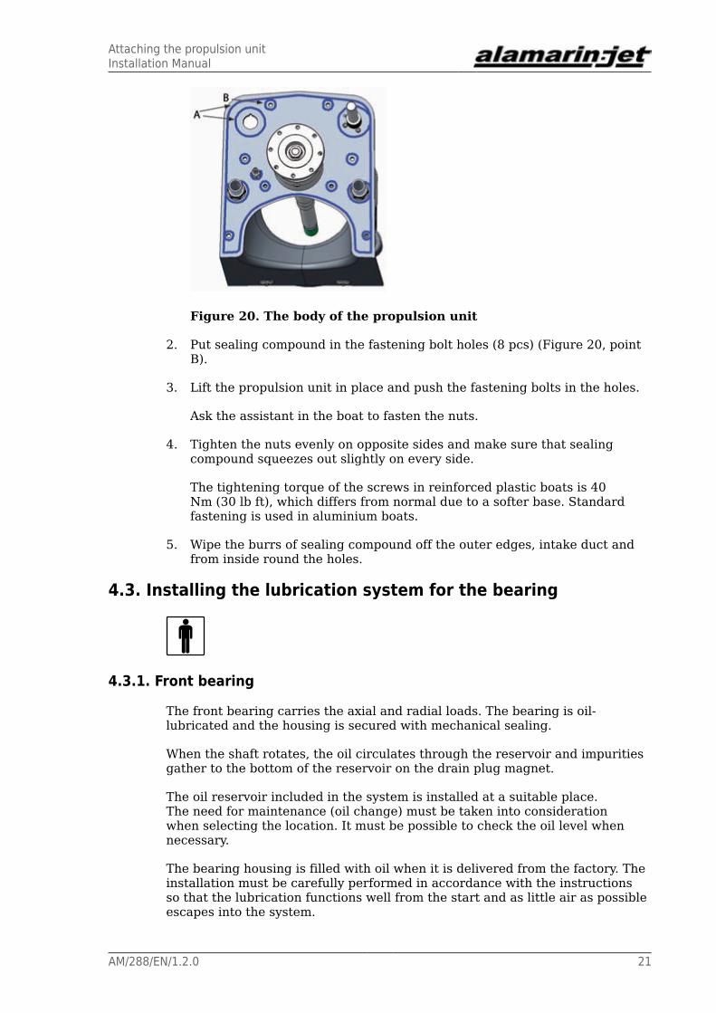
Figure 20. The body of the propulsion unit
2. Put sealing compound in the fastening bolt holes (8 pcs) (Figure 20, pointB).
3. Lift the propulsion unit in place and push the fastening bolts in the holes.
Ask the assistant in the boat to fasten the nuts.
4. Tighten the nuts evenly on opposite sides and make sure that sealingcompound squeezes out slightly on every side.
The tightening torque of the screws in reinforced plastic boats is 40Nm (30 lb ft), which differs from normal due to a softer base. Standardfastening is used in aluminium boats.
5. Wipe the burrs of sealing compound off the outer edges, intake duct andfrom inside round the holes.
4.3. Installing the lubrication system for the bearing
4.3.1. Front bearing
The front bearing carries the axial and radial loads. The bearing is oil-lubricated and the housing is secured with mechanical sealing.
When the shaft rotates, the oil circulates through the reservoir and impuritiesgather to the bottom of the reservoir on the drain plug magnet.
The oil reservoir included in the system is installed at a suitable place.The need for maintenance (oil change) must be taken into considerationwhen selecting the location. It must be possible to check the oil level whennecessary.
The bearing housing is filled with oil when it is delivered from the factory. Theinstallation must be carefully performed in accordance with the instructionsso that the lubrication functions well from the start and as little air as possibleescapes into the system.
Attaching the propulsion unitInstallation Manual
22 AM/288/EN/1.2.0
Installing the front bearing housing:
1. Make sure that the oil reservoir is installed (section 4.5. Attaching thehydraulic pump, page 29).
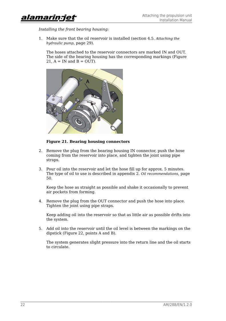
The hoses attached to the reservoir connectors are marked IN and OUT.The side of the bearing housing has the corresponding markings (Figure21, A = IN and B = OUT).
Figure 21. Bearing housing connectors
2. Remove the plug from the bearing housing IN connector, push the hosecoming from the reservoir into place, and tighten the joint using pipestraps.
3. Pour oil into the reservoir and let the hose fill up for approx. 5 minutes.The type of oil to use is described in appendix 2. Oil recommendations, page50.
Keep the hose as straight as possible and shake it occasionally to preventair pockets from forming.
4. Remove the plug from the OUT connector and push the hose into place.Tighten the joint using pipe straps.
Keep adding oil into the reservoir so that as little air as possible drifts intothe system.
5. Add oil into the reservoir until the oil level is between the markings on thedipstick (Figure 22, points A and B).
The system generates slight pressure into the return line and the oil startsto circulate.

Attaching the propulsion unitInstallation Manual
AM/288/EN/1.2.0 23
Figure 22. Oil level in the reservoir
4.3.2. Rear bearing
The bearing at the rear end of the shaft is lubricated from point A indicated inFigure 23. The lubricant flows through the hoses and casting channels in thepropulsion unit to the rear end bearing housing. A line is formed from point Ato automatic lubrication with a plastic hose (B). Alternatively, there can be agrease nipple at the end of the hose.
Figure 23. Rear end bearing grease tube
Note that during the propulsion unit installation the lubrication hose (B) isremoved but it must be put back when the propulsion unit is in place.
The automatic lubrication unit (Figure 24) decreases the need for maintenancebecause it feeds grease to the rear bearing each time the jet's main shaft
Attaching the propulsion unitInstallation Manual
24 AM/288/EN/1.2.0
rotates. The grease going to the rear bearing lubricates the bearing, and italso prevents water from leaking into the bearing housing. The amount ofgrease is adjusted with a screw in the hydraulic cylinder which tightens thespring (Figure 23, point C). When you loosen the screw, the amount of greasedecreases.
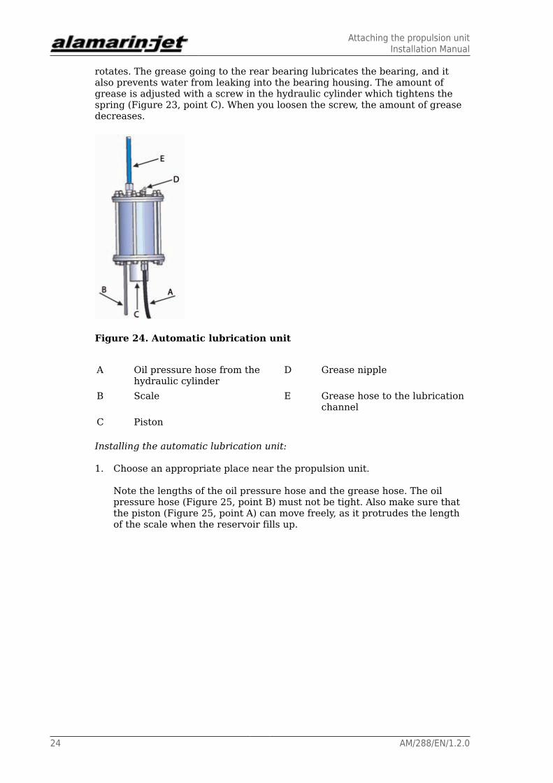
Figure 24. Automatic lubrication unit
A Oil pressure hose from thehydraulic cylinder
D Grease nipple
B Scale E Grease hose to the lubricationchannel
C Piston
Installing the automatic lubrication unit:
1. Choose an appropriate place near the propulsion unit.
Note the lengths of the oil pressure hose and the grease hose. The oilpressure hose (Figure 25, point B) must not be tight. Also make sure thatthe piston (Figure 25, point A) can move freely, as it protrudes the lengthof the scale when the reservoir fills up.
Attaching the propulsion unitInstallation Manual
AM/288/EN/1.2.0 25
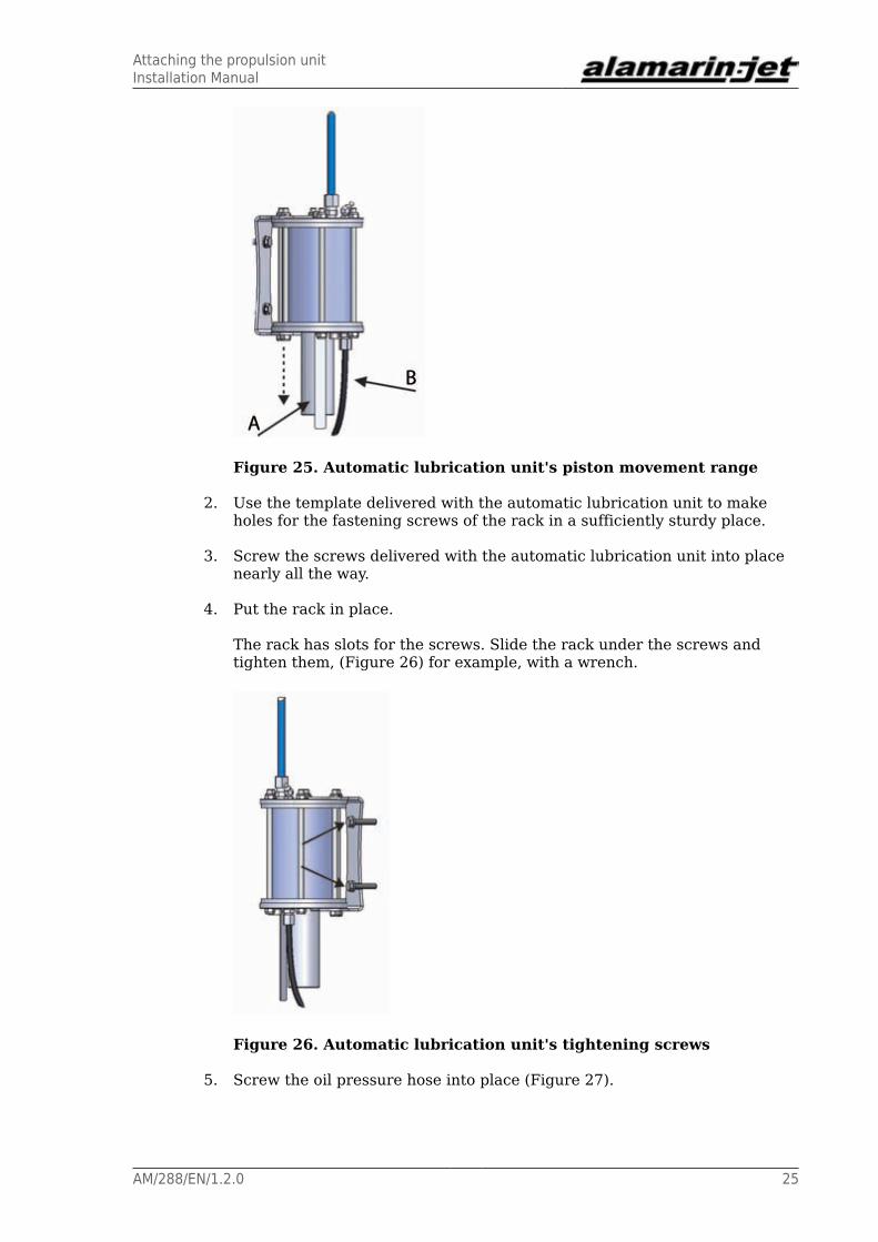
Figure 25. Automatic lubrication unit's piston movement range
2. Use the template delivered with the automatic lubrication unit to makeholes for the fastening screws of the rack in a sufficiently sturdy place.
3. Screw the screws delivered with the automatic lubrication unit into placenearly all the way.
4. Put the rack in place.
The rack has slots for the screws. Slide the rack under the screws andtighten them, (Figure 26) for example, with a wrench.
Figure 26. Automatic lubrication unit's tightening screws
5. Screw the oil pressure hose into place (Figure 27).

Attaching the propulsion unitInstallation Manual
26 AM/288/EN/1.2.0
Figure 27. Attaching the oil pressure hose
6. Fit the grease hose to the nipple in the body (Figure 23, point A).
Feeding
You can adjust the feed as follows:
• If the automatic lubrication unit is feeding too much grease (the reservoirgets empty too soon), decrease the pressure by loosening the adjustingscrew (Figure 23, point C).
• If the automatic lubrication unit is not feeding grease to the rear bearing(cold conditions, thick grease type), increase the pressure by tightening theadjusting screw (Figure 23, point C).
The amount of grease fed to the rear bearing must be 0.1 l/100 h (6 cu in/100h). The grease volume in the unit is 0.3 l (18 cu in). With these settings, thereservoir will empty in 300 hours. If you notice that the reservoir emptiesslower or faster than this, adjust the pressure to the desired direction.
You can fill the reservoir by pushing grease into it with a grease gun throughthe nipple (Figure 24, point D). Then the piston (Figure 25, point A) willprotrude out of the reservoir.
The properties of the grease to use are described in Appendix 1. Greaserecommendations, page 49.
4.4. Attaching the hydraulic cylinder
Attaching the hydraulic cylinder:
1. Make sure that the hydraulic cylinder goes in place without sealingcompound.
2. Make sure that the wedge is in place (Figure 28, point A).
The wedge ensures that the cylinder is in the right position and that themovement range remains correct.

Attaching the propulsion unitInstallation Manual
AM/288/EN/1.2.0 27
Figure 28. Hydraulic cylinder wedge
3. Spread sealing compound (such as Sikaflex 221) into point B, as indicatedin Figure 28 so that it seals the bushing.
4. Push the cylinder through the hole, insert the spacer (Figure 29, point A)into its place, and tighten the screw (Figure 29, point B).
The tightening torque for the large nut is 100 Nm (74 lb ft).
Figure 29. Hydraulic cylinder spacer and nut
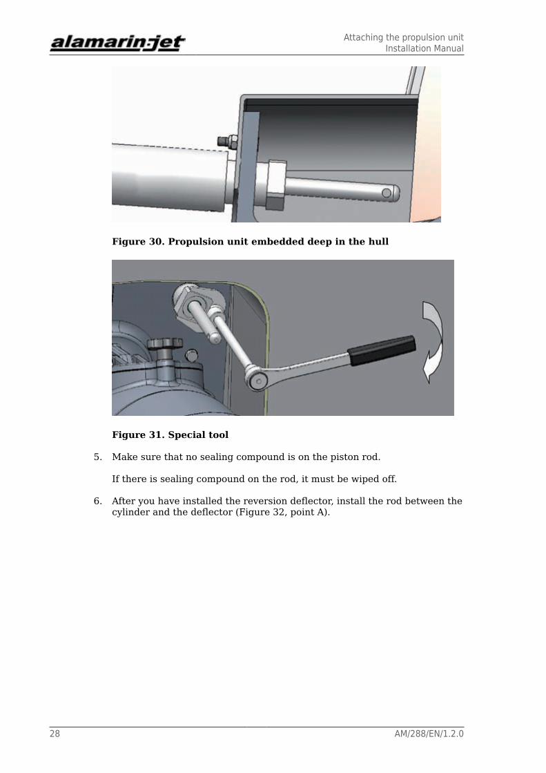
There is a special tool available for screwing the nuts that can be usedwhen the propulsion unit is embedded deep in the hull (Figures 30 and31).
Attaching the propulsion unitInstallation Manual
28 AM/288/EN/1.2.0
Figure 30. Propulsion unit embedded deep in the hull
Figure 31. Special tool
5. Make sure that no sealing compound is on the piston rod.
If there is sealing compound on the rod, it must be wiped off.
6. After you have installed the reversion deflector, install the rod between thecylinder and the deflector (Figure 32, point A).

Attaching the propulsion unitInstallation Manual
AM/288/EN/1.2.0 29
Figure 32. The rod between the hydraulic cylinder and thereversing deflector
7. Install the zinc anode to the piston rod.
Ensure that the zinc anode (Figure 32, point B) does not prevent thedeflector from moving all the way up.
4.5. Attaching the hydraulic pump
Attaching the hydraulic pump:
1. Install the pump rack and the pump with screws to the front surface of thebearing housing.
Leave the screws slightly loose.
There are a total of four screws, two on each side (Figure 33, points A andB).
Figure 33. Attaching the hydraulic pump
2. Fit the belt in place.
Attaching the propulsion unitInstallation Manual
30 AM/288/EN/1.2.0
3. Lift the rack by cranking it from point C indicated in Figure 33.
4. Tighten the screws.
The tightening torque is 46 Nm (approx. 15 lb-ft.).
5. Install the pressure hose to connectors D and E (Figure 33).
6. Install the reservoir hose to connector F (Figure 33).
7. Install the oil reservoir rack to a suitable place above the pump.
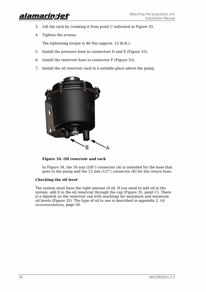
Figure 34. Oil reservoir and rack
In Figure 34, the 16 mm (5/8'') connector (A) is intended for the hose thatgoes to the pump and the 12 mm (1/2'') connector (B) for the return hose.
Checking the oil level
The system must have the right amount of oil. If you need to add oil to thesystem, add it in the oil reservoir through the cap (Figure 35, point C). Thereis a dipstick on the reservoir cap with markings for maximum and minimumoil levels (Figure 35). The type of oil to use is described in appendix 2. Oilrecommendations, page 50.
Attaching the propulsion unitInstallation Manual
AM/288/EN/1.2.0 31
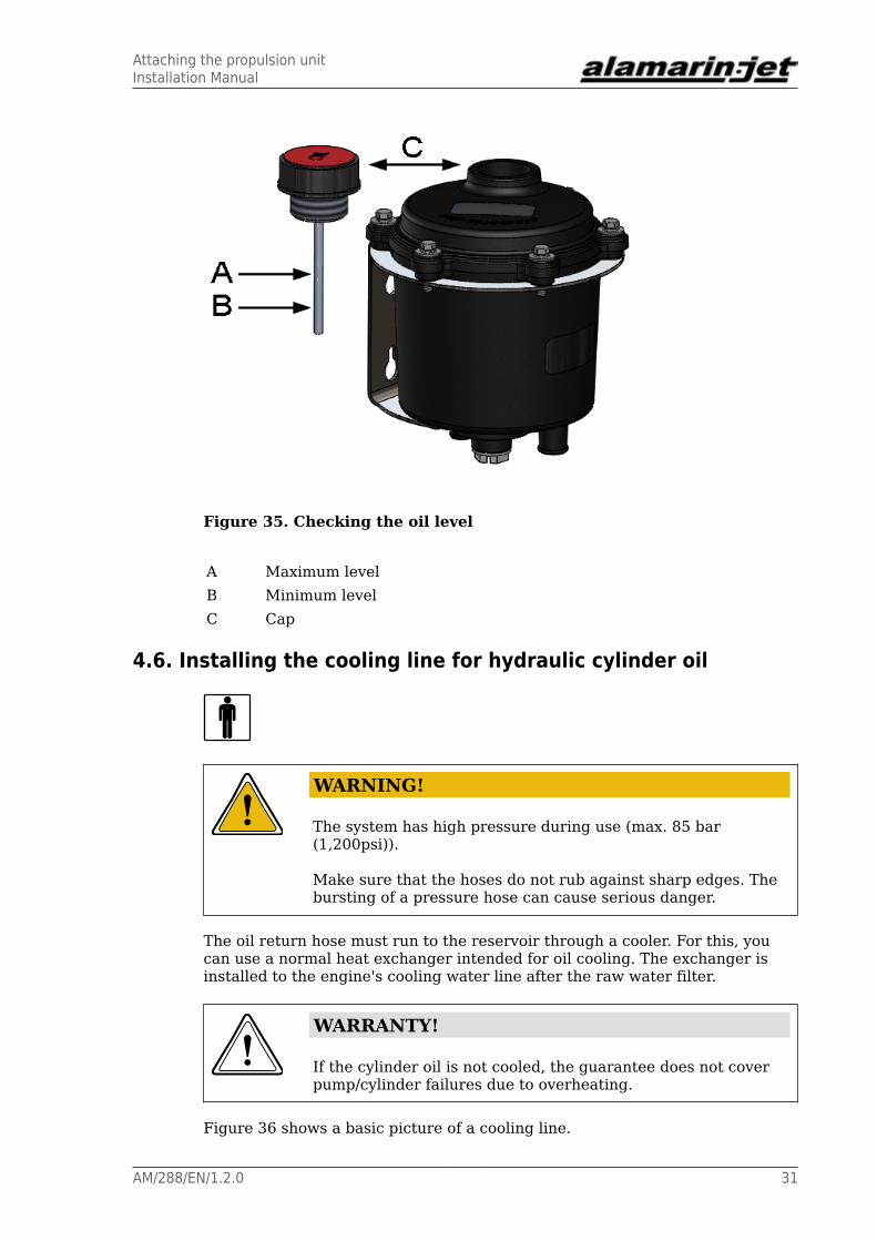
Figure 35. Checking the oil level
A Maximum levelB Minimum levelC Cap
4.6. Installing the cooling line for hydraulic cylinder oil
WARNING!
The system has high pressure during use (max. 85 bar(1,200psi)).
Make sure that the hoses do not rub against sharp edges. Thebursting of a pressure hose can cause serious danger.
The oil return hose must run to the reservoir through a cooler. For this, youcan use a normal heat exchanger intended for oil cooling. The exchanger isinstalled to the engine's cooling water line after the raw water filter.
WARRANTY!
If the cylinder oil is not cooled, the guarantee does not coverpump/cylinder failures due to overheating.
Figure 36 shows a basic picture of a cooling line.

Attaching the propulsion unitInstallation Manual
32 AM/288/EN/1.2.0
Figure 36. Cooling line
The hoses must run from the cooler connectors (Figure 36, point A) tothe cylinder's return connector (Figure 36, point B) and the oil reservoir(Figure 36, point C).
Note the following when installing the line:
• The cooler should be installed so that the inlet and outlet connectors pointupwards. This advances the exit of air from the system.
• The hose that runs from the cooler to the reservoir should be fitted so that itdoes not have any “swan necks”.
When you use the propulsion unit for the first time (=after engine installation),check the movement of the reversing deflector and observe the oil level. If theoil level continues to lower even after the line is filled, there is a leak in thesystem. Find the leak and fix the problem.
4.7. Attaching the grass rake
The grass rake (Figure 37) is attached in front of the intake opening with fourscrews.

Attaching the propulsion unitInstallation Manual
AM/288/EN/1.2.0 33
Figure 37. Grass rake
Attaching the grass rake:
1. Seal the fixing area in the same manner as when installing the propulsionunit body.
2. Fit the grass rake in place in the intake duct and tighten the screws inplace.
The normal tightening torque for an M8 screw is 23 Nm (17 lb ft). Thetightening torque of the screws in reinforced plastic boats is only 20 Nm(15 lb ft).
4.8. Installing the raw water cooling line
Cooling water for the engine can be taken from the pressure face of thepropulsion unit. The propulsion unit has two raw water intakes as standardequipment for this purpose. They are located on both sides of the bearinghousing (Figure 38).
Figure 38. Raw water intakes
The intakes have a G1" external thread. The line to the engine can beconstructed using normal pipe parts or can be plugged into the engine using

Attaching the propulsion unitInstallation Manual
34 AM/288/EN/1.2.0
the plugs delivered with the propulsion unit. The raw water intakes can also beused for other purposes that require pressure water.
The design pressure of the line is 10 bar, but the actual pressure depends onthe impeller type, running speed and the line structure.
When constructing the raw water cooling line
• Note the engine manufacturer's recommendations regarding the coolingwater feed.
• If necessary, throttle the line sufficiently before the engine and remove thethrottles after the engine.
Line pressure should be measured before the engine, and the pressure shouldbe adjusted in accordance with the engine manufacturer's instructions.
The hose joints must be durable enough. If the hose breaks or the joint comesoff, the engine room may fill with water, the engine may break, or the boat mayeven sink.
Dry running of the jet (when the boat is not in water) can be performedwithout restriction.
CAUTION!
However, always observe the manufacturers' otherinstructions for dry running.
The operation of the raw water line is depicted in Figure 39.
Figure 39. Raw water line
Attaching the propulsion unitInstallation Manual
AM/288/EN/1.2.0 35
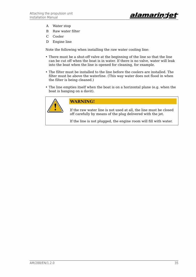
A Water stopB Raw water filterC CoolerD Engine line
Note the following when installing the raw water cooling line:
• There must be a shut-off valve at the beginning of the line so that the linecan be cut off when the boat is in water. If there is no valve, water will leakinto the boat when the line is opened for cleaning, for example.
• The filter must be installed to the line before the coolers are installed. Thefilter must be above the waterline. (This way water does not flood in whenthe filter is being cleaned.)
• The line empties itself when the boat is on a horizontal plane (e.g. when theboat is hanging on a davit).
WARNING!
If the raw water line is not used at all, the line must be closedoff carefully by means of the plug delivered with the jet.
If the line is not plugged, the engine room will fill with water.

Attaching the propulsion unitInstallation Manual
36 AM/288/EN/1.2.0

Installing the control systemInstallation Manual
AM/288/EN/1.2.0 37
5. Installing the control systemThe propulsion unit's control system must be installed correctly. Incorrectinstallation of the system will reduce performance.
Because the propulsion unit can be used with or without gears, there arevarious ways of installation.
Installation Options
• The gear is located between the propulsion unit and the engine.
A control with two levers, one of which controls the gearbox and theaccelerator and the other the reversing deflector.
• Between the propulsion unit and the engine, there is only the intermediateshaft.
A control with two levers, one of which controls the accelerator and theother the reversing deflector.
• Two propulsion units with a gear.
Two separate controls with two levers or one control with four levers. Thetwo adjacent levers are used to control the gears and accelerators of bothengines, and the other two to control the reversing deflectors.
WARNING!
The movement of the reversing deflector must always becontrolled with a separate lever. Otherwise the propulsion unitdoes not function correctly.
5.1. Connecting the reversing deflector to the control system
The control cylinder of the reversing deflector is used with the lever (Figure40, point A) that is at the end of the cylinder. The lever has a cable terminalwhen it is delivered from the factory. However, the cable's inlet direction canbe different than the standard direction of the cable support (Figure 40, pointB). You can turn the cable support plate to point to the desired direction inaccordance with the cable's inlet direction.

Installing the control systemInstallation Manual
38 AM/288/EN/1.2.0
Figure 40. Hydraulic cylinder
Changing the position of the cable support:
1. If the control cable is attached, detach the end of the cable (Figure 40,point C) from the cylinder's operating lever and detach the cable fastenerfrom the support plate (Figure 40, point D).
2. Loosen the operating lever's fastening screw and pull the lever off theshaft (Figure 41).
Figure 41. Removing the operating lever
3. Open the fastening screws (four in total, Figure 42) that attach the supportplate to the cylinder.
Note that the same screws attach the valve housing to the cylinder pipe.However, if you are careful the valve housing will remain in the cylinderpipe.
Installing the control systemInstallation Manual
AM/288/EN/1.2.0 39
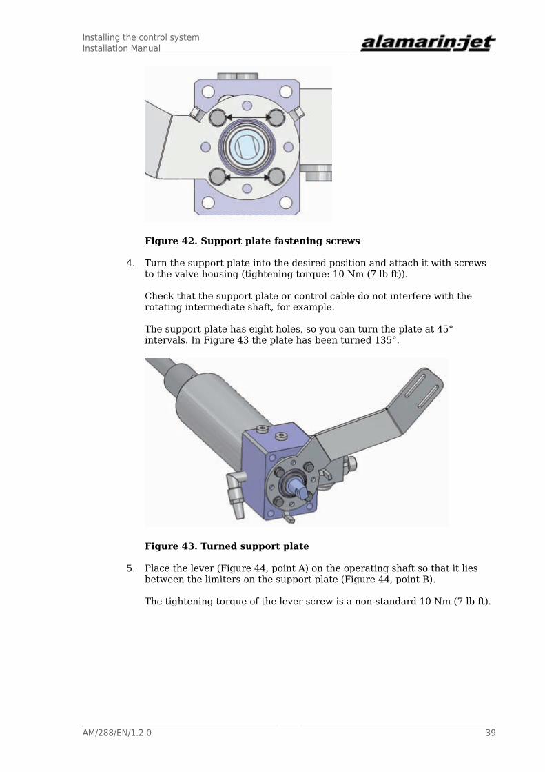
Figure 42. Support plate fastening screws
4. Turn the support plate into the desired position and attach it with screwsto the valve housing (tightening torque: 10 Nm (7 lb ft)).
Check that the support plate or control cable do not interfere with therotating intermediate shaft, for example.
The support plate has eight holes, so you can turn the plate at 45°intervals. In Figure 43 the plate has been turned 135°.
Figure 43. Turned support plate
5. Place the lever (Figure 44, point A) on the operating shaft so that it liesbetween the limiters on the support plate (Figure 44, point B).
The tightening torque of the lever screw is a non-standard 10 Nm (7 lb ft).

Installing the control systemInstallation Manual
40 AM/288/EN/1.2.0
Figure 44. Attaching the operating lever
6. Attach the control cable with a fastener (Figure 44, point C) to the supportplate and with an angle joint (Figure 44, point D) to the lever ball screw.
The height of the screw attachments at the end of the lever affects thecontrol system stroke length. See appendix 8. Lever movement ranges, page57.
See the cylinder adjustment instructions in chapter 5.1.2. Cylinderadjustment, page 41.
5.1.1. Connecting the control cables
The control cables are connected from the control system to the reversingdeflector, as indicated in pictures 45–47.
Idle running
Both levers (B and C) are in the centre (Figure 45)
Figure 45. Idle running
A AcceleratorB Reversing deflectorC Steering cylinder's operating lever
Installing the control systemInstallation Manual
AM/288/EN/1.2.0 41
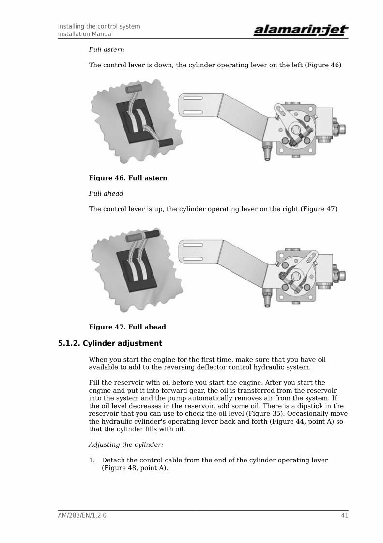
Full astern
The control lever is down, the cylinder operating lever on the left (Figure 46)
Figure 46. Full astern
Full ahead
The control lever is up, the cylinder operating lever on the right (Figure 47)
Figure 47. Full ahead
5.1.2. Cylinder adjustment
When you start the engine for the first time, make sure that you have oilavailable to add to the reversing deflector control hydraulic system.
Fill the reservoir with oil before you start the engine. After you start theengine and put it into forward gear, the oil is transferred from the reservoirinto the system and the pump automatically removes air from the system. Ifthe oil level decreases in the reservoir, add some oil. There is a dipstick in thereservoir that you can use to check the oil level (Figure 35). Occasionally movethe hydraulic cylinder's operating lever back and forth (Figure 44, point A) sothat the cylinder fills with oil.
Adjusting the cylinder:
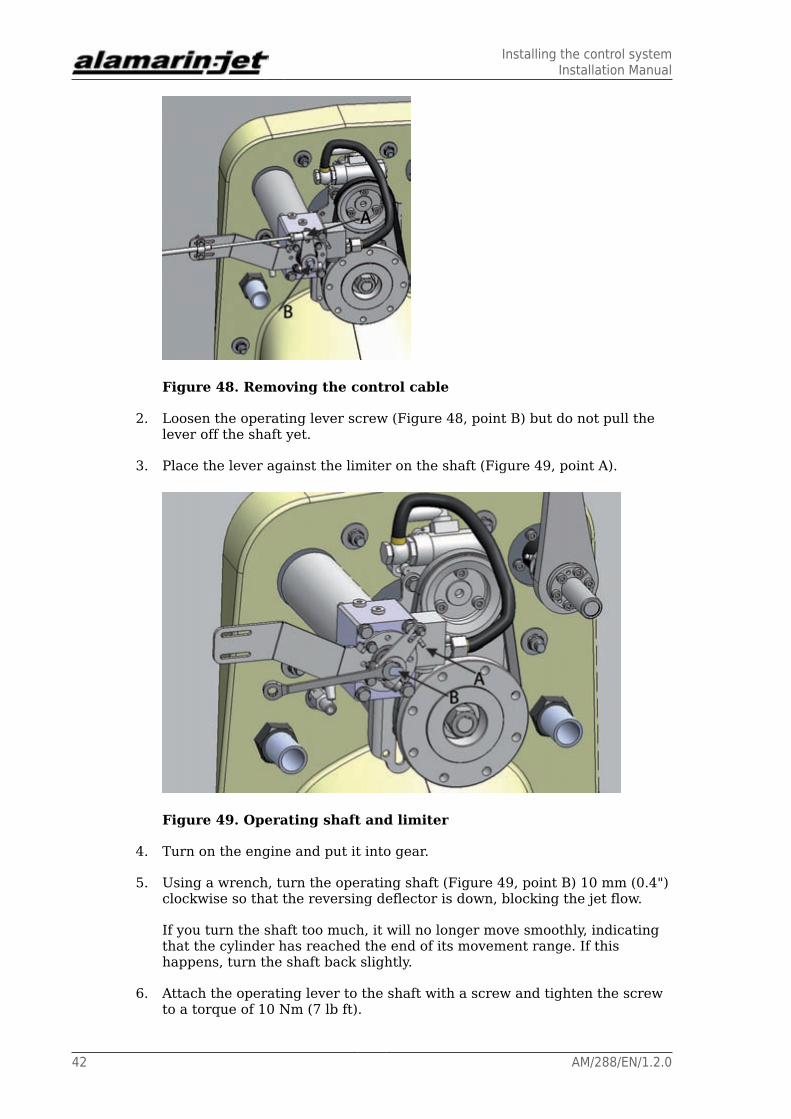
1. Detach the control cable from the end of the cylinder operating lever(Figure 48, point A).
Installing the control systemInstallation Manual
42 AM/288/EN/1.2.0
Figure 48. Removing the control cable
2. Loosen the operating lever screw (Figure 48, point B) but do not pull thelever off the shaft yet.
3. Place the lever against the limiter on the shaft (Figure 49, point A).
Figure 49. Operating shaft and limiter
4. Turn on the engine and put it into gear.
5. Using a wrench, turn the operating shaft (Figure 49, point B) 10 mm (0.4")clockwise so that the reversing deflector is down, blocking the jet flow.
If you turn the shaft too much, it will no longer move smoothly, indicatingthat the cylinder has reached the end of its movement range. If thishappens, turn the shaft back slightly.
6. Attach the operating lever to the shaft with a screw and tighten the screwto a torque of 10 Nm (7 lb ft).

Installing the control systemInstallation Manual
AM/288/EN/1.2.0 43
Do not tighten the screw too much!
7. Attach the control cable to the screw at the end of the operating lever(Figure 48, point A).
8. Use the control system in the cabin to check that the deflector can move tothe up and down positions.
In the up position, the deflector does not block the jet flow (Figure 50). Inthe down position, the top of the reversing deflector nearly touches thesteering nozzle (Figure 51).
Figure 50. Deflector in the up position
Figure 51. Deflector in the down position
5.2. Connecting the steering nozzle to the control system
There is a lever for the operating device at the end of the nozzle control shaft(Figure 52). Operation can be hydraulic, electronic, or mechanical. The mostimportant thing with the operation of the system is that the movement rangeof the operating device suits the movement range of the lever. The movementrange of the lever has to be restricted in case the movement range of theoperating device is too long.

Installing the control systemInstallation Manual
44 AM/288/EN/1.2.0
Figure 52. Operating device lever
WARNING!
If the movement range of the nozzle operating device is toolong, the propulsion system can break down due to overload.
You can check the movement range with a special toolavailable as an accessory.
The control lever has holes ready at different heights so that differentoperating devices can be connected. See appendix 8. Lever movementranges, page 57.
Connecting the lever to the shaft
1. Clean the surfaces of the shaft and the cone sleeve of grease.
2. Put some threadlocker on to the cone sleeve screws (6 pcs) and make themfinger-tight. This way the lever can slide on the shaft and you can find thecorrect position for it.
3. Once you have found the correct position for the lever, tighten the lever onto the shaft with the cone sleeve. Tighten the cone sleeve screws evenly bytightening each screw in turn by several revolutions of the tightening ringwhile making sure that each screw is tightening the cone sleeve evenly.
Do not over-tighten the cone sleeve or the cone will stretch the outer ringof the lever. An excessively tightened cone will collapse and lose its grip.
In double installation, the operating device is installed to the steering leverof one jet and the power is transmitted to the steering of the other jet with aconnecting rod. The lenght of the connecting rod is determined by the distancebetween the jets (appendix 6. Connecting rod for double installation, page 54).

Engine installationInstallation Manual
AM/288/EN/1.2.0 45
6. Engine installation
This section deals with engine installation in relation to the propulsion unit.Otherwise engine installation must always be carried out according to theengine manufacturer's instructions.
The Alamarin-Jet 288 propulsion unit can be used with different engines eitherwith gears or with a direct connection to the flywheel adapter. The gear isselected depending on engine power and speed. Check the correct gear bycontacting a representative of Alamarin-Jet Oy.
CAUTION!
Before installing the engine, make sure that the gear possiblyconnected to it is correct. Wrong gear ratio decreases theperformance of the propulsion unit or can completely preventits use.
Aligning the engine with the propulsion unit
Correct sizing and aligning of the intermediate shaft is especially importantfor the operating life of the whole system. Different intermediate shaftsallow different angles and it is imperative that you know the manufacturer'srecommendations for maximum angles when installing.
Constant speed shaft
At both ends of the constant speed shaft, there is a joint based on ballsrolling on a spherical surface. Of the shafts used with propulsion units, anintermediate shaft like this allows the most freedom in terms of alignment. Thejoints can be at angles that are different from each other (figure 53).
Figure 53. Constant speed shaft
Cardan shaft
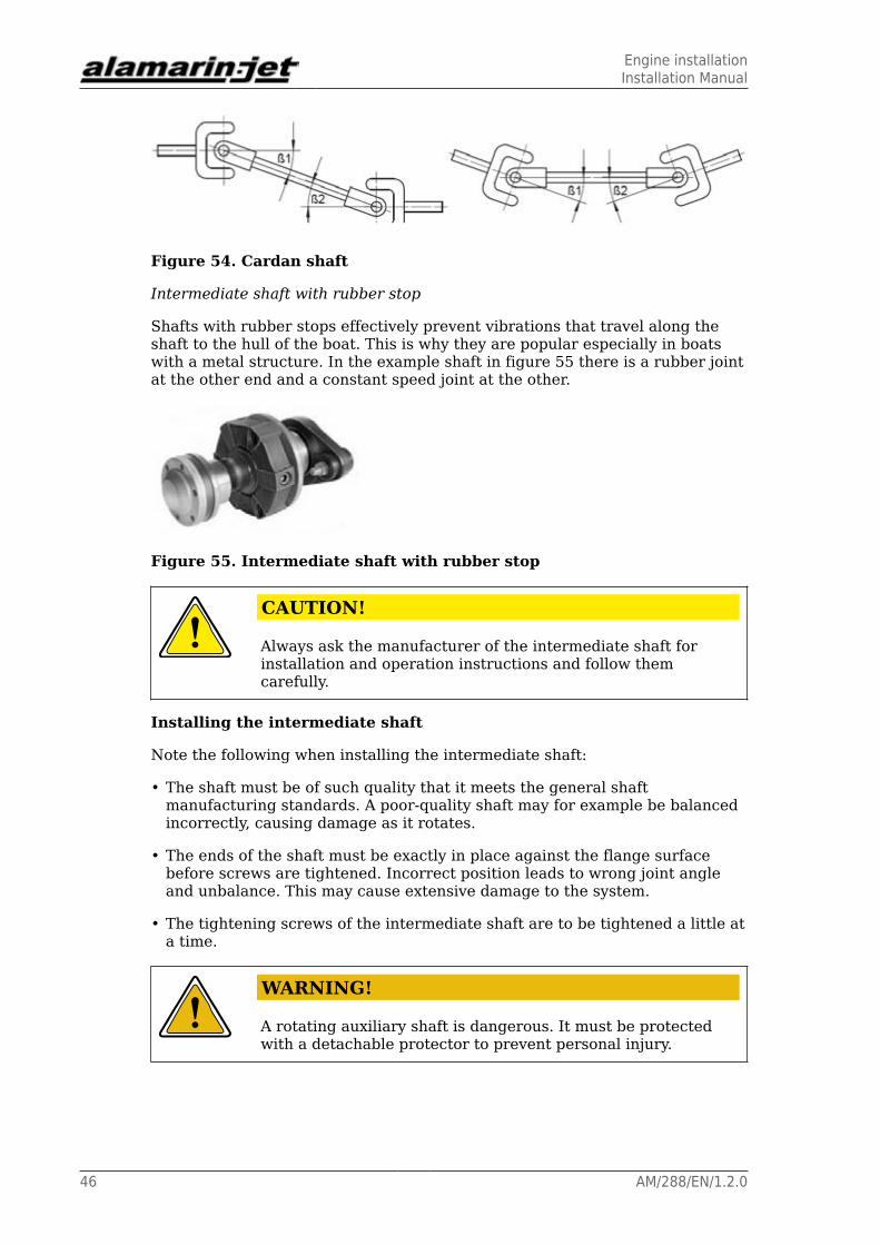
The cardan shaft joints are diagonal. This is why alignment is moredemanding. To get the shaft to rotate without vibration, the joint angles mustbe equal. Figure 54 shows examples of allowed angle configurations.
Engine installationInstallation Manual
46 AM/288/EN/1.2.0
Figure 54. Cardan shaft
Intermediate shaft with rubber stop
Shafts with rubber stops effectively prevent vibrations that travel along theshaft to the hull of the boat. This is why they are popular especially in boatswith a metal structure. In the example shaft in figure 55 there is a rubber jointat the other end and a constant speed joint at the other.
Figure 55. Intermediate shaft with rubber stop
CAUTION!
Always ask the manufacturer of the intermediate shaft forinstallation and operation instructions and follow themcarefully.
Installing the intermediate shaft
Note the following when installing the intermediate shaft:
• The shaft must be of such quality that it meets the general shaftmanufacturing standards. A poor-quality shaft may for example be balancedincorrectly, causing damage as it rotates.
• The ends of the shaft must be exactly in place against the flange surfacebefore screws are tightened. Incorrect position leads to wrong joint angleand unbalance. This may cause extensive damage to the system.
• The tightening screws of the intermediate shaft are to be tightened a little ata time.
WARNING!
A rotating auxiliary shaft is dangerous. It must be protectedwith a detachable protector to prevent personal injury.
AntifoulingInstallation Manual
AM/288/EN/1.2.0 47
7. Antifouling
If the boat is going to be used in waterways where the growth and stickingof organisms around the boat’s bottom and the propulsion unit is heavy, thepropulsion unit can be painted with antifouling paint after installation.
Generally speaking, antifouling paints are based on various solublesubstances, for example copper. Because the propulsion unit is made mainlyof aluminium, copper forms a highly unfavourable galvanic couple with thepropulsion unit. The aluminium starts to corrode because it functions as ananode.
WARNING!
If copper bearing antifouling paint is used for paintingthe propulsion unit, the result will be heavy corrosion anddestruction of the propulsion unit.
Do not use any other antifouling paints for painting thepropulsion unit except those intended for aluminium surfaces!
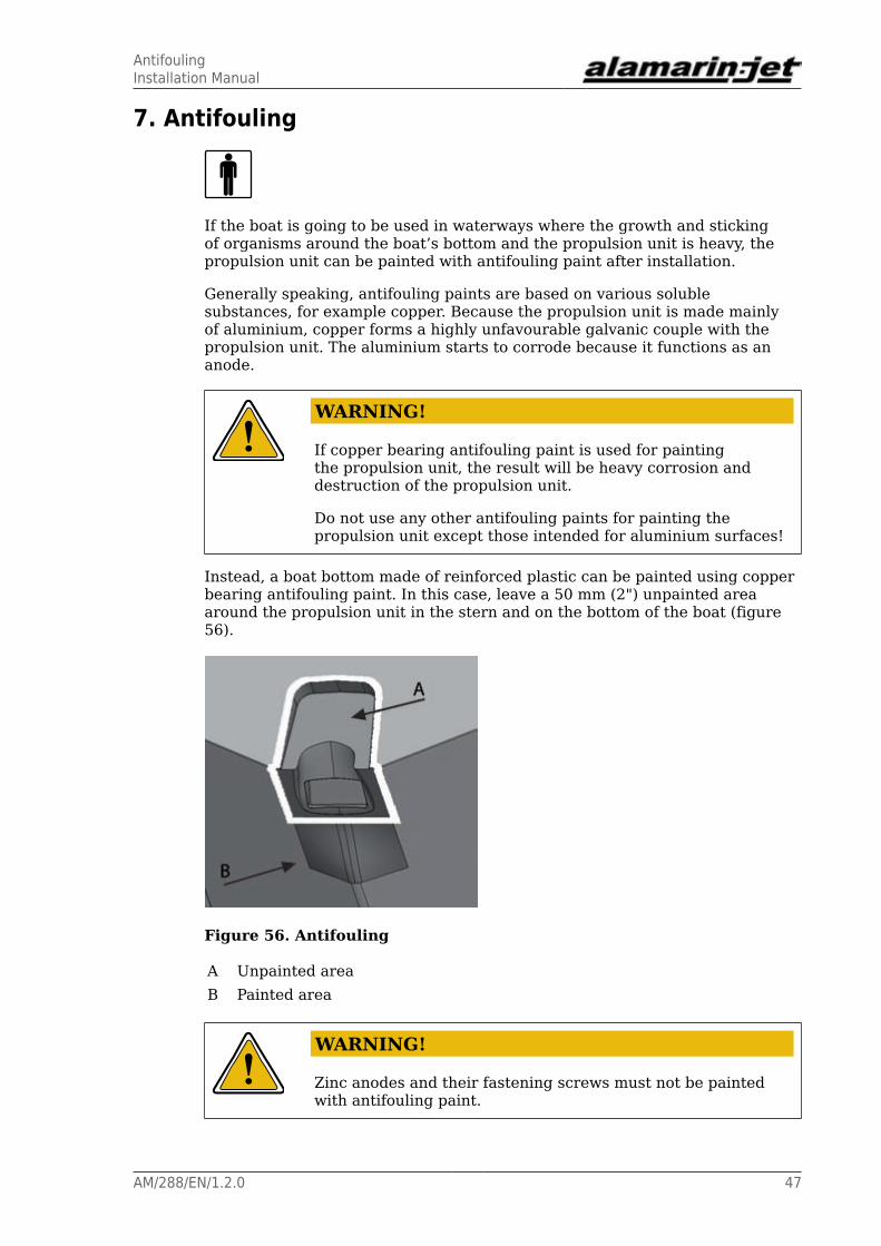
Instead, a boat bottom made of reinforced plastic can be painted using copperbearing antifouling paint. In this case, leave a 50 mm (2") unpainted areaaround the propulsion unit in the stern and on the bottom of the boat (figure56).
Figure 56. Antifouling
A Unpainted areaB Painted area
WARNING!
Zinc anodes and their fastening screws must not be paintedwith antifouling paint.

AntifoulingInstallation Manual
48 AM/288/EN/1.2.0

Grease recommendationsInstallation Manual
AM/288/EN/1.2.0 49
Appendix 1. Grease recommendationsThe grease used for lubricating the propulsion unit bearing must meet thefollowing requirements:
• lithium soap and a thickener with EP additives
• mineral oil as a base oil
• NLGI class 2
• operating temperature range -25 to 130°C (-13–266 °F)
• continuous operating temperature min. 75 °C (167 °F)
Recommended grease brands:
• Würth Multi-Purpose Grease III
• FAG Multi2
• FAG Load 220
• Mobil XHP 222
• Neste Allrex EP2
• Shell Retinax Grease EP2
A grease that has equivalent properties to those mentioned above can also beused for lubrication.
Oil recommendationsInstallation Manual
50 AM/288/EN/1.2.0
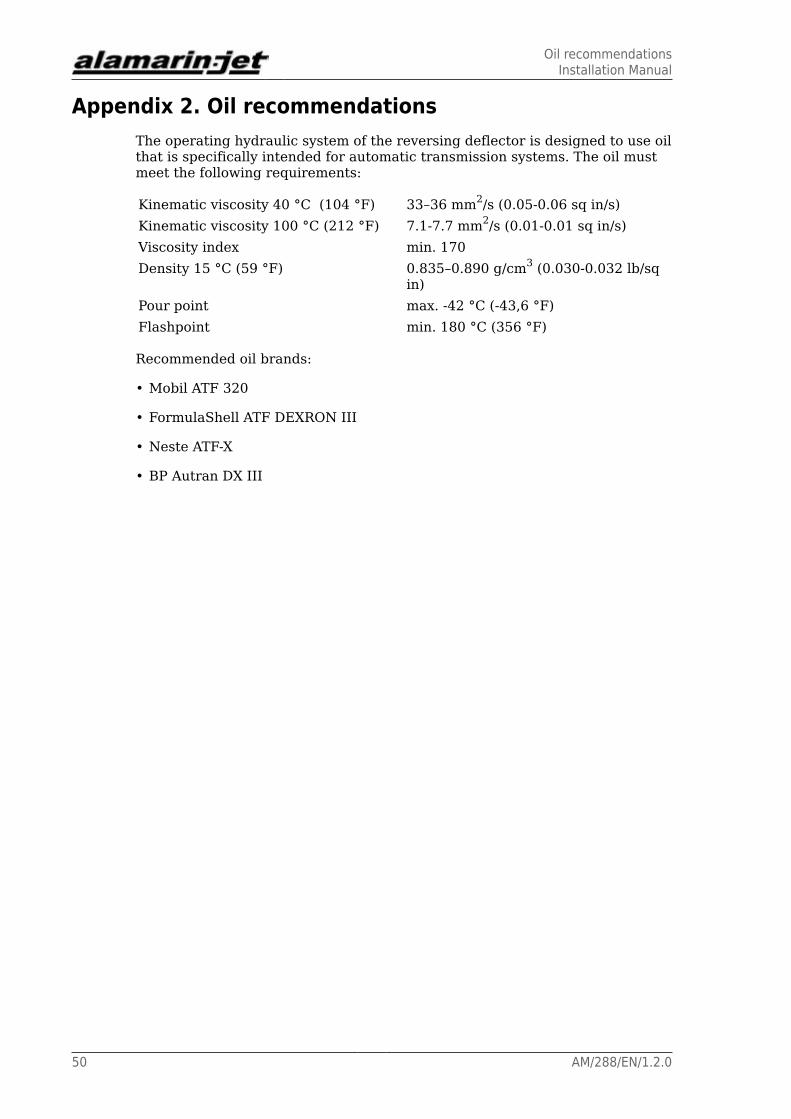
Appendix 2. Oil recommendationsThe operating hydraulic system of the reversing deflector is designed to use oilthat is specifically intended for automatic transmission systems. The oil mustmeet the following requirements:
Kinematic viscosity 40 °C (104 °F) 33–36 mm2/s (0.05-0.06 sq in/s)Kinematic viscosity 100 °C (212 °F) 7.1-7.7 mm2/s (0.01-0.01 sq in/s)Viscosity index min. 170Density 15 °C (59 °F) 0.835–0.890 g/cm3 (0.030-0.032 lb/sq
in)Pour point max. -42 °C (-43,6 °F)Flashpoint min. 180 °C (356 °F)
Recommended oil brands:
• Mobil ATF 320
• FormulaShell ATF DEXRON III
• Neste ATF-X
• BP Autran DX III

Tightening torquesInstallation Manual
AM/288/EN/1.2.0 51
Appendix 3. Tightening torquesUse the tightening torques from the table 2 when tightening the propulsionunit screws. The strength grade of an acid-proof A4-80 screw is equivalent to aclass 8.8 screw.
Table 2. Tightening torques of the screws
Strength grade 8.8 10.9 12.9Thread Tightening torque
(Nm) (*)
M5 5.5 (4) 8.1 (6) 9.5 (7)M6 9.6 (7) 14 (10) 16 (12)M8 23 (17) 34 (25) 40 (30)M10 46 (34) 67 (49) 79 (58)M12 79 (58) 115 (85) 135 (100)M16 145 (107) 215 (159) 250 (184)
(*) The tightening torque in pound-feet (approximate value) is marked in thetable in parentheses after the corresponding value in Nm.
A suitable thread locking compound that is good for all purposes is one ofmedium strength, for example. Loctite 242 or similar.

Mounting templateInstallation Manual
52 AM/288/EN/1.2.0
Appendix 4. Mounting template

Change in the v angleInstallation Manual
AM/288/EN/1.2.0 53
Appendix 5. Change in the v angle
Figure 57. Change in the v angle
O Degree of the v angleL Measurement in millimetres (1 mm = approx. 0.04")

Connecting rod for double installationInstallation Manual
54 AM/288/EN/1.2.0
Appendix 6. Connecting rod for double installation
*) Measure x is determined by the distance between the jets.**) Welding method TIG.
Materials to be welded EN 1.4436.
Control systemsInstallation Manual
AM/288/EN/1.2.0 55
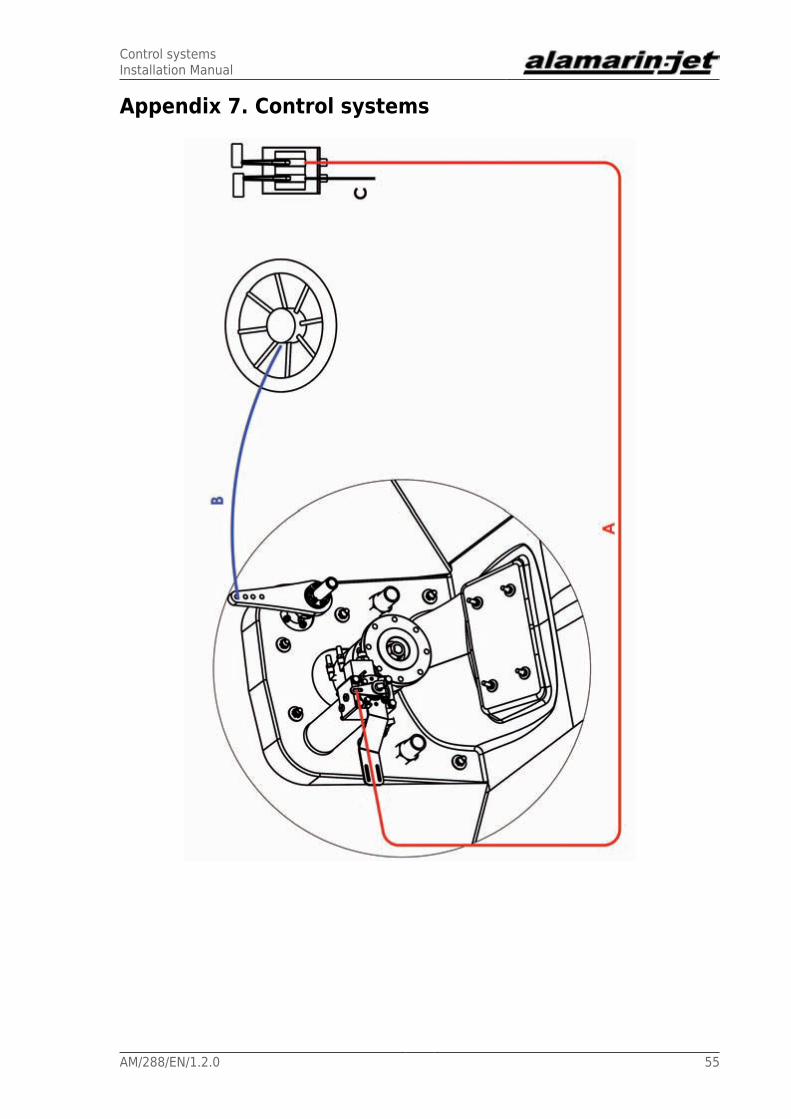
Appendix 7. Control systems

Control systemsInstallation Manual
56 AM/288/EN/1.2.0
A Reversing deflector's control cableB Steering device (cable or hydraulic)C Accelerator and gearbox control cablesD Connecting rod for double installation

Lever movement rangesInstallation Manual
AM/288/EN/1.2.0 57
Appendix 8. Lever movement rangesSteering lever
The maximum rotating angle for the lever is 25°. The steering device'smaximum stroke length is 152 mm (5.9"). If the steering device's stroke islonger than this, it must be limited or the system may be damaged.
Lever holing may vary. Please contact the manfacturer if you need moredetailed information.

Lever movement rangesInstallation Manual
58 AM/288/EN/1.2.0
Hydraulic cylinder control lever
The length of a full stroke in point A is approx. 64 mm (2.5").
The length of a full stroke in point B is approx. 46 mm (1.8").