Installation Manual AIR-TO-WATER HEATPUMP MONO BLOC WH ... · WH-MDC05H3E5, WH-MDC07H3E5,...
1
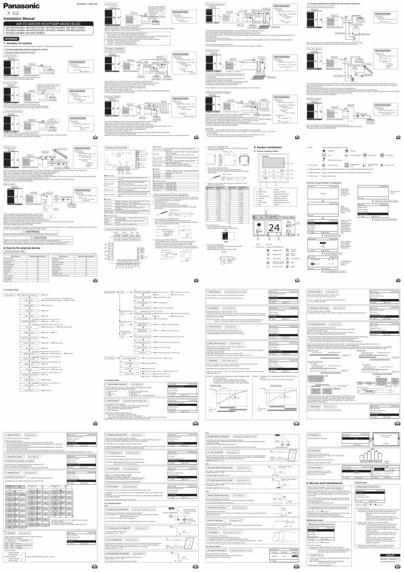
Installation Manual AIR-TO-WATER HEATPUMP MONO BLOC WH-MDC05H3E5, WH-MDC07H3E5, WH-MDC09H3E5, WH-MDC12H6E5, WH-MDC16H6E5, WH-MXC09H3E5, WH-MXC12H6E5, WH-MXC09H3E8, WH-MXC12H9E8, WH-MXC16H9E8 ACXF60-17020-AA APPENDIX This section introduces variation of various systems using Air-To-Water Heatpump and actual setting method. 1-1 Introduce application related to temperature setting. Temperature setting variation for heating 1. Remote Controller Mono bloc Floor heating Mono bloc or Connect floor heating or radiator directly to the Mono bloc. This is the basic form of the most simple system. 2. Room Thermostat Mono bloc Mono bloc receive Room Thermo signal (ON/OFF) from Remote controller to control HP and circulation pump. There is a build-in thermistor in the remote controller. Floor heating Mono bloc or Connect floor heating or radiator directly to the Mono bloc. Install the remote controller in the room where floor heating is installed. This is an application that uses remote controller as Room Thermostat. 3. External Room Thermostat Mono bloc Room thermostat (Field supply) Floor heating Mono bloc or Connect floor heating or radiator directly to Mono bloc. Install separate external Room Thermostat (field supply) in the room where floor heating is installed. This is an application that uses external Room Thermostat. 1 Variation of system Setting of remote controller Installer setting System setup Optional PCB connectivity - No Zone & Sensor: Water temperature Setting of remote controller Installer setting System setup Optional PCB connectivity - No Zone & Sensor: Room thermostat Internal Setting of remote controller Installer setting System setup Optional PCB connectivity - No Zone & Sensor: Room thermostat (External) 1 4. Room Thermistor or Mono bloc Max: 30m Thermistor Mono bloc compare between room temperature and setting temperature on the Remote controller to control HP and circulation pump. Floor heating Mono bloc Connect floor heating or radiator directly to Mono bloc. Install separate external room thermistor (specified by Panasonic) in the room where floor heating is installed. This is an application that uses external room thermistor. There are 2 kinds of circulation water temperature setting method. Direct: set direct circulation water temperature (fixed value) Compensation curve: set circulation water temperature depends on outdoor ambient temperature In case of Room thermo or Room thermistor, compensation curve can be set. In this case, compensation curve is shifted according to the thermo ON/OFF situation. • (Example) If room temperature increasing speed is; very slow shift up the compensation curve very fast shift down the compensation curve Examples of installations Floor heating 1 + Floor heating 2 or Mono bloc Room thermostat (field supply) Thermistor 2 Thermistor 1 Buffer tank Pump 2 Pump 1 Mixing valve 2 Mixing valve 1 Mono bloc Floor heating 2 Floor heating 1 Connect floor heating to 2 circuits through buffer tank as shown in the figure. Install mixing valves, pumps and thermistors (specified by Panasonic) on both circuits. Install the remote controller in one of the circuit and use it as Room Thermostat. Install external Room Thermostat (field supply) in another circuit. Both circuits can set circulation water temperature independently. Install buffer tank thermistor on buffer tank. It requires connection setting of buffer tank and T temperature setting at heating operation separately. This system requires optional PCB (CZ-NS4P). Floor heating + Radiator Mono bloc Radiator Thermistor 1 Thermistor 2 Buffer tank Pump 2 Pump 1 Mixing valve 1 Mono bloc Floor heating or Connect floor heating or radiator to 2 circuits through buffer tank as shown in figure. Install pumps and thermistors (specified by Panasonic) on both circuits. Install mixing valve in the circuit with lower temperature among the 2 circuits. (Generally, if install floor heating and radiator circuit at 2 zones, install mixing valve in floor heating circuit.) For temperature setting, select circulation water temperature for both circuits. Both circuits can set circulation water temperature independently. Install buffer tank thermistor on buffer tank. It requires connection setting of buffer tank and T temperature setting at heating operation separately. This system requires the optional PCB (CZ-NS4P). Mind that if there is no mixing valve at the secondary side, the circulation water temperature may get higher than setting temperature. Setting of remote controller Installer setting System setup Optional PCB connectivity - No Zone & Sensor: Room thermistor Setting of remote controller Installer setting System setup Optional PCB connectivity - Yes Zone and Sensor - 2 Zone system Zone 1:Sensor Room thermostat Internal Zone 2:Sensor Room Room thermostat (External) Setting of remote controller Installer setting System setup Optional PCB connectivity - Yes Zone and Sensor - 2 Zone system Zone 1:Sensor Water temperature Zone 2:Sensor Room Water temperature 2 Floor heating + Swimming pool Mono bloc Thermistor 1 Heat EXT Thermistor 3 Thermistor 2 Buffer tank Pump 2 Pump 3 Pump 1 Mixing valve 1 Mixing valve 2 Mono bloc Floor heating 1 Swimming pool or Connect floor heating and swimming pool to 2 circuits through buffer tank as shown in figure. Install mixing valves, pumps and thermistors (specified by Panasonic) on both circuits. Then, install additional pool heat exchanger, pool pump and pool sensor on pool circuit. Install the remote controller in room where floor heating is installed. Circulation water temperature of floor heating and swimming pool can be set independently. Install buffer tank sensor on buffer tank. It requires connection setting of buffer tank and T temperature setting at heating operation separately. This system requires the optional PCB (CZ-NS4P). Must connect swimming pool to “Zone 2”. If it is connected to swimming pool, operation of pool will stop when “Cooling” is operated. Swimming pool only Thermistor Pump Swimming pool Heat EXT This is an application that connects to the swimming pool only. Connects pool heat exchanger directly to Mono bloc without using buffer tank. Install pool pump and pool sensor (specified by Panasonic) at secondary side of the pool heat exchanger. Install the remote controller in room where floor heating is installed. Temperature of swimming pool can be set independently. This system requires the optional PCB (CZ-NS4P). In this application, cooling mode cannot be selected. (not display on remote controller) Mono bloc Mono bloc or Simple 2 zone (Floor heating + Radiator) This is an example of simple 2 zone control without using buffer tank. Built-in pump from Mono bloc served as a pump in zone 1. Install mixing valve, pump and thermistor (specified by Panasonic) on zone 2 circuit. Please be sure to assign high temperature side to zone 1 as temperature of zone 1 cannot be adjusted. Zone 1 thermistor is required to display temperature of zone 1 on remote controller. Circulation water temperature of both circuits can be set independently. (However, temperature of high temperature side and low temperature side cannot be reversed) This system requires the optional PCB (CZ-NS4P). (CAUTION) • Thermistor 1 does not affect operation directly. But error happens if it is not installed. • Please adjust flow rate of zone 1 and zone 2 to be in balance. If it is not adjusted correctly, it may affects the performance. (If zone 2 pump flow rate is too high, there is possibility that no hot water flowing to zone 1.) Flow rate can be confirmed by “Actuator Check” from maintenance menu. Floor heating Thermistor 2 Thermistor 1 Pump 2 Mixing valve Mono bloc Mono bloc Radiator or Setting of remote controller Installer setting System setup Optional PCB connectivity - Yes Zone and Sensor - 2 Zone system Zone 1:Sensor Room thermostat Internal Zone 2 Swimming pool T Setting of remote controller Installer setting System setup Optional PCB connectivity - Yes Zone and Sensor - 1 Zone system Zone :Swimming pool T Setting of remote controller Installer setting System setup Optional PCB connectivity - Yes Zone and Sensor - 2 Zone system Zone 1:Sensor Water temperature Zone 2:Sensor Room Water temperature Operation setup Heat T for heating ON – 1°C Cool T for cooling ON – 1°C 3 1-2. Introduce applications of system that uses optional equipment. DHW (Domestic Hot Water) Tank connection Mono bloc Tank Tank thermistor 3-way valve for tank Booster heater Mono bloc Floor heating or This is an application that connects the DHW tank to the Mono bloc through 3-way valve. DHW tank’s temperature is detected by tank thermistor (specified by Panasonic). Tank + Solar connection Mono bloc Tank Tank thermistor 3-way valve for tank Solar pump Floor heating Solar thermistor or Mono bloc This is an application that connects the DHW tank to the Mono bloc through 3-way valve before connect the solar water heater to heat up the tank. DHW tank’s temperature is detected by tank thermistor (specified by Panasonic). Solar panel’s temperature is detected by solar thermistor (specified by Panasonic). DHW tank shall use tank with built-in solar heat exchange coil independently. Heat accumulation operates automatically by comparing the temperature of tank thermistor and solar thermistor. During winter season, solar pump for circuit protection will be activated continuously. If does not want to activate the solar pump operation, please use glycol and set the anti-freezing operation start temperature to -20°C. This system requires optional PCB (CZ-NS4P). Buffer tank connection or Mono bloc Thermistor Buffer tank Pump Mono bloc Floor heating This is an application that connects the buffer tank to the Mono bloc. Buffer tank’s temperature is detected by buffer tank thermistor (specified by Panasonic). This system requires optional PCB (CZ-NS4P). Setting of remote controller Installer setting System setup Optional PCB connectivity - Yes Tank connection - Yes Solar connection - Yes DHW tank T turn ON T turn OFF Antifreeze Hi limit Setting of remote controller Installer setting System setup Optional PCB connectivity - Yes Buffer Tank connection - Yes T for buffer tank Setting of remote controller Installer setting System setup Optional PCB connectivity - No Tank connection - Yes 4 Buffer tank + Solar This is an application that connects the buffer tank to the Mono bloc before connecting to the solar water heater to heat up the tank. Buffer tank’s temperature is detected by buffer tank thermistor (specified by Panasonic). Solar panel’s temperature is detected by solar thermistor (specified by Panasonic). Buffer tank shall use tank with built-in solar heat exchange coil independently. During winter season, solar pump for circuit protection will be activated continuously. If does not want to activate the solar pump operation, please use glycol and set the anti-freezing operation start temperature to -20°C. Heat accumulation operates automatically by comparing the temperature of tank thermistor and solar thermistor. This system requires optional PCB (CZ-NS4P). Boiler connection or Thermistor Boiler Mixing valve Floor heating Pump Buffer tank Mono bloc Mono bloc Setting of remote controller Installer setting System setup Optional PCB connectivity - Yes Buffer Tank connection - Yes T for buffer tank Solar connection - Yes Buffer tank T turn ON T turn OFF Antifreeze Hi limit Setting of remote controller Installer setting System setup Optional PCB connectivity - Yes Bivalent - Yes Turn ON: outdoor temp Control pattern 2 How to x external device Connecting Cables Length When connecting cables between Mono bloc and external devices, the length of the said cables must not exceed the maximum length as shown in the table. External device Maximum cables length (m) External device Maximum cables length (m) Two-way valve 50 Outdoor air sensor 30 Three-way valve 50 Tank OLP 30 Mixing valve 50 Buffer tank sensor 30 Room thermostat 50 Pool water sensor 30 Booster heater 50 Solar sensor 30 Extra pump 50 Water sensor 30 Solar pump 50 Demand signal 50 Pool pump 50 SG signal 50 Pump 50 Heat/Cool switch 50 Boiler contact 50 External compressor switch 50 External control 50 Tank sensor 30 Room sensor 30 This is an application that connects the boiler to the Mono bloc, to compensate for insufficient capacity by operate boiler when outdoor temperature drops & heat pump capacity is insufficient. Boiler is connected parallel with heat pump against heating circuit. There are 3 modes selectable by remote controller for boiler connection. Besides that, an application that connects to the DHW tank’s circuit to heat up tank’s hot water is also possible. (Operation setting of boiler shall be responsible by installer.) This system requires optional PCB (CZ-NS4P). Depending on the settings of the boiler, it is recommended to install buffer tank as temperature of circulating water may get higher. (It must connect to buffer tank especially when selecting Advanced Parallel setting.) WARNING Panasonic is NOT responsible for incorrect or unsafe situation of the boiler system. CAUTION Make sure the boiler and its integration in the system complies with applicable legislation. Make sure the return water temperature from the heating circuit to the Mono bloc does NOT exceed 55°C. Boiler is turned off by safety control when the water temperature of the heating circuit exceed 85°C. Solar thermistor Thermistor Solar pump Mixing valve Floor heating Pump Buffer tank Mono bloc Mono bloc or 5 Connection of the main PCB OLP for booster heater Zone 1 room sensor Outdoor air sensor Tank sensor External control Remote controller Boiler contact Extra pump Booster heater H C N L C O N C O N Optional Thermostat 1 3-way valve 2-way valve Signal inputs Optional Thermostat L N =AC230V, Heat, Cool=Thermostat heat, Cool terminal It does not function when using the optional PCB OLP for booster heater Dry contact Vcc-Bit1, Vcc-Bit2 open/short (System setup necessary) It is connected to the safety device (OLP) of DHW tank. External control Dry contact Open=not operate, Short=operate (System setup necessary) Able to turn ON/OFF the operation by external switch Remote controller Connected (Please use 2 cores wire for relocation and extension. Total cable length shall be 50m or less.) Outputs 3-way valve AC230V N=Neutral Open, Close=direction (For circuit switching when connected to DHW tank) 2-way valve AC230V N=Neutral Open, Close (Prevent water circuit pass through during cooling mode) Extra pump AC230V (Used when Mono bloc pump capacity is insufficient) Booster heater AC230V (Used when using booster heater in DHW tank) Boiler contact Dry contact (System setup necessary) Thermistor inputs Zone 1 room sensor PAW-A2W-TSRT It does not work when using the optional PCB Outdoor air sensor AW-A2W-TSOD (Total cable length shall be 30m or less) Tank sensor Please use Panasonic specified part Connection of Optional PCB (CZ-NS4P) Ext. comp. SW Heat/ Cool SW SG signal Vcc Bit1 Bit2 Solar sensor Mixing valve 2 Mixing valve 1 Optional Thermostat 2 Optional Thermostat 1 Demand signal Zone 1 water sensor Zone 2 water sensor Pool water sensor Buffer Tank sensor Zone 1 room sensor Zone 2 room sensor Zone 1 Pump Error signal Pool Pump Solar Pump Zone 2 Pump N O C N O C L N Cool Heat L N Cool Heat Signal inputs Optional Thermostat L N =AC230V, Heat, Cool=Thermostat heat, Cool terminal SG signal Dry contact Vcc-Bit1, Vcc-Bit2 open/short (System setup necessary) Switching SW (Please connect to the 2 contacts controller) Heat/Cool SW Dry contact Open=Heat, Short=Cool (System setup necessary) External comp.SW Dry contact Open=Comp.ON, Short=Comp.OFF (System setup necessary) Demand signal DC 0~10V (System setup necessary) Please connect to the DC 0~10V controller. Outputs Mixing valve AC230V N=Neutral Open, Close=mixture direction Operating time: 30s~120s Pool pump AC230V Solar pump AC230V Zone pump AC230V Thermistor inputs Zone room sensor PAW-A2W-TSRT Buffer tank sensor PAW-A2W-TSBU Pool water sensor PAW-A2W-TSHC Zone water sensor PAW-A2W-TSHC Solar sensor PAW-A2W-TSSO Recommended External Device Specification • This section explains about the external devices (optional) recommended by Panasonic. Please always ensure to use the correct external device during system installation. • For optional sensor. 1. Buffer tank sensor: PAW-A2W-TSBU Use for measurement of the buffer tank temperature. Insert the sensor into the sensor pocket and paste it on the buffer tank surface. 40 black brown blue Dimensions (mm) Ø6 2. Zone water sensor: PAW-A2W-TSHC Use to detect the water temperature of the control zone. Mount it on the water piping by using the stainless steel metal strap and contact paste (both are included). 93 70 35 Dimensions (mm) 3. Outdoor sensor: PAW-A2W-TSOD If the installation location of the outdoor unit is exposed to direct sunlight, the outdoor air temperature sensor will be unable to measure the actual outdoor ambient temperature correctly. In this case, optional outdoor temperature sensor can be fixed at a suitable location to more accurately measure ambient temperature. 70 93 46 Dimensions (mm) 6 4. Room sensor: PAW-A2W-TSRT Install the room temperature sensor to the room which requires room temperature control. Dimensions (mm) 86 86 60 30 5. Solar sensor: PAW-A2W-TSSO Use for measurement of the solar panel temperature. Insert the sensor into the sensor pocket and paste it on the solar panel surface. 40 black brown blue Dimensions (mm) Ø6 6. Please refer to the table below for sensor characteristic of the sensors mentioned above. Temperature (°C) Resistance (kΩ) Temperature (°C) Resistance (kΩ) 30 5.326 150 0.147 25 6.523 140 0.186 20 8.044 130 0.236 15 9.980 120 0.302 10 12.443 110 0.390 5 15.604 100 0.511 0 19.70 90 0.686 -5 25.05 80 0.932 -10 32.10 70 1.279 -15 41.45 65 1.504 -20 53.92 60 1.777 -25 70.53 55 2.106 -30 93.05 50 2.508 -35 124.24 45 3.003 -40 167.82 40 3.615 35 4.375 • For optional pump. Power supply: AC230V/50Hz, <500W Recommended part: Yonos 25/6: made by Wilo • For optional mixing valve. Power supply: AC230V/50Hz (input open/output close) Operating time: 30s~120s Recommended part: 167032: made by Caleffi 3-1. Remote Controller Outline A B C D G F E Name Function A: Main screen Display information B: Menu Open/Close main menu C: Triangle (Move) Select or change item D: Operate Start/Stop operation E: Back Back to previous item F: Quick Menu Open/Close Quick menu G: OK Confirm 3 System installation Name Function 1: Function icon Display set function/status Holiday mode Demand control Weekly timer Room heater Quiet mode Tank heater Remote controller room thermostat Solar Powerful mode Boiler 24 40˚c 10:34am, Mon 18˚c 5 6 4 3 2 1 ˚c 12:00am,Mon 7 2: Mode Display set mode/current status of mode Heating Cooling Auto Hot water supply Auto heating Auto cooling Heat pump operating 3: Temp setting Set room temp Compensation curve Set direct water temp Set pool temp 4: Display Heat temp Display current heating temperature (it is set temperature when enclosed by line) 5: Display tank temp Display current tank temperature (it is set temperature when enclosed by line) 6: Outdoor temp Display outdoor temp First time of power ON (Start of installation) Initialization 12:00am,Mon Initializing. When power is ON, firstly initialization screen appears (10 sec) « 12:00am,Mon Start When initialization screen ends, it turns to normal screen. « Language 12:00am,Mon ENGLISH FRANÇAIS DEUTSCH ITALIANO Select Confirm When any button is pressed, language setting screen appears. (CAUTION) If initial setting is not performed, it does not go into menu. « Set language & confirm Clock format 12:00am,Mon 24h am/pm Select Confirm When language is set, setting screen of time display appears (24h/am/pm) « Set time display & confirm Date & time 12:00am,Mon Year/Month/Day Hour : Min 2015 / 01 / 01 12 : 00 Select Confirm YY/MM/DD/Time setup screen appears « Set YY/MM/DD/Time & confirm 12:00am,Mon Start Back to initial screen « Press menu, select Installer setup Main Menu 12:00am,Mon System check Personal setup Service contact Installer setup Select Confirm « Confirm to go into Installer setup 8 3-2. Installer Setup 1 System setup Optional PCB connectivity Yes/No 2 Only when the selection for optional PCB is Yes Zone & Sensor 1 Zone system/2 Zone system Zone settings 3 Heater capacity Capacity select 4 Anti freezing Yes/No 5 Tank connection Yes/No 6 Only when the selection for optional PCB is Yes Buffer Tank connection Yes/No T setup 7 Only when the selection for Tank connection is Yes Tank heater External/Internal Heater ON time setup 8 Base pan heater Yes/No A / B 9 Alternative outdoor sensor Yes/No 10 Bivalent connection Yes/No Bivalent setup 11 External SW Yes/No 12 Only when the selection for optional PCB is Yes Solar connection Yes/No Tank setup Solar setup 13 Only when the selection for optional PCB is Yes External Error signal Yes/No 14 Only when the selection for optional PCB is Yes Demand control Yes/No 15 Only when the selection for optional PCB is Yes SG ready Yes/No Capacity setup 16 Only when the selection for optional PCB is Yes External Compressor SW Yes/No 17 Circulation liquid Water/glycol 18 Only when the selection for optional PCB is Yes Heat-Cool SW Yes/No 19 Force Heater Auto/Manual 9 20 Operation setup Heat Water temp. for heating ON Compensation curve Compensation curve setup Cooling model only 21 Direct Direct temp. setup Outdoor temp. for heating OFF Heating OFF Temp. setup 22 T for heating ON T for heating setup 23 Outdoor temp. for heater ON O/D temp for heater ON setup 24 (Display only if Cool exist, or else skip) Cool Water temp. for cooling ON Compensation curve Compensation curve setup Cooling model only 25 Direct Direct temp. setup T for Cooling ON T for cooling setup 26 Auto Outdoor temp. for (Heat to Cool) Heat Cool change temp. setup 27 Outdoor temp. for (Cool to Heat) Cool Heat change temp. setup 28 Tank Floor operation time (max.) Max. operation time for Heat & Cool mode setup 29 Tank heat up time (max.) Max. operation time for Tank mode setup 30 Tank re-heat temp. Tank re-heat temp. setup 31 Sterilization Sterilization day and temp. and time setup 32 Service setup Pump maximum speed Pump maximum speed setup Air purge 33 Pump down Pump down ON/OFF 34 Dry concrete ON (Dry concrete) 35 Edit (Dry concrete schedule) Day and temp. setup Service contact Contact 1 Name and Tel No. setup Contact 2 Name and Tel No. setup Only when the selection for Tank is Yes 3-3. System Setup 1. Optional PCB connectivity Initial setting: No System setup 12:00am,Mon Optional PCB connectivity Zone & Sensor Heater capacity Anti freezing Select Confirm If function below is necessary, please purchase and install optional PCB. Please select Yes after installing optional PCB. • 2-zone control • Pool • Buffer tank • Solar • External error signal output • Demand control • SG ready • Stop heat source unit by external SW 2. Zone & Sensor Initial setting: Room and Water temp. System setup 12:00am,Mon Optional PCB connectivity Zone & Sensor Heater capacity Anti freezing Select Confirm If no Optional PCB connectivity Select sensor of room temperature control from the following 3 items 1Water temperature (Circulation water temperature) 2Room thermostat (Internal or External) 3Room thermistor When there is Optional PCB connectivity 1Select either 1 zone control or 2 zone control. If it is 1 zone, select either room or pool, select sensor If it is 2 zone, after select sensor of zone 1, select either room or pool for zone 2, select sensor (CAUTION) In 2 zone system, pool function can be set at zone 2 only. 10 3. Heater capacity Initial setting: Depend on model System setup 12:00am,Mon Optional PCB connectivity Zone & Sensor Heater capacity Anti freezing Select Confirm If there is built-in Heater, set the selectable heater capacity. (CAUTION) There are models which cannot select heater. 4. Anti freezing Initial setting: Yes System setup 12:00am,Mon Optional PCB connectivity Zone & Sensor Heater capacity Anti freezing Select Confirm Operate anti-freezing of water circulation circuit. If select Yes, when the water temperature is reaching its freezing temperature, the circulation pump will start up. If the water temperature does not reach the pump stop temperature, back- up heater will be activated. (CAUTION) If set No, when the water temperature is reaching its freezing temperature or below 0°C, the water circulation circuit may freeze and cause malfunction. 5. Tank connection Initial setting: No System setup 12:00am,Mon Zone & Sensor Heater capacity Anti freezing Tank connection Select Confirm Select whether it is connected to hot water tank or not. If set Yes, it becomes setting that uses hot water function. Hot water temperature of tank can be set from main screen. 6. Buffer Tank connection Initial setting: No System setup 12:00am,Mon Heater capacity Anti freezing Tank connection Buffer tank connection Select Confirm Select whether it is connected to buffer tank for heating or not. If buffer tank is used, please set Yes. Connect buffer tank thermistor and set, T ( T use to increase primary side temp against secondary side target temp). (CAUTION) Does not display if there is no Optional PCB. If the buffer tank capacity is not so large, please set larger value for T. 7. Tank heater Initial setting: Internal System setup 12:00am,Mon Anti freezing Tank connection Buffer tank connection Tank heater Select Confirm Select to use either built-in heater or external heater as heater for hot water tank. If heater is installed on tank, please select External. (CAUTION) Does not display if there is no tank for hot water supply. Please set “Tank heater” to “ON” in the “Function setup” from remote controller when using heater to boil the tank. External A setting which is using booster heater installed on DHW tank to boil the tank. The permissible heater capacity is 3kW and below. The operation to boil the tank with heater is as below. In addition, be sure to set suitable “Tank heater: ON time” Internal A setting which is using backup heater of Mono bloc to boil the tank. The operation to boil the tank with heater is as below. 65 53 HP thermo OFF HP Booster heater Tank temp. ON time Pump For 65°C setting 65 53 HP thermo OFF HP Backup heater Tank temp. A Pump For 65°C setting 11 8. Base pan heater Initial setting: No System setup 12:00am,Mon Tank connection Buffer tank connection Tank heater Base pan heater Select Confirm Select whether Base pan heater is installed or not. If set Yes, select to use either heater A or B. A: Turn on Heater when heating with defrost operation only B: Turn on Heater at heating 9. Alternative outdoor sensor Initial setting: No System setup 12:00am,Mon Buffer tank connection Tank heater Base pan heater Alternative outdoor sensor Select Confirm Set Yes if outdoor sensor is installed. Controlled by optional outdoor sensor without reading the outdoor sensor of heat pump unit. 10. Bivalent connection Initial setting: No System setup 12:00am,Mon Tank heater Base pan heater Alternative outdoor sensor Bivalent connection Select Confirm Set if heat pump linked with boiler operation. Connect the start signal of the boiler in boiler contact terminal (main PCB). Set Bivalent connection to YES. After that, please begin setting according to remote controller instruction. Boiler icon will be displayed on remote controller top screen. There are 3 different modes in the boiler operation. Movement of each modes are shown below. 1Alternative (switch to boiler operation when drops below setting temperature) 2Parallel (allow boiler operation when drops below setting temperature) 3Advanced Parallel (able to slightly delay boiler operation time of parallel operation) When the boiler operation is “ON”, “boiler contact” is “ON”, “_”(underscore) will be displayed below the boiler icon. Please set target temperature of boiler to be the same as heat pump temperature. When boiler temperature is higher than heat pump temperature, zone temperature cannot be achieved if mixing valve is not installed. This product only allows one signal to control the boiler operation. Operation setting of boiler shall be responsible by installer. operate heat pump only -10°C (setting from remote controller) operate boiler only Alternative mode Outdoor temp. operate heat pump only -10°C (setting from remote controller) operate boiler and heat pump simultaneously Parallel mode Outdoor temp. operate heat pump only -10°C (setting from remote controller) operate boiler and heat pump simultaneously For heating Outdoor temp. Advanced Parallel mode AND Circulation water temp. Setting temp Boiler temp. OFF = Setting -2°C (setting from remote controller) Boiler temp. ON = Setting -8°C (setting from remote controller) Although heat pump operates but water temperature does not reach this temperature for more than 30 mins (setting from remote controller) operate heat pump only -10°C (setting from remote controller) operate boiler and heat pump simultaneously For DHW tank Outdoor temp. AND time Tank setting temp. 30 min (setting from remote control) If actual tank temp. does not achieve the setting temp. within 30min (setting from remote controller), the boiler turn ON When tank temp. is achieved, both operations stop Heat pump thermo ON Tank temp. Lowering Tank temp. Boiling initial temp. Heat pump Boiler In Advanced Parallel mode, setting for both heating and tank can be made simultaneously. During operation of “Heating/Tank” mode, when each time the mode is switched, the boiler output will be reset to OFF. Please have good understanding on the boiler control characteristic in order to select the optimal setting for the system. 11. External SW Initial setting: No System setup 12:00am,Mon Base pan heater Alternative outdoor sensor Bivalent connection External SW Select Confirm Able to turn ON/OFF the operation by external switch. 12 12. Solar connection Initial setting: No System setup 12:00am,Mon Alternative outdoor sensor Bivalent connection External SW Solar connection Select Confirm Set when solar water heater is installed. Setting include items below. 1Set either buffer tank or DHW tank for connection with solar water heater. 2Set temperature difference between solar panel thermistor and buffer tank or DHW tank thermistor to operate the solar pump. 3Set temperature difference between solar panel thermistor and buffer tank or DHW tank thermistor to stop the solar pump. 4Anti-freezing operation start temperature (please change setting based on usage of glycol.) 5Solar pump stop operation when it exceeds high limit temperature (when tank temperature exceed designated temperature (70~90°C)) 13. External Error signal Initial setting: No System setup 12:00am,Mon Bivalent connection External SW Solar connection External Error signal Select Confirm Set when external error display unit is installed. Turn on Dry Contact SW when error happened. (CAUTION) Does not display when there is no Optional PCB. When error occurs, error signal will be ON. After turn off “close” from the display, error signal will still remain ON. 14. Demand control Initial setting: No System setup 12:00am,Mon External SW Solar connection External Error signal Demand control Select Confirm Set when there is demand control. Adjust terminal voltage within 1 ~ 10 V to change the operating current limit. (CAUTION) Does not display when there is no Optional PCB. Analog input [v] Rate [%] Analog input [v] Rate [%] Analog input [v] Rate [%] 0.0 not activate 3.9 ~ 4.1 40 7.4 ~ 7.6 75 0.1 ~ 0.6 4.2 45 40 7.7 80 75 0.7 10 not activate 4.3 7.8 0.8 4.4 ~ 4.6 45 7.9 ~ 8.1 80 0.9 ~ 1.1 10 4.7 50 45 8.2 85 80 1.2 15 10 4.8 8.3 1.3 4.9 ~ 5.1 50 8.4 ~ 8.6 85 1.4 ~ 1.6 15 5.2 55 50 8.7 90 85 1.7 20 15 5.3 8.8 1.8 5.4 ~ 5.6 55 8.9 ~ 9.1 90 1.9 ~ 2.1 20 5.7 60 55 9.2 95 90 2.2 25 20 5.8 9.3 2.3 5.9 ~ 6.1 60 9.4 ~ 9.6 95 2.4 ~ 2.6 25 6.2 65 60 9.7 100 95 2.7 30 25 6.3 9.8 2.8 6.4 ~ 6.6 65 9.9 ~ 100 2.9 ~ 3.1 30 6.7 70 65 *A minimum operating current is applied on each model for protection purpose. *0.2 voltage hysteresis is provided. *The value of voltage after 2nd decimal point are cut off. 3.2 35 30 6.8 3.3 6.9 ~ 7.1 70 3.4 ~ 3.6 35 7.2 75 70 3.7 40 35 7.3 3.8 15. SG ready Initial setting: No System setup 12:00am,Mon Solar connection External Error signal Demand control SG ready Select Confirm Switch operation of heat pump by open-short of 2 terminals. Setting belows are possible SG signal Working pattern Vcc-bit1 Vcc-bit2 Open Open Normal Short Open Heat pump and Heater OFF Open Short Capacity 1 Short Short Capacity 2 Capacity setting 1 - Heating capacity ___% Set by SG ready setting of remote controller - DHW capacity ___% Capacity setting 2 - Heating capacity ___% - DHW capacity ___% 13 16. External Compressor SW Initial setting: No System setup 12:00am,Mon External Error signal Demand control SG ready External compressor SW Select Confirm Set when external compressor SW is connected. SW is connected to external devices to control power consumption, ON signal will stop compressor’s operation. (Heating operation etc. are not cancelled). (CAUTION) Does not display if there is no Optional PCB. If follow Swiss standard power connection, need to turn on DIP SW of main unit PCB. ON/OFF signal used to ON/OFF tank heater (for sterilization purpose) 17. Circulation Liquid Initial setting: Water System setup 12:00am,Mon Demand control SG ready External compressor SW Circulation liquid Select Confirm Set circulation of heating water. There are 2 types of settings, water and anti-freeze function. (CAUTION) Please set glycol when using anti-freeze function. It may cause error if setting is wrong. 18. Heat-Cool SW Initial setting: Disable System setup 12:00am,Mon SG ready External compressor SW Circulation liquid Heat-Cool SW Select Confirm Able to switch (fix) heating & cooling by external switch. (Open) : Fix at Heating (Heating +DHW) (Short) : Fix at Cooling (Cooling +DHW) (CAUTION) This setting is disabled for model without Cooling. (CAUTION) Does not display if there is no Optional PCB. Timer function cannot be used. Cannot use Auto mode. 19. Force Heater Initial setting: Manual System setup 12:00am,Mon External compressor SW Circulation liquid Heat-Cool SW Force Heater Select Confirm Under manual mode, user can turn on force heater through quick menu. If selection is ‘auto’, force heater mode will turn automatically if pop up error happen during operation. Force heater will operate follow the latest mode selection, mode selection is disable under force heater operation. Heater source will ON during force heater mode. 3-4. Operation Setup Heat 20. Water temp. for heating ON Initial setting: compensation curve Hot water temperature compensation curve Outdoor temperature Decide temperature of 4 points as shown in diagram Set target water temperature to operate heating operation. Compensation curve: Target water temperature change in conjunction with outdoor ambient temperature change. Direct: Set direct circulation water temperature. In 2 zone system, zone 1 and zone 2 water temperature can be set separately. 21. Outdoor temp. for heating OFF Initial setting: 24°C OFF ON Set outdoor temp to stop heating. Setting range is 5°C ~ 35°C 22. T for heating ON Initial setting: 5°C Out Return Out — Return = 1°C ~ 15°C Set temp difference between out temp & return temp of circulating water of Heating operation. When temp gap is enlarged, it is energy saving but less comfort. When the gap gets smaller, energy saving effect gets worse but it is more comfortable. Setting range is 1°C ~ 15°C 23. Outdoor temp. for heater ON Initial setting: 0°C C OFF ON Set outdoor temp when back-up heater starts to operate. Setting range is -15°C ~ 20°C User shall set whether to use or not to use heater. 14 Cool 24. Water temp. for cooling ON Initial setting: Compensation curve compensation curve Set target water temperature to operate cooling operation. Compensation curve: Target water temperature change in conjunction with outdoor ambient temperature change. Direct: Set direct circulation water temperature. In 2 zone system, zone 1 and zone 2 water temperature can be set separately. 25. T for cooling ON Initial setting: 5°C Out Return Return — Out = 1°C ~ 15°C Set temp difference between out temp & return temp of circulating water of Cooling operation. When temp gap is enlarged, it is energy saving but less comfort. When the gap gets smaller, energy saving effect gets worse but it is more comfortable. Setting range is 1°C ~ 15°C Auto 26. Outdoor temp. for (Heat to Cool) Initial setting: 15°C C Heat Cool Outdoor temp. rising Set outdoor temp that switches from heating to cooling by Auto setting. Setting range is 5°C ~ 25°C Timing of judgement is every 1 hour 27. Outdoor temp. for (Cool to Heat) Initial setting: 10°C C Heat Cool Outdoor temp. dropping Set outdoor temp that switches from Cooling to Heating by Auto setting. Setting range is 5°C ~ 25°C Timing of judgement is every 1 hour Tank 28. Floor operation time (max.) Initial setting: 8h Heat Tank 30min ~ 10h Set max operating hours of heating. When max operation time is shortened, it can boil the tank more frequently. It is a function for Heating + Tank operation. 29. Tank heat up time (max.) Initial setting: 60min Heat Tank 5min ~ 4h Set max boiling hours of tank. When max boiling hours are shortened, it immediately returns to Heating operation, but it may not fully boil the tank. 30. Tank re-heat temp. Initial setting: -8°C -12°C ~ -2°C Set temp to perform reboil of tank water. (When boiled by heat pump only, (51°C – Tank re-heat temp) shall become max temp.) Setting range is -12°C ~ -2°C 31. Sterilization Initial setting: 65°C 10min ② ① ③ Set timer to perform sterilization. 1Set operating day & time. (Weekly timer format) 2Sterilization temp (55~75°C If use back-up heater, it is 65°C) 3Operation time (Time to run sterilization when it reached setting temp 5min ~ 60min) User shall set whether to use or not to use sterilization mode. 3-5. Service Setup 32. Pump maximum speed Initial setting: Depend on model Service setup 12:00am,Mon Flow rate Max. Duty Operation 88:8 L/min 0xCE Air Purge Select Normally setting is not necessary. Please adjust when need to reduce the pump sound etc. Besides that, it has Air Purge function. 15 33. Pump down Service setup 17:26, Wed Pump down: ON Confirm Service setup 12:00am,Mon Pump down: ON Confirm Pump down operation in progress! OFF Operate pump down operation 34. Dry concrete Stage Operate concrete curing operation. Select Edit, set temp for every stage (1~99 1 is for 1 day). Setting range is 25~55°C When it is turned ON, dry concrete starts. When it is 2 zone, it dries both zones. 35. Service contact Contact-1: Bryan Adams ABC/ abc 0-9/ Other A B C D E F G H I J K L M N O P Q R S T U V W X Y Z a b c d e f g h i j k l m n o p q r s t u v w x y z Select Enter Service setup 12:00am,Mon Service contact: Contact 1 Contact 2 Select Confirm Able to set name & tel no. of contact person when there is breakdown etc. or client has trouble. (2 items) 4 Service and maintenance When connect CN-CNT connector with computer Please use optional USB cable to connect with CN-CNT connector. After connected, it requests for driver. If PC is under Windows Vista or later version, it automatically installs the driver under internet environment. If PC uses Windows XP or earlier version and there is no internet access, please get FTDI Ltd's USB - RS232C conversion IC driver (VCP driver) and install. http://www.ftdichip.com/Drivers/VCP.htm If forget Password and cannot operate remote controller Press for 5 sec. Password unlock screen appears, press Confirm and it shall reset. Password will become 0000. Please reset it again. (CAUTION) Only display when it is locked by password. Maintenance menu Setting method of Maintenance menu Maintenance menu 12:00am,Mon Actuator check Test mode Sensor setup Reset password Select Confirm Press for 5 sec. Items that can be set 1Actuator check (Manual ON/OFF all functional parts) (CAUTION) As there is no protection action, please be careful not to cause any error when operating each part (do not turn on pump when there is no water etc.) 2Test mode (Test run) Normally it is not used. 3Sensor setup (offset gap of detected temp of each sensor within -2~2°C range) (CAUTION) Please use only when sensor is deviated. It affects temperature control. 4Reset password (Reset password) Custom menu Setting method of Custom menu Custom menu 12:00am,Mon Cool mode Back-up heater Reset energy monitor Select Confirm Please press for 10 sec. Items that can be set 1Cool mode (Set With/Without Cooling function) Default is without (CAUTION) As with/without Cool mode may affect electricity application, please be careful and do not simply change it. In Cool mode, please be careful if piping is not insulated properly, dew may form on pipe and water may drip on the floor and damage the floor. 2Backup heater (Use/Do not use Backup heater) (CAUTION) It is different from to use/not to use backup heater set by client. When this setting is used, heater power on due to protection against frost will be disabled. (Please use this setting when it is required by utility company.) By using this setting, it cannot defrost due to low Heating's setting temp and operation may stop (H75) Please set under the responsibility of installer. When it stops frequently, it may be due to insufficient circulation flow rate, setting temp of heating is too low etc. 3Reset energy monitor (delete memory of Energy monitor) Please use when moving house and handover the unit. 16 ENGLISH ACXF60-17020-AA PRINTED IN MALAYSIA 1/17
Transcript of Installation Manual AIR-TO-WATER HEATPUMP MONO BLOC WH ... · WH-MDC05H3E5, WH-MDC07H3E5,...
Installation Manual
AIR-TO-WATER HEATPUMP MONO BLOCWH-MDC05H3E5, WH-MDC07H3E5, WH-MDC09H3E5, WH-MDC12H6E5, WH-MDC16H6E5, WH-MXC09H3E5, WH-MXC12H6E5, WH-MXC09H3E8, WH-MXC12H9E8, WH-MXC16H9E8
ACXF60-17020-AA
APPENDIX
This section introduces variation of various systems using Air-To-Water Heatpump and actual setting method.
1-1 Introduce application related to temperature setting.
Temperature setting variation for heating
1. Remote Controller
Mono bloc
Floor heating
Mono bloc
or
Connect fl oor heating or radiator directly to the Mono bloc.This is the basic form of the most simple system.
2. Room Thermostat
Mono bloc Mono bloc receive Room Thermo signal (ON/OFF) from Remote controller to control HP and circulation pump.There is a build-in thermistor in the remote controller.
Floor heating
Mono bloc
or
Connect fl oor heating or radiator directly to the Mono bloc.Install the remote controller in the room where fl oor heating is installed.This is an application that uses remote controller as Room Thermostat.
3. External Room Thermostat
Mono bloc
Room thermostat (Field supply)
Floor heating
Mono bloc
or
Connect fl oor heating or radiator directly to Mono bloc.Install separate external Room Thermostat (fi eld supply) in the room where fl oor heating is installed.This is an application that uses external Room Thermostat.
1 Variation of system
Setting of remote controller
Installer settingSystem setup
Optional PCB connectivity - No
Zone & Sensor:Water temperature
Setting of remote controller
Installer settingSystem setup
Optional PCB connectivity - No
Zone & Sensor:Room thermostat
Internal
Setting of remote controller
Installer settingSystem setup
Optional PCB connectivity - No
Zone & Sensor:Room thermostat
(External)
1
4. Room Thermistor
or
Mono bloc
Max: 30m
Thermistor
Mono bloc compare between room temperature and setting temperature on the Remote controller to control HP and circulation pump.
Floor heating
Mono bloc
Connect fl oor heating or radiator directly to Mono bloc. Install separate external room thermistor (specifi ed by Panasonic) in the room where fl oor heating is installed.This is an application that uses external room thermistor.
There are 2 kinds of circulation water temperature setting method.Direct: set direct circulation water temperature (fi xed value)Compensation curve: set circulation water temperature depends on outdoor ambient temperature
In case of Room thermo or Room thermistor, compensation curve can be set.In this case, compensation curve is shifted according to the thermo ON/OFF situation.
• (Example) If room temperature increasing speed is;very slow shift up the compensation curvevery fast shift down the compensation curve
Examples of installations
Floor heating 1 + Floor heating 2
or
Mono bloc
Room thermostat (fi eld supply)
Thermistor 2
Thermistor 1
Buffer tank
Pump 2
Pump 1
Mixing valve 2
Mixing valve 1
Mono bloc
Floor heating 2Floor heating 1
Connect fl oor heating to 2 circuits through buffer tank as shown in the fi gure.Install mixing valves, pumps and thermistors (specifi ed by Panasonic) on both circuits.Install the remote controller in one of the circuit and use it as Room Thermostat.Install external Room Thermostat (fi eld supply) in another circuit.Both circuits can set circulation water temperature independently.Install buffer tank thermistor on buffer tank.It requires connection setting of buffer tank and T temperature setting at heating operation separately.This system requires optional PCB (CZ-NS4P).
Floor heating + Radiator
Mono bloc
Radiator
Thermistor 1
Thermistor 2
Buffer tank
Pump 2
Pump 1Mixing valve 1
Mono bloc
Floor heating
or
Connect fl oor heating or radiator to 2 circuits through buffer tank as shown in fi gure.Install pumps and thermistors (specifi ed by Panasonic) on both circuits.Install mixing valve in the circuit with lower temperature among the 2 circuits.(Generally, if install fl oor heating and radiator circuit at 2 zones, install mixing valve in fl oor heating circuit.)For temperature setting, select circulation water temperature for both circuits. Both circuits can set circulation water temperature independently.Install buffer tank thermistor on buffer tank. It requires connection setting of buffer tank and T temperature setting at heating operation separately.This system requires the optional PCB (CZ-NS4P).Mind that if there is no mixing valve at the secondary side, the circulation water temperature may get higher than setting temperature.
Setting of remote controller
Installer settingSystem setup
Optional PCB connectivity - No
Zone & Sensor:Room thermistor
Setting of remote controller
Installer settingSystem setup
Optional PCB connectivity - Yes
Zone and Sensor - 2 Zone systemZone 1:Sensor
Room thermostatInternal
Zone 2:SensorRoom
Room thermostat(External)
Setting of remote controller
Installer settingSystem setup
Optional PCB connectivity - Yes
Zone and Sensor - 2 Zone systemZone 1:Sensor
Water temperature
Zone 2:SensorRoom
Water temperature
2
Floor heating + Swimming pool
Mono bloc
Thermistor 1Heat EXT
Thermistor 3
Thermistor 2
Buffer tank
Pump 2
Pump 3
Pump 1Mixing valve 1
Mixing valve 2Mono bloc
Floor heating 1Swimming pool
or
Connect fl oor heating and swimming pool to 2 circuits through buffer tank as shown in fi gure. Install mixing valves, pumps and thermistors (specifi ed by Panasonic) on both circuits. Then, install additional pool heat exchanger, pool pump and pool sensor on pool circuit. Install the remote controller in room where fl oor heating is installed. Circulation water temperature of fl oor heating and swimming pool can be set independently.Install buffer tank sensor on buffer tank. It requires connection setting of buffer tank and T temperature setting at heating operation separately. This system requires the optional PCB (CZ-NS4P).
Must connect swimming pool to “Zone 2”.If it is connected to swimming pool, operation of pool will stop when “Cooling” is operated.
Swimming pool only
Thermistor
Pump
Swimming pool
Heat EXTThis is an application that connects to the swimming pool only.Connects pool heat exchanger directly to Mono bloc without using buffer tank.Install pool pump and pool sensor (specifi ed by Panasonic) at secondary side of the pool heat exchanger.Install the remote controller in room where fl oor heating is installed.Temperature of swimming pool can be set independently.This system requires the optional PCB (CZ-NS4P).
In this application, cooling mode cannot be selected. (not display on remote controller)
Mono bloc
Mono bloc
or
Simple 2 zone (Floor heating + Radiator)
This is an example of simple 2 zone control without using buffer tank.Built-in pump from Mono bloc served as a pump in zone 1.Install mixing valve, pump and thermistor (specifi ed by Panasonic) on zone 2 circuit.Please be sure to assign high temperature side to zone 1 as temperature of zone 1 cannot be adjusted.Zone 1 thermistor is required to display temperature of zone 1 on remote controller.Circulation water temperature of both circuits can be set independently.(However, temperature of high temperature side and low temperature side cannot be reversed)This system requires the optional PCB (CZ-NS4P).
(CAUTION)
• Thermistor 1 does not affect operation directly. But error happens if it is not installed.
• Please adjust fl ow rate of zone 1 and zone 2 to be in balance. If it is not adjusted correctly, it may affects the performance.
(If zone 2 pump fl ow rate is too high, there is possibility that no hot water fl owing to zone 1.) Flow rate can be confi rmed by “Actuator Check” from maintenance menu.
Floor heating
Thermistor 2
Thermistor 1
Pump 2Mixing valve
Mono bloc
Mono bloc
Radiator
or
Setting of remote controller
Installer settingSystem setup
Optional PCB connectivity - Yes
Zone and Sensor - 2 Zone systemZone 1:Sensor
Room thermostatInternal
Zone 2Swimming pool
T
Setting of remote controller
Installer settingSystem setup
Optional PCB connectivity - Yes
Zone and Sensor - 1 Zone system
Zone :Swimming pool
T
Setting of remote controller
Installer settingSystem setup
Optional PCB connectivity - Yes
Zone and Sensor - 2 Zone systemZone 1:Sensor
Water temperature
Zone 2:SensorRoom
Water temperature
Operation setup
Heat
T for heating ON – 1°C
Cool
T for cooling ON – 1°C
3
1-2. Introduce applications of system that uses optional equipment.
DHW (Domestic Hot Water) Tank connection
Mono bloc
Tank
Tank thermistor
3-way valve for tank
Booster heater
Mono bloc
Floor heatingor
This is an application that connects the DHW tank to the Mono bloc through 3-way valve.DHW tank’s temperature is detected by tank thermistor (specifi ed by Panasonic).
Tank + Solar connection
Mono bloc
Tank
Tank thermistor
3-way valve for tank
Solar pump
Floor heating
Solar thermistoror
Mono bloc
This is an application that connects the DHW tank to the Mono bloc through 3-way valve before connect the solar water heater to heat up the tank. DHW tank’s temperature is detected by tank thermistor (specifi ed by Panasonic). Solar panel’s temperature is detected by solar thermistor (specifi ed by Panasonic).DHW tank shall use tank with built-in solar heat exchange coil independently.Heat accumulation operates automatically by comparing the temperature of tank thermistor and solar thermistor.During winter season, solar pump for circuit protection will be activated continuously. If does not want to activate the solar pump operation, please use glycol and set the anti-freezing operation start temperature to -20°C.This system requires optional PCB (CZ-NS4P).
Buffer tank connection
or
Mono bloc
Thermistor
Buffer tank
Pump
Mono bloc
Floor heating
This is an application that connects the buffer tank to the Mono bloc.Buffer tank’s temperature is detected by buffer tank thermistor (specifi ed by Panasonic).This system requires optional PCB (CZ-NS4P).
Setting of remote controller
Installer settingSystem setup
Optional PCB connectivity - Yes
Tank connection - Yes
Solar connection - YesDHW tank
T turn ON
T turn OFFAntifreezeHi limit
Setting of remote controller
Installer settingSystem setup
Optional PCB connectivity - Yes
Buffer Tank connection - Yes
T for buffer tank
Setting of remote controller
Installer settingSystem setup
Optional PCB connectivity - No
Tank connection - Yes
4
Buffer tank + Solar
This is an application that connects the buffer tank to the Mono bloc before connecting to the solar water heater to heat up the tank.Buffer tank’s temperature is detected by buffer tank thermistor (specifi ed by Panasonic).Solar panel’s temperature is detected by solar thermistor (specifi ed by Panasonic).Buffer tank shall use tank with built-in solar heat exchange coil independently.During winter season, solar pump for circuit protection will be activated continuously. If does not want to activate the solar pump operation, please use glycol and set the anti-freezing operation start temperature to -20°C.Heat accumulation operates automatically by comparing the temperature of tank thermistor and solar thermistor.This system requires optional PCB (CZ-NS4P).
Boiler connection
orThermistor
Boiler
Mixing valve
Floor heating
Pump
Buffer tank
Mono bloc
Mono bloc
Setting of remote controller
Installer settingSystem setup
Optional PCB connectivity - Yes
Buffer Tank connection - Yes
T for buffer tank
Solar connection - YesBuffer tank
T turn ON
T turn OFFAntifreezeHi limit
Setting of remote controller
Installer settingSystem setup
Optional PCB connectivity - Yes
Bivalent - YesTurn ON: outdoor temp
Control pattern
2 How to x external deviceConnecting Cables Length
When connecting cables between Mono bloc and external devices, the length of the said cables must not exceed the maximum length as shown in the table.
External device Maximum cables length (m) External device Maximum cables length (m)
Two-way valve 50 Outdoor air sensor 30
Three-way valve 50 Tank OLP 30
Mixing valve 50 Buffer tank sensor 30
Room thermostat 50 Pool water sensor 30
Booster heater 50 Solar sensor 30
Extra pump 50 Water sensor 30
Solar pump 50 Demand signal 50
Pool pump 50 SG signal 50
Pump 50 Heat/Cool switch 50
Boiler contact 50 External compressor switch 50
External control 50
Tank sensor 30
Room sensor 30
This is an application that connects the boiler to the Mono bloc, to compensate for insuffi cient capacity by operate boiler when outdoor temperature drops & heat pump capacity is insuffi cient.Boiler is connected parallel with heat pump against heating circuit.There are 3 modes selectable by remote controller for boiler connection.Besides that, an application that connects to the DHW tank’s circuit to heat up tank’s hot water is also possible.(Operation setting of boiler shall be responsible by installer.)This system requires optional PCB (CZ-NS4P).
Depending on the settings of the boiler, it is recommended to install buffer tank as temperature of circulating water may get higher. (It must connect to buffer tank especially when selecting Advanced Parallel setting.)
WARNINGPanasonic is NOT responsible for incorrect or unsafe situation of the boiler system.
CAUTIONMake sure the boiler and its integration in the system complies with applicable legislation.Make sure the return water temperature from the heating circuit to the Mono bloc does NOT exceed 55°C.Boiler is turned off by safety control when the water temperature of the heating circuit exceed 85°C.
Solar thermistor
Thermistor
Solar pump
Mixing valve
Floor heating
Pump
Buffer tank
Mono bloc
Mono bloc
or
5
Connection of the main PCB
OLP for booster heater
Zone 1 room sensor
Outdoor air sensor
Tank sensor
External control
Remote controller
Boiler contact
Extra pump
Booster heater
H C N LC O N C O N
Optional Thermostat 1
3-way valve
2-way valve
Signal inputs
Optional ThermostatL N =AC230V, Heat, Cool=Thermostat heat, Cool terminal
It does not function when using the optional PCB
OLP for booster heater
Dry contact Vcc-Bit1, Vcc-Bit2 open/short (System setup necessary)It is connected to the safety device (OLP) of DHW tank.
External controlDry contact Open=not operate, Short=operate (System setup necessary) Able to turn ON/OFF the operation by external switch
Remote controllerConnected (Please use 2 cores wire for relocation and extension. Total cable length shall be 50m or less.)
Outputs
3-way valveAC230V N=Neutral Open, Close=direction (For circuit switching when connected to DHW tank)
2-way valveAC230V N=Neutral Open, Close (Prevent water circuit pass through during cooling mode)
Extra pumpAC230V (Used when Mono bloc pump capacity is insuffi cient)
Booster heater AC230V (Used when using booster heater in DHW tank)
Boiler contact Dry contact (System setup necessary)
Thermistor inputs
Zone 1 room sensor
PAW-A2W-TSRT It does not work when using the optional PCB
Outdoor air sensor
AW-A2W-TSOD (Total cable length shall be 30m or less)
Tank sensor Please use Panasonic specifi ed part
Connection of Optional PCB (CZ-NS4P)
Ext. comp. SW
Heat/Cool SW
SG signal
Vcc
Bit1
Bit2
Solar sensor
Mixing valve 2
Mixing valve 1
Optional Thermostat 2
Optional Thermostat 1
Demand signal
Zone 1 water
sensor
Zone 2 water
sensor
Pool water sensor
Buffer Tank
sensor
Zone 1 room
sensor
Zone 2 room
sensor
Zone 1
Pump
Error signal
Pool Pump
Solar Pump
Zone 2 Pump
N O CN O CL N Cool Heat L N Cool Heat
Signal inputs
Optional ThermostatL N =AC230V, Heat, Cool=Thermostat heat, Cool terminal
SG signal
Dry contact Vcc-Bit1, Vcc-Bit2 open/short (System setup necessary)Switching SW (Please connect to the 2 contacts controller)
Heat/Cool SWDry contact Open=Heat, Short=Cool (System setup necessary)
External comp.SWDry contact Open=Comp.ON, Short=Comp.OFF (System setup necessary)
Demand signalDC 0~10V (System setup necessary)Please connect to the DC 0~10V controller.
Outputs
Mixing valveAC230V N=Neutral Open, Close=mixture direction Operating time: 30s~120s
Pool pump AC230V
Solar pump AC230V
Zone pump AC230V
Thermistor inputs
Zone room sensor PAW-A2W-TSRT
Buffer tank sensor PAW-A2W-TSBU
Pool water sensor PAW-A2W-TSHC
Zone water sensor PAW-A2W-TSHC
Solar sensor PAW-A2W-TSSO
Recommended External Device Specifi cation
• This section explains about the external devices (optional) recommended by Panasonic. Please always ensure to use the correct external device during system installation.
• For optional sensor.1. Buffer tank sensor: PAW-A2W-TSBU
Use for measurement of the buffer tank temperature.Insert the sensor into the sensor pocket and paste it on the buffer tank surface.
40blackbrown
blue
Dimensions (mm)
Ø6
2. Zone water sensor: PAW-A2W-TSHCUse to detect the water temperature of the control zone.Mount it on the water piping by using the stainless steel metal strap and contact paste (both are included).
93
7035
Dimensions (mm)
3. Outdoor sensor: PAW-A2W-TSODIf the installation location of the outdoor unit is exposed to direct sunlight, the outdoor air temperature sensor will be unable to measure the actual outdoor ambient temperature correctly.In this case, optional outdoor temperature sensor can be fi xed at a suitable location to more accurately measure ambient temperature.
70
9346
Dimensions (mm)
6
4. Room sensor: PAW-A2W-TSRTInstall the room temperature sensor to the room which requires room temperature control.
Dimensions (mm)
86
86
6030
5. Solar sensor: PAW-A2W-TSSOUse for measurement of the solar panel temperature.Insert the sensor into the sensor pocket and paste it on the solar panel surface.
40blackbrown
blue
Dimensions (mm)
Ø6
6. Please refer to the table below for sensor characteristic of the sensors mentioned above.
Temperature (°C)
Resistance (kΩ)
Temperature (°C)
Resistance (kΩ)
30 5.326 150 0.147
25 6.523 140 0.186
20 8.044 130 0.236
15 9.980 120 0.302
10 12.443 110 0.390
5 15.604 100 0.511
0 19.70 90 0.686
-5 25.05 80 0.932
-10 32.10 70 1.279
-15 41.45 65 1.504
-20 53.92 60 1.777
-25 70.53 55 2.106
-30 93.05 50 2.508
-35 124.24 45 3.003
-40 167.82 40 3.615
35 4.375
• For optional pump.Power supply: AC230V/50Hz, <500WRecommended part: Yonos 25/6: made by Wilo
• For optional mixing valve.Power supply: AC230V/50Hz (input open/output close)Operating time: 30s~120sRecommended part: 167032: made by Caleffi
3-1. Remote Controller Outline
A
B
C
D
GFE
Name Function
A: Main screen Display information
B: Menu Open/Close main menu
C: Triangle (Move) Select or change item
D: Operate Start/Stop operation
E: Back Back to previous item
F: Quick Menu Open/Close Quick menu
G: OK Confi rm
3 System installation
Name Function
1: Function icon Display set function/status
Holiday modeDemand control
Weekly timerRoom heater
Quiet mode Tank heater
Remote controller room thermostat
Solar
Powerful mode Boiler
2440˚c
10:34am, Mon
18˚c
5
6
432
1
c̊
12:00am,Mon
7
2: Mode Display set mode/current status of mode
Heating Cooling
Auto Hot water supply Auto heating Auto cooling
Heat pump operating
3: Temp setting Set room tempCompensation curve
Set direct water temp
Set pool temp
4: Display Heat temp Display current heating temperature (it is set temperature when enclosed by line)
5: Display tank temp Display current tank temperature (it is set temperature when enclosed by line)
6: Outdoor temp Display outdoor temp
First time of power ON (Start of installation)
Initialization 12:00am,Mon
Initializing.
When power is ON, fi rstly initialization screen appears (10 sec)
«
12:00am,Mon
Start
When initialization screen ends, it turns to normal screen.
«
Language 12:00am,Mon
ENGLISH
FRANÇAIS
DEUTSCH
ITALIANO
Select Confi rm
When any button is pressed, language setting screen appears.(CAUTION) If initial setting is not performed, it does not go into menu.
« Set language & confi rm
Clock format 12:00am,Mon
24h
am/pm
Select Confi rm
When language is set, setting screen of time display appears (24h/am/pm)
« Set time display & confi rm
Date & time 12:00am,Mon
Year/Month/Day Hour : Min
2015 / 01 / 01 12 : 00
Select Confi rm
YY/MM/DD/Time setup screen appears
« Set YY/MM/DD/Time & confi rm
12:00am,Mon
Start
Back to initial screen
« Press menu, select Installer setup
Main Menu 12:00am,Mon
System check
Personal setup
Service contact
Installer setup
Select Confi rm
« Confi rm to go into Installer setup
8
3-2. Installer Setup
1
System setup Optional PCB connectivity Yes/No
2 Only when the selection for optional PCB is Yes
Zone & Sensor 1 Zone system/2 Zone system Zone settings
3
Heater capacity Capacity select
4
Anti freezing Yes/No
5
Tank connection Yes/No
6 Only when the selection for optional PCB is Yes
Buffer Tank connection Yes/No T setup
7 Only when the selection for Tank connection is Yes
Tank heater External/Internal Heater ON time setup
8
Base pan heater Yes/No A / B
9
Alternative outdoor sensor Yes/No
10
Bivalent connection Yes/No Bivalent setup
11
External SW Yes/No
12 Only when the selection for optional PCB is Yes
Solar connection Yes/No Tank setup Solar setup
13 Only when the selection for optional PCB is Yes
External Error signal Yes/No
14 Only when the selection for optional PCB is Yes
Demand control Yes/No
15 Only when the selection for optional PCB is Yes
SG ready Yes/No Capacity setup
16 Only when the selection for optional PCB is Yes
External Compressor SW Yes/No
17
Circulation liquid Water/glycol
18 Only when the selection for optional PCB is Yes
Heat-Cool SW Yes/No
19
Force Heater Auto/Manual
9
20
Operation setup Heat Water temp. for heating ON Compensation curve Compensation curve setup
Cooling model only
21 Direct Direct temp. setup
Outdoor temp. for heating OFF Heating OFF Temp. setup
22
T for heating ON T for heating setup
23
Outdoor temp. for heater ON O/D temp for heater ON setup
24 (Display only if Cool exist, or else skip)
Cool Water temp. for cooling ON Compensation curve Compensation curve setup
Cooling model only
25 Direct Direct temp. setup
T for Cooling ON T for cooling setup
26
AutoOutdoor temp. for
(Heat to Cool)Heat Cool change temp. setup
27
Outdoor temp. for (Cool to Heat)
Cool Heat change temp. setup
28
Tank Floor operation time (max.) Max. operation time for Heat & Cool mode setup
29
Tank heat up time (max.) Max. operation time for Tank mode setup
30
Tank re-heat temp. Tank re-heat temp. setup
31
Sterilization Sterilization day and temp. and time setup
32
Service setup Pump maximum speed Pump maximum speed setup Air purge
33
Pump down Pump down ON/OFF
34
Dry concrete ON (Dry concrete)
35 Edit (Dry concrete schedule) Day and temp. setup
Service contact Contact 1 Name and Tel No. setup
Contact 2 Name and Tel No. setup
Only when the selection for Tank is Yes
3-3. System Setup
1. Optional PCB connectivity Initial setting: No System setup 12:00am,Mon
Optional PCB connectivity
Zone & Sensor
Heater capacity
Anti freezing
Select Confi rm
If function below is necessary, please purchase and install optional PCB.Please select Yes after installing optional PCB.
• 2-zone control • Pool • Buffer tank • Solar
• External error signal output • Demand control • SG ready • Stop heat source unit by external SW
2. Zone & Sensor Initial setting: Room and Water temp. System setup 12:00am,Mon
Optional PCB connectivity
Zone & Sensor
Heater capacity
Anti freezing
Select Confi rm
If no Optional PCB connectivity Select sensor of room temperature control from the following 3 items1 Water temperature (Circulation water temperature)2 Room thermostat (Internal or External)3 Room thermistor
When there is Optional PCB connectivity 1 Select either 1 zone control or 2 zone control.
If it is 1 zone, select either room or pool, select sensorIf it is 2 zone, after select sensor of zone 1, select either room or pool for zone 2, select sensor
(CAUTION) In 2 zone system, pool function can be set at zone 2 only.
10
3. Heater capacity Initial setting: Depend on model System setup 12:00am,Mon
Optional PCB connectivity
Zone & Sensor
Heater capacity
Anti freezing
Select Confi rm
If there is built-in Heater, set the selectable heater capacity.
(CAUTION) There are models which cannot select heater.
4. Anti freezing Initial setting: Yes System setup 12:00am,Mon
Optional PCB connectivity
Zone & Sensor
Heater capacity
Anti freezing
Select Confi rm
Operate anti-freezing of water circulation circuit.If select Yes, when the water temperature is reaching its freezing temperature, the circulation pump will start up. If the water temperature does not reach the pump stop temperature, back-up heater will be activated.
(CAUTION) If set No, when the water temperature is reaching its freezing temperature or below 0°C, the water circulation circuit may freeze and cause malfunction.
5. Tank connection Initial setting: No System setup 12:00am,Mon
Zone & Sensor
Heater capacity
Anti freezing
Tank connection
Select Confi rm
Select whether it is connected to hot water tank or not.If set Yes, it becomes setting that uses hot water function.Hot water temperature of tank can be set from main screen.
6. Buffer Tank connection Initial setting: No System setup 12:00am,Mon
Heater capacity
Anti freezing
Tank connection
Buffer tank connection
Select Confi rm
Select whether it is connected to buffer tank for heating or not.If buffer tank is used, please set Yes.Connect buffer tank thermistor and set, T ( T use to increase primary side temp against secondary side target temp).(CAUTION) Does not display if there is no Optional PCB.If the buffer tank capacity is not so large, please set larger value for T.
7. Tank heater Initial setting: Internal System setup 12:00am,Mon
Anti freezing
Tank connection
Buffer tank connection
Tank heater
Select Confi rm
Select to use either built-in heater or external heater as heater for hot water tank.If heater is installed on tank, please select External.
(CAUTION) Does not display if there is no tank for hot water supply.
Please set “Tank heater” to “ON” in the “Function setup” from remote controller when using heater to boil the tank.
External A setting which is using booster heater installed on DHW tank to boil the tank.
The permissible heater capacity is 3kW and below. The operation to boil the tank with heater is as below. In addition, be sure to set suitable “Tank heater: ON time”
Internal A setting which is using backup heater of Mono bloc to boil the tank.
The operation to boil the tank with heater is as below.
65
53
HP thermo OFF
HP
Booster heater
Tank temp.
ON time
Pump
For 65°C setting
65
53
HP thermo OFF
HP
Backup heater
Tank temp.A
Pump
For 65°C setting
11
8. Base pan heater Initial setting: No System setup 12:00am,Mon
Tank connection
Buffer tank connection
Tank heater
Base pan heater
Select Confi rm
Select whether Base pan heater is installed or not.If set Yes, select to use either heater A or B.
A: Turn on Heater when heating with defrost operation onlyB: Turn on Heater at heating
9. Alternative outdoor sensor Initial setting: No System setup 12:00am,Mon
Buffer tank connection
Tank heater
Base pan heater
Alternative outdoor sensor
Select Confi rm
Set Yes if outdoor sensor is installed.Controlled by optional outdoor sensor without reading the outdoor sensor of heat pump unit.
10. Bivalent connection Initial setting: No System setup 12:00am,Mon
Tank heater
Base pan heater
Alternative outdoor sensor
Bivalent connection
Select Confi rm
Set if heat pump linked with boiler operation.Connect the start signal of the boiler in boiler contact terminal (main PCB). Set Bivalent connection to YES.After that, please begin setting according to remote controller instruction.Boiler icon will be displayed on remote controller top screen.
There are 3 different modes in the boiler operation. Movement of each modes are shown below.1 Alternative (switch to boiler operation when drops below setting temperature)2 Parallel (allow boiler operation when drops below setting temperature)3 Advanced Parallel (able to slightly delay boiler operation time of parallel operation)
When the boiler operation is “ON”, “boiler contact” is “ON”, “_”(underscore) will be displayed below the boiler icon.Please set target temperature of boiler to be the same as heat pump temperature.When boiler temperature is higher than heat pump temperature, zone temperature cannot be achieved if mixing valve is not installed.This product only allows one signal to control the boiler operation. Operation setting of boiler shall be responsible by installer.
operate heat pump only
-10°C (setting from remote controller)
operate boiler only
Alternative mode
Outdoor temp.
operate heat pump only
-10°C (setting from remote controller)
operate boiler and heat pump simultaneously
Parallel mode
Outdoor temp.
operate heat pump only
-10°C (setting from remote controller)
operate boiler and heat pump simultaneously
For heating
Outdoor temp.
Advanced Parallel mode
AND
Circulation water temp.
Setting tempBoiler temp. OFF = Setting -2°C (setting from
remote controller)
Boiler temp. ON = Setting -8°C (setting from
remote controller)
Although heat pump operates but water temperature does
not reach this temperature for more than 30 mins (setting
from remote controller)
operate heat pump only
-10°C (setting from remote controller)
operate boiler and heat pump simultaneously
For DHW tank
Outdoor temp.
AND
time
Tank setting temp.
30 min (setting from remote control)
If actual tank temp. does not achieve the setting
temp. within 30min (setting from remote controller), the boiler
turn ON
When tank temp. is
achieved, both operations
stop
Heat pump thermo ON
Tank temp. Lowering
Tank temp.
Boiling initial temp.
Heat pump
Boiler
In Advanced Parallel mode, setting for both heating and tank can be made simultaneously. During operation of “Heating/Tank” mode, when each time the mode is switched, the boiler output will be reset to OFF. Please have good understanding on the boiler control characteristic in order to select the optimal setting for the system.
11. External SW Initial setting: No System setup 12:00am,Mon
Base pan heater
Alternative outdoor sensor
Bivalent connection
External SW
Select Confi rm
Able to turn ON/OFF the operation by external switch.
12
12. Solar connection Initial setting: No System setup 12:00am,Mon
Alternative outdoor sensor
Bivalent connection
External SW
Solar connection
Select Confi rm
Set when solar water heater is installed.
Setting include items below.1 Set either buffer tank or DHW tank for connection with solar water heater.2 Set temperature difference between solar panel thermistor and buffer tank or DHW tank
thermistor to operate the solar pump.3 Set temperature difference between solar panel thermistor and buffer tank or DHW tank
thermistor to stop the solar pump.4 Anti-freezing operation start temperature (please change setting based on usage of glycol.)5 Solar pump stop operation when it exceeds high limit temperature (when tank temperature exceed designated temperature (70~90°C))
13. External Error signal Initial setting: No System setup 12:00am,Mon
Bivalent connection
External SW
Solar connection
External Error signal
Select Confi rm
Set when external error display unit is installed.Turn on Dry Contact SW when error happened.
(CAUTION) Does not display when there is no Optional PCB.When error occurs, error signal will be ON.After turn off “close” from the display, error signal will still remain ON.
14. Demand control Initial setting: No System setup 12:00am,Mon
External SW
Solar connection
External Error signal
Demand control
Select Confi rm
Set when there is demand control.Adjust terminal voltage within 1 ~ 10 V to change the operating current limit.
(CAUTION) Does not display when there is no Optional PCB.
Analog input[v]
Rate[%]
Analog input[v]
Rate[%]
Analog input[v]
Rate[%]
0.0not activate
3.9 ~ 4.1 40 7.4 ~ 7.6 75
0.1 ~ 0.6 4.245 40
7.780 75
0.710
not activate
4.3 7.8
0.8 4.4 ~ 4.6 45 7.9 ~ 8.1 80
0.9 ~ 1.1 10 4.750 45
8.285 80
1.215 10
4.8 8.3
1.3 4.9 ~ 5.1 50 8.4 ~ 8.6 85
1.4 ~ 1.6 15 5.255 50
8.790 85
1.720 15
5.3 8.8
1.8 5.4 ~ 5.6 55 8.9 ~ 9.1 90
1.9 ~ 2.1 20 5.760 55
9.295 90
2.225 20
5.8 9.3
2.3 5.9 ~ 6.1 60 9.4 ~ 9.6 95
2.4 ~ 2.6 25 6.265 60
9.7100 95
2.730 25
6.3 9.8
2.8 6.4 ~ 6.6 65 9.9 ~ 100
2.9 ~ 3.1 30 6.770 65 *A minimum operating current is applied on each model for
protection purpose.*0.2 voltage hysteresis is provided.*The value of voltage after 2nd decimal point are cut off.
3.235 30
6.8
3.3 6.9 ~ 7.1 70
3.4 ~ 3.6 35 7.275 70
3.740 35
7.3
3.8
15. SG ready Initial setting: No System setup 12:00am,Mon
Solar connection
External Error signal
Demand control
SG ready
Select Confi rm
Switch operation of heat pump by open-short of 2 terminals.Setting belows are possible
SG signal Working pattern
Vcc-bit1 Vcc-bit2
Open Open Normal
Short Open Heat pump and Heater OFF
Open Short Capacity 1
Short Short Capacity 2
Capacity setting 1
- Heating capacity ___%
Set by SG ready setting of remote controller
- DHW capacity ___%
Capacity setting 2
- Heating capacity ___%
- DHW capacity ___%
13
16. External Compressor SW Initial setting: No System setup 12:00am,Mon
External Error signal
Demand control
SG ready
External compressor SW
Select Confi rm
Set when external compressor SW is connected.SW is connected to external devices to control power consumption, ON signal will stop compressor’s operation. (Heating operation etc. are not cancelled).
(CAUTION) Does not display if there is no Optional PCB.
If follow Swiss standard power connection, need to turn on DIP SW of main unit PCB. ON/OFF signal used to ON/OFF tank heater (for sterilization purpose)
17. Circulation Liquid Initial setting: Water System setup 12:00am,Mon
Demand control
SG ready
External compressor SW
Circulation liquid
Select Confi rm
Set circulation of heating water.
There are 2 types of settings, water and anti-freeze function.
(CAUTION) Please set glycol when using anti-freeze function.It may cause error if setting is wrong.
18. Heat-Cool SW Initial setting: Disable System setup 12:00am,Mon
SG ready
External compressor SW
Circulation liquid
Heat-Cool SW
Select Confi rm
Able to switch (fi x) heating & cooling by external switch.
(Open) : Fix at Heating (Heating +DHW)(Short) : Fix at Cooling (Cooling +DHW)(CAUTION) This setting is disabled for model without Cooling.(CAUTION) Does not display if there is no Optional PCB.
Timer function cannot be used. Cannot use Auto mode.
19. Force Heater Initial setting: Manual System setup 12:00am,Mon
External compressor SW
Circulation liquid
Heat-Cool SW
Force Heater
Select Confi rm
Under manual mode, user can turn on force heater through quick menu.
If selection is ‘auto’, force heater mode will turn automatically if pop up error happen during operation. Force heater will operate follow the latest mode selection, mode selection is disable under force heater operation.
Heater source will ON during force heater mode.
3-4. Operation Setup
Heat
20. Water temp. for heating ON Initial setting: compensation curve � � � � � � � � � � � �� � � �Hot water temperature
compensation curve
Outdoor temperature
Decide temperature of 4 points as shown in diagramSet target water temperature to operate heating operation.
Compensation curve: Target water temperature change in conjunction with outdoor ambient temperature change.
Direct: Set direct circulation water temperature.
In 2 zone system, zone 1 and zone 2 water temperature can be set separately.
21. Outdoor temp. for heating OFF Initial setting: 24°C � � � OFF
ON
Set outdoor temp to stop heating.Setting range is 5°C ~ 35°C
22. T for heating ON Initial setting: 5°COut
Return
Out — Return = 1°C ~ 15°C
Set temp difference between out temp & return temp of circulating water of Heating operation.When temp gap is enlarged, it is energy saving but less comfort. When the gap gets smaller, energy saving effect gets worse but it is more comfortable.Setting range is 1°C ~ 15°C
23. Outdoor temp. for heater ON Initial setting: 0°C �C
OFF
ON
Set outdoor temp when back-up heater starts to operate.Setting range is -15°C ~ 20°C
User shall set whether to use or not to use heater.
14
Cool
24. Water temp. for cooling ON Initial setting: Compensation curve � � � � � �� � �� � �compensation curve
Set target water temperature to operate cooling operation.Compensation curve: Target water temperature change in conjunction with outdoor ambient temperature change.Direct: Set direct circulation water temperature.
In 2 zone system, zone 1 and zone 2 water temperature can be set separately.
25. T for cooling ON Initial setting: 5°COut
Return
Return — Out = 1°C ~ 15°C
Set temp difference between out temp & return temp of circulating water of Cooling operation.When temp gap is enlarged, it is energy saving but less comfort. When the gap gets smaller, energy saving effect gets worse but it is more comfortable.Setting range is 1°C ~ 15°C
Auto
26. Outdoor temp. for (Heat to Cool) Initial setting: 15°C � � �C
Heat
Cool
Outdoor temp. rising
Set outdoor temp that switches from heating to cooling by Auto setting.Setting range is 5°C ~ 25°C
Timing of judgement is every 1 hour
27. Outdoor temp. for (Cool to Heat) Initial setting: 10°C � �C
Heat
Cool
Outdoor temp. dropping
Set outdoor temp that switches from Cooling to Heating by Auto setting.Setting range is 5°C ~ 25°C
Timing of judgement is every 1 hour
Tank
28. Floor operation time (max.) Initial setting: 8hHeat
Tank
30min ~ 10hSet max operating hours of heating.When max operation time is shortened, it can boil the tank more frequently.
It is a function for Heating + Tank operation.
29. Tank heat up time (max.) Initial setting: 60min Heat
Tank
5min ~ 4h
Set max boiling hours of tank.When max boiling hours are shortened, it immediately returns to Heating operation, but it may not fully boil the tank.
30. Tank re-heat temp. Initial setting: -8°C
-12°C ~ -2°C
Set temp to perform reboil of tank water.(When boiled by heat pump only, (51°C – Tank re-heat temp) shall become max temp.)
Setting range is -12°C ~ -2°C
31. Sterilization Initial setting: 65°C 10min ②
① ③
Set timer to perform sterilization.1 Set operating day & time. (Weekly timer format)2 Sterilization temp (55~75°C If use back-up heater, it is 65°C)3 Operation time (Time to run sterilization when it reached setting temp 5min ~ 60min)
User shall set whether to use or not to use sterilization mode.
3-5. Service Setup
32. Pump maximum speed Initial setting: Depend on model Service setup 12:00am,Mon
Flow rate Max. Duty Operation
88:8 L/min 0xCE Air Purge
Select
Normally setting is not necessary.Please adjust when need to reduce the pump sound etc.Besides that, it has Air Purge function.
15
33. Pump down Service setup 17:26, Wed
Pump down:
ON
Confi rm
Service setup 12:00am,Mon
Pump down:
ON
Confi rm
Pump down operation in progress!
OFF
Operate pump down operation
34. Dry concrete � � � �� � � � � �� � � � � � � �� � � � � � � �� � � �Stage
Operate concrete curing operation.Select Edit, set temp for every stage (1~99 1 is for 1 day).Setting range is 25~55°C
When it is turned ON, dry concrete starts.
When it is 2 zone, it dries both zones.
35. Service contactContact-1: Bryan Adams
ABC/ abc 0-9/ Other
A B C D E F G H I J K L M N O P Q R
S T U V W X Y Z a b c d e f g h i
j k l m n o p q r s t u v w x y z
Select Enter
Service setup 12:00am,Mon
Service contact:
Contact 1
Contact 2
Select Confi rm
Able to set name & tel no. of contact person when there is breakdown etc. or client has trouble. (2 items)
4 Service and maintenance
When connect CN-CNT connector with computer
Please use optional USB cable to connect with CN-CNT connector.After connected, it requests for driver. If PC is under Windows Vista or later version, it automatically installs the driver under internet environment.
If PC uses Windows XP or earlier version and there is no internet access, please get FTDI Ltd's USB - RS232C conversion IC driver (VCP driver) and install.http://www.ftdichip.com/Drivers/VCP.htm
If forget Password and cannot operate remote controller
Press for 5 sec.Password unlock screen appears, press Confi rm and it shall reset.Password will become 0000. Please reset it again.(CAUTION) Only display when it is locked by password.
Maintenance menu
Setting method of Maintenance menu
Maintenance menu 12:00am,Mon
Actuator check
Test mode
Sensor setup
Reset password
Select Confi rm
Press for 5 sec.
Items that can be set
1 Actuator check (Manual ON/OFF all functional parts)(CAUTION) As there is no protection action, please be careful
not to cause any error when operating each part (do not turn on pump when there is no water etc.)
2 Test mode (Test run)Normally it is not used.
3 Sensor setup (offset gap of detected temp of each sensor within -2~2°C range)
(CAUTION) Please use only when sensor is deviated. It affects temperature control.
4 Reset password (Reset password)
Custom menu
Setting method of Custom menu
Custom menu 12:00am,Mon
Cool mode
Back-up heater
Reset energy monitor
Select Confi rm
Please press for 10 sec.
Items that can be set1 Cool mode (Set With/Without Cooling function) Default is without
(CAUTION) As with/without Cool mode may affect electricity application, please be careful and do not simply change it. In Cool mode, please be careful if piping is not insulated properly, dew may form on pipe and water may drip on the fl oor and damage the fl oor.
2 Backup heater (Use/Do not use Backup heater)(CAUTION) It is different from to use/not to use backup heater
set by client. When this setting is used, heater power on due to protection against frost will be disabled. (Please use this setting when it is required by utility company.)By using this setting, it cannot defrost due to low Heating's setting temp and operation may stop (H75) Please set under the responsibility of installer. When it stops frequently, it may be due to insuffi cient circulation fl ow rate, setting temp of heating is too low etc.
3 Reset energy monitor (delete memory of Energy monitor)Please use when moving house and handover the unit.
16
ENGLISH
ACXF60-17020-AAPRINTED IN MALAYSIA
1/17